JP2017114501A - Content filling system and content filling method - Google Patents
Content filling system and content filling method Download PDFInfo
- Publication number
- JP2017114501A JP2017114501A JP2015249890A JP2015249890A JP2017114501A JP 2017114501 A JP2017114501 A JP 2017114501A JP 2015249890 A JP2015249890 A JP 2015249890A JP 2015249890 A JP2015249890 A JP 2015249890A JP 2017114501 A JP2017114501 A JP 2017114501A
- Authority
- JP
- Japan
- Prior art keywords
- container
- filling
- bottle
- bubbles
- mouth
- Prior art date
- Legal status (The legal status is an assumption and is not a legal conclusion. Google has not performed a legal analysis and makes no representation as to the accuracy of the status listed.)
- Granted
Links
- 238000011049 filling Methods 0.000 title claims abstract description 132
- 238000000034 method Methods 0.000 title claims abstract description 19
- 238000001514 detection method Methods 0.000 claims abstract description 98
- 239000006260 foam Substances 0.000 claims description 29
- 238000007599 discharging Methods 0.000 claims 1
- 230000032258 transport Effects 0.000 description 32
- 239000007789 gas Substances 0.000 description 14
- 238000012546 transfer Methods 0.000 description 12
- 239000007788 liquid Substances 0.000 description 9
- 235000014171 carbonated beverage Nutrition 0.000 description 8
- CURLTUGMZLYLDI-UHFFFAOYSA-N Carbon dioxide Chemical compound O=C=O CURLTUGMZLYLDI-UHFFFAOYSA-N 0.000 description 7
- 238000004140 cleaning Methods 0.000 description 7
- 235000013361 beverage Nutrition 0.000 description 6
- -1 polyethylene Polymers 0.000 description 6
- 238000012986 modification Methods 0.000 description 5
- 230000004048 modification Effects 0.000 description 5
- 239000003599 detergent Substances 0.000 description 4
- 239000011261 inert gas Substances 0.000 description 4
- 238000011144 upstream manufacturing Methods 0.000 description 4
- XLYOFNOQVPJJNP-UHFFFAOYSA-N water Substances O XLYOFNOQVPJJNP-UHFFFAOYSA-N 0.000 description 4
- 229910002092 carbon dioxide Inorganic materials 0.000 description 3
- 239000001569 carbon dioxide Substances 0.000 description 3
- 239000000945 filler Substances 0.000 description 3
- 238000005429 filling process Methods 0.000 description 3
- 239000000463 material Substances 0.000 description 3
- IJGRMHOSHXDMSA-UHFFFAOYSA-N Atomic nitrogen Chemical compound N#N IJGRMHOSHXDMSA-UHFFFAOYSA-N 0.000 description 2
- 241000219112 Cucumis Species 0.000 description 2
- 235000015510 Cucumis melo subsp melo Nutrition 0.000 description 2
- 239000004698 Polyethylene Substances 0.000 description 2
- 239000004743 Polypropylene Substances 0.000 description 2
- CDBYLPFSWZWCQE-UHFFFAOYSA-L Sodium Carbonate Chemical compound [Na+].[Na+].[O-]C([O-])=O CDBYLPFSWZWCQE-UHFFFAOYSA-L 0.000 description 2
- FJJCIZWZNKZHII-UHFFFAOYSA-N [4,6-bis(cyanoamino)-1,3,5-triazin-2-yl]cyanamide Chemical compound N#CNC1=NC(NC#N)=NC(NC#N)=N1 FJJCIZWZNKZHII-UHFFFAOYSA-N 0.000 description 2
- 239000006071 cream Substances 0.000 description 2
- 238000010586 diagram Methods 0.000 description 2
- 238000004851 dishwashing Methods 0.000 description 2
- 239000011888 foil Substances 0.000 description 2
- 238000004519 manufacturing process Methods 0.000 description 2
- 239000008267 milk Substances 0.000 description 2
- 235000013336 milk Nutrition 0.000 description 2
- 210000004080 milk Anatomy 0.000 description 2
- 229920003207 poly(ethylene-2,6-naphthalate) Polymers 0.000 description 2
- 239000011112 polyethylene naphthalate Substances 0.000 description 2
- 229920000139 polyethylene terephthalate Polymers 0.000 description 2
- 239000005020 polyethylene terephthalate Substances 0.000 description 2
- 238000012371 Aseptic Filling Methods 0.000 description 1
- 235000016795 Cola Nutrition 0.000 description 1
- 235000011824 Cola pachycarpa Nutrition 0.000 description 1
- 244000269722 Thea sinensis Species 0.000 description 1
- 235000013334 alcoholic beverage Nutrition 0.000 description 1
- 235000013405 beer Nutrition 0.000 description 1
- 238000000071 blow moulding Methods 0.000 description 1
- 235000019987 cider Nutrition 0.000 description 1
- 235000016213 coffee Nutrition 0.000 description 1
- 235000013353 coffee beverage Nutrition 0.000 description 1
- 238000004891 communication Methods 0.000 description 1
- 239000002131 composite material Substances 0.000 description 1
- 238000011109 contamination Methods 0.000 description 1
- 230000003203 everyday effect Effects 0.000 description 1
- 235000011389 fruit/vegetable juice Nutrition 0.000 description 1
- 235000020510 functional beverage Nutrition 0.000 description 1
- 239000011521 glass Substances 0.000 description 1
- 238000001746 injection moulding Methods 0.000 description 1
- 229910052500 inorganic mineral Inorganic materials 0.000 description 1
- 230000000813 microbial effect Effects 0.000 description 1
- 239000011707 mineral Substances 0.000 description 1
- 229910052757 nitrogen Inorganic materials 0.000 description 1
- 238000005457 optimization Methods 0.000 description 1
- 239000004033 plastic Substances 0.000 description 1
- 229920003023 plastic Polymers 0.000 description 1
- 229920000573 polyethylene Polymers 0.000 description 1
- 229920001155 polypropylene Polymers 0.000 description 1
- 239000000344 soap Substances 0.000 description 1
- 230000001954 sterilising effect Effects 0.000 description 1
- 238000004659 sterilization and disinfection Methods 0.000 description 1
- 239000004094 surface-active agent Substances 0.000 description 1
- 229920003002 synthetic resin Polymers 0.000 description 1
- 239000000057 synthetic resin Substances 0.000 description 1
- 235000013616 tea Nutrition 0.000 description 1
- 238000012360 testing method Methods 0.000 description 1
- 229920005992 thermoplastic resin Polymers 0.000 description 1
- 238000011179 visual inspection Methods 0.000 description 1
Images


Landscapes
- Filling Of Jars Or Cans And Processes For Cleaning And Sealing Jars (AREA)
Abstract
Description
本発明は、内容物充填システムおよび内容物充填方法に関する。 The present invention relates to a content filling system and a content filling method.
従来より、フィラー等の充填機を用いて、高速で搬送されている多数のプラスチックボトルに、炭酸飲料等の内容物を連続的に充填することが行われている(例えば特許文献1参照)。 Conventionally, using a filling machine such as a filler, many plastic bottles conveyed at high speed are continuously filled with contents such as carbonated drinks (see, for example, Patent Document 1).
しかしながら、炭酸飲料の充填条件等によっては、一部のボトル内の炭酸飲料から多量の泡が発生する(フォーミングともいう)場合があり、この泡が、高速で搬送されているボトルの口部から噴き出すおそれがある。泡がボトルの口部から噴き出した場合、ボトル内の炭酸飲料の内容量が所定量よりも不足してしまったり、ボトル内の口部の外周に炭酸飲料が付着し、微生物汚染するという問題が生じる。 However, depending on the filling conditions of carbonated beverages, a large amount of bubbles may be generated from carbonated beverages in some bottles (also called forming), and these bubbles are generated from the mouth of the bottle being conveyed at high speed. May spout. When bubbles spout from the mouth of the bottle, there is a problem that the content of carbonated beverage in the bottle is insufficient than the predetermined amount, or carbonated beverage adheres to the outer periphery of the mouth in the bottle, causing microbial contamination. Arise.
このため従来、作業者が、高速で搬送されているボトルの口部から泡が噴き出しているか否かを目視で検査することが行われている。仮に、作業者が泡が噴き出しているボトルを発見した場合、当該ボトルとその前後に搬送されたボトルとをまとめて廃棄することとなる。このような背景の下、ボトルの口部から噴き出した泡を、人手に頼ることなく自動で検査することが求められている。 For this reason, conventionally, an operator visually inspects whether or not bubbles are ejected from the mouth of a bottle being conveyed at high speed. If an operator finds a bottle from which bubbles are ejected, the bottle and the bottles conveyed before and after the bottle are discarded together. Under such a background, it is required to automatically inspect the bubbles ejected from the mouth of the bottle without relying on human hands.
本発明はこのような点を考慮してなされたものであり、容器に充填された内容物中に生じ、容器の口部から放出された泡の有無を自動で検出することが可能な内容物充填システムおよび内容物充填方法を提供することを目的とする。 The present invention has been made in consideration of such points, and is a content that can be automatically detected for the presence or absence of bubbles generated in the contents filled in the container and discharged from the mouth of the container. It is an object of the present invention to provide a filling system and a content filling method.
本発明は、口部と容器本体とを有する容器に対して内容物を充填する充填装置と、前記充填装置の下流側に設けられ、前記容器に充填された前記内容物中に生じ、前記容器の前記口部から放出された泡の有無を自動で検出する泡検出装置と、前記泡検出装置に接続され、泡が放出された容器を特定する判定部とを備えたことを特徴とする内容物充填システムである。 The present invention provides a filling device that fills a container having a mouth portion and a container body, and is provided on the downstream side of the filling device and is generated in the content filled in the container. A bubble detection device that automatically detects the presence or absence of bubbles released from the mouth portion, and a determination unit that is connected to the bubble detection device and identifies a container from which bubbles have been released. It is a product filling system.
本発明は、前記泡検出装置は、前記容器に前記内容物が充填された直後に前記口部から放出される泡を検出する第1泡検出装置と、前記第1泡検出装置の下流側に設けられ、前記容器に前記内容物が充填された後一定時間を経過してから前記口部から放出される泡を検出する第2泡検出装置とを含むことを特徴とする内容物充填システムである。 According to the present invention, the bubble detection device includes a first bubble detection device that detects bubbles released from the mouth immediately after the container is filled with the contents, and a downstream side of the first bubble detection device. And a second foam detection device for detecting foam released from the mouth after a predetermined time has elapsed after the container is filled with the content. is there.
本発明は、前記判定部で特定された、前記泡が放出された容器を排出する排出部を更に備えたことを特徴とする内容物充填システムである。 The present invention is the content filling system further comprising a discharge unit that discharges the container in which the bubbles are discharged, which is specified by the determination unit.
本発明は、前記泡検出装置の下流側に設けられ、前記容器の前記口部にキャップを装着するキャップ装着装置を更に備え、前記排出部は、前記キャップ装着装置で前記容器の前記口部に前記キャップを装着する前に、前記泡が放出された容器を排出することを特徴とする内容物充填システムである。 The present invention further includes a cap mounting device that is provided on the downstream side of the foam detection device and mounts a cap on the mouth portion of the container, and the discharge portion is provided on the mouth portion of the container with the cap mounting device The content filling system according to claim 1, wherein the container from which the bubbles are released is discharged before the cap is attached.
本発明は、前記泡検出装置の下流側に設けられ、前記容器の前記口部にキャップを装着するキャップ装着装置を更に備え、前記排出部は、前記キャップ装着装置の下流側に設けられていることを特徴とする内容物充填システムである。 The present invention further includes a cap mounting device that is provided on the downstream side of the foam detection device and mounts a cap on the mouth portion of the container, and the discharge portion is provided on the downstream side of the cap mounting device. The content filling system is characterized by the above.
本発明は、前記キャップ装着装置は、前記泡が放出された容器の前記口部に前記キャップを装着することなく、当該容器を前記排出部に搬送することを特徴とする内容物充填システムである。 The present invention is the content filling system, wherein the cap mounting device transports the container to the discharge unit without mounting the cap to the mouth portion of the container from which the bubbles are released. .
本発明は、前記判定部からの情報に基づき、前記充填装置による充填条件を調整する調整部を更に備えたことを特徴とする内容物充填システムである。 The present invention is the content filling system further comprising an adjustment unit that adjusts a filling condition by the filling device based on information from the determination unit.
本発明は、前記泡検出装置は、上下方向に配置された複数の検出部を含むことを特徴とする内容物充填システムである。 The present invention is the content filling system, wherein the bubble detection device includes a plurality of detection units arranged in the vertical direction.
本発明は、口部と容器本体とを有する容器に対して内容物を充填する充填工程と、前記充填工程の後、前記容器に充填された前記内容物中に生じ、前記容器の前記口部から放出された泡の有無を自動で検出する泡検出工程と、前記泡検出工程の後、前記泡が放出された容器を特定する判定工程とを備えたことを特徴とする内容物充填方法である。 The present invention includes a filling step of filling a container having a mouth portion and a container body, and after the filling step, the mouth portion of the container is formed in the contents filled in the container. A content filling method comprising: a foam detection step for automatically detecting the presence or absence of bubbles released from the liquid; and a determination step for identifying a container from which the bubbles have been released after the foam detection step. is there.
本発明は、前記泡検出工程は、前記容器に前記内容物が充填された直後に前記口部から放出される泡を検出する第1泡検出工程と、前記第1泡検出工程の後、前記容器に前記内容物が充填された後一定時間を経過してから前記口部から放出される泡を検出する第2泡検出工程とを含むことを特徴とする内容物充填方法である。 In the present invention, the bubble detection step detects a bubble released from the mouth immediately after the container is filled with the contents, and after the first bubble detection step, And a second bubble detection step of detecting bubbles released from the mouth after a predetermined time has elapsed after the container has been filled with the content.
本発明によれば、容器への充填後に容器の口部から放出された泡の有無を自動で検出することができる。 According to the present invention, it is possible to automatically detect the presence or absence of bubbles released from the mouth of the container after filling the container.
以下、図面を参照して本発明の実施の形態について説明する。図1乃至図3は本発明の一実施の形態を示す図である。 Embodiments of the present invention will be described below with reference to the drawings. 1 to 3 are views showing an embodiment of the present invention.
(内容物充填システム)
まず図1乃至図3により本実施の形態による内容物充填システムについて説明する。
(Content filling system)
First, the content filling system according to the present embodiment will be described with reference to FIGS.
図1に示す内容物充填システム10は、口部31と、ボトル本体(容器本体)32とを有するボトル(容器)30(図3参照)に対して炭酸飲料等の内容物Lを充填するシステムである。ボトル30は、合成樹脂材料を射出成形して製作したプリフォームを二軸延伸ブロー成形することにより作製することができる。ボトル30の材料としては、熱可塑性樹脂、特にPE(ポリエチレン)、PP(ポリプロピレン)、PET(ポリエチレンテレフタレート)、又はPEN(ポリエチレンナフタレート)を使用することが好ましい。このほか、容器としては、ガラス、缶、紙、パウチ、またはこれらの複合容器であっても良い。本実施の形態においては、容器としてボトルを用いる場合を例にとって説明する。
A
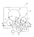
図1に示すように、内容物充填システム10は、入口側搬送装置(入口ホイル)11と、充填装置(フィラー)20と、出口側搬送装置(出口ホイル)13と、キャップ装着装置(キャッパー、巻締及び打栓機)16と、移送装置18とを備えている。これら入口側搬送装置11、充填装置20、出口側搬送装置13、キャップ装着装置16、および移送装置18は、ボトル30の搬送方向に沿って、上流側から下流側に向けてこの順に配設されている。
As shown in FIG. 1, the
入口側搬送装置11は、外部から内容物充填システム10へ空のボトル30を順次受け入れ、受け入れたボトル30を充填装置20へ向けて搬送するものである。入口側搬送装置11は、回転する搬送ホイール12を有しており、この搬送ホイール12によって複数のボトル30が回転(公転)しながら充填装置20へ連続的に搬送される。
The inlet-
充填装置20は、ボトル30の口部31からボトル本体32内へ内容物Lを充填するものである。この充填装置20において、空の状態のボトル30に対して内容物Lが充填される。
The
充填装置20は、回転する搬送ホイール21を有しており、この搬送ホイール21によって複数のボトル30が回転(公転)されながら、ボトル30内部へ内容物Lが充填される。また搬送ホイール21の外周に沿って、複数の充填ノズル22(図2参照)が配置されている。各充填ノズル22には、それぞれ1本のボトル30が装着され、充填ノズル22からボトル30の内部に内容物Lが注入される。
The
図2に示すように、充填ノズル22は公知であるが、本体部23と、本体部23にそれぞれ接続された内容物供給ライン24およびガス供給ライン25とを有している。このうち内容物供給ライン24は、その上端が内容物Lを充填したヘッドタンク27(又はフィラーボール)に接続されるとともに、下端においてボトル30の内部に連通している。そしてヘッドタンク27から供給された内容物Lは、内容物供給ライン24を通過して、ボトル30の内部に注入されるようになっている。また、ガス供給ライン25は、その上端がヘッドタンク27に接続されるとともに、下端においてボトル30の内部に連通している。ヘッドタンク27から供給された炭酸ガス等のカウンタープレッシャー用のガスは、ガス供給ライン25を通過して、ボトル30の内部に充填されるようになっている。ガス供給ライン25の途中には、スニフトライン26が接続されており、スニフトライン26を介してボトル30の内部のガスを排出可能となっている。
As shown in FIG. 2, the
内容物Lが炭酸飲料からなる場合、充填ノズル22での充填時における内容物Lの温度は例えば1℃〜10℃であり、好ましくは5℃〜10℃である。このように内容物Lの温度を例えば1℃〜10℃とする理由は、液温が10℃を上回ると炭酸ガスが内容物Lから抜けやすくなってしまうためである。
When the content L consists of carbonated drinks, the temperature of the content L at the time of filling with the
内容物Lは、充填後に発泡が生じやすい液体であり、例えば炭酸ガスを含む各種飲料、例えば、サイダー、コーラ等の炭酸飲料、ビール等のアルコール飲料等が挙げられる。内容物Lとしては、炭酸を含まない飲料であっても良い。炭酸を含まない飲料としては、お茶、機能性飲料、ジュース、コーヒー、牛乳、乳入り飲料などミネラルウォーター以外のすべての飲料が含まれる。あるいは、内容物Lは、食器用洗剤、洗濯用洗剤、液体石鹸等、界面活性剤を含む非飲料用液体であっても良い。 The content L is a liquid that is easily foamed after filling, and examples thereof include various beverages containing carbon dioxide, such as carbonated beverages such as cider and cola, and alcoholic beverages such as beer. The content L may be a beverage that does not contain carbonic acid. Non-carbonated beverages include all beverages other than mineral water, such as tea, functional beverages, juices, coffee, milk and beverages with milk. Alternatively, the content L may be a non-beverage liquid containing a surfactant, such as a dishwashing detergent, a laundry detergent, or a liquid soap.
再度図1を参照すると、充填装置20の下流側には、出口側搬送装置13が設けられている。出口側搬送装置13は、充填装置20で内容物Lが充填された後閉栓される前のボトル30を、キャップ装着装置16へ向けて搬送するものである。出口側搬送装置13は、回転する搬送ホイール14を有しており、この搬送ホイール14によって複数のボトル30が回転(公転)しながらキャップ装着装置16へ連続的に搬送される。
Referring to FIG. 1 again, an outlet-
出口側搬送装置13には、ノズルユニット15が設けられている。このノズルユニット15は、図示しない口部洗浄ノズル及び/又は不活性ガス(窒素)置換用ノズルを有している。口部洗浄ノズルは、連続的に搬送されるボトル30の口部31を洗浄液又は洗浄ガスによって洗浄するためのノズルである。また、不活性ガス置換用ノズルは、連続的に搬送されるボトル30のヘッドスペース中のガスを不活性ガスによって置換するためのノズルである。
The outlet
出口側搬送装置13によって搬送される間、ボトル30に充填された内容物L中に泡が生じる場合がある。この泡の量が少量であると、泡はボトル30の内部に留まるが、泡の量が多量になった場合、口部31から外部に放出されてしまう場合がある。このため、本実施の形態においては、出口側搬送装置13に、ボトル30の口部31から放出された泡の有無を自動で検出する泡検出装置40が設けられている。
While being conveyed by the outlet
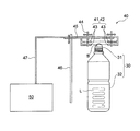
本実施の形態において、泡検出装置40は、ノズルユニット15よりも上流側に位置する第1泡検出装置41と、第1泡検出装置41及びノズルユニット15よりも下流側に位置する第2泡検出装置42とを含んでいる。このうち第1泡検出装置41は、ボトル30に内容物Lが充填された直後に口部31から放出される泡を検出するためのものである。一方、第2泡検出装置42は、ボトル30に内容物Lが充填された後一定時間を経過してから口部31から放出される泡を検出するためのものである。
In the present embodiment, the
内容物Lから発生する泡は、内容物Lの種類や充填速度等の各種要因により、その成長速度が異なる。このため、上流側の第1泡検出装置41と下流側の第2泡検出装置42との両方を設けることにより、ボトル30に内容物Lが充填された直後(内容物Lの充填から第1泡検出装置41に到達する間)に口部31から放出される、成長速度が速い泡を第1泡検出装置41で検出し、ボトル30に内容物Lが充填された後一定時間を経過してから(第1泡検出装置41を通過してから第2泡検出装置42に到達するまでの間に)口部31から放出される、成長速度が遅い泡を第2泡検出装置42で検出することができる。これにより、成長速度が異なる様々な泡を検出することが可能となる。なお、第1泡検出装置41及び第2泡検出装置42とは異なる位置に、更に別の泡検出装置を設けても良い。
Bubbles generated from the contents L have different growth rates depending on various factors such as the type of the contents L and the filling speed. For this reason, by providing both the first
泡検出装置40の第1泡検出装置41及び第2泡検出装置42には、それぞれ判定部50が接続されている。判定部50は、第1泡検出装置41及び/又は第2泡検出装置42によって泡が放出されたボトル30が検出された際、当該泡が放出されたボトル30を特定する機能を有する。泡が放出されたボトル30を特定する方法は問わないが、例えば、充填装置20の搬送ホイール21のうち各ボトル30を収容する箇所にそれぞれ位置番号を付与し、各ボトル30が第1泡検出装置41又は第2泡検出装置42を通過した際、通過したボトル30に対応する位置番号を判定部50が認識し、これにより泡が放出されたボトル30を特定しても良い。また、充填装置20の出入口にボトル30を検出するセンサーを設け、これによりボトル30の位置を特定しても良い。
A
図3を参照すると、泡検出装置40の第1泡検出装置41及び第2泡検出装置42は、それぞれ一対の光電センサー(検出部)43、43を有している。一対の光電センサー43、43は、ボトル30の口部31よりも上方であって、口部31から放出された泡Bの両側(ボトル30の進行方向両側)に配置されている。一対の光電センサー43、43は、それぞれブラケット44に取り付けられており、各ブラケット44は、それぞれ水平取付部材45に対して水平移動可能に取り付けられている。また、水平取付部材45は、固定部材46に対して垂直方向に移動可能に取り付けられている。これにより、対向する一対の光電センサー43、43同士の間隔や、光電センサー43の口部31に対する高さ位置を調整可能となっている。なお、光電センサー43としては、従来公知のものを用いることができる。本実施の形態において、第1泡検出装置41及び第2泡検出装置42は互いに同一の構成からなっているが、これに限られるものではなく、第1泡検出装置41と第2泡検出装置42とが互いに異なる構成からなっていても良い。
Referring to FIG. 3, the first
光電センサー43は、通信ケーブル47を介して判定部50に接続されている。判定部50は、コンピュータ等の演算装置であってもよい。また、光電センサー43と判定部50との間には、図示しないアンプやシーケンサ等が介在されていても良い。
The
再度図1を参照すると、判定部50は、調整部51に接続されている。この調整部51は、判定部50からの情報に基づき、充填装置20による充填条件を調整するものである。充填条件としては、例えば、充填装置20におけるボトル30の移動速度(充填時間)、内容物Lの充填量、充填温度、充填時の圧力(カウンター圧力)、保持時間、スニフト時間、大投充填及び小投充填の調整(時間、量)等が挙げられる。このように、判定部50からの情報をフィードバックし、調整部51が充填装置20による充填条件を調整することにより、口部31から泡が放出されにくい充填条件で内容物Lを充填することができる。これにより、口部31から泡が放出されるボトル30を減らし、製品の歩留まりを向上させることができる。また、内容物Lの液種が異なると泡の発生状況も異なる。そこで従来は、一つ一つの充填要素を振って、1つの液種にあった最適な充填プロセスを目視検査で作成していた。しかし、この内容物充填システム10により高速で搬送されるボトル30に対して、どの要素が最も泡発生メカニズムに寄与しているか統計的に、自動で把握することが可能である。また、製造中得られた結果をリアルタイムに充填プロセスにフィードバックすることもできる。これにより、日々液種が異なっても充填開始とともに最適化作業が行われ、自動で最適な充填プロセスを導き出すことができる。
Referring to FIG. 1 again, the
なお、判定部50は、調整部51と別体に構成されているが、これに限らず、判定部50と調整部51とが1つの装置内で一体化されていても良い。また、内容物充填システム10の全体を制御する制御部が、判定部50と調整部51とを兼ねていても良い。
In addition, although the
出口側搬送装置13及び泡検出装置40の下流側には、ボトル30を排出する排出部60が設けられている。排出部60は、判定部50に接続されている。この排出部60は、判定部50で特定された、泡が放出されたボトル30を選択的に排出するものである。例えば、充填装置20の搬送ホイール21のうち各ボトル30を収容する箇所に位置番号が付与されている場合、判定部50は、泡が放出されたボトル30に対応する位置番号を特定し、これを排出部60に送信する。排出部60は、対応する位置番号に収容されたボトル30が到着したとき、このボトル30を選択して排出する。一方、泡検出装置40によって泡が検出されなかったボトル30は、排出部60へ送られることなく、キャップ装着装置16に送られる。
A
キャップ装着装置16は、出口側搬送装置13及び泡検出装置40の下流側に設けられている。このキャップ装着装置16は、ボトル30の口部31に図示しないキャップを装着することにより、ボトル30を閉栓するものである。キャップ装着装置16は、回転する搬送ホイール17を有しており、この搬送ホイール17によって複数のボトル30が回転(公転)しながらその口部31にキャップが装着され、移送装置18へ連続的に搬送される。このように、ボトル30の口部31にキャップを装着することにより、内容物入りボトル35が得られる。
The
移送装置18は、キャップ装着装置16でキャップを装着された内容物入りボトル35を、キャップ装着装置16から内容物充填システム10の外部に向けて搬出するものである。キャップ装着装置16は、回転する搬送ホイール19を有している。移送装置18には出口コンベア38が接続されている。この搬送ホイール19によって、複数の内容物入りボトル35が回転(公転)しながら出口コンベア38に渡され、内容物充填システム10の外部へ連続的に搬出される。
The
なお、内容物充填システム10は、チャンバ70を有している。チャンバ70内に、上述した入口側搬送装置11、充填装置20、出口側搬送装置13、キャップ装着装置16、および移送装置18が収容されている。
The
このような内容物充填システム10は、例えば無菌充填システムからなっていても良い。この場合、チャンバ70の内部が無菌状態に保持されている。あるいは、内容物Lがコーラ等の殺菌不要な飲料からなる場合、チャンバ70の内部が、異物等が除去されたクリーンルームからなっていても良い。
Such a
(内容物充填方法)
次に、本実施の形態による内容物充填方法について説明する。本実施の形態による内容物充填方法は、上述した内容物充填システム10(図1)を用いて行われるものである。
(Content filling method)
Next, the content filling method according to the present embodiment will be described. The content filling method according to the present embodiment is performed using the above-described content filling system 10 (FIG. 1).
まず複数の空のボトル30が、内容物充填システム10の外部から入口側搬送装置11へ順次供給される。このボトル30は、入口側搬送装置11の搬送ホイール12によって回転搬送され、充填装置20へ送られる。
First, a plurality of
続いて、充填装置20において、ボトル30は搬送ホイール21に保持され、搬送ホイール21によって回転(公転)されながら、口部31からボトル本体32内へ内容物Lが充填される(充填工程)。
Subsequently, in the filling
次に、充填装置20において、充填ノズル22がボトル30の口部31に密着し、ガス供給ライン25とボトル30とが互いに連通する。次に、ガス供給ライン25からボトル30の内部にカウンタープレッシャー用のガスが供給される。これにより、ボトル30の内圧が大気圧よりも高められ、ボトル30の内圧がヘッドタンク27(図2参照)の内圧と同一の圧力となる。
Next, in the filling
次に、内容物供給ライン24からボトル30の内部に内容物Lが充填される。この場合、内容物Lはヘッドタンク27(図2参照)から内容物供給ライン24を通過して、ボトル30の内部に注入される。この間、大投充填と小投充填とを切り換えるようにしても良い。
Next, the contents L are filled into the
続いて、内容物供給ライン24からの内容物Lの供給を停止する。続いて、スニフトライン26を開放し、スニフトライン26からボトル30内部のガスを排出する。
Subsequently, the supply of the content L from the
その後、ボトル30内部の圧力が大気圧と等しくなり、ボトル30への内容物Lの充填が完了する。このときボトル30内の内容物L中に泡が生じ、この泡が口部31から外部に放出される場合がある。
Thereafter, the pressure inside the
続いて、内容物Lが充填されたボトル30は、充填装置20から出口側搬送装置13(図1参照)に送られる。このときボトル30は、出口側搬送装置13の搬送ホイール14によって回転搬送され、泡検出装置40の第1泡検出装置41へと送られる。
Subsequently, the
続いて、第1泡検出装置41において、ボトル30の口部31から放出された泡(とりわけ充填直後に放出される泡)の有無が自動で検出される(第1泡検出工程)。具体的には、口部31から放出された泡が第1泡検出装置41の一対の光電センサー43、43(図3参照)の感知領域を通過した場合、光電センサー43が泡を検出する。この場合、光電センサー43から判定部50(図1参照)へ信号が送られる。
Subsequently, in the first
続いて判定部50は、光電センサー43からの信号に基づき、泡が放出されたボトル30を特定する(判定工程)。例えば、充填装置20の搬送ホイール21のうち各ボトル30を収容する箇所に位置番号が付与されている場合、判定部50は、泡が放出されたボトル30に対応する位置番号を特定する。続いて、判定部50は、泡が放出されたボトル30に対応する位置番号を排出部60に送信する。
Subsequently, the
なお、第1泡検出装置41の光電センサー43が泡を検出しなかった場合、光電センサー43から判定部50へは信号が送られない。
Note that when the
第1泡検出装置41を通過したボトル30は、口部31から泡が放出されているか否かに関わらず、ノズルユニット15内を通過し、この間口部31が洗浄され、及び/又は、ヘッドスペース中のガスが不活性ガスによって置換される。ノズルユニット15内の洗浄装置を使用した場合、水が搬送ホイール14の廻りに飛散し、光電センサー43を遮光する或いはノイズになる場合がある。その際は、光電センサー43の受光部にエアをあて水を除去すると良い。チャンバ70が無菌チャンバであり、この無菌チャンバ内で使用する場合は、洗浄水とエアは除菌されたものを使う必要がある。
The
ノズルユニット15内を通過したボトル30は、引き続き搬送ホイール14によって回転搬送され、第2泡検出装置42へと送られる。次に、第2泡検出装置42において、ボトル30の口部31から放出された泡(とりわけ充填後一定時間を経過してから放出される泡)の有無が自動で検出される(第2泡検出工程)。
The
第2泡検出装置42で口部31から放出された泡が検出された場合、第2泡検出装置42から判定部50へ信号が送られ、判定部50は、泡が放出されたボトル30を特定する(判定工程)。次に、判定部50は、泡が放出されたボトル30に対応する位置番号を排出部60に送信する。
When the foam released from the
なお、第2泡検出工程における検出方法は、第1泡検出工程の場合と略同様である。また本実施の形態において、第1泡検出工程と第2泡検出工程とにより、泡検出工程が構成される。 In addition, the detection method in a 2nd bubble detection process is as substantially the same as the case of a 1st bubble detection process. Moreover, in this Embodiment, a bubble detection process is comprised by the 1st bubble detection process and the 2nd bubble detection process.
次いで、第2泡検出装置42を通過したボトル30は、排出部60(図1参照)の近傍に到達する。このとき、排出部60は、判定部50からの信号に基づき、泡が放出されたボトル30を選択し、これを出口側搬送装置13から排出する。なお、排出部60は、第1泡検出装置41および第2泡検出装置42のうち、いずれか一方で泡が検出されたボトル30を選択して排出しても良く、両方とも泡が検出されたボトル30を選択して排出しても良い。
Next, the
一方、泡が検出されなかったボトル30は、出口側搬送装置13からキャップ装着装置16(図1参照)に搬送される。このキャップ装着装置16において、ボトル30の口部31に図示しないキャップを装着することにより、内容物入りボトル35が得られる(キャップ装着工程)。
On the other hand, the
その後、内容物入りボトル35は、キャップ装着装置16から移送装置18へ搬送され、移送装置18から内容物充填システム10の外部へ向けて搬出される。
Thereafter, the
なお、本実施の形態において、ボトル30の生産(搬送)速度は、100bpm〜1500bpmとすることが好ましい。ここでbpm(bottle per minute)とは、1分間当たりのボトル30の搬送速度をいう。
In the present embodiment, the production (conveyance) speed of the
以上のように本実施の形態によれば、泡検出装置40が、ボトル30に充填された内容物L中に生じ、ボトル30の口部31から放出された泡の有無を自動で検出する。また判定部50は、泡が放出されたボトル30を特定する。これにより、作業者の人手に頼ることなく、ボトル30の口部31から放出された泡の有無を自動で検出することが可能となる。この結果、ボトル30内の内容物Lの量が所定量よりも不足してしまったり、口部31の外周に内容物Lが付着してしまったりする不具合を防止することができる。
As described above, according to the present embodiment, the
また従来、作業者が泡の有無を目視で検査し、泡が噴き出しているおそれのあるボトル30をまとめて廃棄する場合があったが、本実施の形態によれば、口部31から泡の生じたボトル30のみを選択して廃棄することができるため、廃棄されるボトル30の数を減らし、製品の歩留まりを向上させることができる。
In addition, conventionally, there is a case where the operator visually inspects the presence or absence of bubbles and discards the
また本実施の形態によれば、泡検出装置40は、ボトル30に内容物Lが充填された直後に口部31から放出される泡を検出する第1泡検出装置41と、ボトル30に内容物Lが充填された後一定時間を経過してから口部31から放出される泡を検出する第2泡検出装置42とを含んでいる。これにより、泡検出装置40によって、成長速度が異なる様々な泡を検出することができ、口部31から泡が放出されたボトル30を確実に取り除くことができる。
Moreover, according to this Embodiment, the
また本実施の形態によれば、泡が放出されたボトル30を排出する排出部60が設けられているので、泡が放出されたボトル30を自動で確実に取り除くことができる。
Moreover, according to this Embodiment, since the
また本実施の形態によれば、排出部60は、キャップ装着装置16でボトル30の口部31にキャップを装着する前に、泡が放出されたボトル30を排出する。これにより、廃棄すべきボトル30にキャップを装着してしまうおそれがなく、キャップが無駄になることが防止される。
Further, according to the present embodiment, the
また本実施の形態によれば、判定部50からの情報に基づき、充填装置20による充填条件を調整する調整部51が設けられている。この調整部51が判定部50からの情報をフィードバックすることにより、充填装置20による充填条件と、泡の発生との関係を把握することができる。また、判定部50からの情報に基づいて、口部31から泡が放出されにくくなるように、充填装置20による充填条件を調整することができる。
Moreover, according to this Embodiment, the
(変形例)
次に、図4乃至図6により、本実施の形態の各変形例について説明する。図4乃至図6において、図1乃至図3に示す実施の形態と同一部分には同一の符号を付して、詳細な説明は省略する。
(Modification)
Next, each modification of the present embodiment will be described with reference to FIGS. 4 to 6, the same parts as those of the embodiment shown in FIGS. 1 to 3 are denoted by the same reference numerals, and detailed description thereof is omitted.
上述した実施の形態において、排出部60がキャップ装着装置16よりも上流側に設けられている場合を例にとって説明したが、これに限られるものではない。例えば図4に示すように、排出部60は、キャップ装着装置16の下流側に設けられていても良い。これにより、排出部60を出口側搬送装置13周辺の空間に配置する必要がないので、出口側搬送装置13周辺のスペースを有効に利用することができる。この場合、キャップ装着装置16は、泡が放出されたボトル30の口部31にはキャップ(図示せず)を装着することなく、当該ボトル30を排出部60に搬送することが好ましい。これにより、廃棄すべきボトル30にキャップを装着しないので、キャップが無駄になってしまうことを防止することができる。
In the above-described embodiment, the case where the
あるいは、図5に示すように、排出部60は、出口コンベア38に設けられていても良い。泡が放出されたボトル30は、規定のピッチで搬送されるため、出口コンベア38にある排出部60で出口コンベア38から排斥される。この場合、キャップは巻締めた状態であっても良く、キャップが装着されていない状態であっても良い。
Alternatively, as shown in FIG. 5, the
また、図6に示すように、泡検出装置40の第1泡検出装置41及び/又は第2泡検出装置42は、上下方向に複数(例えば2つ)の光電センサー(検出部)43、43を有していても良い。この場合、口部31から放出された高さの異なる泡Bを検出することが可能となる。例えば、下方に位置する光電センサー43が相対的に高さの低い泡Bを検出し、上方に位置する光電センサー43が相対的に高さの高い泡Bを検出することができる。
As shown in FIG. 6, the first
次に、本実施の形態における具体的実施例について説明する。 Next, specific examples in the present embodiment will be described.
図1に示す内容物充填システム10を用い、口部31から泡が放出されたボトル30を用意し、これを一対の光電センサー43、43間を通過させて実際に泡が検出できるか否かを確認した。なお、ボトル30の搬送速度は720bpmとした。
Using the
内容物Lとしては、食器用洗剤、コーラ、メロンクリームソーダの3種類を準備し、それぞれについて5回ずつテストを実施した。 As the contents L, three types of dishwashing detergent, cola, and melon cream soda were prepared, and the test was carried out five times for each.
この結果、内容物Lが食器用洗剤、コーラ、メロンクリームソーダのいずれであった場合においても、口部31から放出された泡を検出することができた(表1参照)。
As a result, even when the contents L were any of dish detergent, cola, and melon cream soda, foam released from the

10 内容物充填システム
11 入口側搬送装置
13 出口側搬送装置
15 ノズルユニット
16 キャップ装着装置
18 移送装置
20 充填装置
30 ボトル
31 口部
32 ボトル本体
35 内容物入りボトル
40 泡検出装置
41 第1泡検出装置
42 第2泡検出装置
50 判定部
51 調整部
60 排出部
DESCRIPTION OF
Claims (10)
前記充填装置の下流側に設けられ、前記容器に充填された前記内容物中に生じ、前記容器の前記口部から放出された泡の有無を自動で検出する泡検出装置と、
前記泡検出装置に接続され、泡が放出された容器を特定する判定部とを備えたことを特徴とする内容物充填システム。 A filling device for filling the contents of a container having a mouth portion and a container body;
A foam detection device that is provided on the downstream side of the filling device and that automatically detects the presence or absence of bubbles generated in the contents filled in the container and discharged from the mouth of the container;
A content filling system comprising: a determination unit that is connected to the bubble detection device and identifies a container from which bubbles are released.
前記容器に前記内容物が充填された直後に前記口部から放出される泡を検出する第1泡検出装置と、
前記第1泡検出装置の下流側に設けられ、前記容器に前記内容物が充填された後一定時間を経過してから前記口部から放出される泡を検出する第2泡検出装置とを含むことを特徴とする請求項1記載の内容物充填システム。 The bubble detection device
A first bubble detection device that detects bubbles released from the mouth immediately after the container is filled with the contents;
A second bubble detection device that is provided downstream of the first bubble detection device and detects bubbles released from the mouth after a predetermined time has elapsed after the container is filled with the contents. The content filling system according to claim 1.
前記排出部は、前記キャップ装着装置で前記容器の前記口部に前記キャップを装着する前に、前記泡が放出された容器を排出することを特徴とする請求項3記載の内容物充填システム。 A cap mounting device that is provided on the downstream side of the foam detection device and mounts a cap on the mouth of the container;
4. The content filling system according to claim 3, wherein the discharging unit discharges the container from which the bubbles are released before mounting the cap on the mouth of the container by the cap mounting device.
前記排出部は、前記キャップ装着装置の下流側に設けられていることを特徴とする請求項3記載の内容物充填システム。 A cap mounting device that is provided on the downstream side of the foam detection device and mounts a cap on the mouth of the container;
4. The content filling system according to claim 3, wherein the discharge unit is provided on a downstream side of the cap mounting device.
前記充填工程の後、前記容器に充填された前記内容物中に生じ、前記容器の前記口部から放出された泡の有無を自動で検出する泡検出工程と、
前記泡検出工程の後、前記泡が放出された容器を特定する判定工程とを備えたことを特徴とする内容物充填方法。 A filling step of filling the contents into a container having a mouth and a container body;
After the filling step, a bubble detection step for automatically detecting the presence or absence of bubbles generated in the contents filled in the container and released from the mouth of the container;
After the said foam detection process, the determination process which specifies the container in which the said foam was discharge | released was provided, The content filling method characterized by the above-mentioned.
前記容器に前記内容物が充填された直後に前記口部から放出される泡を検出する第1泡検出工程と、
前記第1泡検出工程の後、前記容器に前記内容物が充填された後一定時間を経過してから前記口部から放出される泡を検出する第2泡検出工程とを含むことを特徴とする請求項9記載の内容物充填方法。 The bubble detection step includes
A first bubble detection step of detecting bubbles released from the mouth immediately after the container is filled with the contents;
A second bubble detecting step of detecting bubbles released from the mouth after a predetermined time has elapsed after the container has been filled with the contents after the first bubble detecting step. The content filling method according to claim 9.
Priority Applications (5)
| Application Number | Priority Date | Filing Date | Title |
|---|---|---|---|
| JP2015249890A JP6222213B2 (en) | 2015-12-22 | 2015-12-22 | Contents filling system and contents filling method |
| CN201680073793.7A CN108367904B (en) | 2015-12-22 | 2016-12-21 | Content filling system and content filling method |
| PCT/JP2016/088156 WO2017110899A1 (en) | 2015-12-22 | 2016-12-21 | Content filling system and content filling method |
| EP16878786.9A EP3395751B1 (en) | 2015-12-22 | 2016-12-21 | Content filling system and content filling method |
| US16/015,537 US11247887B2 (en) | 2015-12-22 | 2018-06-22 | Content filling system and content filling method |
Applications Claiming Priority (1)
| Application Number | Priority Date | Filing Date | Title |
|---|---|---|---|
| JP2015249890A JP6222213B2 (en) | 2015-12-22 | 2015-12-22 | Contents filling system and contents filling method |
Related Child Applications (2)
| Application Number | Title | Priority Date | Filing Date |
|---|---|---|---|
| JP2017195285A Division JP6515972B2 (en) | 2017-10-05 | 2017-10-05 | Content filling system and content filling method |
| JP2017195290A Division JP6620997B2 (en) | 2017-10-05 | 2017-10-05 | Contents filling system and contents filling method |
Publications (2)
| Publication Number | Publication Date |
|---|---|
| JP2017114501A true JP2017114501A (en) | 2017-06-29 |
| JP6222213B2 JP6222213B2 (en) | 2017-11-01 |
Family
ID=59231471
Family Applications (1)
| Application Number | Title | Priority Date | Filing Date |
|---|---|---|---|
| JP2015249890A Active JP6222213B2 (en) | 2015-12-22 | 2015-12-22 | Contents filling system and contents filling method |
Country Status (1)
| Country | Link |
|---|---|
| JP (1) | JP6222213B2 (en) |
Citations (9)
| Publication number | Priority date | Publication date | Assignee | Title |
|---|---|---|---|---|
| JPS6045189A (en) * | 1983-08-11 | 1985-03-11 | マンズワイン株式会社 | Method and device for correcting cork stopper |
| JPH01199892A (en) * | 1988-11-29 | 1989-08-11 | Manzuwain Kk | Method and apparatus for correcting cork |
| JPH0343397A (en) * | 1989-06-30 | 1991-02-25 | Mitsubishi Heavy Ind Ltd | Bottling and capping apparatus |
| JPH07125705A (en) * | 1993-02-27 | 1995-05-16 | Apv Orthmann & Herbst Gmbh | Drink charger for transparent container |
| JPH09218077A (en) * | 1996-02-14 | 1997-08-19 | Hitachi Eng Co Ltd | Method and device for measuring liquid level |
| JP2002053198A (en) * | 2000-08-10 | 2002-02-19 | Asahi Breweries Ltd | Method and apparatus for manufacturing bottled beer and method for manufacturing enclosure |
| WO2014077319A1 (en) * | 2012-11-16 | 2014-05-22 | 大日本印刷株式会社 | Method for cleaning beverage bottling apparatus |
| JP2014125222A (en) * | 2012-12-26 | 2014-07-07 | Kirin Brewery Co Ltd | Inspection apparatus |
| JP2014231356A (en) * | 2013-05-02 | 2014-12-11 | 東洋製罐株式会社 | Aseptic filling method of beverage and system |
-
2015
- 2015-12-22 JP JP2015249890A patent/JP6222213B2/en active Active
Patent Citations (9)
| Publication number | Priority date | Publication date | Assignee | Title |
|---|---|---|---|---|
| JPS6045189A (en) * | 1983-08-11 | 1985-03-11 | マンズワイン株式会社 | Method and device for correcting cork stopper |
| JPH01199892A (en) * | 1988-11-29 | 1989-08-11 | Manzuwain Kk | Method and apparatus for correcting cork |
| JPH0343397A (en) * | 1989-06-30 | 1991-02-25 | Mitsubishi Heavy Ind Ltd | Bottling and capping apparatus |
| JPH07125705A (en) * | 1993-02-27 | 1995-05-16 | Apv Orthmann & Herbst Gmbh | Drink charger for transparent container |
| JPH09218077A (en) * | 1996-02-14 | 1997-08-19 | Hitachi Eng Co Ltd | Method and device for measuring liquid level |
| JP2002053198A (en) * | 2000-08-10 | 2002-02-19 | Asahi Breweries Ltd | Method and apparatus for manufacturing bottled beer and method for manufacturing enclosure |
| WO2014077319A1 (en) * | 2012-11-16 | 2014-05-22 | 大日本印刷株式会社 | Method for cleaning beverage bottling apparatus |
| JP2014125222A (en) * | 2012-12-26 | 2014-07-07 | Kirin Brewery Co Ltd | Inspection apparatus |
| JP2014231356A (en) * | 2013-05-02 | 2014-12-11 | 東洋製罐株式会社 | Aseptic filling method of beverage and system |
Also Published As
| Publication number | Publication date |
|---|---|
| JP6222213B2 (en) | 2017-11-01 |
Similar Documents
| Publication | Publication Date | Title |
|---|---|---|
| EP3578503B1 (en) | Beverage aseptic filling system | |
| JP6075535B2 (en) | Filling and sealing method and apparatus | |
| CN105752418A (en) | Drink filling method and drink filling device | |
| US11655133B2 (en) | Cap sterilizer, content filling system, cap sterilization method, and content filling method | |
| JP6449357B2 (en) | Beverage aseptic filling system | |
| CN108394083A (en) | Container transport and cooling device and its operating method and machines for treating containers with this container transport and cooling device | |
| JP7283507B2 (en) | Content filling system and content filling method | |
| WO2017110899A1 (en) | Content filling system and content filling method | |
| JP6620997B2 (en) | Contents filling system and contents filling method | |
| JP6222213B2 (en) | Contents filling system and contents filling method | |
| JP6515972B2 (en) | Content filling system and content filling method | |
| JP6004161B2 (en) | Container processing equipment | |
| JP5833840B2 (en) | Bottle conveyor | |
| JP4098570B2 (en) | Square container alignment device | |
| JP6394644B2 (en) | Cap sterilizer and contents filling system | |
| CN103449342A (en) | Container closing apparatus | |
| JP2020158147A (en) | Content filling system | |
| EP3026007A1 (en) | A filling head for filling containers | |
| JP6627918B2 (en) | Carbonated beverage aseptic filling system | |
| JP2013189235A (en) | Preform sterilization method and device | |
| JP2018184221A (en) | Cap sterilization device and content filling system | |
| Faltermeier | Bottle Manufacture and Filling Equipment | |
| CN107776939A (en) | A kind of preposition detection straw packing machine of sterilization formula |
Legal Events
| Date | Code | Title | Description |
|---|---|---|---|
| A521 | Request for written amendment filed |
Free format text: JAPANESE INTERMEDIATE CODE: A523 Effective date: 20170518 |
|
| TRDD | Decision of grant or rejection written | ||
| A01 | Written decision to grant a patent or to grant a registration (utility model) |
Free format text: JAPANESE INTERMEDIATE CODE: A01 Effective date: 20170905 |
|
| A61 | First payment of annual fees (during grant procedure) |
Free format text: JAPANESE INTERMEDIATE CODE: A61 Effective date: 20170918 |
|
| R150 | Certificate of patent or registration of utility model |
Ref document number: 6222213 Country of ref document: JP Free format text: JAPANESE INTERMEDIATE CODE: R150 |