JP2017108687A - Work vehicle - Google Patents
Work vehicle Download PDFInfo
- Publication number
- JP2017108687A JP2017108687A JP2015246139A JP2015246139A JP2017108687A JP 2017108687 A JP2017108687 A JP 2017108687A JP 2015246139 A JP2015246139 A JP 2015246139A JP 2015246139 A JP2015246139 A JP 2015246139A JP 2017108687 A JP2017108687 A JP 2017108687A
- Authority
- JP
- Japan
- Prior art keywords
- work
- vehicle body
- traveling
- vehicle
- detection sensor
- Prior art date
- Legal status (The legal status is an assumption and is not a legal conclusion. Google has not performed a legal analysis and makes no representation as to the accuracy of the status listed.)
- Pending
Links
Images


Abstract
Description
本発明は、作業機を機体後部に装着した、トラクタなどの作業車両に関する。 The present invention relates to a work vehicle such as a tractor in which a work machine is mounted on a rear part of a machine body.
路上走行時に誤操作などで作業機が下降すると、路面と作業機が接触し、双方が損傷するおそれがあり、これを避けるために作業機を上昇させたままにしていなければ、エンジン回転が抑制されて、路上走行が出来ないような設定になっている技術(特開平10−164907号公報)がある。 If the work implement is lowered due to an erroneous operation while traveling on the road, the road surface and the work implement may come into contact with each other, possibly damaging them. If the work implement is not lifted to avoid this, engine rotation is suppressed. In addition, there is a technique (Japanese Patent Laid-Open No. 10-164907) that is set so as not to run on the road.
しかし、上記特許文献1記載の構成では、例えば小型の作業車両の場合には作業機を上昇させると、機体の後部に配置している反射鏡などの反射材が隠れてしまうことがあり、路上走行時に反射材が後続車両から見えず、安全性の観点から路上走行には適さないという問題があった。 However, in the configuration described in Patent Document 1, for example, in the case of a small work vehicle, when the work implement is raised, a reflector such as a reflector disposed at the rear of the fuselage may be hidden, and the road There is a problem that the reflective material is not visible from the following vehicle during traveling, and is not suitable for traveling on the road from the viewpoint of safety.
そこで本発明の課題は、走行車体に反射材を備えた作業車両において、作業機が上昇した状態の時でも、安全性が確保され、路上走行にも適した作業車両を提供することである。 SUMMARY OF THE INVENTION An object of the present invention is to provide a work vehicle in which safety is ensured even in a state in which a work machine is raised in a work vehicle having a reflective body on a traveling vehicle body, and is suitable for traveling on the road.
本発明の上記課題は次の解決手段により解決される。
請求項1記載の発明は、走行装置(2,3)を備えた走行車体(1)と、走行車体(1)の後部に昇降自在に設けた作業機(22)と、走行車体(1)と作業機(22)との間に設けた反射材(36,70b)と、反射材(36,70b)の近傍に設けられ、反射材(36,70b)から所定距離以内の後方にある、反射材(36,70b)の遮蔽物の有無を検出する遮蔽物検出センサ(60)と、遮蔽物検出センサ(60)により遮蔽物が有ることが検出されると、反射材(36,70b)が遮蔽状態であることを報知する走行車体(1)上の報知手段(65,67)を作動させる制御装置(100)とを設けた作業車両である。
The above-described problems of the present invention are solved by the following solution means.
The invention according to claim 1 is a traveling vehicle body (1) provided with a traveling device (2, 3), a work machine (22) provided at a rear portion of the traveling vehicle body (1), and a traveling vehicle body (1). And the reflector (36, 70b) provided between the reflector and the work machine (22), provided in the vicinity of the reflector (36, 70b), and within a predetermined distance from the reflector (36, 70b). A shielding object detection sensor (60) for detecting the presence or absence of a shielding material on the reflecting material (36, 70b), and when the shielding object detection sensor (60) detects that there is a shielding object, the reflecting material (36, 70b). Is a work vehicle provided with a control device (100) for operating notification means (65, 67) on the traveling vehicle body (1) for notifying that the vehicle is in a shielded state.
請求項2記載の発明は、前記反射材(70b)が、農業用の作業車両の低速車マーク(70)である請求項1記載の作業車両である。 A second aspect of the present invention is the work vehicle according to the first aspect, wherein the reflective member (70b) is a low-speed vehicle mark (70) of an agricultural work vehicle.
作業車両の路上走行時には反射材(36,70b)が後続車両に視認できる状態である必要があるが、作業機等によって反射材(36,70b)が隠れていても運転者は気がつきにくい。従って、そのままの状態で走行を継続してしまう場合がある。 When the work vehicle travels on the road, the reflective material (36, 70b) needs to be visible to the following vehicle. However, even if the reflective material (36, 70b) is hidden by a work machine or the like, it is difficult for the driver to notice. Therefore, there are cases where the vehicle continues to run in the same state.
しかし、請求項1記載の発明によれば、遮蔽物検出センサ(60)によって反射材(36,70b)が遮蔽状態であることが検知されると報知されるため、運転者は直ぐに遮蔽状態であることに気がつく。従って、遮蔽状態のままで走行を継続してしまうことを防止でき、安全性が確保される。 However, according to the first aspect of the invention, since it is notified that the reflecting material (36, 70b) is in the shielding state by the shielding object detection sensor (60), the driver is immediately in the shielding state. I notice that there is. Therefore, it can prevent continuing driving | running | working with a shielding state, and safety | security is ensured.
そして、農業用の作業車両は、一般の自動車と比較して走行速度の遅いものが多く、路上を走行する場合は低速車マーク(70)を装着して走行することが求められている。請求項2記載の発明によれば、請求項1記載の発明の効果に加えて、反射材(70b)が低速車マーク(70)を兼ねることで、低速車マーク(70)が作業機等によって隠れていることに運転者は直ぐに気がつくため、気づかないままで走行することを防止できる。 Agricultural work vehicles often have a slower traveling speed than ordinary automobiles, and when traveling on the road, it is required to travel with a low-speed vehicle mark (70). According to the invention described in claim 2, in addition to the effect of the invention described in claim 1, the reflector (70b) also serves as the low speed vehicle mark (70), so that the low speed vehicle mark (70) is Since the driver immediately notices that it is hidden, it is possible to prevent the vehicle from running without being noticed.
以下、図面に基づき、本発明の好ましい実施の形態について説明する。
なお、本明細書では運転席を設ける作業車両の前進方向を前側、後退方向を後側といい、前進方向に向かって左右方向をそれぞれ左側、右側ということにする。
Hereinafter, preferred embodiments of the present invention will be described with reference to the drawings.
In the present specification, the forward direction of the work vehicle provided with the driver's seat is referred to as the front side, the backward direction is referred to as the rear side, and the left and right directions toward the forward direction are referred to as the left side and the right side, respectively.
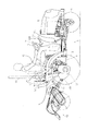
図1には、作業車両の実施例として、作業機としてロータリ耕耘装置を装着したトラクタの左側面図を示し、図2には同じく右側面図を示す。また、図3には図2の昇降シリンダケース部分の詳細図を示し、図4には、制御装置のブロック図を示す。尚、作業車両としては、防除装置、刈草装置等の作業機を装着した作業車両でも良い。 FIG. 1 shows a left side view of a tractor equipped with a rotary tiller as a working machine as an example of a work vehicle, and FIG. 2 shows a right side view of the same. 3 shows a detailed view of the lifting cylinder case portion of FIG. 2, and FIG. 4 shows a block diagram of the control device. The work vehicle may be a work vehicle equipped with a work machine such as a control device or a mowing device.
トラクタは、前輪2、2と後輪3、3を備えた走行車体1の前部にエンジンEを搭載し、その回転動力をミッションケース4内の変速装置によって適宜減速して、これら前輪2、2と後輪3、3に伝えるように構成している。
The tractor has an engine E mounted on the front portion of the traveling vehicle body 1 including the front wheels 2, 2 and the
走行車体1の中央に配置されるハンドルポスト5にはステアリングハンドル6が支持され、その後方には運転席7が設けられている。ステアリングハンドル6の下方には、走行車体1の進行方向を前後方向に切り換える前後進レバー8が設けられている。また、ハンドルポスト5を挟んで前後進レバー8の反対側のステップフロア12の左コーナー部には、クラッチを調節するクラッチペダル9が設けられ、ステップフロア12の右コーナー部には左右の後輪3、3にブレーキを作動させる左右のブレーキペダル10L、10Rが設けられている。
A steering handle 6 is supported on a handle post 5 disposed in the center of the traveling vehicle body 1, and a driver's seat 7 is provided behind the steering handle 6. A forward / reverse lever 8 that switches the traveling direction of the traveling vehicle body 1 to the front-rear direction is provided below the steering handle 6. A
また、主変速装置(図示せず)を中立と1速、2速、3速とに切り換える主変速レバー14は運転席7の左前方部にあり、副変速装置(図示せず)を低速、中速、高速及び中立のいずれかの位置を選択できる副変速レバー16はその後方にあり、更にその後方にはロータリ耕耘装置の回転速度を、低速、中立、高速とに変更するPTO変速レバー17を設けている。これらの変速装置は、ギアなどのメカ機構、油圧クラッチなどの油圧駆動式のものなどがある。
A main transmission lever 14 for switching the main transmission (not shown) between neutral, first speed, second speed, and third speed is located in the left front portion of the driver's seat 7, and the auxiliary transmission (not shown) is operated at a low speed. The auxiliary
更にその右側には作業機22の高さを設定するポジションレバー18などが配置されている。また安全フレーム(ロプスとも言う)19が運転席7の後方に立設されている。
ポジションレバー18の基部には、操作位置を検出するポジションレバーセンサ(ポテンショメータなど)18a(図4)が設けられている。作業機22は、後輪3のアクスルケース23に固着する支持部材25と支持部材25に回動可能に連結する支持アーム27を介して、走行車体1の後部に連結している。また、昇降シリンダ30のピストンロッド30aの先端部には回動アーム32の一端が連結し、回動アーム32の他端は回動アーム軸33に固着している。回動アーム軸33には、リフトアーム50の一端も固着しており、リフトアーム50の他端には、リフトロッド51の一端が回動可能に連結している。また、リフトロッド51の他端は前記支持アーム27に回動可能に連結している。
Further, a position lever 18 for setting the height of the
At the base of the position lever 18, a position lever sensor (potentiometer or the like) 18a (FIG. 4) for detecting the operation position is provided. The
ポジションレバー18を運転者が前方に操作すると、電磁油圧バルブ(昇降ソレノイドバルブ)40の上昇側ソレノイド40aが作動して昇降シリンダケース35内の昇降シリンダ30が伸張し、回動アーム32が回動アーム軸33を回転させることで、リフトアーム50が回動アーム軸33を支点として矢印A方向(上方)に回動し、リフトロッド51及び支持アーム27を介して作業機22が上昇する。同様に、ポジションレバー18を運転者が後方に操作すると、下降側ソレノイド40bが作動して昇降シリンダケース35内の昇降シリンダ30が収縮し、リフトアーム50が回動アーム軸33を支点として矢印A方向とは反対方向(下方)に回動することで、作業機22が下降する。
When the driver operates the position lever 18 forward, the ascending
本実施例のトラクタは、走行車体1の後部に反射材として反射鏡36を立設しており、更に、反射鏡36の下部に、反射鏡36から所定距離(例えば、1m)以内の後方にある遮蔽物の有無を検出する遮蔽物検出センサ60を設置している。
そして、遮蔽物検出センサ60により遮蔽物が有ることが検出されると、反射鏡36が遮蔽状態であることを報知して警告する構成である(報知機能)。反射鏡36は左右フェンダ37,37のどちらか一方の後部に取り付けることで、容易に設置できる。
In the tractor of this embodiment, a reflecting
And when it is detected by the shielding
図5には、遮蔽物センサ60の検出方法を説明する図を示す。
この遮蔽物センサ60は光電センサであり、投光部60aの光が検出物体62に当たり、受光部60bに戻ってくることでオン/オフする構成である。尚、光電センサに限らず、赤外線センサや超音波センサなどを用いても良い。
In FIG. 5, the figure explaining the detection method of the
The
トラクタの路上走行時は作業機22を上昇させるが、その場合に反射鏡36が隠れる高さまで上昇すると、遮蔽物センサ60がオンになり、制御装置100にセンサ信号が入力される。そして、制御装置100からメータパネル63上にある報知ブザー65や報知ランプ67に信号が出力されることで、報知ブザー65が鳴ったり、報知ランプ67が点灯したりする。尚、報知ブザー65と報知ランプ67は両方設けても良いが、どちらか一方でも構わない。また、ブザーやランプに限らず、音声やパネル上に絵や文字が表示されるなど、聴覚又は視覚によって認識できる報知手段であれば良い。
When the tractor travels on the road, the
作業機22を装着した状態でトラクタが路上を走行する際には、反射鏡36を後方から視認できないと危険である。本構成によれば、作業機22の上端が反射鏡36とほぼ同じ高さまで上昇して遮蔽物検出センサ60によって反射鏡36が遮蔽状態であることが検知されると、報知ブザー65や報知ランプ67により、運転者は直ぐに遮蔽状態であることに気がつく。この場合、運転者はポジションレバー18を操作して、作業機22を下げたり、走行を停止して作業機22の位置を確認したりすることが出来る。従って、そのまま走行を継続してしまうことを防止でき、安全性が確保される。
When the tractor travels on the road with the work implement 22 attached, it is dangerous if the reflecting
そして、農業用の作業車両は、一般の自動車と比較して走行速度の遅いものが多く、特に夕方から夜間に掛けては後方から接近する自動車からの認知が遅れやすい。そこで、路上を走行する場合は低速車マークを機体後部に装着して走行することが求められている。 Agricultural work vehicles often have a slower traveling speed than ordinary automobiles, and recognition from automobiles approaching from the rear tends to be delayed particularly from evening to night. Therefore, when traveling on the road, it is required to travel with the low speed vehicle mark attached to the rear of the fuselage.
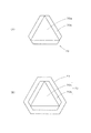
低速車マーク70の正面図を図6(A)に示す。
低速車マーク70は略三角形状であり、三角形状部材70aの周囲に反射板70bが設置されている。後続車両の前照灯により反射板70bの部分が三角形の輪郭として浮かび上がることで、車両の存在が認識される。
A front view of the low-
The low-
そして、図1及び図2に示すように、この低速車マーク70の下部に遮蔽物センサ60を取り付けることで、低速車マーク70が隠れる高さまで作業機22が上昇すると、遮蔽物センサ60がオンになって、制御装置100により報知ブザー65が鳴ったり、報知ランプ67が点灯したりする。従って、低速車マーク70が作業機22によって隠れていることに運転者は直ぐに気がつくため、気づかないままで走行することを防止できる。従って、路上走行時における安全性が確保される。
Then, as shown in FIGS. 1 and 2, when the work implement 22 is raised to a height at which the low
また、低速車マーク70の他の例(正面図)を図6(B)に示す。この例では、低速車マーク70の外形に沿って鉄板のブラケット61を設けている。そのブラケット61に遮蔽物センサ60を取り付けると良い。尚、ブラケット61の素材は鉄ではなく樹脂でも良い。樹脂の方が軽量であり、また温度変化も少ないため、取り扱いやすい。
Another example (front view) of the low-
図7には、ロプス仕様のトラクタの低速車マーク70の設置例を示し、図8には、キャビン仕様のトラクタの低速車マーク70の設置例を示す。各図の(A)は斜視図を示し、(B)はトラクタの一部背面図(低速車マークに関しては正面図)を示している。
FIG. 7 shows an installation example of the low-
これらの図では、ブラケット61に設けた穴(図示せず)又は切り欠きに遮蔽物センサ60をはめ込んでいる。ロプス仕様の場合は、運転席7の後部に設けたホルダ73に低速車マーク70の裏面のブラケット72を差し込むことで、固定される。キャビン仕様の場合も同様に、キャビン75のリアウィンドウ75aに設けたホルダ73に低速車マーク70の裏面のブラケット72を差し込むことで、固定される。
In these drawings, the shielding
また、図1及び図2において、遮蔽物センサ60は反射鏡36の下部と低速車マーク70の下部に取り付けられているが、少なくともいずれか一方の低い方にのみ取り付けても良い。二つ取り付けた場合はどちらか一方でも検知したら報知ブザー65等により警告する構成とする。取り付ける作業機22の形状によっては上側の反射材のみ隠れる可能性がある。また、二つ取り付けた場合、装着できる作業機22には様々な形状のものがあるので、下側の反射材は隠れずに、上側の反射材のみが隠れる場合も想定されるが、この場合の検知漏れを防止できるというメリットがある。
1 and 2, the
更に、報知ブザー65や報知ランプ67による警告後に、運転者がメータパネル63上に設けた遮蔽解除スイッチ77を押すと、遮蔽物を感知しない、即ち遮蔽物センサ60がオフとなる位置まで作業機22を下降させる遮蔽下降機能を制御装置100に設けても良い。
Furthermore, when the driver presses the shielding
遮蔽解除スイッチ77を押すと、スイッチのオン信号が制御装置100に入力され、下降側ソレノイド40bに信号が出力される。この制御は遮蔽物センサ60からのオン信号がオフになるまで継続される。
When the shielding
スイッチ操作という運転者の意思で作業機22を下げることで、作業機22が作動することを運転者自身が認識しているため、自動で作業機22が下降する場合に比べてより安全である。
Since the driver recognizes that the
更に、前記遮蔽解除スイッチ77の操作による作業機22の下降は、主変速レバー14と副変速レバー16とPTO変速レバー17が全て中立である時を条件とすると良い。図9には、この場合の制御フローを示す。
Further, the lowering of the work implement 22 by the operation of the shielding
作業機22が上昇して遮蔽物センサ60が遮蔽物を感知すると、報知ランプ67が点灯し、報知ブザー65が鳴る。ここで運転者が作業機22を下げようとして遮蔽解除スイッチ77を押すと、主変速レバー14と副変速レバー16とPTO変速レバー17の操作位置を判断し、全て中立である場合に、作業機22を下降させる。尚、これらのレバーが全て中立ではない場合は、報知ランプ67が点滅し、報知ブザー65が断続的に鳴るようにすることで、運転者に各レバーの操作位置を確認するように促すことが出来る。
When the
主変速レバー14と副変速レバー16とPTO変速レバー17の操作位置は、各レバーの中立位置に設けた主変速ニュートラルセンサ14a(図4)と副変速ニュートラルセンサ16aとPTOニュートラルセンサ17aからの入力信号の有無で判断される。
The operation positions of the main transmission lever 14, the
走行中に作業機22が作動すると、安全性の点で好ましくない。しかし、主変速レバー14と副変速レバー16とPTO変速レバー17が全て中立である、トラクタの停止時に作業機22の位置を変えることで、路上走行前に作業機22を適切な位置にすることができ、安全性も確保される。
It is not preferable in terms of safety if the work implement 22 operates during traveling. However, by changing the position of the work implement 22 when the main transmission lever 14, the
1 走行車体 2 前輪
3 後輪 4 ミッションケース
5 ハンドルポスト 6 ステアリングハンドル
7 運転席 8 前後進レバー
9 クラッチペダル 10 ブレーキペダル
12 ステップフロア 14 主変速レバー
16 副変速レバー 17 PTO変速レバー
18 ポジションレバー
19 安全フレーム
22 作業機 23 後輪アクスルケース
25 支持部材 27 支持アーム
30 昇降シリンダ 32 回動アーム
33 回動アーム軸 35 昇降シリンダケース
36 反射鏡 37 フェンダ
40 昇降ソレノイドバルブ
50 リフトアーム 51 リフトロッド
60 遮蔽物検出センサ
61 ブラケット
63 メータパネル 65 報知ブザー
67 報知ランプ 70 低速車マーク
72 ブラケット 73 ホルダ
75 キャビン 75a リアウィンドウ
77 遮蔽解除スイッチ
1 traveling vehicle body 2
Claims (2)
Priority Applications (1)
| Application Number | Priority Date | Filing Date | Title |
|---|---|---|---|
| JP2015246139A JP2017108687A (en) | 2015-12-17 | 2015-12-17 | Work vehicle |
Applications Claiming Priority (1)
| Application Number | Priority Date | Filing Date | Title |
|---|---|---|---|
| JP2015246139A JP2017108687A (en) | 2015-12-17 | 2015-12-17 | Work vehicle |
Publications (1)
| Publication Number | Publication Date |
|---|---|
| JP2017108687A true JP2017108687A (en) | 2017-06-22 |
Family
ID=59079076
Family Applications (1)
| Application Number | Title | Priority Date | Filing Date |
|---|---|---|---|
| JP2015246139A Pending JP2017108687A (en) | 2015-12-17 | 2015-12-17 | Work vehicle |
Country Status (1)
| Country | Link |
|---|---|
| JP (1) | JP2017108687A (en) |
Cited By (3)
| Publication number | Priority date | Publication date | Assignee | Title |
|---|---|---|---|---|
| JP2021006014A (en) * | 2019-06-27 | 2021-01-21 | 井関農機株式会社 | Work vehicle |
| JP2021007305A (en) * | 2019-06-28 | 2021-01-28 | 井関農機株式会社 | Work vehicle |
| JP2021007306A (en) * | 2019-06-28 | 2021-01-28 | 井関農機株式会社 | Work vehicle |
-
2015
- 2015-12-17 JP JP2015246139A patent/JP2017108687A/en active Pending
Cited By (6)
| Publication number | Priority date | Publication date | Assignee | Title |
|---|---|---|---|---|
| JP2021006014A (en) * | 2019-06-27 | 2021-01-21 | 井関農機株式会社 | Work vehicle |
| JP7196786B2 (en) | 2019-06-27 | 2022-12-27 | 井関農機株式会社 | work vehicle |
| JP2021007305A (en) * | 2019-06-28 | 2021-01-28 | 井関農機株式会社 | Work vehicle |
| JP2021007306A (en) * | 2019-06-28 | 2021-01-28 | 井関農機株式会社 | Work vehicle |
| JP7226143B2 (en) | 2019-06-28 | 2023-02-21 | 井関農機株式会社 | work vehicle |
| JP7234828B2 (en) | 2019-06-28 | 2023-03-08 | 井関農機株式会社 | work vehicle |
Similar Documents
| Publication | Publication Date | Title |
|---|---|---|
| CN111319674B (en) | Vehicle with a steering wheel | |
| JP6898055B1 (en) | Vehicle approach notification device and picking truck equipped with the device | |
| US11702135B2 (en) | Work vehicle | |
| JP2017108687A (en) | Work vehicle | |
| JP6846375B2 (en) | Rolling machine | |
| JP5560844B2 (en) | Driving device for automatic steering of traveling vehicle | |
| JP2011111022A (en) | Working vehicle | |
| CN105522917A (en) | Driving safety device of vehicle | |
| JP7017293B2 (en) | Vehicle approach notification device and forklift equipped with the device | |
| JP5260929B2 (en) | Work vehicle | |
| KR101984133B1 (en) | Kickboard with improved safety | |
| US10759337B2 (en) | Work vehicle | |
| JP2021004586A (en) | Work vehicle | |
| JP6634865B2 (en) | Work vehicle | |
| JP2022170403A (en) | work vehicle | |
| JP2011246041A (en) | Work vehicle | |
| JP2022178345A (en) | work vehicle | |
| JP7036526B1 (en) | Vehicle approach notification device and picking truck equipped with the device | |
| JP2021078426A (en) | Working vehicle | |
| JP2014132856A (en) | Work vehicle | |
| JP2013029069A (en) | Working vehicle | |
| JP2022178350A (en) | Automatically steered work vehicle | |
| JP3737243B2 (en) | Work vehicle | |
| JP2024050538A (en) | Work vehicles | |
| JP6634866B2 (en) | Work vehicle |