JP2017106906A - Radio wave transmission cover with metallic luster - Google Patents
Radio wave transmission cover with metallic luster Download PDFInfo
- Publication number
- JP2017106906A JP2017106906A JP2016221298A JP2016221298A JP2017106906A JP 2017106906 A JP2017106906 A JP 2017106906A JP 2016221298 A JP2016221298 A JP 2016221298A JP 2016221298 A JP2016221298 A JP 2016221298A JP 2017106906 A JP2017106906 A JP 2017106906A
- Authority
- JP
- Japan
- Prior art keywords
- layer
- radio wave
- optical film
- multilayer optical
- wave transmission
- Prior art date
- Legal status (The legal status is an assumption and is not a legal conclusion. Google has not performed a legal analysis and makes no representation as to the accuracy of the status listed.)
- Pending
Links
Images


Classifications
-
- G—PHYSICS
- G02—OPTICS
- G02B—OPTICAL ELEMENTS, SYSTEMS OR APPARATUS
- G02B5/00—Optical elements other than lenses
- G02B5/08—Mirrors
- G02B5/0816—Multilayer mirrors, i.e. having two or more reflecting layers
-
- G—PHYSICS
- G02—OPTICS
- G02B—OPTICAL ELEMENTS, SYSTEMS OR APPARATUS
- G02B1/00—Optical elements characterised by the material of which they are made; Optical coatings for optical elements
- G02B1/10—Optical coatings produced by application to, or surface treatment of, optical elements
- G02B1/14—Protective coatings, e.g. hard coatings
-
- B—PERFORMING OPERATIONS; TRANSPORTING
- B60—VEHICLES IN GENERAL
- B60R—VEHICLES, VEHICLE FITTINGS, OR VEHICLE PARTS, NOT OTHERWISE PROVIDED FOR
- B60R19/00—Wheel guards; Radiator guards, e.g. grilles; Obstruction removers; Fittings damping bouncing force in collisions
- B60R19/52—Radiator or grille guards ; Radiator grilles
-
- B—PERFORMING OPERATIONS; TRANSPORTING
- B60—VEHICLES IN GENERAL
- B60W—CONJOINT CONTROL OF VEHICLE SUB-UNITS OF DIFFERENT TYPE OR DIFFERENT FUNCTION; CONTROL SYSTEMS SPECIALLY ADAPTED FOR HYBRID VEHICLES; ROAD VEHICLE DRIVE CONTROL SYSTEMS FOR PURPOSES NOT RELATED TO THE CONTROL OF A PARTICULAR SUB-UNIT
- B60W30/00—Purposes of road vehicle drive control systems not related to the control of a particular sub-unit, e.g. of systems using conjoint control of vehicle sub-units
- B60W30/14—Adaptive cruise control
- B60W30/143—Speed control
-
- C—CHEMISTRY; METALLURGY
- C23—COATING METALLIC MATERIAL; COATING MATERIAL WITH METALLIC MATERIAL; CHEMICAL SURFACE TREATMENT; DIFFUSION TREATMENT OF METALLIC MATERIAL; COATING BY VACUUM EVAPORATION, BY SPUTTERING, BY ION IMPLANTATION OR BY CHEMICAL VAPOUR DEPOSITION, IN GENERAL; INHIBITING CORROSION OF METALLIC MATERIAL OR INCRUSTATION IN GENERAL
- C23C—COATING METALLIC MATERIAL; COATING MATERIAL WITH METALLIC MATERIAL; SURFACE TREATMENT OF METALLIC MATERIAL BY DIFFUSION INTO THE SURFACE, BY CHEMICAL CONVERSION OR SUBSTITUTION; COATING BY VACUUM EVAPORATION, BY SPUTTERING, BY ION IMPLANTATION OR BY CHEMICAL VAPOUR DEPOSITION, IN GENERAL
- C23C14/00—Coating by vacuum evaporation, by sputtering or by ion implantation of the coating forming material
- C23C14/0015—Coating by vacuum evaporation, by sputtering or by ion implantation of the coating forming material characterized by the colour of the layer
-
- C—CHEMISTRY; METALLURGY
- C23—COATING METALLIC MATERIAL; COATING MATERIAL WITH METALLIC MATERIAL; CHEMICAL SURFACE TREATMENT; DIFFUSION TREATMENT OF METALLIC MATERIAL; COATING BY VACUUM EVAPORATION, BY SPUTTERING, BY ION IMPLANTATION OR BY CHEMICAL VAPOUR DEPOSITION, IN GENERAL; INHIBITING CORROSION OF METALLIC MATERIAL OR INCRUSTATION IN GENERAL
- C23C—COATING METALLIC MATERIAL; COATING MATERIAL WITH METALLIC MATERIAL; SURFACE TREATMENT OF METALLIC MATERIAL BY DIFFUSION INTO THE SURFACE, BY CHEMICAL CONVERSION OR SUBSTITUTION; COATING BY VACUUM EVAPORATION, BY SPUTTERING, BY ION IMPLANTATION OR BY CHEMICAL VAPOUR DEPOSITION, IN GENERAL
- C23C14/00—Coating by vacuum evaporation, by sputtering or by ion implantation of the coating forming material
- C23C14/02—Pretreatment of the material to be coated
- C23C14/021—Cleaning or etching treatments
- C23C14/022—Cleaning or etching treatments by means of bombardment with energetic particles or radiation
-
- C—CHEMISTRY; METALLURGY
- C23—COATING METALLIC MATERIAL; COATING MATERIAL WITH METALLIC MATERIAL; CHEMICAL SURFACE TREATMENT; DIFFUSION TREATMENT OF METALLIC MATERIAL; COATING BY VACUUM EVAPORATION, BY SPUTTERING, BY ION IMPLANTATION OR BY CHEMICAL VAPOUR DEPOSITION, IN GENERAL; INHIBITING CORROSION OF METALLIC MATERIAL OR INCRUSTATION IN GENERAL
- C23C—COATING METALLIC MATERIAL; COATING MATERIAL WITH METALLIC MATERIAL; SURFACE TREATMENT OF METALLIC MATERIAL BY DIFFUSION INTO THE SURFACE, BY CHEMICAL CONVERSION OR SUBSTITUTION; COATING BY VACUUM EVAPORATION, BY SPUTTERING, BY ION IMPLANTATION OR BY CHEMICAL VAPOUR DEPOSITION, IN GENERAL
- C23C14/00—Coating by vacuum evaporation, by sputtering or by ion implantation of the coating forming material
- C23C14/06—Coating by vacuum evaporation, by sputtering or by ion implantation of the coating forming material characterised by the coating material
- C23C14/08—Oxides
- C23C14/083—Oxides of refractory metals or yttrium
-
- C—CHEMISTRY; METALLURGY
- C23—COATING METALLIC MATERIAL; COATING MATERIAL WITH METALLIC MATERIAL; CHEMICAL SURFACE TREATMENT; DIFFUSION TREATMENT OF METALLIC MATERIAL; COATING BY VACUUM EVAPORATION, BY SPUTTERING, BY ION IMPLANTATION OR BY CHEMICAL VAPOUR DEPOSITION, IN GENERAL; INHIBITING CORROSION OF METALLIC MATERIAL OR INCRUSTATION IN GENERAL
- C23C—COATING METALLIC MATERIAL; COATING MATERIAL WITH METALLIC MATERIAL; SURFACE TREATMENT OF METALLIC MATERIAL BY DIFFUSION INTO THE SURFACE, BY CHEMICAL CONVERSION OR SUBSTITUTION; COATING BY VACUUM EVAPORATION, BY SPUTTERING, BY ION IMPLANTATION OR BY CHEMICAL VAPOUR DEPOSITION, IN GENERAL
- C23C14/00—Coating by vacuum evaporation, by sputtering or by ion implantation of the coating forming material
- C23C14/06—Coating by vacuum evaporation, by sputtering or by ion implantation of the coating forming material characterised by the coating material
- C23C14/08—Oxides
- C23C14/086—Oxides of zinc, germanium, cadmium, indium, tin, thallium or bismuth
-
- C—CHEMISTRY; METALLURGY
- C23—COATING METALLIC MATERIAL; COATING MATERIAL WITH METALLIC MATERIAL; CHEMICAL SURFACE TREATMENT; DIFFUSION TREATMENT OF METALLIC MATERIAL; COATING BY VACUUM EVAPORATION, BY SPUTTERING, BY ION IMPLANTATION OR BY CHEMICAL VAPOUR DEPOSITION, IN GENERAL; INHIBITING CORROSION OF METALLIC MATERIAL OR INCRUSTATION IN GENERAL
- C23C—COATING METALLIC MATERIAL; COATING MATERIAL WITH METALLIC MATERIAL; SURFACE TREATMENT OF METALLIC MATERIAL BY DIFFUSION INTO THE SURFACE, BY CHEMICAL CONVERSION OR SUBSTITUTION; COATING BY VACUUM EVAPORATION, BY SPUTTERING, BY ION IMPLANTATION OR BY CHEMICAL VAPOUR DEPOSITION, IN GENERAL
- C23C14/00—Coating by vacuum evaporation, by sputtering or by ion implantation of the coating forming material
- C23C14/06—Coating by vacuum evaporation, by sputtering or by ion implantation of the coating forming material characterised by the coating material
- C23C14/10—Glass or silica
-
- C—CHEMISTRY; METALLURGY
- C23—COATING METALLIC MATERIAL; COATING MATERIAL WITH METALLIC MATERIAL; CHEMICAL SURFACE TREATMENT; DIFFUSION TREATMENT OF METALLIC MATERIAL; COATING BY VACUUM EVAPORATION, BY SPUTTERING, BY ION IMPLANTATION OR BY CHEMICAL VAPOUR DEPOSITION, IN GENERAL; INHIBITING CORROSION OF METALLIC MATERIAL OR INCRUSTATION IN GENERAL
- C23C—COATING METALLIC MATERIAL; COATING MATERIAL WITH METALLIC MATERIAL; SURFACE TREATMENT OF METALLIC MATERIAL BY DIFFUSION INTO THE SURFACE, BY CHEMICAL CONVERSION OR SUBSTITUTION; COATING BY VACUUM EVAPORATION, BY SPUTTERING, BY ION IMPLANTATION OR BY CHEMICAL VAPOUR DEPOSITION, IN GENERAL
- C23C14/00—Coating by vacuum evaporation, by sputtering or by ion implantation of the coating forming material
- C23C14/22—Coating by vacuum evaporation, by sputtering or by ion implantation of the coating forming material characterised by the process of coating
- C23C14/24—Vacuum evaporation
- C23C14/28—Vacuum evaporation by wave energy or particle radiation
- C23C14/30—Vacuum evaporation by wave energy or particle radiation by electron bombardment
-
- G—PHYSICS
- G01—MEASURING; TESTING
- G01S—RADIO DIRECTION-FINDING; RADIO NAVIGATION; DETERMINING DISTANCE OR VELOCITY BY USE OF RADIO WAVES; LOCATING OR PRESENCE-DETECTING BY USE OF THE REFLECTION OR RERADIATION OF RADIO WAVES; ANALOGOUS ARRANGEMENTS USING OTHER WAVES
- G01S13/00—Systems using the reflection or reradiation of radio waves, e.g. radar systems; Analogous systems using reflection or reradiation of waves whose nature or wavelength is irrelevant or unspecified
- G01S13/88—Radar or analogous systems specially adapted for specific applications
- G01S13/93—Radar or analogous systems specially adapted for specific applications for anti-collision purposes
- G01S13/931—Radar or analogous systems specially adapted for specific applications for anti-collision purposes of land vehicles
-
- H—ELECTRICITY
- H01—ELECTRIC ELEMENTS
- H01Q—ANTENNAS, i.e. RADIO AERIALS
- H01Q1/00—Details of, or arrangements associated with, antennas
- H01Q1/27—Adaptation for use in or on movable bodies
- H01Q1/32—Adaptation for use in or on road or rail vehicles
- H01Q1/3208—Adaptation for use in or on road or rail vehicles characterised by the application wherein the antenna is used
- H01Q1/3233—Adaptation for use in or on road or rail vehicles characterised by the application wherein the antenna is used particular used as part of a sensor or in a security system, e.g. for automotive radar, navigation systems
-
- H—ELECTRICITY
- H01—ELECTRIC ELEMENTS
- H01Q—ANTENNAS, i.e. RADIO AERIALS
- H01Q1/00—Details of, or arrangements associated with, antennas
- H01Q1/42—Housings not intimately mechanically associated with radiating elements, e.g. radome
-
- B—PERFORMING OPERATIONS; TRANSPORTING
- B60—VEHICLES IN GENERAL
- B60R—VEHICLES, VEHICLE FITTINGS, OR VEHICLE PARTS, NOT OTHERWISE PROVIDED FOR
- B60R19/00—Wheel guards; Radiator guards, e.g. grilles; Obstruction removers; Fittings damping bouncing force in collisions
- B60R19/52—Radiator or grille guards ; Radiator grilles
- B60R2019/525—Radiator grilles
-
- G—PHYSICS
- G01—MEASURING; TESTING
- G01S—RADIO DIRECTION-FINDING; RADIO NAVIGATION; DETERMINING DISTANCE OR VELOCITY BY USE OF RADIO WAVES; LOCATING OR PRESENCE-DETECTING BY USE OF THE REFLECTION OR RERADIATION OF RADIO WAVES; ANALOGOUS ARRANGEMENTS USING OTHER WAVES
- G01S13/00—Systems using the reflection or reradiation of radio waves, e.g. radar systems; Analogous systems using reflection or reradiation of waves whose nature or wavelength is irrelevant or unspecified
- G01S13/88—Radar or analogous systems specially adapted for specific applications
-
- G—PHYSICS
- G01—MEASURING; TESTING
- G01S—RADIO DIRECTION-FINDING; RADIO NAVIGATION; DETERMINING DISTANCE OR VELOCITY BY USE OF RADIO WAVES; LOCATING OR PRESENCE-DETECTING BY USE OF THE REFLECTION OR RERADIATION OF RADIO WAVES; ANALOGOUS ARRANGEMENTS USING OTHER WAVES
- G01S7/00—Details of systems according to groups G01S13/00, G01S15/00, G01S17/00
- G01S7/02—Details of systems according to groups G01S13/00, G01S15/00, G01S17/00 of systems according to group G01S13/00
- G01S7/027—Constructional details of housings, e.g. form, type, material or ruggedness
Landscapes
- Chemical & Material Sciences (AREA)
- Engineering & Computer Science (AREA)
- Mechanical Engineering (AREA)
- Organic Chemistry (AREA)
- Chemical Kinetics & Catalysis (AREA)
- Materials Engineering (AREA)
- Metallurgy (AREA)
- Physics & Mathematics (AREA)
- Radar, Positioning & Navigation (AREA)
- Remote Sensing (AREA)
- General Physics & Mathematics (AREA)
- Optics & Photonics (AREA)
- Computer Networks & Wireless Communication (AREA)
- Health & Medical Sciences (AREA)
- Toxicology (AREA)
- Computer Security & Cryptography (AREA)
- Electromagnetism (AREA)
- Transportation (AREA)
- Automation & Control Theory (AREA)
- Laminated Bodies (AREA)
- Details Of Aerials (AREA)
- Radar Systems Or Details Thereof (AREA)
Abstract
【課題】電波透過性を維持しながら金属質感を実現し、より安価な材料で製造することができる電波透過型カバーを提供する。【解決手段】自動車のフロントグリルに設置されてレーダー電波を透過させる、金属光沢を有する電波透過型カバーは、前記フロントグリルの前方表面に晒される透明なレジン層10、前記レジン層10の後方に形成され、互いに異なる屈折率を有する金属酸化物が交互に積層された多層光学膜層30aとゲルマニウム層40aから構成される金属質感層100a、および前記金属質感層100aの後方に形成され、前記金属質感層100aの反射率を向上させる不透明層50を含む。前記多層光学膜層30aは、高屈折率層と、低屈折率層とを交互に積層して構成され、前記多層光学膜層30aを構成する層のうち前記レジン層10に最も近い層は、高屈折率層であることを特徴とする。【選択図】図2An object of the present invention is to provide a radio wave transmission type cover that realizes a metallic texture while maintaining radio wave transmissivity and can be manufactured from a less expensive material. A radio wave transmissive cover having a metallic luster that is installed on a front grill of an automobile and transmits a radar radio wave is a transparent resin layer that is exposed to a front surface of the front grill, and a rear side of the resin layer. A metal texture layer 100a composed of a multilayer optical film layer 30a and a germanium layer 40a formed by alternately stacking metal oxides having different refractive indexes, and formed behind the metal texture layer 100a. It includes an opaque layer 50 that improves the reflectance of the texture layer 100a. The multilayer optical film layer 30a is configured by alternately laminating high refractive index layers and low refractive index layers, and a layer closest to the resin layer 10 among the layers constituting the multilayer optical film layer 30a is: It is a high refractive index layer. [Selection] Figure 2
Description
本発明は、金属光沢を有する電波透過型カバーに係り、より詳しくは、SCCレーダーを保護し且つ電波を透過させる、金属光沢を有する電波透過型カバーに関する。 The present invention relates to a radio wave transmissive cover having a metallic luster, and more particularly to a radio wave transmissive cover having a metallic luster that protects an SCC radar and transmits radio waves.
スマートクルーズコントロール(SCC)システムは、車両の前方に装着されたレーダーによって先行車の動きを感知し、これによりエンジンとブレーキを制御して先行車との距離を維持するシステムである。
このシステムの核心となるSCCレーダーは、車両の前方中央に設置することが性能確保の面で最も有利であるが、このような車両の前方中央には、通常、ラジエーターグリルや、自動車メーカーのエンブレム(emblem)または装飾物などが位置することが多い。
通常、ラジエーターグリルは、金属で製造され、腐食を防止するためにクロムでメッキされる。
ところが、金属は、電波透過性が低いため、SCCレーダーの電波送受信に悪影響を及ぼす。よって、電波送受信がスムーズに行われるようにラジエーターグリルの一部の領域を別のレーダーカバーに置き換えて電波透過性を確保する方法が試みられている。
しかし、レーダーカバーは、電波透過性を確保するために金属を排除して製造されるため、金属で製造されたラジエーターグリルとのデザイン的連続性を失ってしまうという問題がある。これを解決するために、従来のレーダーカバーの一部分に電波透過性に優れたインジウムまたはスズを適用して金属質感を実現する技術が開発されてきた。
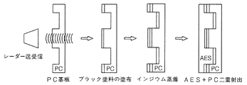
図1に示すように、従来のSCCカバーは、PC材質の透明層に金属質感を示す部分のみを晒すためのブラック塗料を塗布し、ここにインジウムを蒸着した後、後面にAES材質を用いて二重射出することにより製造された。
ところが、インジウムやスズが比較的高価な素材なので、レーダーユニット全体の価格が上昇し、素材の融点が低いため、自動車のエンジンに隣接した環境特性上、カバーの耐久性が低下することがあるという問題点があった。
A smart cruise control (SCC) system is a system that senses the movement of a preceding vehicle by a radar mounted in front of the vehicle, thereby controlling the engine and brake to maintain the distance from the preceding vehicle.
The SCC radar, which is the core of this system, is the most advantageous in terms of ensuring performance when installed in the center of the front of the vehicle, but usually in the center of the front of such a vehicle is a radiator grill or an emblem of an automobile manufacturer. (Emblem) or ornaments are often located.
Usually, the radiator grill is made of metal and plated with chrome to prevent corrosion.
However, since metal has low radio wave permeability, it adversely affects radio wave transmission / reception of the SCC radar. Therefore, a method has been attempted in which a part of the radiator grille is replaced with another radar cover to ensure radio wave transmission so that radio wave transmission and reception can be performed smoothly.
However, since the radar cover is manufactured by removing metal in order to ensure radio wave transmission, there is a problem that the design continuity with a radiator grill made of metal is lost. In order to solve this problem, a technique for realizing a metal texture by applying indium or tin with excellent radio wave transmission to a part of a conventional radar cover has been developed.
As shown in FIG. 1, in the conventional SCC cover, a black paint for exposing only a portion showing a metallic texture is applied to a transparent layer of PC material, and after depositing indium, an AES material is used on the rear surface. Manufactured by double injection.
However, since indium and tin are relatively expensive materials, the price of the entire radar unit increases, and the melting point of the materials is low, so the durability of the cover may decrease due to environmental characteristics adjacent to the engine of the car. There was a problem.
本発明は、かかる問題点を解決するためになされたものであって、その目的とするところは、高温で熱変形が発生せず、電波透過性を維持しながら金属質感を実現し、より安価な材料で製造することができる、金属光沢を有する電波透過型カバーを提供することにある。 The present invention has been made to solve such problems, and the object of the present invention is to realize a metal texture while maintaining radio wave permeability without causing thermal deformation at a high temperature, and more inexpensively. An object of the present invention is to provide a radio wave transmission type cover having a metallic luster, which can be manufactured from any material.
上記目的を達成するためになされた本発明の金属光沢を有する電波透過型カバーは、自動車のフロントグリルに設置されてレーダー電波を透過させる金属光沢を有する電波透過型カバーであって、前記フロントグリルの前方表面に晒される透明なレジン層、前記レジン層の後方に形成され、互いに異なる屈折率を有する金属酸化物が交互に積層された多層光学膜層とゲルマニウム(Ge)層から構成されて金属質感の反射光を示す金属質感層、および前記金属質感層の後方に形成され、前記金属質感層の反射率を向上させる不透明層を含むことを特徴とする。 The radio wave transmissive cover with metallic luster of the present invention made to achieve the above object is a radio wave transmissive cover with metallic luster that is installed on a front grill of an automobile and transmits radar radio waves, and the front grill A transparent resin layer that is exposed to the front surface of the metal, and is composed of a multilayer optical film layer and a germanium (Ge) layer formed by alternately stacking metal oxides having different refractive indexes formed behind the resin layer. It includes a metal texture layer showing textured reflected light and an opaque layer formed behind the metal texture layer and improving the reflectance of the metal texture layer.
前記多層光学膜層は、TiO2およびCr2O3のいずれか一つからなる高屈折率層と、SiO2からなる低屈折率層とを交互に積層して構成され、前記多層光学膜層を構成する層のうち前記レジン層に最も近い層は、TiO2からなる高屈折率層であることを特徴とする。 The multilayer optical film layer is configured by alternately stacking a high refractive index layer made of any one of TiO 2 and Cr 2 O 3 and a low refractive index layer made of SiO 2 , and the multilayer optical film layer The layer closest to the resin layer among the layers constituting is a high refractive index layer made of TiO 2 .
前記金属質感層は、可視光線領域(波長400〜700nm)での反射率が30%以上であり、可視光線領域での反射率の偏差が5%P以下であることを特徴とする。 The metal texture layer has a reflectance in the visible light region (wavelength 400 to 700 nm) of 30% or more, and a deviation in reflectance in the visible light region is 5% P or less.
前記高屈折率層および前記低屈折率層はそれぞれ10〜200nmの厚さに形成され、前記多層光学膜層は3層以上に形成されて総厚さが300nm〜10μmであることを特徴とする。 The high refractive index layer and the low refractive index layer are each formed in a thickness of 10 to 200 nm, and the multilayer optical film layer is formed in three or more layers, and the total thickness is 300 nm to 10 μm. .
前記ゲルマニウム層は、前記多層光学膜層の前方に接する面、前記多層光学膜層の後方に接する面、および互いに交互に積層された高屈折率層と低屈折率層との間の面の中から選択された少なくとも一つの位置に形成されることを特徴とする。 The germanium layer includes a surface in contact with the front of the multilayer optical film layer, a surface in contact with the back of the multilayer optical film layer, and a surface between the high refractive index layer and the low refractive index layer that are alternately stacked. It is formed in at least one position selected from the above.
前記ゲルマニウム層は総厚さが50nm〜5μmであることを特徴とする。 The germanium layer has a total thickness of 50 nm to 5 μm.
前記レジン層は、凹凸のない平面または曲面状の前面と、凹部と凸部が形成されて屈曲した後面とを有することを特徴とする。 The resin layer has a flat or curved front surface without unevenness, and a rear surface that is bent with concave portions and convex portions.
前記レジン層と前記金属質感層との間に形成されたプライマー層をさらに含むことを特徴とする。 It further includes a primer layer formed between the resin layer and the metal texture layer.
前記レジン層と前記金属質感層との間に形成され、前記金属質感層の一部を覆うマスキング層をさらに含み、前記マスキング層は、所定の形状を示す部位を除いた残りの部位を覆う不透明な塗料であることを特徴とする。 A masking layer formed between the resin layer and the metal texture layer and covering a part of the metal texture layer is further included, and the masking layer is opaque covering a remaining portion excluding a portion having a predetermined shape. It is a characteristic paint.
本発明による金属光沢を有する電波透過型カバーによれば、次の効果がある。
第一に、セラミックたる金属酸化物および半導体たるゲルマニウムを適用して、レーダーカバーに金属質感の反射光を実現することができる。
第二に、レーダーカバーに適用されるセラミックと半導体の高い電波透過性を用いてSCCレーダーの電波送受信を円滑にすることができる。
第三に、融点の高い金属酸化物とゲルマニウムを用いて、高温での熱変形を防止することができる。
第四に、自動車のラジエーターグリルと類似する金属質感の反射光を提供して自動車外観の連続性および一貫性を維持することができる。
第五に、屈曲して立体的な形状を有しても一定以上の反射率と一定以下の偏差を維持して無彩色の金属質感を実現することができる。
The radio wave transmission type cover having metallic luster according to the present invention has the following effects.
First, by applying ceramic oxide, which is a ceramic, and germanium, which is a semiconductor, it is possible to realize reflected light with a metallic texture on a radar cover.
Secondly, the radio wave transmission / reception of the SCC radar can be facilitated by using the high radio wave permeability of the ceramic and semiconductor applied to the radar cover.
Third, thermal deformation at a high temperature can be prevented by using a metal oxide and germanium having a high melting point.
Fourth, it can provide a metal-like reflected light similar to a car radiator grill to maintain continuity and consistency of the car appearance.
Fifth, even if it is bent and has a three-dimensional shape, an achromatic metal texture can be realized while maintaining a certain reflectance and a certain deviation.
以下、添付図面を参照して、本発明の好適な実施例に係る金属光沢を有する電波透過型カバーについて説明する。
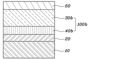
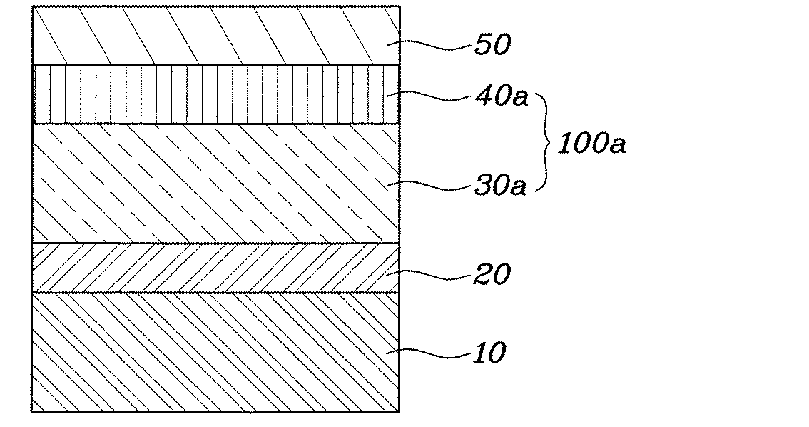
図2は本発明の一実施例を簡略に示す断面図である。図示の如く、本発明に係る金属光沢を有する電波透過型カバーは、大きくは、透明なレジン層10、金属質感の反射光を示すことができる金属質感層100a、および金属質感層100aの反射率を向上させる不透明層50を含んで構成される。ここで、レジン層10と金属質感層100aとの間にプライマー層20をさらに含むことができる。
レジン層10は、透明なプラスチック、例えばポリカーボネート、アクリル樹脂などで形成される層であって、本発明に係るカバーの最外郭部分、すなわち車両の前方表面をなす構成である。
この際、レジン層10が透明に形成されることにより、金属質感層100aを保護しながら外部の光を金属質感層100aに伝達したり、金属質感層100aから反射される金属質感の反射光を外部に伝達したりすることができる。
レジン層10の前面は、屈曲なく滑らかな平面あるいは曲面状に形成され、レジン層10の後面は凹凸が形成されて屈曲している。このとき、後面の屈曲形状は、周囲のラジエーターグリルや自動車メーカーのエンブレム、象徴物などの形状と連続性を有する形状に形成されることが好ましい。
Hereinafter, a radio wave transmission cover having a metallic luster according to a preferred embodiment of the present invention will be described with reference to the accompanying drawings.
FIG. 2 is a sectional view schematically showing an embodiment of the present invention. As shown in the figure, the radio wave transmissive cover having a metallic luster according to the present invention is roughly composed of a
The
At this time, since the
The front surface of the
レジン層10の後面の屈曲面に金属質感層100aが形成されると、所望の形状の立体的な金属質感反射光領域を得ることができる。
金属質感層100aは多層光学膜層30aとゲルマニウム層40aに区分されるが、多層光学膜層30aは互いに異なる屈折率を示す金属酸化物、すなわち、セラミックを交互に積層したものであり、ゲルマニウム層40aは半導体たるゲルマニウム(Ge)で形成された層である。
こうして形成された金属質感層100aは、金属質感の反射光を示すことができるとともに、一般金属に比べて電気伝導度が低いため、高い電波透過性を示す。
金属質感層100aの構成のうち、多層光学膜層30aは、屈折率の高い材料、例えばTiO2、Cr2O3などで形成された高屈折率層と、屈折率の低い材料、例えばSiO2で形成された低屈折率層とを交互に積層して構成することが好ましい。このように高屈折率層と低屈折率層とを交互に積層すると、可視光線領域での反射率が一定に維持されて無彩色の金属質感反射光を得ることができる。
When the
The
The
Among the structures of the
多層光学膜層30aを構成するにあたり、特にレジン層10から最も近い位置には、TiO2からなる高屈折率層を配置することが好ましい。これは、TiO2の接着力が他の材料に比べて高いため、レジン層10にTiO2を最初に積層させると、レジン層10と多層光学膜層30a間の剥離現象が発生する可能性を下げるためである。SiO2は、硬度が高いため、多層光学膜層30aの耐スクラッチ性を確保するのに必要であり、低屈折材料として金属特有の反射光を再現するのに役立つ。
多層光学膜層30aの高屈折率層と低屈折率層は、それぞれの厚さを10〜200nmの範囲で制御し、その総厚さを300nm〜10μmの範囲で制御するが、層数を3層以上にすると、反射角度による色相の異質感を最小限に抑えながら金属質感反射光を示すことができる。
ゲルマニウム層40aは、多層光学膜層30aから発生する金属性反射光をより強化させるための層である。ゲルマニウムは、それ自体の特性上、暗い色味の金属質感を示すので、多層光学膜層30aとゲルマニウム層40aによって形成された金属質感層100aは、一般的なクロム反射光に比べて若干暗いダーククロム色の金属性反射光を示す。このようなダーククロム色は、部品の外観をより高級に見えるようにするのに役立つ。
In configuring the multilayer
The thickness of the high refractive index layer and the low refractive index layer of the multilayer
The
ゲルマニウム層40aの厚さが10μm以上の場合にはレーダー電波の透過性が著しく低下するので、電波透過性が低下しない5μm以下の厚さに形成することが好ましい。一方、ゲルマニウム層40aの厚さが50nm未満の場合には、多層光学膜層30aから発生する金属質感反射光を強化する効果が期待できない。よって、ゲルマニウム層40aの厚さは50nm〜5μmの範囲にする必要がある。
ゲルマニウム層40aは、多層光学膜層30aの後面、すなわち多層光学膜層30aと不透明層50との間に形成されるが、本発明の他の実施例ではその設置位置が異なってもよい。これについては後述する。
上述した多層光学膜層30aとゲルマニウム層40aで製造された金属質感層100a全体の可視光線反射率は30%以上を満足し且つ可視光線領域での反射率の偏差は5%P以下を満足する場合、異色感(特定の色が目立つ現象)のない金属質感反射光を得ることができる。
前述したとおり、レジン層10の後面は屈曲しており、この屈曲した面に金属質感層100aが形成される。平面に比べて立体的に屈曲されている面では、反射率の偏差によって発生する異色感が発現しやすくなるので、本発明で限定する反射率およびその偏差を満足すれば、レジン層10の後面の屈曲面でも無彩色の金属反射光を示すことができるのである。
When the
The
The visible light reflectance of the entire
As described above, the rear surface of the
不透明層50は、不透明な塗料で形成されるが、好ましくは、黒色の塗料で構成した金属質感層100aの後面に形成される層であって、金属質感層100aの反射率を向上させて高い明度の反射光を発生させるために設置される。
金属質感層100aを形成した後、その後方に不透明層50を形成することにより、金属質感層100aによって実現される金属質感の反射光の明度を向上させるうえ、耐環境性および耐スクラッチ性を確保することができる。
上述した構成に加えて、レジン層10と金属質感層100aとの間にプライマー層20がさらに設置できる。プライマー層20は、金属質感層100aから発生する金属質感の反射光に光沢またはつや消し効果を付与して、より高級感のある外観を示すようにすることができる。
図示してはいないが、レジン層10と多層光学膜層30aとの間には、不透明な塗料、好ましくはブラック塗料で形成されるマスキング層が備えられてもよい。
このようなマスキング層は、多層光学膜層30aの一部分を覆うことにより、金属質感反射光が外部に晒される領域を制限して所定の形状をなすようにすることができる。このような形態はラジエーターグリル、エンブレム、象徴物などに適用できる。前述したレジン層10の屈曲した後面の形状とマスキング層の組み合わせを介して、金属質感反射光が晒される領域を立体的な形状にすることもできる。
The
After forming the
In addition to the configuration described above, a
Although not shown, a masking layer formed of an opaque paint, preferably a black paint, may be provided between the
By covering a part of the multilayer
本発明の実施例では、金属質感反射光が晒される領域を制限するためにマスキング層を使用したが、本発明は、これに限定されず、金属質感層100a自体をエッチングするなどの様々な方法で、金属質感が実現される領域を制限することができる。
本発明に係る金属質感層の積層構造は、図2に示す一実施例に限定されず、図3及び図4に示すように変形してもよい。
すなわち、図3に示すように、レジン層10と多層光学膜層30bとの間にゲルマニウム層40bが形成されて金属質感層100bを構成することもでき、図4に示すように、多層光学膜層30c同士の間にゲルマニウム層40cが形成されて金属質感層100cを構成することもできる。
多層光学膜層30c同士の間にゲルマニウム層40cを形成する場合には、多層光学膜層30cの高屈折率層と低屈折率層との間にゲルマニウム層40cを形成することが好ましい。
本発明において、金属質感層100a、100b、100cを形成する方法は、大きく限定しないが、例えば、PVDまたはPACVD工程を介してレジン層10に蒸着、スパッタリングさせることができる。つまり、真空状態でArガスをプラズマ化させ、バイアス(Bias)を加えてレジン層10の表面、特に後面を洗浄および活性化させることで、母材と蒸着層との密着力を高め、高屈折材料(TiO2、Cr2O3)および低屈折材料(SiO2)の試料に電子ビーム(E−Beam)を照射してレジン層の表面に多層光学膜層30aを形成するか、或いはゲルマニウム(Ge)試料に電子ビームを照射してゲルマニウム層40aを形成することができる。
In the embodiment of the present invention, the masking layer is used to limit the area to which the metal texture reflected light is exposed. However, the present invention is not limited to this, and various methods such as etching the
The laminated structure of the metal texture layer according to the present invention is not limited to the embodiment shown in FIG. 2, and may be modified as shown in FIGS.
That is, as shown in FIG. 3, a
When the
In the present invention, the method of forming the
以下、本発明の様々な実施例の効果について説明する。
一般に、自動車外装品としてのラジエーターグリルはクロムメッキされて使用されている。よって、ラジエーターグリルに類似した金属質感を実現するためには、クロムの反射率に類似した反射率を実現する必要がある。このため、一般なクロムの反射率、従来技術のスズ蒸着層の反射率、本発明の実施例に係る多層光学膜層30aおよびゲルマニウム層40aからなる金属質感層100aの反射率が可視光線領域(波長400〜700nm)で変化する数値をMacleod解析プログラムで計算した結果値を表1に示した。
表1に示す比較例1〜5は、レジン層の上にそれぞれの素材を単層に形成したサンプルであり、実施例1〜4は、図2に示すレジン層10、プライマー層20、多層光学膜層30a、ゲルマニウム層40a、不透明層50の順に製造されたサンプルであって、多層光学膜層30aの層数のみを変えて製造した。
Hereinafter, effects of various embodiments of the present invention will be described.
Generally, a radiator grill as an automobile exterior product is used after being chrome plated. Therefore, in order to realize a metal texture similar to the radiator grill, it is necessary to realize a reflectance similar to the reflectance of chrome. For this reason, the reflectance of the general chromium reflectance, the reflectance of the tin deposition layer of the prior art, and the reflectance of the
Comparative Examples 1 to 5 shown in Table 1 are samples in which the respective materials are formed in a single layer on the resin layer, and Examples 1 to 4 are the
比較例4に示すスズは、反射率の偏差が低くて無彩色の金属質感反射光を発生させることはできるものの、全体反射率が30%を下回って輝度が不足していることが分かる。また、比較例5に示すゲルマニウムは、特有の暗い色によって全体的な反射率が低いことが分かる。
これに対し、多層光学膜層30aの総厚さが300nm以上で層数が3層以上である実施例1〜4は、可視光線領域での反射率が30%以上であるとともに反射率の偏差が5%P以下である条件を満足することが分かる。このとき、多層光学膜層30aの層数が高くなるほど、可視光線領域で全般的な反射率が高くなってより明るい反射光を示すことができ、すべての実施例において反射率の偏差が5%P以下を示して異色感のない金属質感の反射光を示すことができる。
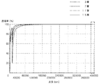
表1の実施例1〜4の電波透過性を測定した結果を図5に示す。多層光学膜層30aの層数が高くなっても、SCCレーダー電波として使用される周波数76〜77GHz、波長40万nmの領域(破線の四角形領域)のレーダー電波透過率が100%に近いことが分かる。これは、多層光学膜層30aが金属酸化物、すなわちセラミック材質であるため、レーダー電波との干渉を起こさないので、その厚さによる電波透過性の差が殆どないからである。
It can be seen that tin shown in Comparative Example 4 has a low reflectance deviation and can generate achromatic metal texture reflected light, but has an overall reflectance of less than 30% and lacks brightness. Moreover, it turns out that germanium shown in Comparative Example 5 has a low overall reflectivity due to a characteristic dark color.
On the other hand, in Examples 1 to 4, in which the total thickness of the multilayer
The result of having measured the radio wave permeability | transmittance of Examples 1-4 of Table 1 is shown in FIG. Even if the number of layers of the multilayer
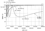
一方、図6に示すように、ゲルマニウム層40aの厚さが5μmを超えて10μmに達すると、周波数76〜77GHz、波長40万nmの領域(破線の四角形領域)のレーダー電波透過率が急激に低くなることが分かる。ゲルマニウムは半導体であるが、一定以上の厚さを有する場合、伝導性が発現されてレーダー電波の透過を妨げるのである。よって、ゲルマニウム層40aの厚さは5μm以下に制限することが好ましい。
本発明によって製造された金属質感層100aサンプルと従来のインジウムコーティングサンプルを製作してレーダー電波減衰率と直進性について測定した結果を表2に示す。
それぞれのサンプルは、厚さ1mmのPC素材板材に対象物を蒸着して製造した。比較例6はインジウム(In)を蒸着し、実施例5〜7はそれぞれゲルマニウム層40aと多層光学膜層30aから構成されるが、多層光学膜層30aの層数を3層、7層、15層に変化させた。
On the other hand, as shown in FIG. 6, when the thickness of the
Table 2 shows the results of measuring the radar radio wave attenuation rate and the straightness of the
Each sample was manufactured by evaporating an object on a PC material plate having a thickness of 1 mm. Comparative Example 6 vapor-deposits indium (In), and Examples 5 to 7 are each composed of a
表2に示すように、実施例5〜7による金属質感層100aサンプルの電波透過性能は、多層光学膜層30aの層数を問わずに、比較例6によるインジウムコーティングサンプルの電波透過性能と同等のレベルを示し、レーダービームの直進性は同等以上の結果を得ることが分かった。
参考までに、本発明に係るカバーに適したレーダー減衰率は、往復基準で−4dB以下(−4〜0dB)、片道基準で−1.8dB以下(−1.8〜0dB)であることが好ましい。
As shown in Table 2, the radio wave transmission performance of the
For reference, the radar attenuation rate suitable for the cover according to the present invention is −4 dB or less (−4 to 0 dB) on a round trip basis and −1.8 dB or less (−1.8 to 0 dB) on a one-way basis. preferable.
それぞれのサンプルに適用された多層光学膜層30a、30b、30cは、5層に同一に形成し、ゲルマニウム層40a、40b、40cの位置のみを多層光学膜層の後面(不透明層方向)、前面(レジン層方向)、中間(高屈折率層と低屈折率層との間)に変更して解析した。
その結果、多層光学膜層30bの後面にゲルマニウム層40bを形成した金属質感層100b、すなわち実施例8が最も高い反射率を示したが、全てのサンプルの可視光線反射率が38〜44%のレベルであって30%以上の反射率を示した。また、全てのサンプルの可視光線領域の反射率偏差が5%P以下を示して無彩色の金属性反射光を示すことが確認できた。
The multilayer
As a result, the
評価結果、表4に示すように、ゲルマニウム層の位置に応じてレーダー電波の減衰率と直進性が大きく変動せずに一定の性能を示すことが確認できた。
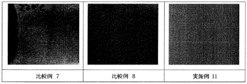
図7には本発明による金属質感層100aのサンプルと、インジウムコーティングおよびゲルマニウムコーティングが施されたサンプルをそれぞれ製造し、その高温耐久性を確認した結果を示す。
それぞれのサンプルはガラス基板に対象物を蒸着させることにより製造された。比較例7はインジウム、比較例8はゲルマニウム、実施例11は多層光学膜層30aおよびゲルマニウム層40aを蒸着させた。その後、高温での耐環境性を測定するために、それぞれのサンプルを220℃で5分間熱処理して蒸着表面の変形程度を確認した。比較例7は表面に多くのクラックが発生するなどの変形が生じたのに対し、比較例8及び実施例11は表面にクラックが発生していないことを確認することができる。
As a result of the evaluation, as shown in Table 4, it was confirmed that the attenuation rate and straightness of the radar radio wave did not vary greatly depending on the position of the germanium layer and showed a certain performance.
FIG. 7 shows the results of manufacturing a
Each sample was manufactured by evaporating an object on a glass substrate. Comparative Example 7 was indium, Comparative Example 8 was germanium, and Example 11 was vapor-deposited with a multilayer
ゲルマニウムのみを使用した比較例8の場合、表面クラックなどの熱変形は起こらなかったが、実施例11に比べて暗い色を示した。これは、先立って表1の比較例5で考察したように、ゲルマニウムの反射率が低いため、反射光の明度が低くなるからである。
In Comparative Example 8 using only germanium, thermal deformation such as surface cracks did not occur, but a darker color was shown compared to Example 11. This is because, as previously discussed in Comparative Example 5 in Table 1, since the reflectivity of germanium is low, the brightness of the reflected light is low.
以上、本発明に関する好適な実施形態を説明したが、本発明は前記実施形態に限定されるものではなく、本発明の属する技術分野を逸脱しない範囲でのすべての変更が含まれる。 As mentioned above, although preferred embodiment regarding this invention was described, this invention is not limited to the said embodiment, All the changes in the range which does not deviate from the technical field to which this invention belongs are included.
10 レジン層
20 プライマー層
30a、30b、30c 多層光学膜層
40a、40b、40c ゲルマニウム層
50 不透明層
100a、100b、100c 金属質感層
10
Claims (9)
前記フロントグリルの前方表面に晒される透明なレジン層、
前記レジン層の後方に形成され、互いに異なる屈折率を有する金属酸化物が交互に積層された多層光学膜層とゲルマニウム(Ge)層から構成されて金属質感の反射光を示す金属質感層、および
前記金属質感層の後方に形成され、前記金属質感層の反射率を向上させる不透明層を含む、金属光沢を有することを特徴とする電波透過型カバー。 A radio wave transmissive cover with a metallic luster that is installed on the front grill of an automobile and transmits radar radio waves.
A transparent resin layer exposed to the front surface of the front grill;
A metal texture layer that is formed behind the resin layer and is composed of a multilayer optical film layer and a germanium (Ge) layer in which metal oxides having different refractive indexes are alternately stacked; A radio wave transmission type cover having a metallic luster, comprising an opaque layer formed behind the metal texture layer and improving the reflectance of the metal texture layer.
前記多層光学膜層を構成する層のうち前記レジン層に最も近い層は、TiO2からなる高屈折率層であることを特徴とする請求項1に記載の金属光沢を有する電波透過型カバー。 The multilayer optical film layer is configured by alternately laminating a high refractive index layer made of any of TiO 2 and Cr 2 O 3 and a low refractive index layer made of SiO 2 ,
2. The radio wave transmission cover with metallic luster according to claim 1, wherein a layer closest to the resin layer among the layers constituting the multilayer optical film layer is a high refractive index layer made of TiO2.
前記多層光学膜層は、3層以上に形成されて総厚さが300nm〜10μmであることを特徴とする請求項2に記載の金属光沢を有する電波透過型カバー。 The high refractive index layer and the low refractive index layer are each formed to a thickness of 10 to 200 nm,
3. The radio wave transmission type cover with metallic luster according to claim 2, wherein the multilayer optical film layer is formed of three or more layers and has a total thickness of 300 nm to 10 [mu] m.
前記マスキング層は、所定の形状を示す部位を除いた残りの部位を覆う不透明な塗料であることを特徴とする請求項1に記載の金属光沢を有する電波透過型カバー。 A masking layer formed between the resin layer and the metal texture layer and covering a part of the metal texture layer;
The radio wave transmission type cover with metallic luster according to claim 1, wherein the masking layer is an opaque paint covering a remaining portion except a portion having a predetermined shape.
Applications Claiming Priority (4)
| Application Number | Priority Date | Filing Date | Title |
|---|---|---|---|
| KR20150175332 | 2015-12-09 | ||
| KR10-2015-0175332 | 2015-12-09 | ||
| KR1020160115705A KR101918351B1 (en) | 2015-12-09 | 2016-09-08 | Cover having metallic luster |
| KR10-2016-0115705 | 2016-09-08 |
Publications (1)
| Publication Number | Publication Date |
|---|---|
| JP2017106906A true JP2017106906A (en) | 2017-06-15 |
Family
ID=57777360
Family Applications (1)
| Application Number | Title | Priority Date | Filing Date |
|---|---|---|---|
| JP2016221298A Pending JP2017106906A (en) | 2015-12-09 | 2016-11-14 | Radio wave transmission cover with metallic luster |
Country Status (4)
| Country | Link |
|---|---|
| US (2) | US10107894B2 (en) |
| EP (1) | EP3181719B1 (en) |
| JP (1) | JP2017106906A (en) |
| CN (1) | CN106908884B (en) |
Cited By (4)
| Publication number | Priority date | Publication date | Assignee | Title |
|---|---|---|---|---|
| KR20190005133A (en) * | 2017-07-05 | 2019-01-15 | 자니니 오토 그룹 에스. 에이 | Radome for vehicles |
| WO2020067052A1 (en) * | 2018-09-25 | 2020-04-02 | 積水化学工業株式会社 | Radio wave permeable body |
| JP2021066022A (en) * | 2019-10-18 | 2021-04-30 | 株式会社ウェーブロック・アドバンスト・テクノロジー | Indium vapor depositing and holding film, metallic multilayer film, method of producing indium vapor depositing and holding film, method of producing metallic multilayer film, and emblem |
| JP2022102455A (en) * | 2020-12-25 | 2022-07-07 | トヨタ自動車株式会社 | Electric wave permeable cover and method for manufacturing the same |
Families Citing this family (21)
| Publication number | Priority date | Publication date | Assignee | Title |
|---|---|---|---|---|
| JP2017106906A (en) * | 2015-12-09 | 2017-06-15 | 現代自動車株式会社Hyundai Motor Company | Radio wave transmission cover with metallic luster |
| JP6677191B2 (en) * | 2017-02-15 | 2020-04-08 | トヨタ自動車株式会社 | Vehicle front structure |
| WO2019221213A1 (en) * | 2018-05-17 | 2019-11-21 | 株式会社イクヨ | Decorative member |
| JP7102947B2 (en) * | 2018-05-29 | 2022-07-20 | トヨタ自動車株式会社 | Sensor protector and vehicle equipped with it |
| US12235389B2 (en) | 2018-08-31 | 2025-02-25 | Magna Electronics Inc. | Automotive radar / LIDAR behind reflective surfaces |
| US10832437B2 (en) * | 2018-09-05 | 2020-11-10 | Rakuten, Inc. | Method and apparatus for assigning image location and direction to a floorplan diagram based on artificial intelligence |
| CN110045510B (en) * | 2018-09-28 | 2020-09-01 | 北京理工大学 | A double fovea stereo imaging system |
| US11092666B2 (en) * | 2018-10-22 | 2021-08-17 | Toyoda Gosei Co., Ltd. | Millimeter wave radar unit and mounting method therefor |
| CN109655954B (en) * | 2019-03-05 | 2024-04-16 | 浙江水晶光电科技股份有限公司 | Optical filter, preparation method thereof, fingerprint identification module and electronic equipment |
| EP3956943A1 (en) | 2019-04-18 | 2022-02-23 | SRG Global, LLC | Stepped radar cover and method of manufacture |
| DE102019129885B4 (en) * | 2019-11-06 | 2022-08-25 | Webasto SE | Roof module with roof skin and surroundings sensor |
| EP4113738A4 (en) * | 2020-02-27 | 2023-11-22 | Zanini Auto Grup, S.A. | DECORATIVE ELEMENT FOR CAMERA VEHICLE |
| EP3958397B1 (en) * | 2020-08-17 | 2023-06-21 | Zanini Auto Grup, S.A. | Radome for vehicles |
| FR3116909B1 (en) * | 2020-12-01 | 2022-12-02 | Valeo Vision | Vehicle assembly comprising a radar sensor and an arrangement of layers forming a logo |
| FR3116907B1 (en) * | 2020-12-01 | 2022-12-09 | Valeo Vision | Vehicle assembly including radar sensor and layer arrangement |
| CN116685862B (en) * | 2020-12-25 | 2026-03-17 | 日东电工株式会社 | Electron wave scatterer and components having an electromagnetic wave scatterer for attenuating electromagnetic waves. |
| CN113422854B (en) * | 2021-06-29 | 2024-08-06 | 东莞市聚龙高科电子技术有限公司 | Double-texture effect composite board mobile phone rear cover and manufacturing method thereof |
| DE102021128982A1 (en) * | 2021-11-08 | 2023-05-11 | Marelli Automotive Lighting Reutlingen (Germany) GmbH | sensor device |
| WO2023119035A1 (en) | 2021-12-22 | 2023-06-29 | Eckart America Corporation | Effect pigments having a reflective core and semicoductor layers |
| WO2023119315A1 (en) * | 2021-12-24 | 2023-06-29 | Saint-Gobain Glass France | A coated automotive glazing with integrated radar unit |
| DE102022202032A1 (en) | 2022-02-28 | 2023-08-31 | Volkswagen Aktiengesellschaft | Radar sensor arrangement with a radar sensor and a destructive interference layer package, and a vehicle with a radar sensor arrangement |
Family Cites Families (18)
| Publication number | Priority date | Publication date | Assignee | Title |
|---|---|---|---|---|
| JP3755809B2 (en) | 2000-10-27 | 2006-03-15 | 本田技研工業株式会社 | Radio wave permeable exterior part and manufacturing method thereof |
| JP2003270432A (en) | 2002-03-13 | 2003-09-25 | Shin Etsu Handotai Co Ltd | Visible light reflecting member |
| JP2007142780A (en) | 2005-11-17 | 2007-06-07 | Toyoda Gosei Co Ltd | Decorative component for vehicle |
| JP2009092913A (en) | 2007-10-09 | 2009-04-30 | Toppan Printing Co Ltd | Optical thin film laminate |
| JP5104614B2 (en) * | 2008-07-17 | 2012-12-19 | 豊田合成株式会社 | Plating resin product mounting structure |
| JP5401132B2 (en) | 2009-01-20 | 2014-01-29 | 信越ポリマー株式会社 | Radio wave transmitting decorative member and manufacturing method thereof |
| DE102009025950A1 (en) | 2009-06-10 | 2010-12-16 | Yih Dar Technologies Co., Ltd. | Coating structure used for 3C products with a metal-like gloss and without any attenuation of RF frequencies |
| JP2011000710A (en) * | 2009-06-16 | 2011-01-06 | Nidek Co Ltd | Decorative sheet, decorative sheet molding, and method for manufacturing decorative sheet |
| US9114760B2 (en) | 2010-11-15 | 2015-08-25 | Zanini Auto Grup, Sa | Decorative radome for automotive vehicular applications |
| DE102011016683A1 (en) | 2011-01-27 | 2012-08-02 | Oerlikon Trading Ag, Trübbach | Radar transparent coating |
| US20120300291A1 (en) * | 2011-05-24 | 2012-11-29 | James Abbott | Metal reflectors |
| KR101459910B1 (en) * | 2013-05-28 | 2014-11-07 | 현대자동차주식회사 | Radar apparatus for vehicle |
| KR101745053B1 (en) | 2014-02-13 | 2017-06-08 | 현대자동차주식회사 | Surface treatment of the metallic member using on transmission path of the radar and a method of manufacturing it |
| JP2017106906A (en) * | 2015-12-09 | 2017-06-15 | 現代自動車株式会社Hyundai Motor Company | Radio wave transmission cover with metallic luster |
| US9834155B2 (en) * | 2016-03-09 | 2017-12-05 | GM Global Technology Operations LLC | Radar transparent vehicle emblem with multi-color, multi-dimensional A-surface |
| KR101887753B1 (en) * | 2016-08-29 | 2018-08-13 | 현대자동차주식회사 | Cover for smart cruise control radar |
| US10090588B2 (en) * | 2016-09-26 | 2018-10-02 | Srg Global Inc. | Selectively chrome plated vehicle radome and vehicle radiator grille and methods of manufacturing |
| JP6872336B2 (en) * | 2016-09-27 | 2021-05-19 | 株式会社ファルテック | Radar cover |
-
2016
- 2016-11-14 JP JP2016221298A patent/JP2017106906A/en active Pending
- 2016-11-15 US US15/351,557 patent/US10107894B2/en active Active
- 2016-11-18 EP EP16199437.1A patent/EP3181719B1/en active Active
- 2016-12-02 CN CN201611095852.9A patent/CN106908884B/en active Active
-
2018
- 2018-09-18 US US16/133,908 patent/US20190018104A1/en not_active Abandoned
Cited By (11)
| Publication number | Priority date | Publication date | Assignee | Title |
|---|---|---|---|---|
| KR20190005133A (en) * | 2017-07-05 | 2019-01-15 | 자니니 오토 그룹 에스. 에이 | Radome for vehicles |
| JP2019023625A (en) * | 2017-07-05 | 2019-02-14 | ザニーニ オート グループ、エス.エー. | Radome for vehicle |
| JP7290400B2 (en) | 2017-07-05 | 2023-06-13 | ザニーニ オート グループ、エス.エー. | vehicle radome |
| KR102631137B1 (en) | 2017-07-05 | 2024-01-30 | 자니니 오토 그룹 에스. 에이 | Radome for vehicles |
| WO2020067052A1 (en) * | 2018-09-25 | 2020-04-02 | 積水化学工業株式会社 | Radio wave permeable body |
| JPWO2020067052A1 (en) * | 2018-09-25 | 2021-09-24 | 積水化学工業株式会社 | Radio wave transmitter |
| JP7335887B2 (en) | 2018-09-25 | 2023-08-30 | 積水化学工業株式会社 | Radio wave transparent body |
| JP2021066022A (en) * | 2019-10-18 | 2021-04-30 | 株式会社ウェーブロック・アドバンスト・テクノロジー | Indium vapor depositing and holding film, metallic multilayer film, method of producing indium vapor depositing and holding film, method of producing metallic multilayer film, and emblem |
| JP7281382B2 (en) | 2019-10-18 | 2023-05-25 | 株式会社ウェーブロック・アドバンスト・テクノロジー | Indium-evaporated retention film, metal-tone multilayer film, manufacturing method for indium-deposited retention film, manufacturing method for metal-tone multilayer film, and emblem |
| JP2022102455A (en) * | 2020-12-25 | 2022-07-07 | トヨタ自動車株式会社 | Electric wave permeable cover and method for manufacturing the same |
| JP7343472B2 (en) | 2020-12-25 | 2023-09-12 | トヨタ自動車株式会社 | Radio wave transparent cover and its manufacturing method |
Also Published As
| Publication number | Publication date |
|---|---|
| US10107894B2 (en) | 2018-10-23 |
| EP3181719A1 (en) | 2017-06-21 |
| CN106908884A (en) | 2017-06-30 |
| CN106908884B (en) | 2020-11-20 |
| EP3181719B1 (en) | 2018-08-22 |
| US20190018104A1 (en) | 2019-01-17 |
| US20170168137A1 (en) | 2017-06-15 |
Similar Documents
| Publication | Publication Date | Title |
|---|---|---|
| JP2017106906A (en) | Radio wave transmission cover with metallic luster | |
| KR102631137B1 (en) | Radome for vehicles | |
| KR101601530B1 (en) | Radio wave penetration type optical film with muiltiple layer | |
| CN101396884A (en) | Apparatus housing and apparatus decoration with interference color film | |
| JP2019524536A (en) | Vehicle radome | |
| US20100182678A1 (en) | Absorbing layers for the control of transmission, reflection, and absorption | |
| JP2019523730A (en) | Vehicle radome | |
| US20240337007A1 (en) | Environmentally Friendly Decorative Chrome-Like Materials And Methods Of Making The Same | |
| EP3752383B1 (en) | Decorative composite body | |
| JP2019188804A (en) | Electromagnetic wave transmissible metallic sheen article and thin metallic film | |
| US20190352767A1 (en) | Reflective Coating Substrate | |
| KR101918351B1 (en) | Cover having metallic luster | |
| CN213537738U (en) | Colored glass | |
| KR20180130609A (en) | Cover for smart cruise control | |
| WO2015194485A1 (en) | Laminate | |
| JP2009147189A5 (en) | ||
| JP2019188809A (en) | Electromagnetic wave transmissible metallic sheen article | |
| JP2006072031A (en) | Antireflection film for infrared region and infrared lens using the same | |
| WO2019208488A1 (en) | Electromagnetic wave transmissive metal luster article | |
| TWI712514B (en) | Colorful layer structure and control method for changing color thereof | |
| JP2008525218A5 (en) | ||
| JP2008525218A (en) | Crystal glass plate with decorative visual effects of dichroic nature | |
| JP2017136819A (en) | Decorative part and vehicular exterior part | |
| KR102529236B1 (en) | Second surface mirror having multiple coating and producing method thereof | |
| KR101824090B1 (en) | Laminates for a sensor cover |