JP2017106544A - Seal structure and turbomachine - Google Patents
Seal structure and turbomachine Download PDFInfo
- Publication number
- JP2017106544A JP2017106544A JP2015240489A JP2015240489A JP2017106544A JP 2017106544 A JP2017106544 A JP 2017106544A JP 2015240489 A JP2015240489 A JP 2015240489A JP 2015240489 A JP2015240489 A JP 2015240489A JP 2017106544 A JP2017106544 A JP 2017106544A
- Authority
- JP
- Japan
- Prior art keywords
- recess
- seal
- dimension
- fin
- seal structure
- Prior art date
- Legal status (The legal status is an assumption and is not a legal conclusion. Google has not performed a legal analysis and makes no representation as to the accuracy of the status listed.)
- Granted
Links
Images


Classifications
-
- F—MECHANICAL ENGINEERING; LIGHTING; HEATING; WEAPONS; BLASTING
- F01—MACHINES OR ENGINES IN GENERAL; ENGINE PLANTS IN GENERAL; STEAM ENGINES
- F01D—NON-POSITIVE DISPLACEMENT MACHINES OR ENGINES, e.g. STEAM TURBINES
- F01D11/00—Preventing or minimising internal leakage of working-fluid, e.g. between stages
- F01D11/08—Preventing or minimising internal leakage of working-fluid, e.g. between stages for sealing space between rotor blade tips and stator
-
- F—MECHANICAL ENGINEERING; LIGHTING; HEATING; WEAPONS; BLASTING
- F16—ENGINEERING ELEMENTS AND UNITS; GENERAL MEASURES FOR PRODUCING AND MAINTAINING EFFECTIVE FUNCTIONING OF MACHINES OR INSTALLATIONS; THERMAL INSULATION IN GENERAL
- F16C—SHAFTS; FLEXIBLE SHAFTS; ELEMENTS OR CRANKSHAFT MECHANISMS; ROTARY BODIES OTHER THAN GEARING ELEMENTS; BEARINGS
- F16C33/00—Parts of bearings; Special methods for making bearings or parts thereof
- F16C33/72—Sealings
- F16C33/76—Sealings of ball or roller bearings
- F16C33/80—Labyrinth sealings
-
- F—MECHANICAL ENGINEERING; LIGHTING; HEATING; WEAPONS; BLASTING
- F01—MACHINES OR ENGINES IN GENERAL; ENGINE PLANTS IN GENERAL; STEAM ENGINES
- F01D—NON-POSITIVE DISPLACEMENT MACHINES OR ENGINES, e.g. STEAM TURBINES
- F01D11/00—Preventing or minimising internal leakage of working-fluid, e.g. between stages
- F01D11/02—Preventing or minimising internal leakage of working-fluid, e.g. between stages by non-contact sealings, e.g. of labyrinth type
-
- F—MECHANICAL ENGINEERING; LIGHTING; HEATING; WEAPONS; BLASTING
- F01—MACHINES OR ENGINES IN GENERAL; ENGINE PLANTS IN GENERAL; STEAM ENGINES
- F01D—NON-POSITIVE DISPLACEMENT MACHINES OR ENGINES, e.g. STEAM TURBINES
- F01D11/00—Preventing or minimising internal leakage of working-fluid, e.g. between stages
- F01D11/08—Preventing or minimising internal leakage of working-fluid, e.g. between stages for sealing space between rotor blade tips and stator
- F01D11/14—Adjusting or regulating tip-clearance, i.e. distance between rotor-blade tips and stator casing
- F01D11/20—Actively adjusting tip-clearance
-
- F—MECHANICAL ENGINEERING; LIGHTING; HEATING; WEAPONS; BLASTING
- F02—COMBUSTION ENGINES; HOT-GAS OR COMBUSTION-PRODUCT ENGINE PLANTS
- F02C—GAS-TURBINE PLANTS; AIR INTAKES FOR JET-PROPULSION PLANTS; CONTROLLING FUEL SUPPLY IN AIR-BREATHING JET-PROPULSION PLANTS
- F02C7/00—Features, components parts, details or accessories, not provided for in, or of interest apart form groups F02C1/00 - F02C6/00; Air intakes for jet-propulsion plants
- F02C7/28—Arrangement of seals
-
- F—MECHANICAL ENGINEERING; LIGHTING; HEATING; WEAPONS; BLASTING
- F16—ENGINEERING ELEMENTS AND UNITS; GENERAL MEASURES FOR PRODUCING AND MAINTAINING EFFECTIVE FUNCTIONING OF MACHINES OR INSTALLATIONS; THERMAL INSULATION IN GENERAL
- F16J—PISTONS; CYLINDERS; SEALINGS
- F16J15/00—Sealings
- F16J15/44—Free-space packings
- F16J15/447—Labyrinth packings
- F16J15/4472—Labyrinth packings with axial path
-
- F—MECHANICAL ENGINEERING; LIGHTING; HEATING; WEAPONS; BLASTING
- F05—INDEXING SCHEMES RELATING TO ENGINES OR PUMPS IN VARIOUS SUBCLASSES OF CLASSES F01-F04
- F05D—INDEXING SCHEME FOR ASPECTS RELATING TO NON-POSITIVE-DISPLACEMENT MACHINES OR ENGINES, GAS-TURBINES OR JET-PROPULSION PLANTS
- F05D2220/00—Application
- F05D2220/30—Application in turbines
- F05D2220/31—Application in turbines in steam turbines
-
- F—MECHANICAL ENGINEERING; LIGHTING; HEATING; WEAPONS; BLASTING
- F05—INDEXING SCHEMES RELATING TO ENGINES OR PUMPS IN VARIOUS SUBCLASSES OF CLASSES F01-F04
- F05D—INDEXING SCHEME FOR ASPECTS RELATING TO NON-POSITIVE-DISPLACEMENT MACHINES OR ENGINES, GAS-TURBINES OR JET-PROPULSION PLANTS
- F05D2230/00—Manufacture
- F05D2230/10—Manufacture by removing material
- F05D2230/14—Micromachining
-
- F—MECHANICAL ENGINEERING; LIGHTING; HEATING; WEAPONS; BLASTING
- F05—INDEXING SCHEMES RELATING TO ENGINES OR PUMPS IN VARIOUS SUBCLASSES OF CLASSES F01-F04
- F05D—INDEXING SCHEME FOR ASPECTS RELATING TO NON-POSITIVE-DISPLACEMENT MACHINES OR ENGINES, GAS-TURBINES OR JET-PROPULSION PLANTS
- F05D2240/00—Components
- F05D2240/10—Stators
- F05D2240/11—Shroud seal segments
-
- F—MECHANICAL ENGINEERING; LIGHTING; HEATING; WEAPONS; BLASTING
- F05—INDEXING SCHEMES RELATING TO ENGINES OR PUMPS IN VARIOUS SUBCLASSES OF CLASSES F01-F04
- F05D—INDEXING SCHEME FOR ASPECTS RELATING TO NON-POSITIVE-DISPLACEMENT MACHINES OR ENGINES, GAS-TURBINES OR JET-PROPULSION PLANTS
- F05D2240/00—Components
- F05D2240/10—Stators
- F05D2240/12—Fluid guiding means, e.g. vanes
- F05D2240/126—Baffles or ribs
-
- F—MECHANICAL ENGINEERING; LIGHTING; HEATING; WEAPONS; BLASTING
- F05—INDEXING SCHEMES RELATING TO ENGINES OR PUMPS IN VARIOUS SUBCLASSES OF CLASSES F01-F04
- F05D—INDEXING SCHEME FOR ASPECTS RELATING TO NON-POSITIVE-DISPLACEMENT MACHINES OR ENGINES, GAS-TURBINES OR JET-PROPULSION PLANTS
- F05D2250/00—Geometry
- F05D2250/10—Two-dimensional
- F05D2250/18—Two-dimensional patterned
- F05D2250/182—Two-dimensional patterned crenellated, notched
-
- F—MECHANICAL ENGINEERING; LIGHTING; HEATING; WEAPONS; BLASTING
- F05—INDEXING SCHEMES RELATING TO ENGINES OR PUMPS IN VARIOUS SUBCLASSES OF CLASSES F01-F04
- F05D—INDEXING SCHEME FOR ASPECTS RELATING TO NON-POSITIVE-DISPLACEMENT MACHINES OR ENGINES, GAS-TURBINES OR JET-PROPULSION PLANTS
- F05D2250/00—Geometry
- F05D2250/20—Three-dimensional
- F05D2250/29—Three-dimensional machined; miscellaneous
- F05D2250/294—Three-dimensional machined; miscellaneous grooved
Abstract
Description
本発明は、相対回転する二つ構造体の相互間からの流体のリークを抑制するシール構造及びそれを使用したターボ機械に関する。 The present invention relates to a seal structure that suppresses fluid leakage between two relatively rotating structures and a turbomachine using the seal structure.
蒸気タービン,ガスタービン及びターボ圧縮機などのターボ機械においては、静止側と回転側との間にできる隙間から蒸気などの作動流体が漏洩(リーク)すると、この作動流体のリークがターボ機械における効率の損失(リーク損失)を引き起こす。このため、ターボ機械では、作動流体のリークを防止するために、ラビリンスシールなどの非接触型のシール構造が用いられている。 In a turbo machine such as a steam turbine, a gas turbine, and a turbo compressor, when a working fluid such as steam leaks (leaks) through a gap formed between the stationary side and the rotating side, the leakage of the working fluid causes the efficiency of the turbo machine to Cause loss (leakage loss). For this reason, in the turbomachine, a non-contact type seal structure such as a labyrinth seal is used in order to prevent leakage of the working fluid.
このようなターボ機械の非接触型のシール構造に関する技術として特許文献1に開示された技術がある。以下、特許文献1に開示された技術を説明する。その説明では、参考に、特許文献1で使用されている符号を括弧付きで示す。 As a technique related to such a non-contact type seal structure of a turbo machine, there is a technique disclosed in Patent Document 1. Hereinafter, the technique disclosed in Patent Document 1 will be described. In the description, for reference, the reference numerals used in Patent Document 1 are shown in parentheses.
特許文献1(フロント頁,段落[0021]及び図1,2など参照)には、「静止体(11)と回転体(12)との間をシールするシール装置において、静止体(11)から回転体(12)の表面(12a)に向けて突設され先端の尖ったフィン(13)と、回転体(12)の表面(12a)に形成された粗面部(17)とを備えたシール装置」が開示されている。特許文献1によれば、粗面部(17)によりフィン(13)の周辺の流れを乱すことで、流体(14)の圧力損失を増大させて、フィン(13)と回転体(12)との間から流体(14)がリークする量を低減できるとしている。 Patent Document 1 (see front page, paragraph [0021] and FIGS. 1 and 2 and the like) states that “in a sealing device for sealing between a stationary body (11) and a rotating body (12), the stationary body (11) A seal including a fin (13) protruding toward the surface (12a) of the rotating body (12) and having a sharp tip, and a rough surface portion (17) formed on the surface (12a) of the rotating body (12). An apparatus "is disclosed. According to Patent Literature 1, the flow around the fin (13) is disturbed by the rough surface portion (17), thereby increasing the pressure loss of the fluid (14), and the fin (13) and the rotating body (12). The amount of fluid (14) leaking from the gap can be reduced.
しかしながら、特許文献1に開示されたシール装置では、リーク抑制効果ひいてはターボ機械のリーク損失抑制効果が十分とはいえない。これは、回転体(12)に向かって突設されたフィン(13)により、流体(14)を径方向に対して縮流することで、リーク流、すなわちフィン(13)と回転体(12)との間を軸方向に進む流体(14)の流れを弱めてリークを抑制するだけなので、リークを十分に抑制できないためである。 However, the sealing device disclosed in Patent Document 1 cannot be said to have a sufficient leakage suppressing effect, and thus a sufficient leakage loss suppressing effect for the turbomachine. This is because the fluid (14) is contracted in the radial direction by the fin (13) projecting toward the rotator (12), thereby leaking, that is, the fin (13) and the rotator (12). This is because the leak cannot be sufficiently suppressed because the flow of the fluid (14) traveling in the axial direction is weakened to suppress the leak.
本発明は、上記のような課題に鑑み創案されたもので、高いリーク抑制効果が得られ、ひいてはターボ機械のリーク損失を低減することができる、シール構造及びターボ機械を提供することを目的とする。 The present invention was devised in view of the above-described problems, and has an object to provide a seal structure and a turbomachine that can obtain a high leak suppression effect and can reduce the leakage loss of the turbomachine. To do.
(1)上記の目的を達成するために、本発明のシール構造は、互いに隙間を空けて径方向に対向し静止状態の第一構造体と軸線回りに回転する第二構造体との間の前記隙間から、流体がリークすることを抑制する、シール構造であって、前記第一構造体に、前記第二構造体に向かって延在して、その延在方向の先端面と前記第二構造体との間にクリアランスをあけて設けられたシールフィンを備え、前記シールフィンにおける前記流体の流通方向で上流側に向く前面には、その前記延在方向の先端に開口する凹所が、周方向に沿って複数並設されたことを特徴としている。 (1) In order to achieve the above-described object, the seal structure of the present invention has a gap between a first structure in a stationary state and a second structure rotating around an axis with a gap therebetween. A seal structure that suppresses fluid from leaking from the gap, and extends to the first structure toward the second structure, and the distal end surface in the extending direction and the second structure A seal fin provided with a clearance between the structure and the front surface of the seal fin facing the upstream side in the fluid flow direction has a recess opened at the tip in the extending direction; It is characterized by being arranged in parallel along the circumferential direction.
(2)前記凹所は、前記先端に近くなるにしたがって前記周方向に沿った姿勢となる湾曲形状に形成されることが好ましい。 (2) It is preferable that the said recessed part is formed in the curved shape used as the attitude | position along the said circumferential direction as it approaches the said front-end | tip.
(3)前記湾曲形状は、前記先端に近くなるにしたがって前記第二構造体の回転方向に沿った姿勢となる形状であることが好ましい。 (3) It is preferable that the curved shape is a shape that takes a posture along the rotation direction of the second structure as it approaches the tip.
(4)前記凹所は、前記径方向に対し傾斜して形成されることが好ましい。 (4) It is preferable that the said recess is formed inclining with respect to the said radial direction.
(5)前記凹所は、前記先端に向かって、前記第二構造体の回転方向下流側に傾斜することが好ましい。 (5) It is preferable that the said recessed part inclines in the rotation direction downstream of said 2nd structure toward the said front-end | tip.
(6)前記凹所は、前記凹所内を流れる前記流体の流れ方向に垂直となる横断面が、前記先端に近くなるほど小さくなる絞り形状に形成されることが好ましい。 (6) It is preferable that the recess is formed in a throttle shape in which a cross section perpendicular to the flow direction of the fluid flowing in the recess becomes smaller as it approaches the tip.
(7)前記凹所の形成されていない箇所における前記シールフィンの前記軸線に沿った厚さ寸法を基準寸法とし、前記凹所における前記軸線に沿った深さ寸法が、前記基準寸法の0.8倍以下に設定され、前記凹所の前記径方向外側の端部における前記径方向と直交する幅方向の寸法が、前記基準寸法の10倍以下に設定され、前記凹所の前記径方向の高さ寸法が、前記基準寸法の20倍以下に設定され、前記周方向に隣接する前記凹所の相互間距離が、前記基準寸法の100倍以下に設定されることが好ましい。 (7) A thickness dimension along the axis of the seal fin at a location where the recess is not formed is a reference dimension, and a depth dimension along the axis of the recess is 0. 0 of the reference dimension. The dimension in the width direction orthogonal to the radial direction at the radially outer end of the recess is set to be 10 times or less of the reference dimension, and the radial direction of the recess is set to 8 times or less. Preferably, the height dimension is set to 20 times or less of the reference dimension, and the distance between the recesses adjacent in the circumferential direction is set to 100 times or less of the reference dimension.
(8)上記の目的を達成するために、本発明のターボ機械は、(1)〜(7)の何れかに記載のシール構造を備えたことを特徴としている。 (8) In order to achieve the above object, a turbo machine according to the present invention includes the seal structure according to any one of (1) to (7).
本発明によれば、シールフィンの上流側に向く前面には、その延在方向の先端に開口する凹所が、周方向に沿って複数設けられており、この凹所内を流れる流体が絞り効果により加速される結果、流体の静圧が低下する。したがって、流体の流れにおけるシールフィンを通過する向きの速度成分が弱まり、流体のリーク流量を低減できる(高いリーク抑制効果が得られる)。
また、凹所を設けることでシールフィンに薄肉部が形成されるので、薄肉部によるリーク抑制効果も得られる。
そして、このようなリーク抑制効果の高いシールフィンを備えることで、ターボ機械のリーク損失を低減することができる。
According to the present invention, the front surface facing the upstream side of the seal fin is provided with a plurality of recesses that open at the tip in the extending direction along the circumferential direction, and the fluid flowing in the recesses has a throttling effect. As a result, the static pressure of the fluid decreases. Therefore, the velocity component in the direction of passing through the seal fin in the fluid flow is weakened, and the leak flow rate of the fluid can be reduced (a high leak suppression effect can be obtained).
Moreover, since a thin part is formed in a seal fin by providing a recess, the leak suppression effect by a thin part is also acquired.
And by providing such a seal fin with a high leak suppression effect, the leak loss of a turbomachine can be reduced.
以下、図面を参照して、本発明の実施の形態について説明する。
本実施形態では、本発明のシール構造及びターボ機械を蒸気タービンに適用した例を説明する。
なお、以下に示す実施形態はあくまでも例示に過ぎず、以下の実施形態で明示しない種々の変形や技術の適用を排除する意図はない。以下の実施形態の各構成は、それらの趣旨を逸脱しない範囲で種々変形して実施することができると共に、必要に応じて取捨選択することができ、あるいは適宜組み合わせることが可能である。
以下の説明では上流,下流と記載した場合は、特段の説明がない限り、蒸気タービン内の蒸気Sの流れに対して上流,下流を意味するものとする。すなわち、図1及び図2における左側を上流側、右側を下流側とする。
また、蒸気タービンの軸線CLに向く方向を内周側又は内側とし、その反対側、軸線CLから離れる方向を外周側又は外側として説明する。
また、本発明における周方向とは、後述の回転軸30の回転方向を正転方向とした場合において、正転方向と逆転方向との両方を含む方向をいう。
Embodiments of the present invention will be described below with reference to the drawings.
In this embodiment, an example in which the seal structure and the turbomachine of the present invention are applied to a steam turbine will be described.
Note that the embodiment described below is merely an example, and there is no intention to exclude various modifications and technical applications that are not explicitly described in the following embodiment. Each configuration of the following embodiments can be implemented with various modifications without departing from the gist thereof, and can be selected or combined as appropriate.
In the following description, the terms “upstream” and “downstream” mean “upstream” and “downstream” with respect to the flow of the steam S in the steam turbine unless otherwise specified. That is, the left side in FIGS. 1 and 2 is the upstream side, and the right side is the downstream side.
Further, the direction toward the axis CL of the steam turbine will be described as the inner peripheral side or the inner side, and the opposite side, the direction away from the axis CL will be described as the outer peripheral side or the outer side.
In addition, the circumferential direction in the present invention refers to a direction including both the normal rotation direction and the reverse rotation direction when the rotation direction of the
[1.蒸気タービンの全体構成]
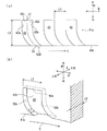
図1に示すように、本実施形態の蒸気タービン(ターボ機械)1は、ケーシング(第一構造体)10と、ケーシング10の内部に回転自在に設けられ、動力を図示しない発電機等の機械に伝達する回転軸30と、ケーシング10に設けられた静翼40と、回転軸30に設けられた動翼50と、軸線CLを中心に回転軸30を回転可能に支持する軸受部70とを備えて構成されている。静翼40及び動翼50は回転軸30の径方向Rに延びるブレードである。
ケーシング10は静止しているのに対し、動翼50は軸線CLを中心に回転する。つまり、ケーシング10と動翼50(後述のシュラウド51を含む)とは互いに相対回転する。
[1. Overall configuration of steam turbine]
As shown in FIG. 1, a steam turbine (turbo machine) 1 according to the present embodiment is provided with a casing (first structure) 10 and a machine such as a generator (not shown) that is rotatably provided inside the
While the
蒸気(流体)Sは、図示しない蒸気供給源と接続された蒸気供給管20を介して、ケーシング10に形成された主流入口21から導入され、蒸気タービン1の下流側に接続された蒸気排出管22から排出される。
Steam (fluid) S is introduced from a
ケーシング10は、内部空間が気密に封止されていると共に、蒸気Sの流路とされている。このケーシング10の内壁面には、回転軸30が挿通されるリング状の仕切板外輪11が強固に固定されている。
軸受部70は、ジャーナル軸受装置71及びスラスト軸受装置72を備えており、回転軸30を回転自在に支持している。
The
The
静翼40は、ケーシング10から内周側に向かって伸び、回転軸30を囲繞するように放射状に多数配置される環状静翼群を構成しており、それぞれ上述した仕切板外輪11に保持されている。
The
これら複数の静翼40からなる環状静翼群は、回転軸30の軸方向(以下、単に軸方向と呼ぶ)Aに間隔を空けて複数形成されており、蒸気Sの圧力エネルギーを速度エネルギーに変換して、下流側に隣接する動翼50に流入させる。
A plurality of
動翼50は、回転軸30の回転軸本体31の外周部に強固に取り付けられ、各環状静翼群の下流側において、放射状に多数配置されて環状動翼群を構成している。
これら環状静翼群と環状動翼群とは、一組一段とされている。このうち、最終段の動翼群では、回転軸30の周方向(以下、単に周方向と呼ぶ)に隣接する動翼50の先端部同士がリング状のシュラウド(第二構造体)51により連結されている。最終段の動翼群のみなならず他の動翼群、さらには静翼群についてもシュラウド51により連結するようにしても良い。
The moving
These annular stator blade groups and annular rotor blade groups are grouped into one stage. Among these, in the last stage moving blade group, the tip portions of the moving
[2.シール構造]
[2−1.シール構造の全体構造]
図2に示すように、仕切板外輪11の軸方向下流側には、仕切板外輪11の内周部から拡径されケーシング10の内周面を底面(以下、ケーシング底面ともいう)13とする円環状の溝(以下、環状溝と呼ぶ)12が形成されている。環状溝12には、シュラウド51が収容され、ケーシング底面13は、シュラウド51と隙間Gdを介して径方向Rに対向している。
[2. Seal structure]
[2-1. Overall structure of seal structure]
As shown in FIG. 2, on the downstream side in the axial direction of the partition plate
蒸気Sのうち大部分の蒸気SMは、動翼50に流入し、そのエネルギーが回転エネルギーに変換され、この結果、回転軸30に回転が付与される。その一方、蒸気Sのうち一部(例えば、約数%)の蒸気(以下、リーク蒸気と呼ぶ)SLは、動翼50に流入せずに環状溝12にリークする。リーク蒸気SLのエネルギーは回転エネルギーに変換されないので、リーク蒸気SLは、蒸気タービン1の効率を低下させるリーク損失を招く。
Most of the steam SM out of the steam S flows into the
そこで、ケーシング10と動翼50との間の隙間Gdには、本発明の一実施形態としてのシール構造(ステップ型のラビリンスシール)2が設けられている。以下、シール構造2について説明する。
シュラウド51は、軸方向Aにおける中央部分が突出してステップ状に形成されたステップ部3を備えている。具体的には、シュラウド51の径方向Rで外周側の面は、ベース面4と、ベース面4よりも径方向Rで外周側に突出するステップ面5が形成されたステップ部3とを有している。
Therefore, a seal structure (step-type labyrinth seal) 2 as an embodiment of the present invention is provided in the gap Gd between the
The
ケーシング底面13には、シュラウド51に向けて径方向Rで内周側にそれぞれ延在する三つのシールフィン6A,6B,6Cが設けられている(図1では省略)。以下、シールフィン6A,6B,6Cを区別しない場合には、シールフィン6と表記する。シールフィン6は、軸線CL(図1参照)を中心とした環状のものであり、図2に示す横断面形状(周方向に垂直な断面の形状)を全周に亘って一定に有する。
The
上流のシールフィン6Aは、ステップ部3よりも上流側のベース面4に向けて突出し、中間のシールフィン6Bは、ステップ部3のステップ面5に向けて突出し、下流側のシールフィン6Cは、ステップ部3よりも下流側のベース面4に向けて突出している。中間のシールフィン6Bは、上流側のシールフィン6A及び下流側のシールフィン6Cよりも径方向Rの長さが短くなるように形成されている。
The
これらシールフィン6は、シュラウド51との間に微小間隙(クリアランス)mを径方向Rに形成している。これら微小間隙mの各寸法は、ケーシング10や動翼50の熱伸び量や動翼50の遠心伸び量等を考慮して、シールフィン6と動翼50とが接触することがない範囲で設定されている。
隙間Gdには、環状溝12,シュラウド51及びシールフィン6によって上流側キャビティ25と、下流側キャビティ26とが形成される。シールフィン6の軸線方向の位置は、これらキャビティ25,26内に漏洩したリーク蒸気SLの流れの挙動に応じて適宜設定される。
These
An
[2−2.シールフィン]
シールフィン6は、シュラウド51のベース面4やステップ面5と対向する先端の構造に大きな特徴がある。この先端の構造について図3〜図5を参照して説明する。
[2-2. Seal fin]
The
図3に示すように、シールフィン6は、ケーシング底面13(図2参照)から径方向Rで内側に向かって延在するフィン本体61と、フィン本体61の内周縁部61aに複数形成された翼形状の凹所62とを備えて構成される。これらの凹所62は、フィン本体61の内周端61bに開口し、周方向に沿って間隔を空けて、フィン本体61の全周に亘って複数設けられている。換言すると、フィン本体61の内周縁部61は、軸方向Aに関する厚み寸法の大きな厚肉部と、前記厚み寸法の小さな薄肉部とが周方向に交互に並んで形成されている。
なお、図3では、凹所62を、幅を持たない曲線により模式的に示している。
As shown in FIG. 3, a plurality of
In FIG. 3, the
凹所62は、図4(a),(b)に示すように、周方向に間隔を空けて対面する湾曲状の側壁62a,62bと、これらの側壁62a,62bの各外周縁を繋ぐ外周壁62cと、側壁62a,62b及び外周壁62cの各下流縁の相互間として規定される底壁62dとに囲まれて形成される。
そして、凹所62は、フィン本体61の内周端(延在方向の先端)61bに近くなるにしたがってシュラウド51の回転方向Cに沿った姿勢となる湾曲形状、且つ、前記内周端61bに近くなるにしたがって横断面(前記凹所62内を流れるリーク蒸気SLの流れに垂直となる断面)が小さくなる絞り形状に形成されている。
As shown in FIGS. 4 (a) and 4 (b), the
The
一般的に、シールフィンに向かって流れてくるリーク蒸気SLは、シールフィンの先端(内周端、以下、フィン先端ともいう)に近づくにつれて加速し、フィン先端で最高速度に達する。本実施形態のシールフィン6では、このような形状の凹所62を設けることにより、フィン先端でのリーク蒸気SLの流れを、凹所62により転向することによってさらに加速して、シールフィン6の上流側の静圧を下げることで、リーク蒸気SLの流量(以下、リーク流量という)FLを減らすようにしている。
凹所62によってリーク蒸気SLの流れを加速できるのは、凹所62が絞り形状であることに加えて、凹所62が湾曲形状なので、この湾曲形状に沿って流れるリーク蒸気SLが、遠心力により凹所62内において湾曲形状外周側に偏って流れるようになって、結果的に絞られるようになるためである。
なお、図4(a)ではフィン本体61の内周端61bの円弧形状を便宜的に直線形状で示している。
In general, the leaked steam SL flowing toward the seal fin accelerates as it approaches the tip of the seal fin (inner peripheral end, hereinafter also referred to as fin tip), and reaches the maximum speed at the fin tip. In the
The reason why the flow of the leak steam SL can be accelerated by the
In FIG. 4A, the arc shape of the inner
ここで、凹所62の主な寸法L1,L2,L3,L4について説明する。
寸法L1は、凹所62を規定する側壁62a,62bの軸方向Aに関する寸法(以下、深さ寸法という)である。
寸法L2は、凹所62を規定する外周壁62cの幅方向(径方向Rに直交する方向)Wに関する寸法(以下、幅寸法という)である。
寸法L3は、凹所62の径方向Rに関する寸法(以下、高さ寸法という)である。凹所62の高さ寸法とは、詳細には、図4(a)に示す正面図(上流側から視た図)において、交点C1と交点C2との径方向Rに関する距離をいい、交点C1は、凹所62を規定する底壁62dの幅方向Wに関する中心線CLWと外周壁62cとの交点であり、交点C2は、中心線CLWとフィン本体61の内周端61bとの交点である。
寸法L4は、周方向に隣接する凹所62の外周端における幅方向Wに関する相互間距離(すなわち凹所62を規定する外周壁62cの幅方向Wに関する相互間距離)である。
Here, the main dimensions L1, L2, L3, and L4 of the
The dimension L1 is a dimension (hereinafter referred to as a depth dimension) in the axial direction A of the
The dimension L2 is a dimension (hereinafter referred to as a width dimension) related to the width direction (direction orthogonal to the radial direction R) W of the outer
The dimension L3 is a dimension related to the radial direction R of the recess 62 (hereinafter referred to as a height dimension). Specifically, the height dimension of the
The dimension L4 is a mutual distance in the width direction W at the outer peripheral end of the
寸法L1,L2,L3,L4の好ましい範囲が、解析により判明しており、それぞれ、フィン本体61の厚肉部(凹所62の形成されていない部分)における軸方向Aに関する寸法(以下、厚さ寸法という)L0を基準寸法として規定される。深さ寸法L1の好ましい範囲は、厚さ寸法L0の0.8倍以下(L1≦0.8×L0)、幅寸法L2の好ましい範囲は、厚さ寸法L0の10倍以下(L2≦10×L0)、高さ寸法L3の好ましい範囲は、厚さ寸法L0の20倍以下(L3≦20×L0)、寸法L4の好ましい範囲は、厚さ寸法L0の100倍以下(L4≦100×L0)である。
Desirable ranges of the dimensions L1, L2, L3, and L4 have been found by analysis, and the dimensions (hereinafter referred to as thicknesses) in the axial direction A in the thick portion of the fin body 61 (the portion where the
これは以下の理由による。
上述したとおり、シールフィン6では、凹所62を設けることにより、フィン先端でのリーク蒸気SLの流れを、凹所62により転向することによって加速して、シールフィン6の上流側の静圧を下げることでリーク流量FLを減らすようにしている。
寸法L1が厚さ寸法L0の0.8倍よりも大きいと(L1>0.8×L0)、凹所62の中に軸方向空間に(軸方向Aに対して)大きな死水域が生じてしまい、凹所62の中でのリーク蒸気SLの流れの転向が十分になされない。一方、寸法L1が厚さ寸法L0の0.8倍以下であると(L1≦0.8×L0)、凹所62の中に大きな死水域が生じず、リーク蒸気SLの流れの転向が凹所62の中で効果的に行われ、リーク蒸気SLの流れ効果的に加速できる結果、フィン上流の静圧を下げることができる。
This is due to the following reason.
As described above, in the
When the dimension L1 is larger than 0.8 times the thickness dimension L0 (L1> 0.8 × L0), a large dead water area is generated in the axial space in the recess 62 (relative to the axial direction A). Therefore, the flow of the leaked steam SL in the
寸法L2が厚さ寸法L0の10倍以下であると(L2≦10×L0)、凹所62の中でのリーク蒸気SLの流れの転向が凹所62の中で効果的に行われ、リーク蒸気SLの流れ効果的に加速できる結果、シールフィン6の上流側の静圧を下げることができる。一方、寸法L2が厚さ寸法L0の10倍を超えると(L2>10×L0)、凹所62によってリーク蒸気SLの流れが十分に転向されない。
When the dimension L2 is 10 times or less than the thickness dimension L0 (L2 ≦ 10 × L0), the diversion of the flow of the leaked steam SL in the
高さ寸法L3が厚さ寸法L0の20倍以下であると(L3≦20×L0)、凹所62の中でリーク蒸気SLの流れが急激に転向するようになるので、このリーク蒸気SLの流れが効果的に加速され、シールフィン6の上流側の静圧を下げることができる。
寸法L4が、厚さ寸法L0の100倍以下(L4≦100×L0)であると、凹所62によって転向されたリーク蒸気SLの流れが、凹所62を通過しない周囲のリーク蒸気SLに作用し、この周囲のリーク蒸気SLの流れも転向するようなる。このため、転向することによって加速するリーク蒸気SLの流量が多くなり、周方向に対して均一に静圧を下げることができる。
When the height dimension L3 is 20 times or less than the thickness dimension L0 (L3 ≦ 20 × L0), the flow of the leak steam SL suddenly turns in the
When the dimension L4 is not more than 100 times the thickness dimension L0 (L4 ≦ 100 × L0), the flow of the leak steam SL turned by the
[3.作用・効果]
本発明の一実施形態としてのシール構造2及びシールフィン6の作用・効果を、図2及び図5を参照して説明する。
図2に示すようにリーク蒸気SLは、シールフィン6の存在により径方向Rに縮流することによって、シールフィン6とシュラウド51との微小隙間mを通過する(リークする)ことが抑制される。その上、本発明の一実施形態としてのシール構造2及びシールフィン6によれば、さらに、縮流してシールフィン6の内周縁部61aまで流れてきたリーク蒸気SLが、図5に示すように、凹所62の形状(周方向に湾曲した形状)に沿って周方向に流れるようになる。したがって、リーク蒸気SLの流れにおける軸方向Aへの速度成分(つまり微小隙間mへ向かう速度成分)が、周方向の速度成分に変換されるので、リーク蒸気SLの微小隙間mを通過しようとする流れが弱まり、微小隙間mを通過するリーク蒸気SLの流量FLを抑制することができる(高いリーク抑制効果が得られる)。
[3. Action / Effect]
The operation and effect of the
As shown in FIG. 2, the leakage steam SL is prevented from passing (leaking) through the minute gap m between the
また、凹所62の湾曲形状が、内周縁部61aに近くなるにしたがって(つまり凹所62内におけるリーク蒸気SLの流通方向下流側になるほど)回転軸30の回転方向Cに沿った姿勢となるので、凹所62から流出したリーク蒸気SLは回転軸30の回転方向Cに向かって流れるようになる。したがって、リーク蒸気SLとシュラウド51との摩擦が抑制され、ひいては摩擦損失によりタービン効率の低下を抑制することができる。
Further, as the curved shape of the
さらに、凹所62は、内周端61bに近くなるにしたがって、横断面(図5に一点鎖線の矢印で示すリーク蒸気SLの流れに垂直な断面)が狭くなる絞り形状とされているので、リーク蒸気SLは、凹所62を通過する過程で加速される結果、その静圧が低下する。これにより、微小隙間mを通過するリーク流量FLを一層効果的に抑制することができる(一層高いリーク抑制効果が得られる)。
Furthermore, the
さらに、凹所62の主要寸法L1,L2,L3,L4を適宜の範囲に設定することで、より高いリーク抑制効果を得ることができる。
Furthermore, by setting the main dimensions L1, L2, L3, and L4 of the
また、このようなリーク抑制効果の高いシールフィン6を使用することで、蒸気タービン1のリーク損失を抑制して高いタービン効率を得ることができる。
Moreover, by using such a
シールフィン6の内周縁部61aの厚み寸法(軸方向Aに関する寸法)が薄いほどシール抑制効果が高くなる。厚み寸法が厚いと、縮流したリーク蒸気SLが下流側で広がってシールフィン6の底面に再付着してしまうためである。シールフィン6に内周縁部61aに凹所62を設けることは、内周縁部61aに薄肉部を設けることであるから、この点でもリーク抑制効果を高めることができる。
As the thickness dimension (dimension with respect to the axial direction A) of the inner
[4.その他]
(1)シールフィン6に設けた凹所62の形状は上記実施形態のものに限定されない。例えば、図3に示すシールフィン6において、凹所62に替えて、図6(a),(b)に示す凹所62A,62Bを使用しても良い。なお、図6(a),(b)ではフィン本体61の内周端61bの円弧形状を便宜的の直線形状で示している。
[4. Others]
(1) The shape of the
図6(a)に示す凹所62Aは、フィン本体61の内周端61bに向かって、回転軸31(図1参照)の回転方向Cで下流側に傾斜して形成され、上記実施形態の凹所62(図4(a),(b)参照)とは異なり、その凹所62Aを画成する両側壁62a′,62b′がストレート形状となっている。
このような構成でも、凹所62Aにより案内されて、リーク蒸気SL1,SL2の流れの軸方向Aに向かう速度成分が、周方向への速度成分に変換されるので、リーク蒸気SLの微小隙間mを通過しようとする軸方向Aへの流れが弱まり、高いリーク抑制効果が得られる。
The
Even in such a configuration, the velocity component directed in the axial direction A of the flow of the leak steams SL1 and SL2 guided by the
また、凹所62Aは、凹所62とは異なり絞り形状ではないが、リーク蒸気SLは静翼40(図1及び図2参照)を通過する際に、動翼50(図2参照)を回転方向Cに回転駆動する方向に旋回力が付与される。このため、リーク蒸気SL1,SL2は、図6(a)中に一点鎖線の矢印で示すように、遠心力により凹所62A内において旋回方向外周側に偏って流れるようになるので、結果的に絞られるようになる。したがって、リーク蒸気SL1,SL2が加速して静圧が低下し、上記実施形態の凹所62と同様に絞りによりリーク抑制効果も得られる。
Unlike the
さらに、凹所62Aは、フィン本体61の内周端61bに近づくほど、回転軸31(図1参照)の回転方向Cで下流側になる傾斜姿勢に形成されているので、凹所62Aから流出したリーク蒸気SL1,SL2の流れは回転方向Cに向かう速度成分を有しているので、シュラウド51(図2参照)との摩擦を抑制することができる。
Furthermore, since the
図6(b)に示す凹所62Bは、凹所62Bを画成する両側壁62a″,62b″が径方向Rに沿った形状とされ、全体的に径方向Rに沿ったストレート形状に形成されている。
このような構成でも、図6(a)に示す凹所62Aと同様に、動翼により旋回力を付与されたリーク蒸気SL1,SL2は、旋回方向外周側に偏って流れるようになるので、結果的に絞られるようになってリーク抑制効果が得られる。
The
Even in such a configuration, the leakage steam SL1 and SL2 to which the turning force is applied by the moving blades flow in an eccentric manner toward the outer peripheral side in the turning direction, similarly to the
また、図6(a),(b)に示す構成においても、凹所62A,62Bを設けることで、シールフィン6の内周縁部61aに薄肉部を設けることができるので、薄肉部によるリーク抑制効果が得られる
6 (a) and 6 (b), by providing the
さらに、動翼により旋回力を付与されたリーク蒸気、すなわち周方向への速度成分を有するリーク蒸気が、周方向に対して交差する側壁62a′, 62a″, 62b′, 62bに衝突することでリーク蒸気の流れを弱体化させるので、この点でも リーク抑制効果が得られる。
Further, the leak steam given the swirl force by the moving blade, that is, the leak steam having the velocity component in the circumferential direction collides with the
なお、凹所62A,62Bを絞り形状としても良いし、凹所62Aを図6(a)とは逆向きの傾斜姿勢(内周端61bに向かって回転方向Cで上流側になる傾斜姿勢)に形成しても良い
Note that the
(2)上記実施形態では、本発明のシール構造を、ケーシング10と動翼50との間のシール構造に適用したが、回転軸本体31と静翼40との間のシール構造に適用することもできる。
(2) In the above embodiment, the seal structure of the present invention is applied to the seal structure between the
(3)上記実施形態では、シュラウド51にステップ型を使用したが、シュラウド51を、ステップのない直通型としても良い。
(3) Although the step type is used for the
(4)上記実施形態では、シールフィン6A,6B,6Cの全てについて凹所62を設けたが、シールフィン6A,6B,6Cの少なくとも1つに凹所62を設ければ良い。
また、シールフィン6A,6B,6C毎に異なる形状の凹所を設けても良い。例えば、シールフィン6Aに凹所62を設け、シールフィン6Bに凹所62Aを設け、シールフィン6Cに凹所62Bを設けても良い。
或いは、単一のシールフィン6に異なる形状の凹所62,62A,62Bを混在して設けても良い。
(4) In the above embodiment, the
Moreover, you may provide the recess of a different shape for every
Alternatively, the
(5)上記実施形態では、蒸気タービンに本発明を適用した例を説明したが、本発明は、ガスタービンやターボ圧縮機など、蒸気タービン以外のターボ機械のシールにも適用することができ、さらには、相対的に回転する二つの構造体の間のシールであれば、ターボ機械以外のもの(例えばロータリージョイント)のシールにも適用できるものである。 (5) In the above embodiment, an example in which the present invention is applied to a steam turbine has been described, but the present invention can also be applied to a seal of a turbo machine other than a steam turbine, such as a gas turbine or a turbo compressor, Furthermore, as long as the seal is between two relatively rotating structures, the seal can be applied to a seal other than a turbo machine (for example, a rotary joint).
1 蒸気タービン(ターボ機械)
2 シール構造
3 ステップ部
4 ベース面
5 ステップ面
6,6A,6B,6C シールフィン
10 ケーシング(第一構造体)
12 環状溝
13 底面
25,26 キャビティ
30 回転軸
31 回転軸本体
40 静翼
50 動翼
51 シュラウド(第二構造体)
61 フィン本体
61a フィン本体61の内周縁部
61b フィン本体61の内周端
62,62A,62B 凹所
62a,62a′,62b,62b′ 凹所を画成する側壁
62c 凹所62を画成する外周壁
62d 凹所62を画成する底壁
A 軸方向
C 回転軸30の回転方向
CL 軸線
Gd 隙間
L0 フィン本体61の厚さ寸法
L1 凹所62の深さ寸法
L2 凹所62の幅寸法
L3 凹所62の高さ寸法
L4 隣接する凹所62の相互間距離
m 微小間隙(クリアランス)
R 径方向
S 蒸気(流体)
SL リーク蒸気
T 厚さ方向
W 幅方向
1 Steam turbine (turbo machine)
2
6,6A, 6B,
12
61 Fin
R radial direction S steam (fluid)
SL Leakage steam T Thickness direction W Width direction
Claims (8)
前記第一構造体に、前記第二構造体に向かって延在して、その延在方向の先端面と前記第二構造体との間にクリアランスをあけて設けられたシールフィンを備え、
前記シールフィンにおける前記流体の流通方向で上流側に向く前面には、その前記延在方向の先端に開口する凹所が、周方向に沿って複数並設された
ことを特徴とするシール構造。 A seal structure that prevents fluid from leaking from the gap between the stationary first structure and the second structure rotating about the axis with a gap between each other in the radial direction,
The first structure includes a seal fin that extends toward the second structure and is provided with a clearance between the distal end surface in the extending direction and the second structure,
The seal structure according to claim 1, wherein a plurality of recesses opened at the front end in the extending direction are arranged in parallel along the circumferential direction on a front surface of the seal fin facing upstream in the fluid flow direction.
ことを特徴とする、請求項1記載のシール構造。 The seal structure according to claim 1, wherein the recess is formed in a curved shape having a posture along the circumferential direction as it approaches the tip.
ことを特徴とする、請求項2記載のシール構造。 The seal structure according to claim 2, wherein the curved shape is a shape that takes a posture along a rotation direction of the second structure as it approaches the tip.
ことを特徴とする、請求項1記載のシール構造。 The seal structure according to claim 1, wherein the recess is formed to be inclined with respect to the radial direction.
ことを特徴とする、請求項4記載のシール構造。 The seal structure according to claim 4, wherein the recess is inclined toward the distal end of the second structure in the rotation direction.
ことを特徴とする、請求項1〜5の何れか一項に記載のシール構造。 6. The recess according to claim 1, wherein a cross-section perpendicular to the flow direction of the fluid flowing in the recess is formed in a throttle shape that becomes smaller as it approaches the tip. The seal structure according to one item.
前記凹所における前記軸線に沿った深さ寸法が、前記基準寸法の0.8倍以下に設定され、
前記凹所の前記径方向外側の端部における前記径方向と直交する幅方向の寸法が、前記基準寸法の10倍以下に設定され、
前記凹所の前記径方向の高さ寸法が、前記基準寸法の20倍以下に設定され、
前記周方向に隣接する前記凹所の相互間距離が、前記基準寸法の100倍以下に設定された
ことを特徴とする、請求項1〜6の何れか一項に記載のシール構造。 The thickness dimension along the axis of the seal fin at a location where the recess is not formed is a reference dimension,
The depth dimension along the axis in the recess is set to 0.8 times or less of the reference dimension,
The dimension in the width direction orthogonal to the radial direction at the radially outer end of the recess is set to 10 times or less of the reference dimension,
The radial height dimension of the recess is set to be 20 times or less of the reference dimension;
The seal structure according to any one of claims 1 to 6, wherein a distance between the recesses adjacent to each other in the circumferential direction is set to 100 times or less of the reference dimension.
Priority Applications (6)
| Application Number | Priority Date | Filing Date | Title |
|---|---|---|---|
| JP2015240489A JP6167158B2 (en) | 2015-12-09 | 2015-12-09 | Seal structure and turbomachine |
| KR1020187015326A KR102050186B1 (en) | 2015-12-09 | 2016-11-28 | Seal pin, seal structure and turbo machine |
| DE112016005649.4T DE112016005649T5 (en) | 2015-12-09 | 2016-11-28 | Sealing rib, sealing structure and turbomachinery |
| CN201680070949.6A CN108368744B (en) | 2015-12-09 | 2016-11-28 | Sealing fin, sealing structure and turbine machine |
| PCT/JP2016/085177 WO2017098944A1 (en) | 2015-12-09 | 2016-11-28 | Seal fin, seal structure, and turbomachine |
| US15/780,781 US10982719B2 (en) | 2015-12-09 | 2016-11-28 | Seal fin, seal structure, and turbo machine |
Applications Claiming Priority (1)
| Application Number | Priority Date | Filing Date | Title |
|---|---|---|---|
| JP2015240489A JP6167158B2 (en) | 2015-12-09 | 2015-12-09 | Seal structure and turbomachine |
Publications (2)
| Publication Number | Publication Date |
|---|---|
| JP2017106544A true JP2017106544A (en) | 2017-06-15 |
| JP6167158B2 JP6167158B2 (en) | 2017-07-19 |
Family
ID=59013099
Family Applications (1)
| Application Number | Title | Priority Date | Filing Date |
|---|---|---|---|
| JP2015240489A Active JP6167158B2 (en) | 2015-12-09 | 2015-12-09 | Seal structure and turbomachine |
Country Status (6)
| Country | Link |
|---|---|
| US (1) | US10982719B2 (en) |
| JP (1) | JP6167158B2 (en) |
| KR (1) | KR102050186B1 (en) |
| CN (1) | CN108368744B (en) |
| DE (1) | DE112016005649T5 (en) |
| WO (1) | WO2017098944A1 (en) |
Families Citing this family (3)
| Publication number | Priority date | Publication date | Assignee | Title |
|---|---|---|---|---|
| US10690251B2 (en) * | 2016-09-23 | 2020-06-23 | General Electric Company | Labyrinth seal system and an associated method thereof |
| FR3073595B1 (en) | 2017-11-15 | 2020-02-07 | Safran Helicopter Engines | LABYRINTH JOINT COMPRISING A STICK WITH A DEFLECTOR |
| CN114526161B (en) * | 2022-04-22 | 2022-07-08 | 成都中科翼能科技有限公司 | Gas turbine's intermediary machine casket and reinforcement structure thereof |
Citations (6)
| Publication number | Priority date | Publication date | Assignee | Title |
|---|---|---|---|---|
| JPH09324655A (en) * | 1996-06-07 | 1997-12-16 | Hitachi Ltd | Gas expansion turbine |
| JP2001032948A (en) * | 1999-07-21 | 2001-02-06 | Hitachi Ltd | Rotating fluid machine |
| JP2011202601A (en) * | 2010-03-26 | 2011-10-13 | Hitachi Ltd | Rotor oscillation preventing structure and steam turbine using the same |
| JP2011208602A (en) * | 2010-03-30 | 2011-10-20 | Mitsubishi Heavy Ind Ltd | Turbine |
| JP2015108301A (en) * | 2013-12-03 | 2015-06-11 | 三菱重工業株式会社 | Seal structure and rotary machine |
| JP2015140916A (en) * | 2014-01-30 | 2015-08-03 | 三菱重工業株式会社 | Seal structure and rotary machine |
Family Cites Families (18)
| Publication number | Priority date | Publication date | Assignee | Title |
|---|---|---|---|---|
| US1756958A (en) * | 1928-10-03 | 1930-05-06 | Westinghouse Electric & Mfg Co | Elastic-fluid turbine |
| US3251601A (en) * | 1963-03-20 | 1966-05-17 | Gen Motors Corp | Labyrinth seal |
| US4351532A (en) * | 1975-10-01 | 1982-09-28 | United Technologies Corporation | Labyrinth seal |
| JPS5340267A (en) | 1976-09-27 | 1978-04-12 | Toshiba Corp | Electron gun assembling body |
| US5029876A (en) | 1988-12-14 | 1991-07-09 | General Electric Company | Labyrinth seal system |
| GB2251040B (en) * | 1990-12-22 | 1994-06-22 | Rolls Royce Plc | Seal arrangement |
| US5298016A (en) * | 1992-03-02 | 1994-03-29 | Advanced Haemotechnologies | Apparatus for separating plasma and other wastes from blood |
| US6139018A (en) * | 1998-03-25 | 2000-10-31 | General Electric Co. | Positive pressure-actuated brush seal |
| EP1212557A4 (en) * | 1999-07-15 | 2006-05-10 | Christopher Frederick Bayne | Shaft seals for sealing pulverulent solids |
| JP4598583B2 (en) | 2005-03-31 | 2010-12-15 | 株式会社日立製作所 | Steam turbine seal equipment |
| US7445213B1 (en) * | 2006-06-14 | 2008-11-04 | Florida Turbine Technologies, Inc. | Stepped labyrinth seal |
| DE102007004743A1 (en) | 2007-01-31 | 2008-08-07 | Mtu Aero Engines Gmbh | Sealant arrangement for turbomachine i.e. gas turbine, has sealing bodies including projections that are distributed over circumference, where projections extend into flow chamber, and rotor-sided sealing body formed as sealing fin |
| JP2008196522A (en) | 2007-02-08 | 2008-08-28 | Toshiba Corp | Sealing device |
| US20090072487A1 (en) | 2007-09-18 | 2009-03-19 | Honeywell International, Inc. | Notched tooth labyrinth seals and methods of manufacture |
| JP5709447B2 (en) | 2010-09-28 | 2015-04-30 | 三菱日立パワーシステムズ株式会社 | Turbine |
| US8591181B2 (en) * | 2010-10-18 | 2013-11-26 | General Electric Company | Turbomachine seal assembly |
| GB2492546A (en) | 2011-07-04 | 2013-01-09 | Alstom Technology Ltd | A labyrinth seal for an axial fluid flow turbomachine |
| GB201305702D0 (en) | 2013-03-28 | 2013-05-15 | Rolls Royce Plc | Seal segment |
-
2015
- 2015-12-09 JP JP2015240489A patent/JP6167158B2/en active Active
-
2016
- 2016-11-28 US US15/780,781 patent/US10982719B2/en active Active
- 2016-11-28 WO PCT/JP2016/085177 patent/WO2017098944A1/en active Application Filing
- 2016-11-28 CN CN201680070949.6A patent/CN108368744B/en active Active
- 2016-11-28 DE DE112016005649.4T patent/DE112016005649T5/en active Pending
- 2016-11-28 KR KR1020187015326A patent/KR102050186B1/en active IP Right Grant
Patent Citations (6)
| Publication number | Priority date | Publication date | Assignee | Title |
|---|---|---|---|---|
| JPH09324655A (en) * | 1996-06-07 | 1997-12-16 | Hitachi Ltd | Gas expansion turbine |
| JP2001032948A (en) * | 1999-07-21 | 2001-02-06 | Hitachi Ltd | Rotating fluid machine |
| JP2011202601A (en) * | 2010-03-26 | 2011-10-13 | Hitachi Ltd | Rotor oscillation preventing structure and steam turbine using the same |
| JP2011208602A (en) * | 2010-03-30 | 2011-10-20 | Mitsubishi Heavy Ind Ltd | Turbine |
| JP2015108301A (en) * | 2013-12-03 | 2015-06-11 | 三菱重工業株式会社 | Seal structure and rotary machine |
| JP2015140916A (en) * | 2014-01-30 | 2015-08-03 | 三菱重工業株式会社 | Seal structure and rotary machine |
Also Published As
| Publication number | Publication date |
|---|---|
| JP6167158B2 (en) | 2017-07-19 |
| US20180372158A1 (en) | 2018-12-27 |
| CN108368744A (en) | 2018-08-03 |
| US10982719B2 (en) | 2021-04-20 |
| KR20180078283A (en) | 2018-07-09 |
| WO2017098944A1 (en) | 2017-06-15 |
| DE112016005649T5 (en) | 2018-08-30 |
| KR102050186B1 (en) | 2019-11-28 |
| CN108368744B (en) | 2020-05-08 |
Similar Documents
| Publication | Publication Date | Title |
|---|---|---|
| JP6344735B2 (en) | Seal structure and rotating machine | |
| JP6209200B2 (en) | Step seal, seal structure, turbomachine, and step seal manufacturing method | |
| JP5972374B2 (en) | Axial fluid machine | |
| KR20140052864A (en) | Axial flow turbine | |
| KR102031510B1 (en) | Seal structure and turbine | |
| KR20130114165A (en) | Turbine | |
| JP2015108301A (en) | Seal structure and rotary machine | |
| US11187097B2 (en) | Rotary machine | |
| JP2011137458A (en) | System and apparatus relating to compressor operation in turbo engine | |
| JP6167158B2 (en) | Seal structure and turbomachine | |
| JP6726986B2 (en) | Sealing device, rotary machine | |
| WO2017098959A1 (en) | Seal fin, seal structure, turbomachine, and method for producing seal fin | |
| JP6712873B2 (en) | Seal structure and turbo machine | |
| US11136897B2 (en) | Seal device and turbomachine | |
| JP2014238066A (en) | Rotary machine | |
| JP2018040282A (en) | Axial flow turbine and diaphragm outer ring thereof | |
| JP2014152696A (en) | Labyrinth seal device, and turbomachine using the same | |
| JP2017160861A (en) | Turbo machine | |
| JP2014199059A (en) | End wall member and gas turbine | |
| JP6662661B2 (en) | Seal structure and turbo machinery | |
| JP5909081B2 (en) | Turbomachine sealing assembly and method for assembling the same | |
| JP2013113222A (en) | Steam turbine | |
| JP2010275957A (en) | Turbine | |
| JP2010275953A (en) | End wall member and gas turbine | |
| JP5852190B2 (en) | End wall member and gas turbine |
Legal Events
| Date | Code | Title | Description |
|---|---|---|---|
| TRDD | Decision of grant or rejection written | ||
| A01 | Written decision to grant a patent or to grant a registration (utility model) |
Free format text: JAPANESE INTERMEDIATE CODE: A01 Effective date: 20170613 |
|
| A61 | First payment of annual fees (during grant procedure) |
Free format text: JAPANESE INTERMEDIATE CODE: A61 Effective date: 20170626 |
|
| R150 | Certificate of patent or registration of utility model |
Ref document number: 6167158 Country of ref document: JP Free format text: JAPANESE INTERMEDIATE CODE: R150 |
|
| S533 | Written request for registration of change of name |
Free format text: JAPANESE INTERMEDIATE CODE: R313533 |
|
| R350 | Written notification of registration of transfer |
Free format text: JAPANESE INTERMEDIATE CODE: R350 |