JP2017100558A - Seat structure for vehicle - Google Patents
Seat structure for vehicle Download PDFInfo
- Publication number
- JP2017100558A JP2017100558A JP2015235114A JP2015235114A JP2017100558A JP 2017100558 A JP2017100558 A JP 2017100558A JP 2015235114 A JP2015235114 A JP 2015235114A JP 2015235114 A JP2015235114 A JP 2015235114A JP 2017100558 A JP2017100558 A JP 2017100558A
- Authority
- JP
- Japan
- Prior art keywords
- air
- seat cushion
- vehicle
- seat
- air conditioning
- Prior art date
- Legal status (The legal status is an assumption and is not a legal conclusion. Google has not performed a legal analysis and makes no representation as to the accuracy of the status listed.)
- Granted
Links
- 238000004378 air conditioning Methods 0.000 claims abstract description 49
- 238000007664 blowing Methods 0.000 abstract description 9
- 230000001143 conditioned effect Effects 0.000 description 29
- 230000035699 permeability Effects 0.000 description 2
- 210000001217 buttock Anatomy 0.000 description 1
- 238000010411 cooking Methods 0.000 description 1
Images

Abstract
Description
本発明は、車両用シート構造に関する。 The present invention relates to a vehicle seat structure.
従来、車両用シート構造は、例えば、車両の前部座席のシートクッションの内部に空調用の配管を設け、その配管の吹き出し口から空調空気を吹き出すことによって、シート表面材を介してシートクッションに着座した乗員に空調空気を吹き付ける構成が知られている(例えば、特許文献1)。 Conventionally, in a vehicle seat structure, for example, an air conditioning pipe is provided inside a seat cushion of a front seat of a vehicle, and air-conditioned air is blown out from a blowout port of the pipe, whereby the seat cushion is formed via a seat surface material. A configuration in which conditioned air is blown to a seated passenger is known (for example, Patent Document 1).
また、シートクッションの前面(車両前方側の面)側から車両前方に空調空気を吹き出す吹き出し口が設けられており、乗員の足元を所定の温度にする機能が備えられている。 In addition, a blow-out port for blowing conditioned air from the front surface (front surface of the vehicle) side of the seat cushion to the front of the vehicle is provided, and a function of bringing a passenger's feet to a predetermined temperature is provided.
ところが、シートクッションの前面側に吹き出し口を設けた場合、シートクッションから前方(車両前方)に吹き出された空調空気の流れによって、シートクッションの下方に滞留していた空気がシートクッションの前方に引き出される(流入する)。この結果、前部座席の乗員の足元が目標温度に空調されるまでの時間、すなわち空調効率について改善の余地があった。 However, when the air outlet is provided on the front side of the seat cushion, the air staying below the seat cushion is drawn out to the front of the seat cushion by the flow of conditioned air blown forward from the seat cushion (front of the vehicle). (Inflow). As a result, there is room for improvement in the time until the feet of the passengers in the front seat are air-conditioned to the target temperature, that is, the air-conditioning efficiency.
本発明は上記事実を考慮し、前部座席の乗員の足元に対する空調効率を向上させた車両用シート構造を提供することを目的とする。 In consideration of the above-described facts, an object of the present invention is to provide a vehicle seat structure with improved air-conditioning efficiency with respect to the feet of a passenger in a front seat.
請求項1記載の発明は、乗員を支持するシートクッションと、空調空気発生源と連通し、前記シートクッションの内部でシートクッションの前部先端側と下部先端側まで延在して設けられた空調用ダクトと、前記空調用ダクトの前記前部先端側に設けられ、前記シートクッションの前面から当該シートクッションの車両前方に向けて開口された前部吹き出し口と、前記空調用ダクトの前記下部先端側に設けられ、前記シートクッションの下面から当該シートクッションの車両下方に向けて開口された下部吹き出し口と、を備える。 According to a first aspect of the present invention, an air conditioner is provided that communicates with a seat cushion that supports an occupant and an air-conditioning air generation source, and extends to the front end side and the lower end side of the seat cushion within the seat cushion. Duct, a front outlet provided at the front end side of the air conditioning duct and opened from the front surface of the seat cushion toward the front of the vehicle of the seat cushion, and the lower end of the air conditioning duct A lower outlet that is provided on a side of the seat cushion and opens from the lower surface of the seat cushion toward the vehicle lower side of the seat cushion.
この構成によれば、空調空気発生源からシートクッションの内部に設けられた空調用ダクトに空調空気が供給され、シートクッションの内部で空調用ダクトの前部先端側で開口した前部吹き出し口からシートクッションの車両前方に空調空気が吹き出される。これによって、シートクッションに着座した乗員の足元に空調空気が吹き出されて、乗員の足元が所定温度に空調される。また、シートクッションの内部で空調用ダクトの下部先端側で開口した下部吹き出し口から車両下方に空調空気が吹き出される。すなわち、シートクッションの車両下方に空調空気が吹き出されることによって、いわゆるエアカーテンがシートクッションの下方に形成される。この結果、前部吹き出し口からの空調空気の吹き出しに伴って、シートクッション下方に滞留していた空気がシートクッションの前方に引き出される(流入する)ことが防止または抑制される。したがって、シートクッションに着座した乗員の足元を所定温度に空調するまでの時間が短縮される。 According to this configuration, the conditioned air is supplied from the conditioned air generation source to the air conditioning duct provided inside the seat cushion, and the front air outlet that opens at the front end side of the air conditioning duct inside the seat cushion is provided. Air-conditioned air is blown out in front of the seat cushion. As a result, the conditioned air is blown out to the feet of the passenger seated on the seat cushion, and the feet of the passenger are air-conditioned to a predetermined temperature. In addition, air-conditioned air is blown out from the lower air outlet opening at the lower end of the air-conditioning duct inside the seat cushion to the lower side of the vehicle. That is, when the conditioned air is blown out below the seat cushion in the vehicle, a so-called air curtain is formed below the seat cushion. As a result, the air staying below the seat cushion is prevented or suppressed from being drawn (inflowed) forward of the seat cushion with the blowing of conditioned air from the front outlet. Therefore, the time until the feet of the passenger sitting on the seat cushion are air-conditioned to a predetermined temperature is shortened.
請求項1記載の発明の車両用シート構造は、上記構成としたので、前部座席の乗員の足元の空調効率を向上させることができる。 Since the vehicle seat structure according to the first aspect of the present invention has the above-described configuration, it is possible to improve the air conditioning efficiency at the feet of the passengers in the front seat.
本発明の一実施形態に係る車両用シート構造について図1及び図2を参照して説明する。なお、図面においては、本発明の内容に関連しない部品の記載は省略している。また、図上、矢印FRは車両前方、矢印UPは車両上方を示している。 A vehicle seat structure according to an embodiment of the present invention will be described with reference to FIGS. 1 and 2. In the drawings, the description of parts not related to the contents of the present invention is omitted. In the figure, the arrow FR indicates the front of the vehicle, and the arrow UP indicates the upper side of the vehicle.
(構成)
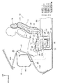
図1に示すように、車両用シート構造は、前部座席用のシート10であり、乗員が着座するシートクッション12と、乗員の背面を支持するシートバック14と、乗員の頭部を支持するヘッドレスト16とを備えている。
(Constitution)
As shown in FIG. 1, the vehicle seat structure is a
シートクッション12は、クッションパッド18とその表面を覆う表皮20とから形成されている。シートクッション12の内部には、車両前後方向に延在する空調用ダクト22が形成されており、シートクッション12の下面に開口した導入口24を介して後述するエアコンユニット44から空調空気が導入される構成とされている。
The
また、空調用ダクト22は、シートクッション12の内部において導入口24から分岐して車両上方の上面12A側、車両前方の前面12B側、車両下方の下面12C側まで延在している。空調用ダクト22は、上面12A側で車両上方に開口された上部吹き出し口26と、前面12B側で車両前方に開口された前部吹き出し口28と、下面12C側で車両下方に開口された下部吹き出し口30とが形成されている。なお、下部炊き出し口30は、下面12Cにおいて車両前方(先端)側に開口されている。
したがって、空調用ダクト22に導入口24から空調空気が導入されると、上部吹き出し口26、前部吹き出し口28、下部吹き出し口30から通気性を有する表皮20を介してシートクッション12の上面12A、前面12B、下面12Cから空調空気がそれぞれ吹き出される構成である。
The
Therefore, when the conditioned air is introduced into the
なお、本実施形態では、図1に示すように、上部吹き出し口26、前部吹き出し口28、下部吹き出し口30は、クッションパッド18の表面(表皮20の裏側)で開口しているが、通気性を有するクッションパッド18の内部で開口していても良い。すなわち、シートクッション12の上面12A、前面12B、下面12Cから空調空気を吹き出し可能であれば良い。
In this embodiment, as shown in FIG. 1, the
シートバック14も、クッションパッド32とその表面を覆う表皮34とから形成されている。シートバック14の内部には、車両上下方向に延在し空調用ダクト22と連通された空調用ダクト36が形成されており、シートクッション12の導入口24を介して後述する空調装置40から空調空気が導入される構成とされている。空調用ダクト36は、シートバック14の内部で車両前方の前面14A側まで延在されており、前面14A側に車両前方に開口された前部吹き出し口38を備えている。したがって、空調用ダクト36に空調空気が導入されることにより、前部吹き出し口38から通気性を有する表皮34を介してシートバックの前面14Aから空調空気が吹き出される構成である。
The
次に、シート10の空調用ダクト22、36に空調空気を供給する空調装置40について説明する。空調装置40は、インスツルメントパネル(以下、「インパネ」という)42の車両前方側に配置されたエアコンユニット44を有する。エアコンユニット44は、インパネ42の上面42Aに設けられた吹き出し口46と、インパネ42の下面42Bに設けられた吹き出し口48とを備えており、それぞれシート10に着座した乗員の顔と足元に空調空気を吹き付けるものである。
Next, an
さらに、空調装置40は、エアコンユニット44からトンネル部50の側方を介してシート10まで到達した後、シート10の下方を車両前方から車両後方まで延在するリヤフットダクト52を備えている。リヤフットダクト52は、車両後方側端部の吹き出し口54から後部座席の乗員の足元に向かって空調空気を吹き出し可能に構成されている。
Furthermore, the
リヤフットダクト52は、シートクッション12の車両下方において分岐した導入管56によってシートクッション12の導入口24に連通されている。なお、導入管56には、ブロア58が配設されており、ブロア58の駆動によってシートクッション12及びシートバック14の内部に設けられた空調用ダクト22、36に空調空気が導入される構成である。なお、導入管56の上下部分は蛇腹形状とされた蛇腹部60とされており、シート10の上下方向の調整に対応可能とされている。また、図示省略されているが、導入管56の前後方向部分も同様に蛇腹形状とされており、シート10の前後方向の位置調整に対応可能とされている。
The
(作用)
このように構成された車両シート構造の作用について、図1、図2を参照して説明する。なお、図2は、作用(空調空気を流れ)を説明するために、構成の一部を図示省略している。
(Action)
The operation of the vehicle seat structure configured as described above will be described with reference to FIGS. 1 and 2. In FIG. 2, a part of the configuration is not shown in order to explain the action (flow of conditioned air).
先ず、図1に示すように、エアコンユニット44が駆動されると、エアコンユニット44からリヤフットダクト52に空調空気が供給される。この際、ブロア58が駆動されることにより、リヤフットダクト52から導入管56を介して、導入口24からシートクッション12の内部の空調用ダクト22に空調空気が供給される。また、シートクッション12の空調用ダクト22からシートバック14の空調用ダクト36に空調空気が供給される。
First, as shown in FIG. 1, when the
空調用ダクト22内に供給された空調空気は、シートクッション12の上面12Aに設けられた上部吹き出し口26及びシートバック14の前面14Aに設けられた前部吹き出し口38からシート10に着座した乗員の臀部及び背中に吹き付けられる(図2、矢印A、B参照)。
The conditioned air supplied into the
また、シートクッション12の前面12Bに設けられた前部吹き出し口28から車両前方(乗員の足元)に向かって空調空気が吹き出される(図2、矢印C参照)。
In addition, conditioned air is blown out from the front blowing
このようにシート10の上部吹き出し口26、前部吹き出し口28、38から空調空気が乗員に直接吹き付けられることによって、乗員の体感温度を空調の設定温度まで素早く向上させることが可能となる。
As described above, the conditioned air is directly blown to the occupant from the
また、上部吹き出し口26、前部吹き出し口28、38から空調空気を吹き出すと同時に、シートクッション12の下面12Cに設けられた下部吹き出し口30から車両下方に空調空気が吹き出される(図2、矢印D参照)。吹き出し口30から車両下方に吹き出される空調空気によってシートクッション12の前端側下方に、いわゆるエアカーテンが形成される。
In addition, air-conditioned air is blown out from the lower blow-out
この結果、シートクッション12の前面12Bに設けられた前部吹き出し口28から車両前方に空調空気を吹き出した際(図2、矢印C参照)、シートクッション12の車両下方に滞留する空気がこの空調空気の流れによって乗員の足元に引き出される(流入する)こと(図2、破線矢印E参照)が防止又は抑制される。したがって、前部座席に着座した乗員の足元に対する空調効率を向上させることができる。
As a result, when the conditioned air is blown forward of the vehicle from the
特に、乗員の体(脹脛)がシートクッション12の前面12Bから離間しているため、シートクッション12からの空調空気による空調効率が体の他の部位(臀部及び背中)に対する空調効率と比較して相対的に低い乗員の足元の空調効率を向上させることができる。
In particular, since the occupant's body (burnt) is separated from the
また、インパネ42の下面42Bの吹き出し口48から乗員の足元へ車両下方に吹き出される空調空気(図2、矢印F参照)は、後部座席側の空調が不要な場合にも、シートクッション12の下方を介して後部座席側に流れていくおそれがある。しかしながら、吹き出し口30からシートクッション12の車両下方に空調空気を噴出してエアカーテンを形成している(図2、矢印D参照)ので、吹き出し口48から吹き出された空調空気がシートクッション12の下方から後部座席の乗員の足元に流出すること(図2、破線矢印G参照)が防止又は抑制される。この結果、前部座席の乗員の足元の空調効率がさらに向上する。
In addition, the conditioned air (see arrow F in FIG. 2) blown downward from the
なお、本実施形態では、下部吹き出し口30を開閉する機構を設けていないが、必要なときだけ空調空気を車両下方に吹き出してエアカーテンを形成可能なように下部吹き出し口30に開閉機構を設けても良い。
In this embodiment, a mechanism for opening and closing the
また、本実施形態では、シートクッション12の下面12Cの車両前方側に下部吹き出し口30を設けたが、例えば、シートクッションの前面12Bの下方に開閉自在な機械的なシャッターを設けて、シートクッション12の下部とシート10に着座した乗員の足元を物理的に遮断する構成も考えられる。
In the present embodiment, the
10 車両用シート
12 シートクッション
22 空調用ダクト
28 前部吹き出し口
30 下部吹き出し口
44 エアコンユニット(空調空気発生源)
10
Claims (1)
空調空気発生源と連通し、前記シートクッションの内部でシートクッションの前部先端側と下部先端側まで延在して設けられた空調用ダクトと、
前記空調用ダクトの前記前部先端側に設けられ、前記シートクッションの前面から当該シートクッションの車両前方に向けて開口された前部吹き出し口と、
前記空調用ダクトの前記下部先端側に設けられ、前記シートクッションの下面から当該シートクッションの車両下方に向けて開口された下部吹き出し口と、
を備える車両用シート構造。 A seat cushion that supports the occupant;
An air conditioning duct that communicates with an air-conditioning air generation source and extends to the front end side and the lower end side of the seat cushion inside the seat cushion;
A front outlet that is provided on the front end side of the air conditioning duct and is opened from the front surface of the seat cushion toward the front of the vehicle of the seat cushion;
A lower outlet that is provided on the lower tip side of the air conditioning duct and is opened from the lower surface of the seat cushion toward the vehicle lower side of the seat cushion;
A vehicle seat structure comprising:
Priority Applications (1)
| Application Number | Priority Date | Filing Date | Title |
|---|---|---|---|
| JP2015235114A JP6460964B2 (en) | 2015-12-01 | 2015-12-01 | Vehicle seat structure |
Applications Claiming Priority (1)
| Application Number | Priority Date | Filing Date | Title |
|---|---|---|---|
| JP2015235114A JP6460964B2 (en) | 2015-12-01 | 2015-12-01 | Vehicle seat structure |
Publications (2)
| Publication Number | Publication Date |
|---|---|
| JP2017100558A true JP2017100558A (en) | 2017-06-08 |
| JP6460964B2 JP6460964B2 (en) | 2019-01-30 |
Family
ID=59017672
Family Applications (1)
| Application Number | Title | Priority Date | Filing Date |
|---|---|---|---|
| JP2015235114A Expired - Fee Related JP6460964B2 (en) | 2015-12-01 | 2015-12-01 | Vehicle seat structure |
Country Status (1)
| Country | Link |
|---|---|
| JP (1) | JP6460964B2 (en) |
Cited By (1)
| Publication number | Priority date | Publication date | Assignee | Title |
|---|---|---|---|---|
| CN111791672A (en) * | 2020-08-22 | 2020-10-20 | 广州雷易科技有限公司 | Automobile heating equipment |
Citations (4)
| Publication number | Priority date | Publication date | Assignee | Title |
|---|---|---|---|---|
| JPS5635406U (en) * | 1979-08-28 | 1981-04-06 | ||
| JPH0663416A (en) * | 1991-07-09 | 1994-03-08 | Usui Internatl Ind Co Ltd | Exhaust gas cleaning device |
| JP2003285629A (en) * | 2002-03-28 | 2003-10-07 | Denso Corp | Vehicular seat air conditioner |
| JP2004166812A (en) * | 2002-11-18 | 2004-06-17 | Kanto Auto Works Ltd | Seat |
-
2015
- 2015-12-01 JP JP2015235114A patent/JP6460964B2/en not_active Expired - Fee Related
Patent Citations (4)
| Publication number | Priority date | Publication date | Assignee | Title |
|---|---|---|---|---|
| JPS5635406U (en) * | 1979-08-28 | 1981-04-06 | ||
| JPH0663416A (en) * | 1991-07-09 | 1994-03-08 | Usui Internatl Ind Co Ltd | Exhaust gas cleaning device |
| JP2003285629A (en) * | 2002-03-28 | 2003-10-07 | Denso Corp | Vehicular seat air conditioner |
| JP2004166812A (en) * | 2002-11-18 | 2004-06-17 | Kanto Auto Works Ltd | Seat |
Cited By (1)
| Publication number | Priority date | Publication date | Assignee | Title |
|---|---|---|---|---|
| CN111791672A (en) * | 2020-08-22 | 2020-10-20 | 广州雷易科技有限公司 | Automobile heating equipment |
Also Published As
| Publication number | Publication date |
|---|---|
| JP6460964B2 (en) | 2019-01-30 |
Similar Documents
| Publication | Publication Date | Title |
|---|---|---|
| JP5381834B2 (en) | Vehicle seat air conditioner | |
| JP2007517720A (en) | Vehicle seat | |
| JP2014141131A (en) | Vehicle air conditioner | |
| JP4758782B2 (en) | Air conditioner for vehicles | |
| JP2016168944A (en) | Vehicular seat structure, main seat and auxiliary seat | |
| JP2014180985A (en) | Vehicle air conditioning system | |
| JP6460964B2 (en) | Vehicle seat structure | |
| JP6434394B2 (en) | Vehicle register device | |
| JP2015104980A (en) | Vehicular air-conditioning system | |
| JP6627976B2 (en) | Vehicle air conditioner | |
| JP5423791B2 (en) | Duct in vehicle | |
| JP4935515B2 (en) | Air conditioner for vehicles | |
| JP2011063050A (en) | Seat air conditioner | |
| KR101501077B1 (en) | Device for seat lower ventilation of vehicle | |
| JP2008168776A (en) | Vehicular seat air-conditioner | |
| JP5176588B2 (en) | Sheet blower | |
| JP2014196026A (en) | Vehicle air conditioning system | |
| JP2017210190A (en) | Vehicle seat | |
| JP6555420B2 (en) | Sheet blower | |
| KR20190134061A (en) | Ventilating car seat for baby | |
| JP2006168675A (en) | Register for cabin | |
| JP6233293B2 (en) | Air conditioner for vehicles | |
| JP2014196028A (en) | Vehicle air conditioning system | |
| US20170087955A1 (en) | Air flow device for instrument panel | |
| JP6415189B2 (en) | Wind direction control structure |
Legal Events
| Date | Code | Title | Description |
|---|---|---|---|
| A621 | Written request for application examination |
Free format text: JAPANESE INTERMEDIATE CODE: A621 Effective date: 20180214 |
|
| A977 | Report on retrieval |
Free format text: JAPANESE INTERMEDIATE CODE: A971007 Effective date: 20181122 |
|
| TRDD | Decision of grant or rejection written | ||
| A01 | Written decision to grant a patent or to grant a registration (utility model) |
Free format text: JAPANESE INTERMEDIATE CODE: A01 Effective date: 20181204 |
|
| A61 | First payment of annual fees (during grant procedure) |
Free format text: JAPANESE INTERMEDIATE CODE: A61 Effective date: 20181225 |
|
| R151 | Written notification of patent or utility model registration |
Ref document number: 6460964 Country of ref document: JP Free format text: JAPANESE INTERMEDIATE CODE: R151 |
|
| LAPS | Cancellation because of no payment of annual fees |