JP2017210190A - Vehicle seat - Google Patents
Vehicle seat Download PDFInfo
- Publication number
- JP2017210190A JP2017210190A JP2016106127A JP2016106127A JP2017210190A JP 2017210190 A JP2017210190 A JP 2017210190A JP 2016106127 A JP2016106127 A JP 2016106127A JP 2016106127 A JP2016106127 A JP 2016106127A JP 2017210190 A JP2017210190 A JP 2017210190A
- Authority
- JP
- Japan
- Prior art keywords
- seat
- seat cushion
- pad
- air
- hole
- Prior art date
- Legal status (The legal status is an assumption and is not a legal conclusion. Google has not performed a legal analysis and makes no representation as to the accuracy of the status listed.)
- Granted
Links
Images


Abstract
Description
本発明は、乗物用シートに関し、詳しくは、床フロアまたはシートクッションに設けられた空調装置から発せられる空調エアがシートクッションのシートクッションパッドを介してシートバックのシートバックパッドの内部に形成されている流路に供給される乗物用シートに関する。 The present invention relates to a vehicle seat, and more specifically, air-conditioning air emitted from an air conditioner provided on a floor floor or a seat cushion is formed inside the seat back pad of the seat back via the seat cushion pad of the seat cushion. The present invention relates to a vehicle seat supplied to a flow path.
従来、自動車等の乗物において、シートクッションやシートバックの表面に形成されている複数の吹出口から空調エア(温風エアや冷風エア)を吹き出させることで、着座者の着座環境を良好に保つことができる車両用シートが既に知られている。ここで、下記特許文献1には、図6に示すように、シートバック140の複数の吹出口144aから吹き出させる空調エアaがシートクッションパッド114を介して供給されている車両用シート102が開示されている。このように、空調エアaがシートクッションパッド114を介して供給されていると、シートバック140の複数の吹出口144aから吹き出させる空調エアaの供給口146aがシートバック140の意匠面に現れることがない。したがって、車両用シート102の美観が損なわれることを防止できる。
Conventionally, in a vehicle such as an automobile, air conditioning air (hot air or cold air) is blown out from a plurality of air outlets formed on the surface of a seat cushion or a seat back, thereby maintaining a good seating environment for the seated person. Vehicle seats that can be used are already known. Here, as shown in FIG. 6, the following
しかしながら、上述した特許文献1の技術では、シートバック140の複数の吹出口144aから吹き出させる空調エアaは、シートクッションパッド114の内部(シートクッション110の表面に形成されている複数の吹出口114aに対して連通するようにシートクッションパッド114の内部に形成されている流路116)を通って供給されている。そのため、空調エアaの暖気や冷気がシートクッションパッド114に奪われることがあった。したがって、シートバック140の複数の吹出口144aから吹き出される空調エアaが生暖かい(生ぬるい)ものとなり、結果として、着座者の着座環境を良好に保つことができなかった。
However, in the technique of
本発明は、このような課題を解決しようとするもので、その目的は、美観が損なわれることを防止できつつ、着座者の着座環境を良好に保つことができる乗物用シートを提供することである。 The present invention is intended to solve such problems, and an object of the present invention is to provide a vehicle seat that can maintain a good seating environment of a seated person while preventing the appearance from being impaired. is there.
本発明は、上記の目的を達成するためのものであって、以下のように構成されている。
請求項1に記載の発明は、床フロアまたはシートクッションに設けられた空調装置から発せられる空調エアがシートクッションのシートクッションパッドを介してシートバックのシートバックパッドの内部に形成されている流路に供給される乗物用シートである。シートクッションパッドの後部には、その厚み方向を貫通するように貫通孔が形成されている。貫通孔の入口は、空調装置に対してシートクッションパッドの外部に配設されたダクトを介して繋がっている。記貫通孔の出口は、シートバックパッドの流路の入口に対向するように形成されている。
The present invention is for achieving the above object, and is configured as follows.
According to the first aspect of the present invention, the flow path in which the air-conditioning air emitted from the air conditioner provided on the floor floor or the seat cushion is formed inside the seat back pad of the seat back via the seat cushion pad of the seat cushion. Is a vehicle seat supplied to the vehicle. A through hole is formed in the rear portion of the seat cushion pad so as to penetrate the thickness direction. The inlet of the through hole is connected to the air conditioner via a duct disposed outside the seat cushion pad. The outlet of the through hole is formed to face the inlet of the flow path of the seat back pad.
請求項1の発明によれば、例えば、ダクトと繋がっている空調装置を動作させると、ダクトと貫通孔と流路とを介して複数の吹出口から空調エア(例えば、温風エアや冷風エア)を吹き出させることができる。このとき、ダクトは、従来技術とは異なり、シートクッションパッドの外部に配設されている。そのため、空調エアの暖気や冷気がシートクッションパッドに奪われることがない。したがって、シートバックの複数の吹出口から吹き出される空調エアが生暖かい(生ぬるい)ものとなることがない。結果として、従来技術と同様に、着座者の着座環境を良好に保つことができる。また、この請求項1の発明によれば、従来技術と同様に、空調エアの供給口がシートバックの意匠面に現れることがない。したがって、乗物用シートの美観が損なわれることを防止できる。 According to the first aspect of the present invention, for example, when an air conditioner connected to a duct is operated, air conditioning air (for example, hot air air or cold air) is supplied from a plurality of outlets through the duct, the through hole, and the flow path. ) Can be blown out. At this time, unlike the prior art, the duct is disposed outside the seat cushion pad. Therefore, the warm air and cold air of the air-conditioning air are not taken away by the seat cushion pad. Therefore, the air-conditioning air blown out from the plurality of outlets of the seat back does not become hot (raw lukewarm). As a result, the seating environment of the seated person can be kept good as in the prior art. Further, according to the first aspect of the present invention, the air supply air supply port does not appear on the design surface of the seat back as in the prior art. Therefore, it can prevent that the beauty | look of the vehicle seat is impaired.
また、請求項2に記載の発明は、請求項1に記載の乗物用シートであって、シートクッションパッドの貫通孔の出口側には、シートクッションパッドが大きく撓むことを規制するシートクッション側筒部材が設けられている。また、シートバックパッドの流路の入口側には、シートバックパッドが大きく撓むことを規制するシートバック側筒部材が設けられている。
The invention according to
請求項2の発明によれば、着座者の荷重がシートクッションパッドに掛かっても、このシートクッションパッドが大きく撓むことを規制できる。したがって、このシートクッションパッドの貫通孔の出口が塞がれることを防止できる。また、着座者の荷重がシートバックパッドに掛かっても、このシートバックパッドが大きく撓むことを規制できる。したがって、このシートバックパッドの流路の入口が塞がれることを防止できる。
According to the invention of
また、請求項3に記載の発明は、請求項2に記載の乗物用シートであって、シートクッションパッドの貫通孔の出口側にシートクッション側筒部材が設けられた状態において、貫通孔の出口側の内面は、シートクッションパッドが露出した状態となっている。
The invention according to claim 3 is the vehicle seat according to
請求項3の発明によれば、例えば、車両用シートが折り畳んで格納可能なタイプの場合、この車両用シートを折り畳んで格納したとき、シートクッション側筒部材がシートバックの堅物(例えば、ベゼル)に接触することによって生じる異音や磨耗を防止できる。 According to the invention of claim 3, for example, when the vehicle seat is of a type that can be folded and stored, when the vehicle seat is folded and stored, the seat cushion side cylinder member is a rigid seat back (for example, a bezel). It is possible to prevent abnormal noise and wear caused by contact with the surface.
また、請求項4に記載の発明は、請求項1〜3のいずれかに記載の乗物用シートであって、貫通孔の出口側は、シートバックパッドの流路の入口の周囲を覆うようにシートクッションパッドの後方の上側が盛り上がった形状を成している。
The invention according to claim 4 is the vehicle seat according to any one of
請求項4の発明によれば、シートクッションの貫通孔と、シートバックの流路とを密閉できる。したがって、確実に、空調装置から発せられる空調エアをシートバックの流路に供給できる。結果として、確実に、空調エアをシートバックの吹出口から吹き出させることができる。 According to invention of Claim 4, the through-hole of a seat cushion and the flow path of a seat back can be sealed. Therefore, the air-conditioned air emitted from the air conditioner can be reliably supplied to the flow path of the seat back. As a result, the air-conditioned air can be reliably blown from the air outlet of the seat back.
以下、本発明を実施するための形態を、図1〜5を用いて説明する。なお、以下の説明にあたって、『乗物』と『乗物用シート』の例として、『自動車1』と『車両用シート2』とを説明することとする。また、以下の説明にあたって、上、下、前、後、左、右は、上述した図に記載した、上、下、前、後、左、右の方向、すなわち、自動車1に組み付けた状態を基準にしたときの車両用シート2の向きとする。
Hereinafter, the form for implementing this invention is demonstrated using FIGS. In the following description, “
まず、図1〜2を参照して、車両用シート2の構成を説明する。この車両用シート2は、例えば、公知のタンブルタイプ(折り畳んで格納可能なタイプ)の後部座席であり、シートクッション10と、シートクッション10に対してリクライナ(図示しない)を介して傾動可能なシートバック40とから構成されている。なお、この車両用シート2は、ベンチタイプ(左右方向に延びる長椅子タイプ)のシートとなっているため、図示の便宜上、その右側部分のシートのみ図示しており、その左側部分のシートを省略している。以下に、これらシートクッション10と、シートバック40とを個別に説明する。
First, with reference to FIGS. 1-2, the structure of the
はじめに、シートクッション10から説明する(図1〜2、4参照)。このシートクッション10は、略矩形の枠状に形成されたシートクッションフレーム12と、このシートクッションフレーム12を覆うように組み付けられたシートクッションパッド14と、このシートクッションパッド14の表面(意匠面)をカバーリングするシートクッションカバー(図示しない)とから構成されている。
First, the
このシートクッションパッド14の着座面には、複数(この例では、8個)の吹出口14aが形成されている。また、このシートクッションパッド14の内部には、複数の吹出口14aにそれぞれ連通した流路16が形成されている。この複数の吹出口14aは、流路16の出口となっており、この流路16の入口16aは、シートクッションパッド14の下側に形成されている。
A plurality (eight in this example) of
この流路16の入口16aは、床フロア3に組み付けられている空調装置30に対してホース状の第1のダクト32を介して接続されている。この第1のダクト32は、車両用シート2を折り畳んで格納しても対応可能に十分長く形成されている。これにより、空調装置30を動作させると、第1のダクト32と流路16とを介して複数の吹出口14aから空調エア(温風エアや冷風エア)Aを吹き出させることができる。したがって、従来技術と同様に、着座者(図示しない)の着座環境を良好に保つことができる。
The
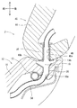
また、シートクッションパッド14の後部には、その厚み方向を貫通するように貫通孔18が形成されている。この貫通孔18の入口18aは、空調装置30に対してホース状の第2のダクト34を介して接続されている。この第2のダクト34も、車両用シート2を折り畳んで格納しても対応可能に十分長く形成されている。なお、この第2のダクト34は、図1からも明らかなように、シートクッションパッド14の外部に配設されている。
A through
一方、この貫通孔18の出口18b側には、シートクッション側筒部材20が挿し込まれる格好で組み付けられている(図2〜3参照)。これにより、着座者の荷重がシートクッションパッド14に掛かっても、シートクッションパッド14が大きく撓むことを規制できる。したがって、貫通孔18の出口18bが塞がれることを防止できる。なお、このようにシートクッション側筒部材20が組み付けられたとき、貫通孔18の出口18b側の内面は、シートクッションパッド14が露出した状態となっている。
On the other hand, the seat cushion
また、この貫通孔18の出口18bの内径は、シートクッション側筒部材20の外径より小さく設定されている。そのため、挿し込まれたシートクッション側筒部材20が貫通孔18の出口18bから抜け難くなっている。また、この貫通孔18の出口18b側は、後述するシートバックパッド44の流路46の入口46aの周囲を覆うようにシートクッションパッド14の後方の上側が盛り上がった形状を成している。シートクッション10は、このように構成されている。
Further, the inner diameter of the
次に、シートバック40を説明する(図1〜2、5参照)。このシートバック40も、略矩形の枠状に形成されたシートバックフレーム42と、このシートバックフレーム42を覆うように組み付けられたシートバックパッド44と、このシートバックパッド44の表面(意匠面)をカバーリングするシートバックカバー(図示しない)とから構成されている。
Next, the seat back 40 will be described (see FIGS. 1 and 2 and 5). The seat back 40 also has a seat back
このシートバックパッド44の背凭れ面には、複数(この例では、7個)の吹出口44aが形成されている。また、このシートバックパッド44の内部には、複数の吹出口44aにそれぞれ連通した流路46が形成されている。この複数の吹出口44aは、流路46の出口となっており、この流路46の入口46aは、シートクッションパッド14の貫通孔18の出口18bに対向するようにシートバックパッド44の下側に形成されている。
A plurality (seven in this example) of
言い換えると、シートクッションパッド14の貫通孔18の出口18bは、シートバックパッド44の流路46の入口46aに対向するように形成されている。これにより、空調装置30を動作させると、第2のダクト34と貫通孔18と流路46とを介して複数の吹出口44aから空調エア(温風エアや冷風エア)Aを吹き出させることができる。このとき、第2のダクト34は、従来技術とは異なり、シートクッションパッド14の外部に配設されている。
In other words, the
そのため、空調エアAの暖気や冷気がシートクッションパッド14に奪われることがない。したがって、シートバック40の複数の吹出口44aから吹き出される空調エアAが生暖かい(生ぬるい)ものとなることがない。結果として、従来技術と同様に、着座者の着座環境を良好に保つことができる。なお、このとき、シートバックパッド44の流路46には、従来技術と同様に、シートクッションパッド14(具体的には、シートクッションパッド14の貫通孔18)を介して空調エアAが供給されている。
Therefore, warm air and cold air of the air-conditioning air A are not taken away by the
そのため、この空調エアAの供給口がシートバック40の意匠面に現れることがない。したがって、車両用シート2の美観が損なわれることを防止できる。また、この流路46の入口46aの縁には、格子を有するベゼル46bが組み付けられている。これにより、流路46に異物が入り込むことを防止できる。また、この流路46の入口46aには、シートバック側筒部材50が挿し込まれる格好で組み付けられている(図2〜3参照)。
Therefore, the supply port of the air-conditioning air A does not appear on the design surface of the seat back 40. Accordingly, it is possible to prevent the appearance of the
これにより、着座者の荷重がシートバックパッド44に掛かっても、シートバックパッド44が大きく撓むことを規制できる。したがって、流路46の入口46aが塞がれることを防止できる。なお、この流路46の入口46aの内径は、シートバック側筒部材50の外径より小さく設定されている。そのため、挿し込まれたシートバック側筒部材50が流路46の入口46aから抜け難くなっている。シートバック40は、このように構成されている。
Thereby, even if a seated person's load is applied to the seat back
本発明の実施例に係る車両用シート2は、上述したように構成されている。この構成によれば、シートクッションパッド14の後部には、その厚み方向を貫通するように貫通孔18が形成されている。この貫通孔18の入口18aは、空調装置30に対してホース状の第2のダクト34を介して接続されている。なお、この第2のダクト34は、シートクッションパッド14の外部に配設されている。また、シートクッションパッド14の貫通孔18の出口18bは、シートバックパッド44の流路46の入口46aに対向するように形成されている。そのため、空調装置30を動作させると、第2のダクト34と貫通孔18と流路46とを介して複数の吹出口44aから空調エア(温風エアや冷風エア)Aを吹き出させることができる。このとき、第2のダクト34は、従来技術とは異なり、シートクッションパッド14の外部に配設されている。そのため、空調エアAの暖気や冷気がシートクッションパッド14に奪われることがない。したがって、シートバック40の複数の吹出口44aから吹き出される空調エアAが生暖かい(生ぬるい)ものとなることがない。結果として、従来技術と同様に、着座者の着座環境を良好に保つことができる。
The
また、この構成によれば、シートバックパッド44の流路46には、従来技術と同様に、シートクッションパッド14(具体的には、シートクッションパッド14の貫通孔18)を介して空調エアAが供給されている。そのため、この空調エアAの供給口がシートバック40の意匠面に現れることがない。したがって、車両用シート2の美観が損なわれることを防止できる。
Further, according to this configuration, the air-conditioning air A is provided in the
また、この構成によれば、シートクッションパッド14の貫通孔18の出口18bには、シートクッション側筒部材20が挿し込まれる格好で組み付けられている。これにより、着座者の荷重がシートクッションパッド14に掛かっても、このシートクッションパッド14が大きく撓むことを規制できる。したがって、このシートクッションパッド14の貫通孔18の出口18bが塞がれることを防止できる。また、この構成によれば、シートバックパッド44の流路46の入口46aには、シートバック側筒部材50が挿し込まれる格好で組み付けられている。これにより、着座者の荷重がシートバックパッド44に掛かっても、このシートバックパッド44が大きく撓むことを規制できる。したがって、このシートバックパッド44の流路46の入口46aが塞がれることを防止できる。
Further, according to this configuration, the seat cushion side
また、この構成によれば、貫通孔18の出口18b側の内面は、シートクッションパッド14が露出した状態となっている。そのため、車両用シート2を折り畳んで格納したとき、シートクッション側筒部材20がシートバック40の堅物(例えば、ベゼル46b)に接触することによって生じる異音や磨耗を防止できる。
According to this configuration, the inner surface of the through
また、この構成によれば、貫通孔18の出口18b側は、シートバックパッド44の流路46の入口46aの周囲を覆うようにシートクッションパッド14の後方の上側が盛り上がった形状を成している。そのため、シートクッション10の貫通孔18と、シートバック40の流路46とを密閉できる。したがって、確実に、空調装置30から発せられる空調エアAをシートバック40の流路46に供給できる。結果として、確実に、空調エアAをシートバック40の吹出口44aから吹き出させることができる。
In addition, according to this configuration, the
上述した内容は、あくまでも本発明の一実施の形態に関するものであって、本発明が上記内容に限定されることを意味するものではない。 The contents described above are only related to one embodiment of the present invention, and do not mean that the present invention is limited to the above contents.
実施例では、『乗物』と『乗物用シート』の例として、『自動車1』と『車両用シート2』とを説明した。しかし、これに限定されるものでなく、各種の乗物、例えば、『船舶』、『飛行機』、『鉄道』等であっても構わない。また、実施例では、『車両用シート』の例として、『タンブルタイプの後部座席』を説明した。しかし、これに限定されるものでなく、各種のシート、例えば、『運転席』、『助手席』等であっても構わない。もちろん、タンブルタイプに限定されることもない。
In the embodiment, “
また、実施例では、空調装置30は、床フロア3に組み付けられている形態を説明した。しかし、これに限定されるものでなく、空調装置30は、シートクッション10に組み付けられていても構わない。
Moreover, in the Example, the
2 車両用シート(乗物用シート)
3 床フロア
10 シートクッション
14 シートクッションパッド
16 流路
16a 入口
18 貫通孔
18a 入口
18b 出口
30 空調装置
34 第2のダクト(ダクト)
A 空調エア
2 Vehicle seat (vehicle seat)
A Air-conditioning air
Claims (4)
前記シートクッションパッドの後部には、その厚み方向を貫通するように貫通孔が形成されており、
前記貫通孔の入口は、前記空調装置に対して前記シートクッションパッドの外部に配設されたダクトを介して繋がっており、
前記貫通孔の出口は、前記シートバックパッドの前記流路の入口に対向するように形成されている乗物用シート。 Air-conditioning air emitted from an air conditioner provided on the floor or seat cushion is a vehicle seat that is supplied to a flow path formed inside the seat back pad of the seat back via the seat cushion pad of the seat cushion. And
A through hole is formed in the rear part of the seat cushion pad so as to penetrate the thickness direction thereof,
The inlet of the through hole is connected to the air conditioner through a duct disposed outside the seat cushion pad,
The vehicle seat, wherein an outlet of the through hole is formed to face an inlet of the flow path of the seat back pad.
前記シートクッションパッドの前記貫通孔の出口側には、前記シートクッションパッドが大きく撓むことを規制するシートクッション側筒部材が設けられ、
前記シートバックパッドの前記流路の入口側には、前記シートバックパッドが大きく撓むことを規制するシートバック側筒部材が設けられている乗物用シート。 The vehicle seat according to claim 1,
On the exit side of the through hole of the seat cushion pad, a seat cushion side cylindrical member that restricts the seat cushion pad from being greatly bent is provided,
A vehicle seat in which a seat back side tubular member is provided on an inlet side of the flow path of the seat back pad to restrict the seat back pad from being greatly bent.
前記シートクッションパッドの前記貫通孔の出口側に前記シートクッション側筒部材が設けられた状態において、前記貫通孔の出口側の内面は、前記シートクッションパッドが露出した状態となっている乗物用シート。 The vehicle seat according to claim 2,
In the state where the seat cushion side cylindrical member is provided on the outlet side of the through hole of the seat cushion pad, the inner surface of the through hole on the outlet side is in a state where the seat cushion pad is exposed. .
前記貫通孔の出口側は、前記シートバックパッドの流路の入口の周囲を覆うように前記シートクッションパッドの後方の上側が盛り上がった形状を成している乗物用シート。
The vehicle seat according to any one of claims 1 to 3,
A vehicle seat in which an outlet side of the through hole has a shape in which a rear upper side of the seat cushion pad is raised so as to cover a periphery of an inlet of a flow path of the seat back pad.
Priority Applications (1)
| Application Number | Priority Date | Filing Date | Title |
|---|---|---|---|
| JP2016106127A JP6641552B2 (en) | 2016-05-27 | 2016-05-27 | Vehicle seat |
Applications Claiming Priority (1)
| Application Number | Priority Date | Filing Date | Title |
|---|---|---|---|
| JP2016106127A JP6641552B2 (en) | 2016-05-27 | 2016-05-27 | Vehicle seat |
Publications (2)
| Publication Number | Publication Date |
|---|---|
| JP2017210190A true JP2017210190A (en) | 2017-11-30 |
| JP6641552B2 JP6641552B2 (en) | 2020-02-05 |
Family
ID=60476579
Family Applications (1)
| Application Number | Title | Priority Date | Filing Date |
|---|---|---|---|
| JP2016106127A Expired - Fee Related JP6641552B2 (en) | 2016-05-27 | 2016-05-27 | Vehicle seat |
Country Status (1)
| Country | Link |
|---|---|
| JP (1) | JP6641552B2 (en) |
Cited By (2)
| Publication number | Priority date | Publication date | Assignee | Title |
|---|---|---|---|---|
| CN112424021A (en) * | 2018-07-17 | 2021-02-26 | 提爱思科技股份有限公司 | Vehicle seat |
| JP7428885B2 (en) | 2020-03-13 | 2024-02-07 | テイ・エス テック株式会社 | vehicle seat |
-
2016
- 2016-05-27 JP JP2016106127A patent/JP6641552B2/en not_active Expired - Fee Related
Cited By (4)
| Publication number | Priority date | Publication date | Assignee | Title |
|---|---|---|---|---|
| CN112424021A (en) * | 2018-07-17 | 2021-02-26 | 提爱思科技股份有限公司 | Vehicle seat |
| CN112424021B (en) * | 2018-07-17 | 2023-05-09 | 提爱思科技股份有限公司 | Vehicle seat |
| US11738671B2 (en) | 2018-07-17 | 2023-08-29 | Ts Tech Co., Ltd. | Padded and ventilated vehicle seat |
| JP7428885B2 (en) | 2020-03-13 | 2024-02-07 | テイ・エス テック株式会社 | vehicle seat |
Also Published As
| Publication number | Publication date |
|---|---|
| JP6641552B2 (en) | 2020-02-05 |
Similar Documents
| Publication | Publication Date | Title |
|---|---|---|
| US10743671B2 (en) | Air conditioning seat | |
| US20180022252A1 (en) | Vehicular seat | |
| JP6652199B2 (en) | Ventilation seat and seat air conditioner | |
| JP2009118947A (en) | Vehicular seat | |
| JP2005287532A (en) | Car seat | |
| JP6766884B2 (en) | Seat air conditioner | |
| JP6423732B2 (en) | Vehicle seat | |
| JP2019093843A (en) | Vehicle seat | |
| JP2016190622A (en) | Vehicle seat | |
| KR101294170B1 (en) | High voltage parts cooling structure of vehicle | |
| JP2018020733A (en) | Vehicle air conditioner | |
| JP2017210190A (en) | Vehicle seat | |
| JP4580672B2 (en) | Vehicle seat and connection structure | |
| US7165808B2 (en) | Rear seat storage console | |
| JP5176588B2 (en) | Sheet blower | |
| JP2011063117A (en) | Air conditioner for vehicle seat | |
| CN104943583B (en) | Seat climate control assembly and seat thereof | |
| JP5343503B2 (en) | Seat and seat air conditioner | |
| JP5994674B2 (en) | Vehicle seat | |
| JP2007320446A (en) | Cabin structure | |
| JP6233293B2 (en) | Air conditioner for vehicles | |
| JP6838429B2 (en) | Air conditioning sheet | |
| JP6930289B2 (en) | Seat | |
| JP2021061875A (en) | Vehicle seat | |
| WO2022244506A1 (en) | Vehicle seat |
Legal Events
| Date | Code | Title | Description |
|---|---|---|---|
| A621 | Written request for application examination |
Free format text: JAPANESE INTERMEDIATE CODE: A621 Effective date: 20181127 |
|
| A977 | Report on retrieval |
Free format text: JAPANESE INTERMEDIATE CODE: A971007 Effective date: 20190919 |
|
| A131 | Notification of reasons for refusal |
Free format text: JAPANESE INTERMEDIATE CODE: A131 Effective date: 20191001 |
|
| A521 | Request for written amendment filed |
Free format text: JAPANESE INTERMEDIATE CODE: A523 Effective date: 20191107 |
|
| TRDD | Decision of grant or rejection written | ||
| A01 | Written decision to grant a patent or to grant a registration (utility model) |
Free format text: JAPANESE INTERMEDIATE CODE: A01 Effective date: 20191119 |
|
| A61 | First payment of annual fees (during grant procedure) |
Free format text: JAPANESE INTERMEDIATE CODE: A61 Effective date: 20191202 |
|
| R151 | Written notification of patent or utility model registration |
Ref document number: 6641552 Country of ref document: JP Free format text: JAPANESE INTERMEDIATE CODE: R151 |
|
| LAPS | Cancellation because of no payment of annual fees |