JP2017100367A - Screen mask and method for producing screen mask - Google Patents
Screen mask and method for producing screen mask Download PDFInfo
- Publication number
- JP2017100367A JP2017100367A JP2015235719A JP2015235719A JP2017100367A JP 2017100367 A JP2017100367 A JP 2017100367A JP 2015235719 A JP2015235719 A JP 2015235719A JP 2015235719 A JP2015235719 A JP 2015235719A JP 2017100367 A JP2017100367 A JP 2017100367A
- Authority
- JP
- Japan
- Prior art keywords
- pattern
- layer
- screen
- hole
- photomask
- Prior art date
- Legal status (The legal status is an assumption and is not a legal conclusion. Google has not performed a legal analysis and makes no representation as to the accuracy of the status listed.)
- Pending
Links
Images
Abstract
Description
本発明はスクリーンマスク及びスクリーンマスクの製造方法に関する。詳しくは、簡易な構造で耐久性に優れ、高精度な印刷を実現可能とするスクリーンマスク及びスクリーンマスクの製造方法に係るものである。 The present invention relates to a screen mask and a method for manufacturing the screen mask. More specifically, the present invention relates to a screen mask that has a simple structure, excellent durability, and capable of realizing high-precision printing, and a method for manufacturing the screen mask.
孔版印刷の一種としてスクリーン印刷が用いられている。スクリーン印刷は、印刷パターンを形成したスクリーンマスクに印刷ペーストを通過させ、被印刷物上に印刷パターンに応じた印刷を行う手法である。 Screen printing is used as a kind of stencil printing. Screen printing is a technique in which a printing paste is passed through a screen mask on which a printing pattern is formed, and printing is performed on a printed material according to the printing pattern.
スクリーン印刷は、幅広い対象物に対して印刷が可能であり、例えば、紙、布、プラスチック、金属、ガラス等に印刷が可能である。近年は、電子部品の製造への用途が拡大しており、チップ部品の配線形成やフラットパネルディスプレイの電極形成、結晶シリコン太陽電池の製造等、高精度な印刷が求められる分野で幅広く使用されている。 Screen printing can be performed on a wide range of objects, for example, printing on paper, cloth, plastic, metal, glass, and the like. In recent years, the application to the manufacture of electronic components has been expanded and widely used in fields that require high-precision printing, such as the formation of wiring for chip components, the formation of electrodes for flat panel displays, and the manufacture of crystalline silicon solar cells. Yes.
スクリーンマスクは主に、枠体、スクリーンメッシュ及び感光性乳剤で構成されている。枠体は、アルミダイキャスト製やアルミパイプ製のものが、スクリーンメッシュはステンレス鋼やタングステン等の金属繊維またはポリエステル等の合成繊維等が用いられている。 The screen mask is mainly composed of a frame, a screen mesh, and a photosensitive emulsion. The frame is made of aluminum die cast or aluminum pipe, and the screen mesh is made of metal fibers such as stainless steel or tungsten, or synthetic fibers such as polyester.
また、感光性乳剤は、露光やレーザー照射により硬化する性質を有している。例えば、PVA、PVAc、シリコン樹脂、アクリル樹脂、エポキシ樹脂等の光硬化性の樹脂組成物が用いられる。 The photosensitive emulsion has the property of being cured by exposure or laser irradiation. For example, a photocurable resin composition such as PVA, PVAc, silicon resin, acrylic resin, or epoxy resin is used.
スクリーンマスクの製造では、枠体にスクリーンメッシュを接着剤で固定し、スクリーンメッシュの表面に感光性乳剤をコーティングして層を形成する。この層にフィルムやガラスにパターン形成されたフォトマスクを重ねて、露光もしくはレーザー照射によって感光させ印刷パターンを形成し、水等の現像液にて現像がなされる。 In the production of a screen mask, a screen mesh is fixed to a frame with an adhesive, and a photosensitive emulsion is coated on the surface of the screen mesh to form a layer. A photomask patterned on a film or glass is superimposed on this layer and exposed to light by exposure or laser irradiation to form a printed pattern, which is developed with a developer such as water.
印刷時は、スクリーンマスク上に印刷ペーストを塗布し、ウレタンゴム等のスキージをスライドさせながら圧力をかけ、転写のメカニズムで被印刷物上に印刷ペーストが印刷されるものとなる。 At the time of printing, a printing paste is applied on a screen mask, pressure is applied while sliding a squeegee such as urethane rubber, and the printing paste is printed on the substrate by a transfer mechanism.
近年の高精細な印刷に用いるスクリーンマスクの作製では、感光性乳剤を使用してパターン形成を行うことが一般的である。しかしながら、感光性乳剤の硬度が低いため、印刷やマスクの洗浄によって、パターン形成された感光性乳剤部の磨耗や変形が生じていた。 In the production of a screen mask used for high-definition printing in recent years, it is common to form a pattern using a photosensitive emulsion. However, since the hardness of the photosensitive emulsion is low, the patterned photosensitive emulsion portion is worn or deformed by printing or mask cleaning.
この結果、印刷ずれの発生や、平面度の劣化によるスクリーンマスクへの損傷が増加し、比較的短期間でスクリーンマスクの交換を行わなければならない問題があった。 As a result, the occurrence of printing misalignment and the damage to the screen mask due to the deterioration of flatness increase, and there is a problem that the screen mask must be replaced in a relatively short period of time.
こうしたなか、パターン形成された感光性乳剤とスクリーンメッシュの表面を耐摩耗性、耐食性、潤滑性に優れた保護膜で被覆したスクリーンマスクが提案され、例えば、特許文献1に記載のスクリーンマスクが存在する。 Under such circumstances, a screen mask in which the surface of the patterned photosensitive emulsion and the screen mesh is covered with a protective film having excellent wear resistance, corrosion resistance, and lubricity has been proposed. For example, there is a screen mask described in Patent Document 1 To do.
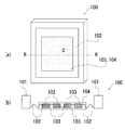
図9に示すように、特許文献1に記載されたスクリーンマスク100は、枠体101に設けられたスクリーンメッシュ102上の感光性乳剤103に所定のパターンが形成されている。感光性乳剤103は、印刷ペーストが通過しない硬化した感光性乳剤部と、印刷ペーストが通過するメッシュ部で構成される。
As shown in FIG. 9, the
また、スクリーンマスク100は、枠体101の中央部にある感光性乳剤部103とその周りにあるスクリーンメッシュ102に、耐摩耗性、耐食性及び潤滑性に優れた保護膜104が形成されている。
In the
保護膜104は、スクリーンマスクにプラズマ発生用原料ガスの含炭素化合物ガスを用いたプラズマ処理を施し、感光性乳剤および紗の表面を改質して形成されるものとなっている。
The
しかしながら、特許文献1に記載のスクリーンマスクは保護膜の形成のためにプラズマ処理装置が必要となる。また、多数の印刷パターンを要する用途では、複数の印刷パターンに応じたスクリーンマスクの製造が必要となるため、製造に費用や時間がかかるものとなる。 However, the screen mask described in Patent Document 1 requires a plasma processing apparatus for forming a protective film. Further, in applications that require a large number of print patterns, it is necessary to manufacture a screen mask according to a plurality of print patterns.
また、従来のスクリーンマスクでは、被印刷物上やその周辺に存在する異物がスクリーンマスクに接触して損傷を生じることがある。異物はセラミックや金属片、印刷ペーストの塊等があり、その大きさも数十μmから数mmまで種々存在する。また、被印刷物自体の凸状部の接触も損傷につながる。 Moreover, in the conventional screen mask, the foreign substance which exists on the to-be-printed material or its periphery may contact a screen mask and may be damaged. The foreign matter includes ceramics, metal pieces, a lump of printing paste, and the like. Further, the contact of the convex portion of the printing material itself also leads to damage.
損傷により感光性乳剤の表面にクラックが生じ、その部分から印刷ペーストが漏れ、印刷不良を起こすものとなる。また、損傷がひどい場合には、スクリーンメッシュが切れ、スクリーンマスク自体が割れてしまう不都合も生じる。 Damage causes cracks on the surface of the photosensitive emulsion, and the printing paste leaks from the cracks, resulting in poor printing. In addition, when the damage is severe, the screen mesh is cut and the screen mask itself is broken.
また、一般的に、スクリーンマスクの面積は被印刷物の面積より大きくなっている。被印刷物の周辺に位置する異物の量は、印刷回数の増加に伴って増えるため、スクリーンマスクの被印刷物より外側の領域により損傷が生じるやすいものとなる。 In general, the area of the screen mask is larger than the area of the substrate. Since the amount of foreign matter located around the substrate to be printed increases as the number of times of printing increases, damage is likely to occur in an area outside the substrate to be printed on the screen mask.
スクリーンマスクの損傷した箇所に、硬化性の液体や粘着テープで応急処置をする方法もあるが、印刷パターンに悪影響を及ぼすため、現実的には採用し難いものであった。 There is also a method of giving first aid to the damaged part of the screen mask with a curable liquid or an adhesive tape, but it has an adverse effect on the printing pattern, so it is difficult to adopt in practice.
本発明は、以上の点に鑑みて創案されたものであり、簡易な構造で耐久性に優れ、高精度な印刷を実現可能とするスクリーンマスク及びスクリーンマスクの製造方法に係るものである。 The present invention has been devised in view of the above points, and relates to a screen mask and a method for manufacturing the screen mask that can realize high-precision printing with a simple structure, excellent durability, and the like.
上記の目的を達成するために、本発明のスクリーンマスクは、枠体と、該枠体内に張設されたスクリーンメッシュと、該スクリーンメッシュに設けられ、第1のパターン孔が形成された第1のパターン層と、該第1のパターン層の前記枠体とは反対側の面に設けられると共に、前記第1のパターン孔と対応する位置に第2のパターン孔が形成された第2のパターン層とを備える。 In order to achieve the above object, a screen mask of the present invention includes a frame, a screen mesh stretched in the frame, and a first pattern hole provided on the screen mesh and formed with a first pattern hole. And a second pattern in which a second pattern hole is formed at a position corresponding to the first pattern hole, on the surface of the first pattern layer opposite to the frame body. And a layer.
ここで、枠体と、枠体内に張設されたスクリーンメッシュによってスクリーンマスクの基礎を形成するものとなる。 Here, the base of the screen mask is formed by the frame and the screen mesh stretched in the frame.
また、スクリーンメッシュに設けられ、第1のパターン孔が形成された第1のパターン層によって、第1のパターン孔に応じた印刷パターンが被印刷物に印刷可能となる。即ち、第1のパターン孔を介して印刷ペーストを被印刷物側へと移動せしめるものとなる。なお、第1のパターン孔とは、所定のパターンを形成する孔全体を指すものを意味する。 Moreover, the printing pattern according to the 1st pattern hole can be printed on a to-be-printed object by the 1st pattern layer provided in the screen mesh and in which the 1st pattern hole was formed. That is, the printing paste is moved to the substrate side through the first pattern hole. In addition, the 1st pattern hole means what refers to the whole hole which forms a predetermined pattern.
また、第1のパターン層の枠体とは反対側の面に設けられた第2のパターン層によって、スクリーンメッシュ及び第1のパターン層が受ける損傷を低減させることができる。即ち、印刷時に、スクリーンメッシュ及び第1のパターン層と、被印刷物との間に第2のパターン層が位置するものとなり、結果としてスクリーンマスクの耐久性を向上せしめることが可能となる。 Moreover, the damage which a screen mesh and a 1st pattern layer receive by the 2nd pattern layer provided in the surface on the opposite side to the frame of a 1st pattern layer can be reduced. That is, at the time of printing, the second pattern layer is located between the screen mesh and the first pattern layer and the printing material, and as a result, the durability of the screen mask can be improved.
また、第1のパターン層の枠体とは反対側の面に設けられると共に、第1のパターン孔と対応する位置に第2のパターン孔が形成された第2のパターン層によって、スクリーンメッシュ及び第1のパターン層を損傷から保護しながら、第1のパターン孔に応じた印刷パターンが被印刷物に印刷可能となる。なお、第2のパターン孔とは、第1のパターン孔と対応する位置に設けられた孔であり、所定のパターンを形成する孔全体を指すものを意味する。 The screen pattern and the second pattern layer provided on the surface of the first pattern layer opposite to the frame and having the second pattern hole formed at a position corresponding to the first pattern hole. A print pattern corresponding to the first pattern hole can be printed on the printing material while protecting the first pattern layer from damage. The second pattern hole is a hole provided at a position corresponding to the first pattern hole, and means a whole hole that forms a predetermined pattern.
また、第2のパターン孔の孔径が第1のパターン孔の孔径よりも大きく形成された場合には、第1のパターン孔と第2のパターン孔が面一とならず、第1のパターン孔を介した印刷精度を高めることができる。即ち、被印刷物上の印刷ペーストの厚みや形状が第2のパターン孔と接触して変形する等の影響を減らすことができる。 Further, when the hole diameter of the second pattern hole is formed larger than the hole diameter of the first pattern hole, the first pattern hole and the second pattern hole are not flush with each other. The printing accuracy via can be improved. That is, it is possible to reduce the influence of the deformation and the like of the thickness and shape of the printing paste on the printing material in contact with the second pattern hole.
また、第2のパターン孔の外周面と第1のパターン孔の外周面との間の距離が20μm以上である場合には、スクリーンメッシュ及び第1のパターン層を損傷からより保護しやすく、第1のパターン孔の印刷精度も向上させることができる。 Further, when the distance between the outer peripheral surface of the second pattern hole and the outer peripheral surface of the first pattern hole is 20 μm or more, the screen mesh and the first pattern layer can be more easily protected from damage, The printing accuracy of one pattern hole can also be improved.
一方、第2のパターン孔の外周面と第1のパターン孔の外周面との間の距離が20μm未満である場合には、第2のパターン孔と被印刷物上の印刷ペーストが接触しやすくなり、印刷後の印刷ペーストの厚みや形状が変形しやすいものとなってしまう。 On the other hand, when the distance between the outer peripheral surface of the second pattern hole and the outer peripheral surface of the first pattern hole is less than 20 μm, the second pattern hole and the printing paste on the substrate are likely to come into contact with each other. Thus, the thickness and shape of the printed paste after printing are likely to be deformed.
また、第1のパターン層の外周部に位置決め用の線が設けられた場合には、第1のパターン孔と第2のパターン孔の位置のずれが生じにくいものとなる。即ち、例えば、第1のパターン層及び第2のパターン層を形成するそれぞれのフォトマスクの外周部にパターンとして位置決め用の線を設けておくことで、感光後に第1のパターン層の外周部に位置決め用の線が形成され、更に、第1のパターン層の位置決め用の線と第2のパターン層を形成するフォトマスクの位置決め用の線を合わせることで、第1のパターン層と第2のパターン層の位置がずれにくいものとなる。 In addition, when a positioning line is provided on the outer peripheral portion of the first pattern layer, the positional shift between the first pattern hole and the second pattern hole hardly occurs. That is, for example, a positioning line is provided as a pattern on the outer periphery of each photomask that forms the first pattern layer and the second pattern layer, so that the outer periphery of the first pattern layer is exposed after exposure. A positioning line is formed, and further, the first pattern layer and the second pattern layer are aligned by aligning the positioning line of the first pattern layer with the positioning line of the photomask forming the second pattern layer. The position of the pattern layer is difficult to shift.
また、上記の目的を達成するために、本発明のスクリーンマスクは、枠体と、該枠体内に張設されたスクリーンメッシュと、該スクリーンメッシュに設けられ、その中央領域に第1のパターン孔が形成された第1のパターン層と、該第1のパターン層の前記枠体とは反対側の面かつ前記第1のパターン孔よりも外側の領域に設けられた第2のパターン層とを備える。 In order to achieve the above object, the screen mask of the present invention is provided with a frame, a screen mesh stretched in the frame, the screen mesh, and a first pattern hole in a central region thereof. And a second pattern layer provided in a region on the opposite side of the first pattern layer from the frame body and in a region outside the first pattern hole. Prepare.
ここで、第1のパターン層の枠体とは反対側の面かつ第1のパターン孔よりも外側の領域に設けられた第2のパターン層によって、被印刷物の外側に位置する異物からの損傷に対応しやすいものとなる。即ち、スクリーンマスクの外周近傍の領域を保護する構造となる。 Here, the damage from the foreign matter located outside the substrate by the second pattern layer provided on the surface opposite to the frame of the first pattern layer and on the outside of the first pattern hole. It becomes easy to cope with. That is, it becomes a structure that protects a region near the outer periphery of the screen mask.
また、上記の目的を達成するために、本発明のスクリーンマスクの製造方法は、枠体内にスクリーンメッシュを固定する第1の工程と、前記スクリーンメッシュに第1のパターン層となる感光性乳剤の層を設ける第2の工程と、該第2の工程で設けた感光性乳剤の層に、第1のフォトマスクを重ねて光線を照射し、第1のパターン孔が形成された第1のパターン層とする第3の工程と、前記第1のパターン層に第2のパターン層となる感光性乳剤の層を設ける第4の工程と、該第4の工程で設けた感光性乳剤の層に、第2のフォトマスクを重ねて光線を照射し、前記第1のパターン孔に対応する第2のパターン孔が形成された第2のパターン層とする第5の工程とを備える。 In order to achieve the above object, a method for producing a screen mask according to the present invention includes a first step of fixing a screen mesh in a frame body, and a photosensitive emulsion serving as a first pattern layer on the screen mesh. A second step of providing a layer, and a first pattern in which a first photomask is applied to the layer of the photosensitive emulsion provided in the second step and irradiated with light to form a first pattern hole A third step of forming a layer, a fourth step of providing a photosensitive emulsion layer as a second pattern layer in the first pattern layer, and a layer of the photosensitive emulsion provided in the fourth step. And a fifth step of forming a second pattern layer in which a second pattern hole corresponding to the first pattern hole is formed by irradiating the second photomask with a light beam.
ここで、枠体内にスクリーンメッシュを固定する第1の工程によって、スクリーンマスクの基礎を形成することができる。 Here, the basis of the screen mask can be formed by the first step of fixing the screen mesh in the frame.
また、スクリーンメッシュに第1のパターン層となる感光性乳剤の層を設ける第2の工程と、第2の工程で設けた感光性乳剤の層に、第1のフォトマスクを重ねて光線を照射し、第1のパターン孔が形成された第1のパターン層とする第3の工程によって、第1のパターン孔に応じた印刷パターンが被印刷物に印刷可能な第1のパターン層を形成することができる。なお、第1のパターン孔とは、所定のパターンを形成する孔全体を指すものを意味する。また、ここでいう光線とは、紫外線及び可視光を含むものを意味するものである。 In addition, a second step of providing a photosensitive emulsion layer serving as a first pattern layer on the screen mesh, and a light beam is applied by overlapping the first photomask on the photosensitive emulsion layer provided in the second step. And forming the first pattern layer on which the print pattern corresponding to the first pattern hole can be printed on the printing material by the third step of forming the first pattern layer in which the first pattern hole is formed. Can do. In addition, the 1st pattern hole means what refers to the whole hole which forms a predetermined pattern. Moreover, the light ray here means a thing containing ultraviolet rays and visible light.
また、第1のパターン層に第2のパターン層となる感光性乳剤の層を設ける第4の工程と、第4の工程で設けた感光性乳剤の層に、第2のフォトマスクを重ねて光線を照射し、第2のパターン層とする第5の工程によって、スクリーンメッシュ及び第1のパターン層と、被印刷物との間に位置する第2のパターン層を形成することができる。即ち、スクリーンメッシュ及び第1のパターン層が受ける損傷を低減させる構造とすることができる。 In addition, a fourth step of providing a photosensitive emulsion layer to be a second pattern layer on the first pattern layer, and a second photomask are superimposed on the photosensitive emulsion layer provided in the fourth step. The second pattern layer positioned between the screen mesh, the first pattern layer, and the printing material can be formed by the fifth step of irradiating light to form the second pattern layer. That is, a structure that reduces damage to the screen mesh and the first pattern layer can be obtained.
また、第1のパターン層に第2のパターン層となる感光性乳剤の層を設ける第4の工程と、第4の工程で設けた感光性乳剤の層に、第2のフォトマスクを重ねて光線を照射し、第1のパターン孔に対応する第2のパターン孔が形成された第2のパターン層とする第5の工程によって、スクリーンメッシュ及び第1のパターン層を損傷から保護しながら、第1のパターン孔に応じた印刷パターンが被印刷物に印刷可能なスクリーンマスクを形成可能となる。なお、第2のパターン孔とは、第1のパターン孔と対応する位置に設けられた孔であり、所定のパターンを形成する孔全体を指すものを意味する。 In addition, a fourth step of providing a photosensitive emulsion layer to be a second pattern layer on the first pattern layer, and a second photomask are superimposed on the photosensitive emulsion layer provided in the fourth step. While protecting the screen mesh and the first pattern layer from damage by the fifth step of irradiating the light beam and forming the second pattern layer in which the second pattern hole corresponding to the first pattern hole is formed, It becomes possible to form a screen mask capable of printing a printing pattern corresponding to the first pattern hole on the substrate. The second pattern hole is a hole provided at a position corresponding to the first pattern hole, and means a whole hole that forms a predetermined pattern.
また、第2のパターン孔の孔径が第1のパターン孔の孔径よりも大きく形成された場合には、第1のパターン孔と第2のパターン孔が面一とならず、第1のパターン孔を介した印刷精度を高めることができる。即ち、被印刷物上の印刷ペーストの厚みや形状が第2のパターン孔と接触して変形する等の影響を減らすことができる。 Further, when the hole diameter of the second pattern hole is formed larger than the hole diameter of the first pattern hole, the first pattern hole and the second pattern hole are not flush with each other. The printing accuracy via can be improved. That is, it is possible to reduce the influence of the deformation and the like of the thickness and shape of the printing paste on the printing material in contact with the second pattern hole.
また、第2の工程でスクリーンメッシュにシート状の感光性乳剤を貼り付ける場合には、第1のパターン層の同一層内での乳剤厚みが均一なものとなる。この結果、印刷時にインク転写膜厚を均一なものとすることができる。また、乳剤表面の平滑性が向上するものとなる。この結果、印刷時のインク滲みが低減でき、直線性のよいシャープな印刷が可能となる。即ち、インク膜厚と幅方向の均一性を向上させ、印刷精度を高めることができる。 When a sheet-like photosensitive emulsion is pasted on the screen mesh in the second step, the emulsion thickness in the same layer of the first pattern layer is uniform. As a result, the ink transfer film thickness can be made uniform during printing. Further, the smoothness of the emulsion surface is improved. As a result, ink bleeding during printing can be reduced, and sharp printing with good linearity can be achieved. That is, the ink film thickness and the uniformity in the width direction can be improved, and the printing accuracy can be increased.
また、第4の工程で第1のパターン層にシート状の感光性乳剤を貼り付ける場合には、第2のパターン層の同一層内での乳剤厚みが均一なものとなる。この結果、印刷時にインク転写膜厚を均一なものとすることができる。また、乳剤表面の平滑性が向上するものとなる。この結果、印刷時のインク滲みが低減でき、直線性のよいシャープな印刷が可能となる。即ち、インク膜厚と幅方向の均一性を向上させ、印刷精度を高めることができる。 Further, when a sheet-like photosensitive emulsion is pasted on the first pattern layer in the fourth step, the emulsion thickness in the same layer of the second pattern layer becomes uniform. As a result, the ink transfer film thickness can be made uniform during printing. Further, the smoothness of the emulsion surface is improved. As a result, ink bleeding during printing can be reduced, and sharp printing with good linearity can be achieved. That is, the ink film thickness and the uniformity in the width direction can be improved, and the printing accuracy can be increased.
また、第1のフォトマスク及び前記第2のフォトマスクは位置決め用の線が設けられ、第3の工程で、第1のパターン層に第1のフォトマスクの位置決め用の線に対応した第1のパターン線を形成し、第5の工程で、第1のパターン線と第2のフォトマスクの位置決め用の線を合わせて第2のフォトマスクを重ねる場合には、第1のパターン孔と第2のパターン孔の位置のずれが少ないスクリーンマスクを形成可能となる。即ち、第1のパターン層の位置決め用の線と第2のフォトマスクの位置決め用の線を合わせることで、第1のパターン層と第2のパターン層の位置がずれにくくなり、この結果、第1のパターン孔と第2のパターン孔の位置のずれが少ないものとなる。 The first photomask and the second photomask are provided with positioning lines. In the third step, the first photomask corresponds to the first photomask positioning lines in the first pattern layer. In the fifth step, the first pattern hole and the second photomask are overlapped with each other by aligning the first pattern line and the second photomask positioning line. Therefore, it is possible to form a screen mask with little displacement of the pattern hole positions. That is, by aligning the positioning line of the first pattern layer and the positioning line of the second photomask, the positions of the first pattern layer and the second pattern layer are less likely to be displaced. The positional deviation between the first pattern hole and the second pattern hole is small.
また、上記の目的を達成するために、本発明のスクリーンマスクは、枠体と、該枠体の内側に張設されたスクリーンメッシュと、該スクリーンメッシュに設けられ、パターン孔が形成されると共に、パターン孔の非形成領域の厚みがパターン孔の形成領域周辺の厚みよりも大きく形成されたパターン層とを備える。 In order to achieve the above object, the screen mask of the present invention is provided with a frame, a screen mesh stretched inside the frame, and provided on the screen mesh to form pattern holes. And a pattern layer formed so that the thickness of the non-pattern hole forming region is larger than the thickness around the pattern hole forming region.
ここで、枠体と、枠体の内側に張設されたスクリーンメッシュによって、スクリーンマスクの基礎を形成するものとなる。 Here, the basis of the screen mask is formed by the frame and the screen mesh stretched inside the frame.
また、スクリーンメッシュに設けられ、パターン孔が形成されたパターン層によって、パターン孔に応じた印刷パターンが被印刷物に印刷可能となる。即ち、パターン孔を介して印刷ペーストを被印刷物側へと移動せしめるものとなる。なお、パターン孔とは、所定のパターンを形成する孔全体を指すものを意味する。 Moreover, the printing layer according to the pattern hole can be printed on the printing material by the pattern layer provided on the screen mesh and having the pattern hole formed therein. That is, the printing paste is moved to the substrate side through the pattern holes. In addition, a pattern hole means what refers to the whole hole which forms a predetermined pattern.
また、スクリーンメッシュに設けられ、パターン孔が形成されると共に、パターン孔の非形成領域の厚みがパターン孔の形成領域周辺の厚みよりも大きく形成されたパターン層によって、スクリーンメッシュが受ける損傷を低減させることができる。また、パターン層の耐久性を高めることができる。なお、パターン孔の非形成領域とは、パターン層の内のパターン孔が存在しない部分であり、パターン孔及びパターン孔近傍部分はパターン孔の非形成領域に含まれない部分を意味するものである。 In addition, the pattern mesh is formed on the screen mesh to form pattern holes, and the pattern layer formed so that the thickness of the non-pattern hole forming area is larger than the thickness around the pattern hole forming area reduces damage to the screen mesh. Can be made. Further, the durability of the pattern layer can be increased. The pattern hole non-formation region is a portion of the pattern layer where there is no pattern hole, and the pattern hole and the portion near the pattern hole mean a portion not included in the pattern hole non-formation region. .
本発明に係るスクリーンマスクは、簡易な構造で耐久性に優れ、高精度な印刷を実現可能となっている。
また、本発明に係るスクリーンマスクの製造方法は、簡易な構造で耐久性に優れ、高精度な印刷を実現可能となっている。
The screen mask according to the present invention has a simple structure, excellent durability, and high-precision printing.
In addition, the method for manufacturing a screen mask according to the present invention has a simple structure, excellent durability, and high-precision printing.
以下、本発明の実施の形態について図面を参照しながら説明し、本発明の理解に供する。
図1は、本発明を適用したスクリーンマスクを示す概略図である。なお、以下に示す構造は本発明の一例であり、本発明の内容はこれに限定されるものではない。
Hereinafter, embodiments of the present invention will be described with reference to the drawings to facilitate understanding of the present invention.
FIG. 1 is a schematic view showing a screen mask to which the present invention is applied. In addition, the structure shown below is an example of this invention and the content of this invention is not limited to this.
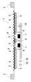
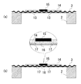
図1に示すように、本発明を適用したスクリーンマスクの一例であるスクリーンマスク1は、フレーム2、スクリーンメッシュ3、第1のスクリーン層4及び第2のスクリーン層5を有している。
As shown in FIG. 1, a screen mask 1 that is an example of a screen mask to which the present invention is applied includes a
スクリーンマスク1は、第2のスクリーン層5と対向する位置に配置された被印刷物6に対して、所定のパターン孔から印刷ペースト7(インク)を印刷する。印刷時は、スクリーンメッシュ3上の印刷ペーストを、スキージ(図示せず)をスライドさせながらパターン孔から押し出していくものとなる。
The screen mask 1 prints a printing paste 7 (ink) from a predetermined pattern hole on a
フレーム2は四角枠状の形状を有しており、例えば、アルミダイキャスト製やアルミパイプ製のものが使用される。また、フレーム2の形状や大きさは、対象となる被印刷物の大きさや、スクリーンマスク1を設置する印刷機械の種類により適宜変更されるものである。
The
スクリーンメッシュ3は、後述する所定のパターン孔が形成されたスクリーン層を支持する部分である。スクリーンメッシュ3に一定の値の張力をかけ、両端部がフレーム2に接着剤で固定されている。スクリーンメッシュ3はフレーム2の内側に配置される。
The
スクリーンメッシュ3はステンレス鋼やタングステン等の金属繊維またはポリエステル等の合成繊維等で形成されている。また、スクリーンメッシュ3は、印刷ペースト7が透過可能な孔部を多数有するメッシュ状に形成されている。フレーム2及びスクリーンメッシュ3がスクリーンマスク1の基板となる部材である。
The
第1のスクリーン層4は、スクリーンメッシュ3に感光性乳剤が板状に設けられた部材である。第1のスクリーン層4には、被印刷物に所望の印刷を可能とするパターン孔8が形成されている。このパターン孔8が、印刷ペーストが通過し、被印刷物6の表面に回路や基板のパターン等を描画させる部分となる。そのため、パターン孔8とは、複数の孔部から構成されたものを意味する。
The
また、第1のスクリーン層4を構成する感光性乳剤は、露光やレーザー照射により硬化する性質を有している。例えば、ポリビニルアルコール(PVA)、ポリ酢酸ビニル(PVAc)、シリコン樹脂、アクリル樹脂、エポキシ樹脂等の光硬化性の樹脂組成物が用いられる。露光作業により硬化した箇所は印刷ペースト7が透過できない部分となる。第1のスクリーン層4は、メッシュとの密着性、弾力性及び解像性に優れるものであることが好ましい。
The photosensitive emulsion constituting the
第2のスクリーン層5は第1のスクリーン層4上に位置し、第1のスクリーン層4と同様、感光性乳剤が板状に設けられた部材である。第2のスクリーン層5は、被印刷物6の上の異物10や、被印刷物より外側の領域にある異物10と接触する層である。即ち、第1のスクリーン層4やスクリーンメッシュ3を異物10との接触から保護する層となる。
The
スクリーンマスク1では、第2のスクリーン層5がスクリーンマスク1の中央部分に形成されている。そのため、第1のスクリーン層4のパターン孔8が形成された領域以外のほとんどの部分を第2のスクリーン層5が覆った形状となっている。
In the screen mask 1, the
また、第2のスクリーン層5にはパターン孔9が形成されている。このパターン孔9は第1のスクリーン層4のパターン孔8と対応する位置に設けられている。
Further, pattern holes 9 are formed in the
より具体的には、第1のスクリーン層4及び第2のスクリーン層5が重なった状態の平面視で、パターン孔8とパターン孔9の位置はほぼ一致するものとなる。パターン孔9も印刷ペーストが通過する部分であり、複数の孔部から構成されている。
More specifically, the positions of the pattern holes 8 and the pattern holes 9 substantially coincide with each other in a plan view in a state where the
上述したようにパターン孔8とパターン孔9の位置はほぼ一致するものであるが、パターン孔9の孔径はパターン孔8の孔径より大きく形成されている。対応する孔同士の位置関係で示すと、図1の矢印Zの箇所で20μmのずれを有するものとなっている。
As described above, the positions of the
また、第2のスクリーン層5を構成する感光性乳剤は、露光やレーザー照射により硬化する性質を有している。第1のスクリーン層4を構成する感光性乳剤と同様に、例えば、ポリビニルアルコール(PVA)、ポリ酢酸ビニル(PVAc)、シリコン樹脂、アクリル樹脂、エポキシ樹脂等の光硬化性の樹脂組成物が用いられる。第2のスクリーン層5は、耐溶剤性及び機械的耐久性に優れるものであることが好ましい。
The photosensitive emulsion constituting the
感光性乳剤の露光作業により硬化した箇所は印刷ペースト7が透過できない部分となる。第1のスクリーン層4及び第2のスクリーン層5を構成する感光性乳剤は同一の素材であってもよいし、各々が異なる異種素材であってもよい。2つの層で異種素材を採用する場合には、上述したような、第1のスクリーン層4に求められるメッシュとの密着性、弾力性及び解像性に優れる性質に特徴を有する素材と、第2のスクリーン層5に求められる耐溶剤性及び機械的耐久性に優れる性質に特徴を有する素材を組み合わせることで、印刷精度や耐久性に優れたスクリーンマスクを製造可能となる。
A portion cured by the exposure operation of the photosensitive emulsion is a portion through which the
また、第1のスクリーン層4と第2のスクリーン層5は、数μm〜100μm程度の厚みを有するものとなっている。なお、スクリーンマスク1では、第1のスクリーン層4の厚みが20μm、第2のスクリーン層5の厚みが30μmの値で形成されている。
In addition, the
ここで、パターン孔8及びパターン孔9の大きさや形成箇所は限定されるものではなく、被印刷物に描画したい所望のパターンに応じて適宜変更されるものである。
Here, the size and formation location of the
また、必ずしも、パターン孔8とパターン孔9で対応する孔同士の位置のずれが20μmとなっている必要はない。パターン孔8を介した印刷に影響しにくいものとなっていれば充分であり、例えば、100μmや1mm程度のずれであってもよい。一方、ずれの大きさが20μm未満になると、パターン孔9が印刷精度に影響するおそれがあるため、対応する孔同士の位置のずれが20μmとなることが好ましい。
Further, the positional deviation between the corresponding holes in the
また、第1のスクリーン層4及び第2のスクリーン層5の厚みは限定されるものではなく、被印刷物や印刷ペーストの種類、発生しやすい異物の種類や大きさ等に応じて適宜変更可能となっている。
Further, the thicknesses of the
また、必ずしも、第1のスクリーン層4と第2のスクリーン層5が異なる2層として形成される必要はなく、例えば、2つの層が一体化した構造であってもよい。
In addition, the
また、必ずしも、スクリーン層の数が第1のスクリーン層4と第2のスクリーン層5の2層に限定される必要はない。例えば、第2のスクリーン層5の更に上に第3のスクリーン層やそれ以上の層を形成してもよい。但し、製造時の工程数が増える点や、第2のスクリーン層5の厚みを変えて保護能を調節しうる点から、スクリーン層の数は2層で充分である。
In addition, the number of screen layers is not necessarily limited to the two layers of the
また、必ずしも、第2のスクリーン層5がスクリーンマスク1の中央部分に形成される必要はない。但し、第1のスクリーン層4やスクリーンメッシュ3の保護がより一層充分になる点で、第2のスクリーン層5がスクリーンマスク1の中央部分に形成されることが好ましい。
In addition, the
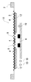
一方、本発明を適用したスクリーンマスクの他の実施の形態として、以下のような構成も採用しうる。以下、図2を用いて説明する。 On the other hand, as another embodiment of the screen mask to which the present invention is applied, the following configuration may be employed. Hereinafter, a description will be given with reference to FIG.
スクリーンマスクの損傷の原因となる異物は、印刷回数を重ねることで、被印刷物の外側の領域に増加していく傾向にある。また、一般的に、スクリーン層のパターン孔は平面視でスクリーン層の中央側に形成され、スクリーン層の外側にはパターン孔が存在しない構造となっている。 Foreign matter that causes damage to the screen mask tends to increase in the area outside the substrate by repeated printing. In general, the pattern hole of the screen layer is formed on the center side of the screen layer in plan view, and has a structure in which no pattern hole exists outside the screen layer.
そこで、本発明の他の実施の形態として、図2に示すスクリーンマスク11も考えられる。スクリーンマスク11は、第1のスクリーン層4のパターン孔8が設けられた領域の外側に第2のスクリーン層12が形成されている。
Therefore, a
第2のスクリーン層12は、被印刷物6の外側の異物10から第1のスクリーン層4やスクリーンメッシュ3を保護可能な構造となっている。なお、スクリーンマスク11の構造のその他の部分は、上述したスクリーンマスク1と共通しているため説明を省略する。
The
以上までで説明した本発明を適用したスクリーンマスクの製造方法について、以下詳細を説明する。
なお、本発明を適用したスクリーンマスクの製造方法は以下に記載する内容に限定されるものではなく、適宜変更しうるものである。
Details of the method for manufacturing a screen mask to which the present invention described above is applied will be described below.
In addition, the manufacturing method of the screen mask to which this invention is applied is not limited to the content described below, It can change suitably.
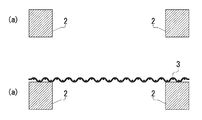
1.ストレッチ作業
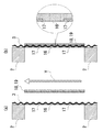
まず、スクリーンマスク1の枠となるフレーム2を洗浄し、図3(a)及び図3(b)に示すように、スクリーンメッシュ3の取り付けを行う。スクリーンメッシュ3はスクリーンマスク1のユーザーの指定及び素材の種類に応じた指定値の張力で引っ張り、テンションをかけながら、フレーム2に接着剤で固定する。
1. Stretching operation First, the
2.コート作業(1層目)
スクリーンメッシュ3の被印刷物と対向する側の面に、第1のスクリーン層4となる感光性乳剤の層13をコート作業にて形成する。感光性乳剤は、例えば、光硬化性のPVA等が使用でき、感光性乳剤の層をユーザーが指定する乳剤膜厚となるように形成する。
2. Coat work (first layer)
On the surface of the
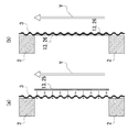
本コート作業は、図4(a)に示すシート状の感光性乳剤の貼り付け、または、図4(b)に示す感光性乳剤の塗布による方法が採用しうる。 For this coating operation, a method of sticking a sheet-like photosensitive emulsion shown in FIG. 4A or applying a photosensitive emulsion shown in FIG. 4B can be employed.
図4(a)に示す方法は、所望の乳剤膜厚を有するシート状の感光性乳剤をスクリーンメッシュ3の面に貼り付けるものである。貼り付けは、垂直にしたスクリーンメッシュ3に液状の感光性乳剤を塗って、スクリーンメッシュ2の下方から感光性乳剤のフィルムシート25を貼り付けていく。
In the method shown in FIG. 4A, a sheet-like photosensitive emulsion having a desired emulsion film thickness is pasted on the surface of the
フィルムシート25の貼り付けは、図4(a)の矢印Yで示す方向に下方から上方へと行う。一定の膜厚に形成したフィルムシート25を用いることで、第1のスクリーン層4の膜厚のばらつきを低減可能となる。
The film sheet 25 is attached from the bottom to the top in the direction indicated by the arrow Y in FIG. By using the film sheet 25 formed to have a constant film thickness, variations in the film thickness of the
一方、図4(b)に示すように、スクリーンメッシュ3に対して液状の感光性乳剤26を平板状に塗布するコート作業であってもよい。この場合、感光性乳剤の塗布と乾燥を繰り返し行い、所望の乳剤膜厚になるまで作業を行う。
On the other hand, as shown in FIG. 4B, a coating operation in which the liquid photosensitive emulsion 26 is coated on the
液状の感光性乳剤26の塗布も、フィルムシート25の貼り付けと同様に、図4(b)の矢印Yで示す方向に下方から上方へと行う。塗布作業は、塗布用の機械による自動作業や、人の手を介した塗布であってもよい。 The liquid photosensitive emulsion 26 is also applied from the bottom to the top in the direction indicated by the arrow Y in FIG. The application operation may be an automatic operation by an application machine or an application through a human hand.
上記のとおり、感光性乳剤のシートの貼り付けまたは塗布によりスクリーンメッシュ3の面上に感光性乳剤の層13が形成される。
As described above, the
3.露光作業(1層目)
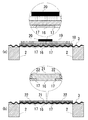
続いて、上記のコート作業で形成した感光性乳剤の層13に対してフォトマスクを用いてパターン形成を行う。なお、フォトマスクの形成については後述する。図5(a)に示すように、第1のスクリーン層4のパターン孔となるパターンが形成された第1のフォトマスク14を感光性乳剤の層13の上の指定位置に合わせて固定する。
3. Exposure work (first layer)
Subsequently, a pattern is formed on the
第1のフォトマスク14は、光線が透過しないフォトマスクパターン部15を有している。感光性乳剤の層13のフォトマスクパターン部15に対応する位置が、第1のスクリーン層5のパターン孔8となる。また、第1のフォトマスク14のフォトマスクパターン部15以外の領域は光線を透過する部分である。なお、ここでいう光線とは、紫外線及び可視光を含むものを意味するものである。
The
図5(a)で見て上部側から露光機(図示せず)で第1のフォトマスク14に光線を照射する。図5(b)で示すように、フォトマスクパターン部15では光線が透過せず、その下方に位置する感光性乳剤には光線が照射されず、そのまま未硬化領域16となる。
As seen in FIG. 5A, the
一方、それ以外の領域では光線が第1のフォトマスク14を透過し、感光性乳剤の層13に光線が照射される。図5(b)に示すように、光線が照射された感光性乳剤は硬化して硬化領域17となる。
On the other hand, in other areas, the light beam passes through the
後述する現像作業の工程にて、未硬化領域16を水で洗浄して洗い流すと同部分に貫通孔が形成され、上述したパターン孔8となる。また、硬化領域17はそのまま層を構成する部分となる。
When the
4.コート作業(2層目)
上述したコート作業と同様に、光線を照射した感光性乳剤の層13に重ねて、第2のスクリーン層5となる感光性乳剤の層18をコート作業にて形成する。ここで使用する感光性乳剤は、感光性乳剤の層13の形成に使用したものと同一の乳剤でもよいし、異なる乳剤を用いてもよい。2層目のコート作業においても感光性乳剤の層をユーザーが指定する乳剤膜厚となるように形成する。
4). Court work (2nd layer)
Similar to the above-described coating operation, a
本コート作業では、図6(a)及び図6(b)に示すようにシート状の感光性乳剤を貼り付けて層の形成を行っている。ここでは、垂直にした光線照射後の感光性乳剤の層13に対して液状の感光性乳剤を塗り、スクリーンメッシュ3の下方から感光性乳剤のフィルムシート19を貼り付ける。
In this coating operation, as shown in FIGS. 6A and 6B, a sheet-like photosensitive emulsion is pasted to form a layer. Here, a liquid photosensitive emulsion is applied to the
フィルムシート19の貼り付けは、図6(a)の矢印Yで示す方向に下方から上方へと行う。本工程でも一定の膜厚に形成したフィルムシート19を用いることで、膜厚のばらつきを低減可能となる。シートの貼り付けにより感光性乳剤の層18が形成される。
The
ここで、必ずしも、感光性乳剤の層18を、シート状の感光性乳剤を貼り付けて形成する必要はなく、例えば、上述したような塗布工程で形成する方法も採用しうる。しかしながら、第2のスクリーン層5の膜厚のばらつきを低減できる点から、シート状の感光性乳剤を貼り付けて形成することが好ましい。第2のスクリーン層5の膜厚を均一に揃えることで、被印刷物上に転写された印刷ペーストと干渉しにくくなり、より印刷の精度を高めることが可能となる。
Here, it is not always necessary to form the
5.露光作業(2層目)
続いて、上記のコート作業で形成した感光性乳剤の層18に対してフォトマスクを用いてパターン形成を行う。図7(a)に示すように、第2のスクリーン層5のパターン孔となるパターンが形成された第2のフォトマスク19を感光性乳剤の層18の上の指定位置に合わせて固定する。
5). Exposure work (2nd layer)
Subsequently, a pattern is formed on the
第2のフォトマスク19は、光線が透過しないフォトマスクパターン部20を有している。感光性乳剤の層18のフォトマスクパターン部20に対応する位置が、第2のスクリーン層5のパターン孔9となる。また、第2のフォトマスク19のフォトマスクパターン部20以外の領域は光線を透過する部分である。
The
また、第2のフォトマスク19のフォトマスクパターン部20は、第1のフォトマスクパターン14のフォトマスクパターン部15とほぼ同一の位置にパターンが形成されている。また、フォトマスクパターン部20の大きさは、フォトマスクパターン部15の大きさよりもやや大きく形成されている。
Further, the pattern of the
即ち、第2のフォトマスク19を使用して形成される第2のスクリーン層5のパターン孔9は、第1のスクリーン層4のパターン孔8と位置がほぼ一致して重なり、かつ、パターン孔9がパターン孔8よりもやや大きく形成されるものとなる。2つの孔のずれは20μm以上となることが好ましい。
That is, the
図7(a)で見て上部側から露光機(図示せず)で第2のフォトマスク19に光線を照射する。図7(b)で示すように、フォトマスクパターン部20では光線が透過せず、その下方に位置する感光性乳剤には光線が照射されず、そのまま未硬化領域21となる。
As shown in FIG. 7A, the
一方、それ以外の領域では光線が第2のフォトマスク19を透過し、感光性乳剤の層18に光線が照射される。光線が照射された感光性乳剤は硬化して硬化領域22となる。
On the other hand, in other areas, the light beam passes through the
6.現像作業
光線の照射後に、未硬化領域16及び未硬化領域21を水で洗浄して洗い流すと同部分に貫通孔が形成され、パターン孔8及びパターン孔9となる。また、硬化領域17及び硬化領域22はそのまま層を構成する部分となる。
6). Development work After the irradiation of the light beam, the
洗浄作業を経て未硬化領域が除去されこれを乾燥させると第1のスクリーン層4及び第2のスクリーン層5となる。即ち、洗浄作業を経て乾燥させるとスクリーンマスク1が完成するものとなる。
When the uncured area is removed through the cleaning operation and dried, the
7.フォトマスクの製造について
上記のスクリーンマスク1の製造に用いたフォトマスクの製造について説明する。第1のフォトマスク14及び第2のフォトマスク19は、ガラスやポリエチレンテレフタレート(PET)フィルム等の光透過性の素材で形成されている。CAD作業で所望のパターンデータを作製し、CAM作業にてガラス等の素材上に描画機を使用してパターンを形成する。本作業により、パターン孔8やパターン孔9を形成可能なフォトマスクが作成される。
7). Production of Photomask Production of the photomask used for producing the screen mask 1 will be described. The
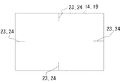
また、本発明を適用したスクリーンマスクの製造方法では、パターン孔用のパターン以外に、位置合わせ用の線を設けることができる。図8に示すように、第1のフォトマスク14には描画機により、位置決め用の線23が平板状のフォトマスクの4辺にそれぞれ設けられている。第2のフォトマスク19にも同一箇所に位置決め用の線24が形成される。
Further, in the method for manufacturing a screen mask to which the present invention is applied, alignment lines can be provided in addition to the pattern for pattern holes. As shown in FIG. 8, the
位置決め用の線23及び位置決め用の線24は、光線照射後の感光性乳剤の層13と
感光性乳剤の層18の上に第2のフォトマスク19を重ねる際の目印となる部分である。
The positioning line 23 and the positioning line 24 are portions that serve as marks when the
第1のフォトマスク14を介して露光作業を行うと、感光性乳剤の層13には位置決め用の線23に対応した線が形成される。この線は感光性乳剤の層18を介しても目視可能である。この線と、第2のフォトマスク19の位置決め用の線24を重ね合わせることで、第1のフォトマスク14のパターンと、第2のフォトマスクのパターンとの間のずれを小さなものとすることができる。
When an exposure operation is performed through the
即ち、パターン孔8とパターン孔9とが重なる位置をほぼ同じ位置とすることができる。このように、フォトマスクに位置決め用の線を形成することで、2つのスクリーン層に形成されるパターン孔の位置を合わせやすいものとなる。
That is, the position where the
ここで、重ね合わせを容易にするための目印が位置決め用の線である必要はない。重ね合わせの目印となれば充分であり、例えば丸等の記号であってもよい。但し、ずれを生じにくくなる点から、目印を設ける場合には線を形成することが好ましい。 Here, the mark for facilitating superposition does not have to be a positioning line. It is sufficient if it becomes a mark for superposition, and may be a symbol such as a circle. However, it is preferable to form a line when providing a mark because it is difficult to cause a shift.
以上の工程で完成したスクリーンマスク1は、スクリーン印刷に用いられる。印刷時には、スクリーンマスク1の第2のスクリーン層5を被印刷物6の表面に対向させて配置する。そして、スクリーンメッシュ3の側から高粘度の印刷ペーストを載せ、スクリーンメッシュ3の側からスキージを被印刷物6の側に圧力をかけて押し付けながら、スクリーンマスク1に対してスライド移動させる。
The screen mask 1 completed through the above steps is used for screen printing. At the time of printing, the
スキージによりスクリーンマスク1の第2のスクリーン層5が被印刷物に当接して離れることで印刷ペーストがパターン孔8及びパターン孔9を透過して、被印刷物上に印刷ペーストが転写される。スクリーンマスク1の端から端へとスキージがスライド移動することで、パターン孔8及びパターン孔9に応じた印刷がなされるものとなる。
When the
印刷時には、異物10や被印刷物自体の凸部がスクリーンマスク1に接触するが、その接触は第2のスクリーン層5に対して生じ、第1のスクリーン層4やスクリーンメッシュ3に対しては接触しにくいものとなっている。そのため、第1のスクリーン層4やスクリーンメッシュ3に対しての損傷が少なく、スクリーンマスク1を耐久性の高いものとすることができる。
At the time of printing, the
また、上述した製造方法では、従来のスクリーンマスク1の製造設備をそのまま使用することができるため、非常に簡易に耐久性に優れたスクリーンマスク1を製造することができるものとなっている。 Moreover, in the manufacturing method mentioned above, since the manufacturing equipment of the conventional screen mask 1 can be used as it is, the screen mask 1 excellent in durability can be manufactured very easily.
以上のように、本発明のパネルバルブの配管構造は、より簡易な配管構造を実現可能なものとなっている。
また、本発明のパネルバルブの制御方法は、より簡易な配管構造を利用する制御方法となっている。
As described above, the piping structure of the panel valve of the present invention can realize a simpler piping structure.
The panel valve control method of the present invention is a control method that uses a simpler piping structure.
1 スクリーンマスク
2 フレーム
3 スクリーンメッシュ
4 第1のスクリーン層
5 第2のスクリーン層
6 被印刷物
7 印刷ペースト
8 パターン孔
9 パターン孔
10 異物
11 スクリーンマスク
12 第2のスクリーン層
13 感光性乳剤の層
14 第1のフォトマスク
15 フォトマスクパターン部
16 未硬化領域
17 硬化領域
18 感光性乳剤の層
19 フィルムシート
20 フォトマスクパターン部
21 未硬化領域
22 硬化領域
23 位置決め用の線
24 位置決め用の線
25 フィルムシート
26 液状の感光性乳剤
DESCRIPTION OF SYMBOLS 1
Claims (11)
該枠体内に張設されたスクリーンメッシュと、
該スクリーンメッシュに設けられ、第1のパターン孔が形成された第1のパターン層と、
該第1のパターン層の前記枠体とは反対側の面に設けられると共に、前記第1のパターン孔と対応する位置に第2のパターン孔が形成された第2のパターン層とを備える
スクリーンマスク。 A frame,
A screen mesh stretched in the frame;
A first pattern layer provided on the screen mesh and having a first pattern hole formed thereon;
A screen provided with a second pattern layer provided on a surface opposite to the frame of the first pattern layer and having a second pattern hole formed at a position corresponding to the first pattern hole; mask.
請求項1に記載のスクリーンマスク。 The screen mask according to claim 1, wherein a hole diameter of the second pattern hole is formed larger than a hole diameter of the first pattern hole.
請求項2に記載のスクリーンマスク。 The screen mask according to claim 2, wherein a distance between an outer peripheral surface of the second pattern hole and an outer peripheral surface of the first pattern hole is 20 μm or more.
請求項1、請求項2または請求項3に記載のスクリーンマスク。 The screen mask according to claim 1, wherein the first pattern layer is provided with positioning lines on an outer peripheral portion.
該枠体内に張設されたスクリーンメッシュと、
該スクリーンメッシュに設けられ、その中央領域に第1のパターン孔が形成された第1のパターン層と、
該第1のパターン層の前記枠体とは反対側の面かつ前記第1のパターン孔よりも外側の領域に設けられた第2のパターン層とを備える
スクリーンマスク。 A frame,
A screen mesh stretched in the frame;
A first pattern layer provided in the screen mesh and having a first pattern hole formed in a central region thereof;
A screen mask comprising: a second pattern layer provided on a surface of the first pattern layer opposite to the frame and on a region outside the first pattern hole.
前記スクリーンメッシュに第1のパターン層となる感光性乳剤の層を設ける第2の工程と、
該第2の工程で設けた感光性乳剤の層に、第1のフォトマスクを重ねて光線を照射し、第1のパターン孔が形成された第1のパターン層とする第3の工程と、
前記第1のパターン層に第2のパターン層となる感光性乳剤の層を設ける第4の工程と、
該第4の工程で設けた感光性乳剤の層に、第2のフォトマスクを重ねて光線を照射し、前記第1のパターン孔に対応する第2のパターン孔が形成された第2のパターン層とする第5の工程とを備える
スクリーンマスクの製造方法。 A first step of fixing the screen mesh in the frame;
A second step of providing a photosensitive emulsion layer as a first pattern layer on the screen mesh;
A third step in which a first photomask is superimposed on the layer of the photosensitive emulsion provided in the second step and irradiated with light to form a first pattern layer having a first pattern hole;
A fourth step of providing a photosensitive emulsion layer as a second pattern layer on the first pattern layer;
A second pattern in which a second photomask is superimposed on the layer of the photosensitive emulsion provided in the fourth step and irradiated with light to form a second pattern hole corresponding to the first pattern hole. A method for producing a screen mask, comprising: a fifth step of forming a layer.
請求項6に記載のスクリーンマスクの製造方法。 The method for manufacturing a screen mask according to claim 6, wherein a hole diameter of the second pattern hole is formed larger than a hole diameter of the first pattern hole.
請求項6または請求項7に記載のスクリーンマスクの製造方法。 The method for manufacturing a screen mask according to claim 6 or 7, wherein the second step is to paste a sheet-like photosensitive emulsion on the screen mesh.
請求項6、請求項7または請求項8に記載のスクリーンマスクの製造方法。 9. The method of manufacturing a screen mask according to claim 6, wherein in the fourth step, a sheet-like photosensitive emulsion is pasted on the first pattern layer. 10.
前記第3の工程は、前記第1のパターン層に前記第1のフォトマスクの位置決め用の線に対応した第1のパターン線を形成し、
前記第5の工程は、前記第1のパターン線と前記第2のフォトマスクの位置決め用の線を合わせて同第2のフォトマスクを重ねる
請求項6、請求項7、請求項8または請求項9に記載のスクリーンマスクの製造方法。 The first photomask and the second photomask are provided with positioning lines,
The third step forms a first pattern line corresponding to a positioning line for the first photomask on the first pattern layer,
The fifth step includes overlapping the second photomask by aligning the first pattern line and the positioning line for the second photomask. 10. A method for producing a screen mask according to 9.
該枠体の内側に張設されたスクリーンメッシュと、
該スクリーンメッシュに設けられ、パターン孔が形成されると共に、パターン孔の非形成領域の厚みがパターン孔の形成領域周辺の厚みよりも大きく形成されたパターン層とを備える
スクリーンマスク。 A frame,
A screen mesh stretched inside the frame;
A screen mask comprising: a pattern layer provided on the screen mesh, in which pattern holes are formed, and a thickness of a non-pattern hole forming region is larger than a thickness around a pattern hole forming region.
Priority Applications (1)
| Application Number | Priority Date | Filing Date | Title |
|---|---|---|---|
| JP2015235719A JP2017100367A (en) | 2015-12-02 | 2015-12-02 | Screen mask and method for producing screen mask |
Applications Claiming Priority (1)
| Application Number | Priority Date | Filing Date | Title |
|---|---|---|---|
| JP2015235719A JP2017100367A (en) | 2015-12-02 | 2015-12-02 | Screen mask and method for producing screen mask |
Publications (1)
| Publication Number | Publication Date |
|---|---|
| JP2017100367A true JP2017100367A (en) | 2017-06-08 |
Family
ID=59015831
Family Applications (1)
| Application Number | Title | Priority Date | Filing Date |
|---|---|---|---|
| JP2015235719A Pending JP2017100367A (en) | 2015-12-02 | 2015-12-02 | Screen mask and method for producing screen mask |
Country Status (1)
| Country | Link |
|---|---|
| JP (1) | JP2017100367A (en) |
Cited By (5)
| Publication number | Priority date | Publication date | Assignee | Title |
|---|---|---|---|---|
| CN111142330A (en) * | 2020-01-21 | 2020-05-12 | 冷水江市京科电子科技有限公司 | Screen printing plate processing method for preventing screen penetration |
| JP2020179640A (en) * | 2019-04-26 | 2020-11-05 | マクセルホールディングス株式会社 | Screen printing mask |
| WO2020241370A1 (en) * | 2019-05-27 | 2020-12-03 | 株式会社 ムラカミ | Screen printing plate and method for manufacturing same |
| JP2021172046A (en) * | 2020-04-28 | 2021-11-01 | ミタニマイクロニクス株式会社 | Screen mask, production method of screen mask and printed matter production method |
| CN114714750A (en) * | 2022-03-23 | 2022-07-08 | 上饶捷泰新能源科技有限公司 | Manufacturing method of screen printing plate for printing positive electrode of solar cell and screen printing plate |
Citations (8)
| Publication number | Priority date | Publication date | Assignee | Title |
|---|---|---|---|---|
| JPS60263155A (en) * | 1984-06-12 | 1985-12-26 | Sono Kogyo Kk | Special screen engraging method and spherical surface printing method |
| JPS6354289A (en) * | 1986-08-25 | 1988-03-08 | Kashiwagi Kogei:Kk | Printing screen and production thereof |
| JPH06143855A (en) * | 1992-11-06 | 1994-05-24 | Matsushita Electric Ind Co Ltd | Screen printing plate and production thereof |
| DE10108120A1 (en) * | 2001-02-21 | 2002-02-28 | Rastal Gmbh & Co Kg | Screen printing relief layer, e.g. on glass substrate uses screen with thick photoresist on side towards substrate on woven fabric of specified fineness |
| JP2006327122A (en) * | 2005-05-30 | 2006-12-07 | Fuchigami Micro:Kk | Screen printing plate and method for manufacturing screen printing plate |
| US20100139561A1 (en) * | 2008-12-10 | 2010-06-10 | Bloom Terry R | Counter sunk screen |
| JP2013086315A (en) * | 2011-10-15 | 2013-05-13 | Tokai Seiki Kk | Screen plate for screen printer |
| JP2015064454A (en) * | 2013-09-24 | 2015-04-09 | 株式会社村田製作所 | Method for manufacturing screen printing plate |
-
2015
- 2015-12-02 JP JP2015235719A patent/JP2017100367A/en active Pending
Patent Citations (8)
| Publication number | Priority date | Publication date | Assignee | Title |
|---|---|---|---|---|
| JPS60263155A (en) * | 1984-06-12 | 1985-12-26 | Sono Kogyo Kk | Special screen engraging method and spherical surface printing method |
| JPS6354289A (en) * | 1986-08-25 | 1988-03-08 | Kashiwagi Kogei:Kk | Printing screen and production thereof |
| JPH06143855A (en) * | 1992-11-06 | 1994-05-24 | Matsushita Electric Ind Co Ltd | Screen printing plate and production thereof |
| DE10108120A1 (en) * | 2001-02-21 | 2002-02-28 | Rastal Gmbh & Co Kg | Screen printing relief layer, e.g. on glass substrate uses screen with thick photoresist on side towards substrate on woven fabric of specified fineness |
| JP2006327122A (en) * | 2005-05-30 | 2006-12-07 | Fuchigami Micro:Kk | Screen printing plate and method for manufacturing screen printing plate |
| US20100139561A1 (en) * | 2008-12-10 | 2010-06-10 | Bloom Terry R | Counter sunk screen |
| JP2013086315A (en) * | 2011-10-15 | 2013-05-13 | Tokai Seiki Kk | Screen plate for screen printer |
| JP2015064454A (en) * | 2013-09-24 | 2015-04-09 | 株式会社村田製作所 | Method for manufacturing screen printing plate |
Cited By (9)
| Publication number | Priority date | Publication date | Assignee | Title |
|---|---|---|---|---|
| JP2020179640A (en) * | 2019-04-26 | 2020-11-05 | マクセルホールディングス株式会社 | Screen printing mask |
| JP7329359B2 (en) | 2019-04-26 | 2023-08-18 | マクセル株式会社 | screen printing mask |
| WO2020241370A1 (en) * | 2019-05-27 | 2020-12-03 | 株式会社 ムラカミ | Screen printing plate and method for manufacturing same |
| CN111142330A (en) * | 2020-01-21 | 2020-05-12 | 冷水江市京科电子科技有限公司 | Screen printing plate processing method for preventing screen penetration |
| CN111142330B (en) * | 2020-01-21 | 2023-04-07 | 冷水江市京科电子科技有限公司 | Screen printing plate processing method for preventing screen penetration |
| JP2021172046A (en) * | 2020-04-28 | 2021-11-01 | ミタニマイクロニクス株式会社 | Screen mask, production method of screen mask and printed matter production method |
| JP7335614B2 (en) | 2020-04-28 | 2023-08-30 | ミタニマイクロニクス株式会社 | Screen mask, screen mask manufacturing method, and printed matter manufacturing method |
| CN114714750A (en) * | 2022-03-23 | 2022-07-08 | 上饶捷泰新能源科技有限公司 | Manufacturing method of screen printing plate for printing positive electrode of solar cell and screen printing plate |
| CN114714750B (en) * | 2022-03-23 | 2024-03-26 | 上饶捷泰新能源科技有限公司 | Method for manufacturing screen printing plate for printing positive electrode of solar cell and screen printing plate |
Similar Documents
| Publication | Publication Date | Title |
|---|---|---|
| JP2017100367A (en) | Screen mask and method for producing screen mask | |
| JP2005338806A (en) | Method for fabricating cliche and method for forming pattern using the same | |
| CN102371748B (en) | Roll mold, method for fabricating the same and method for fabricating thin film pattern using the same | |
| JP6418891B2 (en) | Screen mask and method for manufacturing screen mask | |
| JP2023138827A (en) | Screen mask, production method of screen mask and printed matter production method | |
| US20140373742A1 (en) | Method of manufacturing a high-resolution flexographic printing plate | |
| CN102211441A (en) | Roll mold, method for fabricating the same and method for fabricating thin film pattern using the same | |
| JP2015204399A (en) | Mold, imprint device, imprint method, and manufacturing method of article | |
| CN107710072B (en) | Photomask, laminated body including photomask, photomask manufacturing method, patterning device, and patterning method | |
| JP3983278B2 (en) | Exposure method and exposure apparatus | |
| JP5891861B2 (en) | Reverse printing method and reverse printing apparatus | |
| JP2015169803A (en) | Mask and pattern forming method | |
| JP2005148531A (en) | Aligner for printed-circuit board corresponding to expansion and contraction thereof | |
| CN101435990A (en) | Mask plate and manufacturing method thereof | |
| JPH04239684A (en) | Method for forming of fine pattern | |
| JP6410651B2 (en) | Method for measuring strain of pattern formed on printing plate cylinder | |
| JP4250448B2 (en) | Double-sided exposure method | |
| TWI444759B (en) | Mask, exposing method and exposure device | |
| JP6402059B2 (en) | Method and apparatus for producing printing plate cylinder | |
| CN101661218A (en) | Method for preparing transparent light mask | |
| JP6358488B2 (en) | Method for producing offset printing cliché and offset printing cliché | |
| JP2019084697A (en) | Screen mask, method for producing screen mask, screen printer, method for producing printed matter, and exposure device | |
| KR102415094B1 (en) | Exposure apparatus and method for nanoimprint process for non-planar substrates | |
| KR101598340B1 (en) | Roll to roll printing and etching system | |
| JP2009148901A (en) | Highly precise relief printing plate |
Legal Events
| Date | Code | Title | Description |
|---|---|---|---|
| A621 | Written request for application examination |
Free format text: JAPANESE INTERMEDIATE CODE: A621 Effective date: 20180910 |
|
| A131 | Notification of reasons for refusal |
Free format text: JAPANESE INTERMEDIATE CODE: A131 Effective date: 20190625 |
|
| A977 | Report on retrieval |
Free format text: JAPANESE INTERMEDIATE CODE: A971007 Effective date: 20190626 |
|
| A02 | Decision of refusal |
Free format text: JAPANESE INTERMEDIATE CODE: A02 Effective date: 20191218 |