JP2017020406A - Control device for internal combustion engine - Google Patents
Control device for internal combustion engine Download PDFInfo
- Publication number
- JP2017020406A JP2017020406A JP2015138202A JP2015138202A JP2017020406A JP 2017020406 A JP2017020406 A JP 2017020406A JP 2015138202 A JP2015138202 A JP 2015138202A JP 2015138202 A JP2015138202 A JP 2015138202A JP 2017020406 A JP2017020406 A JP 2017020406A
- Authority
- JP
- Japan
- Prior art keywords
- intake air
- humidity
- internal combustion
- combustion engine
- air temperature
- Prior art date
- Legal status (The legal status is an assumption and is not a legal conclusion. Google has not performed a legal analysis and makes no representation as to the accuracy of the status listed.)
- Pending
Links
Images


Abstract
Description
本発明は内燃機関を制御する内燃機関用制御装置に係り、特に内燃機関に吸入される空気の湿度に応じて点火時期等の制御目標値を演算する内燃機関用制御装置に関するものである。 The present invention relates to an internal combustion engine control apparatus that controls an internal combustion engine, and more particularly to an internal combustion engine control apparatus that calculates a control target value such as an ignition timing in accordance with the humidity of air sucked into the internal combustion engine.
近年、自動車等の車両の燃費や排気の規制が強化されつつあり、この規制は今後も益々強くなる傾向にある。特に燃費については、近年のガソリン価格の高騰、地球温暖化への影響、エネルギー資源枯渇問題などにより、極めて関心が高くなっている。このような状況下において、車両の燃費向上を目的とした様々な技術開発が行なわれており、例えば、圧縮比の向上、外部EGRの大量導入、ストイキ燃焼領域の拡大等が行われている。 In recent years, regulations on fuel consumption and exhaust of vehicles such as automobiles are being strengthened, and these regulations tend to become stronger in the future. In particular, fuel consumption has become extremely interested due to the recent rise in gasoline prices, the impact on global warming, and the problem of exhaustion of energy resources. Under such circumstances, various technical developments for the purpose of improving the fuel efficiency of vehicles have been carried out. For example, improvement of the compression ratio, introduction of a large amount of external EGR, expansion of the stoichiometric combustion region, etc. have been carried out.
そして、これらの技術においては燃焼の適正化が重要であり、点火時期を適切に制御する必要がある。内燃機関の燃焼においては、最も燃費が良くなる点火時期(以下、MBT点火時期)が存在し、そのMBT点火時期に少しでも近づけるように制御している。例えば、外部EGRを燃焼室内に導入すると、燃焼速度が低下して出力が低下するため点火時期を進角側に補正制御する必要があり、外部EGRの排気ガスの量に応じて点火時期を補正している。 In these technologies, it is important to optimize combustion, and it is necessary to appropriately control the ignition timing. In the combustion of an internal combustion engine, there is an ignition timing (hereinafter referred to as MBT ignition timing) at which the fuel efficiency is the best, and control is performed so as to approach the MBT ignition timing as much as possible. For example, when external EGR is introduced into the combustion chamber, the combustion speed decreases and the output decreases. Therefore, it is necessary to correct and control the ignition timing to the advance side. The ignition timing is corrected according to the amount of exhaust gas from the external EGR. doing.
更に、最近では燃費向上のため、点火時期への高精度化の要求がより一層高くなっており、吸入空気の湿度に応じて点火時期を補正する方法も検討されている。湿度はEGRガスと同様、燃焼を阻害する要因となるため、湿度が高い場合は点火時期を進角側に補正し、逆に湿度が低い場合は点火時期を遅角側に補正するようにしている。このように湿度に応じて点火時期を補正する方法として、例えば、特開平9−68146号公報(特許文献1)が知られている。 Furthermore, recently, in order to improve fuel efficiency, the demand for higher accuracy in the ignition timing has been further increased, and a method for correcting the ignition timing in accordance with the humidity of the intake air has been studied. Humidity, like EGR gas, is a factor that inhibits combustion. If the humidity is high, the ignition timing is corrected to the advance side. Conversely, if the humidity is low, the ignition timing is corrected to the retard side. Yes. As a method for correcting the ignition timing in accordance with the humidity as described above, for example, Japanese Patent Laid-Open No. 9-68146 (Patent Document 1) is known.
特許文献1においては、回転数と負荷とからなる基本点火時期をマップデータとして記憶し、検出された湿度から点火時期の補正量を演算し、回転数、負荷、温度の少なくとも1つに応じて補正量を反映させる反映率を演算し、基本点火時期、補正量、反映率とから最終的な点火時期を決定ことが記載されている。この方法によれば、検出した湿度から点火時期の補正が可能になる。
In
そして、特許文献1に記載されているような湿度情報に基づいた点火時期の補正制御は、湿度センサが故障して異常値が出力されると正しい点火時期補正が行えなくなり、ノッキングや失火が発生して内燃機関の破損やエンストにつながるおそれがある。特許文献1には、この湿度センサの異常に対応する技術については何ら開示するところはない。
The ignition timing correction control based on the humidity information as described in
尚、排気系に湿度センサを設け、この湿度センサの異常を検出する方法として、例えば、特開2003−172192号公報(特許文献2)が知られている。 As a method of providing a humidity sensor in the exhaust system and detecting an abnormality of the humidity sensor, for example, Japanese Patent Laid-Open No. 2003-172192 (Patent Document 2) is known.
特許文献2においては、内燃機関の排気系のHC吸着材の近傍に設けた湿度センサの故障の有無を検知することを目的としている。そして、内燃機関の運転停止後に湿度センサによる湿度の検出値がほぼ一定となる状態において、その検出値に基づき湿度センサの故障の有無を検知している。故障の有無の検知は、湿度の検出値が、HC吸着材の近傍の温度状態に応じて設定した所定の上限側閾値及び下限側閾値の間の範囲内に存在するか否かを判断することにより行うものである。
In
ところで、内燃機関の点火時期のような制御目標値を湿度の大きさによって補正する場合は、内燃機関が駆動されている状態で湿度を測定し、測定された湿度に対応して制御目標値を補正する必要がある。このため、内燃機関が駆動されている状態で湿度センサの故障、或いは異常を検出する必要がある。尚、以下では故障及び異常をまとめて故障と表記する。 By the way, when the control target value such as the ignition timing of the internal combustion engine is corrected by the magnitude of the humidity, the humidity is measured while the internal combustion engine is driven, and the control target value is set corresponding to the measured humidity. It is necessary to correct. For this reason, it is necessary to detect a failure or abnormality of the humidity sensor while the internal combustion engine is being driven. In the following, failures and abnormalities are collectively referred to as failures.
これに対して、特許文献2では、内燃機関の停止後の湿度センサ故障を判定するものであり、内燃機関が動作している場合については述べられていない。また、特許文献2の目的は、排ガス中の炭化水素(HC)を吸着するためのHC吸着材の劣化を正しく評価するものであり、点火時期制御など内燃機関の制御目標値による制御の動作保証のための診断ではない。
On the other hand,
本発明の目的は、内燃機関の制御目標値を補正するために使用されている湿度センサの故障を、内燃機関が駆動されている状態で精度よく検出することができる新規な内燃機関用制御装置を提供することにある。 An object of the present invention is to provide a novel control device for an internal combustion engine that can accurately detect a failure of a humidity sensor used to correct a control target value of the internal combustion engine while the internal combustion engine is being driven. Is to provide.
本発明の第1の特徴は、吸気管内の相対湿度を測定する吸気湿度測定手段と、吸気温度を測定する吸気温度測定手段を備え、吸気湿度と吸気温度の相関関係に基づき、吸気温度が上昇したときに相対湿度が上昇した場合、或いは吸気温度が低下したときに相対湿度が低下した場合に吸気湿度測定手段が故障していると判定する、ところにある。 The first feature of the present invention includes an intake humidity measuring means for measuring the relative humidity in the intake pipe and an intake air temperature measuring means for measuring the intake air temperature, and the intake air temperature rises based on the correlation between the intake air humidity and the intake air temperature. If the relative humidity increases when the intake air temperature decreases, or if the relative humidity decreases when the intake air temperature decreases, it is determined that the intake humidity measuring means has failed.
本発明の第2の特徴は、吸気管内の相対湿度を測定する吸気湿度測定手段と、吸気温度を測定する吸気温度測定手段を備え、吸気湿度測定手段の出力が所定の上限値、或いは下限値、或いは上下限値に張り付いた時に吸気湿度測定手段が故障していると判定する、ところにある。 The second feature of the present invention includes an intake humidity measuring means for measuring the relative humidity in the intake pipe and an intake air temperature measuring means for measuring the intake air temperature, and the output of the intake humidity measuring means has a predetermined upper limit value or lower limit value. Alternatively, when the upper and lower limit values are stuck, it is determined that the intake humidity measuring means is out of order.
本発明によれば、内燃機関が駆動されている状態で吸気湿度測定手段の故障診断が可能となるため、正常に機能している吸気湿度測定手段の測定値に基づいて正確な制御目標値を求めることができる。 According to the present invention, since the failure diagnosis of the intake humidity measuring means can be performed while the internal combustion engine is being driven, an accurate control target value can be obtained based on the measured value of the normally functioning intake humidity measuring means. Can be sought.
本発明の実施形態について図面を用いて詳細に説明するが、本発明は以下の実施形態に限定されることなく、本発明の技術的な概念の中で種々の変形例や応用例をもその範囲に含むものである。 Embodiments of the present invention will be described in detail with reference to the drawings. However, the present invention is not limited to the following embodiments, and various modifications and application examples are included in the technical concept of the present invention. It is included in the range.
図1は、本発明が適用される内燃機関用制御装置が搭載された内燃機関システムを示したものである。内燃機関システム10は、例えば4つの気筒を備えた火花点火式の多気筒エンジンであって、シリンダヘッド11a及びシリンダブロック11bからなるシリンダ11と、このシリンダ11の各気筒内に摺動自在に嵌挿されたピストン12とを備え、ピストン12は、コンロッド13を介してクランク軸(図示せず)に連結されている。また、ピストン12の上方には、所定形状の天井部を有する燃焼室14が画成され、各気筒の燃焼室14には、点火コイル15から高電圧化された点火信号が供給される点火プラグ16が設けられている。
FIG. 1 shows an internal combustion engine system equipped with a control device for an internal combustion engine to which the present invention is applied. The internal
また、燃焼室14は、エアクリーナ17、スロットルバルブ18、コレクター19、吸気マニホールド20、吸気ポート21等を備えた吸気通路22と連通しており、燃料の燃焼に必要な空気は、この吸気通路22を通り、吸気通路22の下流端である吸気ポート21の端部に配置された吸気カム軸23により開閉駆動される吸気バルブ24を介して、各気筒の燃焼室14に吸入されるようになっている。また、吸気通路22の吸気マニホールド20には、吸気ポート21へ向けて燃料を噴射する燃料噴射弁25が気筒毎に設けられている。
The
また、吸気通路22のエアクリーナ17の下流には、吸入空気の流量を検出するエアフローセンサ26が配設されている。このエアフローセンサ26は、吸入空気量(質量流量)が大きくなるに従って、測定対象となる吸入空気流に配置されたホットワイヤ(発熱抵抗体)に流れる電流値が増加し、吸入空気量が小さくなるに従ってホットワイヤに流れる電流値が減少するようにブリッジ回路が構成されている。そして、エアフローセンサ26のホットワイヤに流れる発熱抵抗電流値は電圧信号として抽出されて、ECU(エンジンコントロールユニット)27へ送信されるようになっている。
An
吸気通路22を介して吸入された空気と燃料噴射弁25から噴射された燃料との混合気は、吸気バルブ24を介して燃焼室14へ吸入され、点火コイル15に接続された点火プラグ16よる火花点火によって燃焼される。そして、燃焼室14での燃焼後の排気ガスは、排気カム軸28により開閉駆動される排気バルブ29を介して燃焼室14から排気され、排気ポートや排気マニホールド、排気管等(不図示)を備えた排気通路30を通って外部の大気中へ排出されるようになっている。
A mixture of the air sucked through the
排気通路30には、アルミナやセリアなどの担体に白金やパラジウムなどを塗布した排気ガス浄化用の三元触媒31が配設されており、この三元触媒31の上流側には、触媒前空燃比に対して線形の出力特性を有するリニア空燃比センサ32が配設され、三元触媒31の下流側には、触媒後空燃比がストイキ(理論空燃比)よりもリッチ側かリーン側かを識別するためのスイッチング信号を出力するO2センサ33が配設されている。
The
また、エンジン10の各気筒に対して配備された燃料噴射弁25は、燃料タンク34と接続されており、燃料タンク34の内部の燃料は、燃料ポンプ35や燃圧レギュレータ36等を備えた燃料供給機構により所定燃圧に調圧されて燃料噴射弁25に供給されるようになっている。所定燃圧の燃料が供給された燃料噴射弁25は、ECU27から供給されるエンジン負荷等の運転状態に応じたデューティ(パルス幅:開弁時間に相当する)を有する燃料噴射パルス信号によって開弁駆動され、その開弁時間に応じた量の燃料を吸気ポート21に向けて噴射するようになっている。
A
尚、ECU27は種々の制御目標値を演算するものであり、例えば燃料噴射弁25による燃料噴射制御(空燃比制御)、点火プラグ16による点火時期制御等を行なうためのマイクロコンピュータを内蔵している。
The
そして、このECU27は、内燃機関の少なくとも1つ以上の制御目標値を演算する機能を有すると共に、制御目標値の少なくとも1つの制御目標値を相対湿度の大きさによって補正する機能を有する制御機能部を備えている。そして、この制御機能部は、後述するように湿度センサの故障を検出する診断機能を備えている。
The
吸気通路20には湿度センサ37と温度センサ38が取付けられており、吸気管内を流れる吸入空気の湿度と温度を計測し、計測した湿度信号と温度信号をECU27へ送信する。ここで、湿度センサ37と温度センサ38を搭載する位置は、エアフローセンサ26よりも燃焼室14側に取り付けてもよく、また、エアフローセンサ26に湿度や温度を計測する機能を持たせてもよい。本実施例ではエアフローセンサ26とスロットルバルブ25の間に湿度センサ37と温度センサ38を搭載した例を記載している。
A
図2は、図1に示した吸気通路22付近の拡大図である。スロットルバルブ18を開けると、吸入された空気はエアクリーナ17を通過して、エアフローセンサ26、湿度センサ37、温度センサ38を通過し、スロットルバルブ18を通過して燃焼室に供給される。
FIG. 2 is an enlarged view of the vicinity of the
ここで吸入空気は、エアクリーナ17を通過するため、エアクリーナ17内の温度に影響されて通過する空気(以下、吸気と記載する場合もある)の温度が変化する。また、吸入される空気の流速は、スロットルバルブ18の開度により変化し、エアクリーナ17内を通過する時間が異なるため、吸入空気の温度変化が異なるようになる。
Here, since the intake air passes through the
例えば、スロットルバルブ18の開度が大きいときは、吸入する空気の流速が速いため、エアクリーナ17内を通過する時間が短くなり、エアクリーナ17内の温度による吸入空気の温度上昇は小さくなる。一方、スロットルバルブ18の開度が小さいときは、吸入する空気の流速が遅いため、エアクリーナ17内を通過する時間が長くなり、エアクリーナ内の温度による吸入空気の温度上昇は大きくなる。
For example, when the opening degree of the
図2に示すAは吸入空気の流速が速いときで、エアクリーナ17を通過する空気の時間tA、湿度センサ37付近での空気温度TAとした場合と、図2のBは吸入空気の流速が遅いときで、エアクリーナを通過する時間tB、湿度センサ37付近での空気温度TBとした場合では、エアクリーナ17の空気の通過時間は、tA<tBの関係であり、湿度センサ37付近での空気温度は、TA<TBの関係となる。
2A shows the case where the flow velocity of the intake air is high, the time tA of the air passing through the
つまり、スロットルバルブ18の開度により、吸入する空気の温度が変化するため、湿度センサ37や温度センサ38付近を通過する空気の温度は常に変化する。尚、通過する外部からの空気温度自体によっても空気の温度は変化する。したがって、要は温度センサ38が燃焼室14に吸入される空気の温度を検出できれば良いものである。
That is, since the temperature of the intake air changes depending on the opening degree of the
図3は、温度、絶対湿度及び相対湿度の関係を示した湿り空気線図を示している。この湿り空気線図は良く知られているものである。この湿り空気図においては、温度と相対湿度と絶対湿度についての関係性を示しており、絶対湿度が一定の場合、温度が変化すると相対湿度が変化する関係を示している。つまり外気の絶対湿度が一定である状況では吸入する空気の絶対湿度も一定であるため、図2で説明したスロットルの開度によって変化する吸入する空気の温度変化により、相対湿度が変化することがわかる。 FIG. 3 shows a wet air diagram showing the relationship between temperature, absolute humidity and relative humidity. This wet air diagram is well known. This wet air diagram shows the relationship between temperature, relative humidity, and absolute humidity. When the absolute humidity is constant, the relationship shows that the relative humidity changes as the temperature changes. That is, in the situation where the absolute humidity of the outside air is constant, the absolute humidity of the intake air is also constant. Therefore, the relative humidity may change due to the temperature change of the intake air that changes according to the throttle opening described in FIG. Recognize.
図3で温度が上昇すると相対湿度は低下し、温度が低下すると相対湿度は上昇することがわかる。相対湿度は以下の式によって表すことができる。
RH =α/T(ここで、RH:相対湿度(%)、T:温度(℃)、α:係数)
つまり、吸入空気に含まれる水分量が同じ場合(=絶対湿度が一定)においては、吸気温度と相対湿度には相関関係があるため、図4に示しているようにスロットルバルブ18の上流側に配置されている湿度センサ37と温度センサ38の出力値の相対的な関係を比較することで、湿度センサ37の故障を判定することが出来る。
In FIG. 3, it can be seen that the relative humidity decreases as the temperature increases, and the relative humidity increases as the temperature decreases. The relative humidity can be expressed by the following equation.
RH = α / T (where RH: relative humidity (%), T: temperature (° C.), α: coefficient)
In other words, when the amount of moisture contained in the intake air is the same (= the absolute humidity is constant), the intake air temperature and the relative humidity have a correlation, so that the upstream side of the
図5は、吸気温度と相対湿度の実測値のデータを示している。この図5では、吸気温度と相対湿度の相関関係はほぼ変わらずに、RH=α/Tの関係は成立する。ただ、場合によっては空気中の水分量が急激に変動するときは、急激に変動している期間においてRH=α/Tの関係が成り立たないことが生じることがある。 FIG. 5 shows measured value data of the intake air temperature and relative humidity. In FIG. 5, the correlation between the intake air temperature and the relative humidity is substantially unchanged, and the relationship of RH = α / T is established. However, in some cases, when the amount of moisture in the air changes abruptly, the relationship of RH = α / T may not be established during the period of abrupt fluctuation.
しかしながら、本実施例において取得する吸気温度や相対湿度は、図2で示した吸気通路20を想定したものであり、外気とほぼ同じ水分量を含んだ空気である。このため外気の空気中の水分量は急激に変動することはないので、湿度センサ37付近の空気中の水分量は急激に変動することはない。よってRH=α/Tの関係は成立すると考えて差し支えないものである。
However, the intake air temperature and relative humidity acquired in the present embodiment are assumed to be the
このような考え方から、図6に示しているような湿度センサの故障判定を行う制御ブロックを提案するものである。図6は、湿度センサの故障判定を行う制御ブロックを示している。吸気温度測定手段50と吸気湿度測定手段51の情報から、湿度センサ故障判定手段52が吸気湿度測定手段51の故障状態を検出するものである。 From such an idea, a control block for determining a failure of the humidity sensor as shown in FIG. 6 is proposed. FIG. 6 shows a control block for determining a failure of the humidity sensor. The humidity sensor failure determination means 52 detects the failure state of the intake humidity measurement means 51 from the information of the intake air temperature measurement means 50 and the intake humidity measurement means 51.
図6に示す制御ブロックは、マイクロコンピュータで実行される制御機能をブロックで表現した制御機能部の一部である。この制御機能部には、吸気管内に設けられた吸気湿度測定手段と吸気温度測定手段からの情報が入力され、制御機能部は、内燃機関が駆動されている状態で、吸気湿度測定手段からの相対湿度情報と吸気温度測定手段からの吸気温度情報の相関関係に基づき、吸気温度が上昇したときに相対湿度が上昇した場合、或いは吸気温度が低下したときに相対湿度が低下した場合には吸気湿度測定手段が故障していると判定する診断機能が備えられている。 The control block shown in FIG. 6 is a part of a control function unit that expresses a control function executed by the microcomputer as a block. Information from the intake air humidity measuring means and the intake air temperature measuring means provided in the intake pipe is input to the control function unit, and the control function unit receives the information from the intake humidity measurement means while the internal combustion engine is driven. Based on the correlation between the relative humidity information and the intake air temperature information from the intake air temperature measuring means, if the relative humidity rises when the intake air temperature rises, or if the relative humidity falls when the intake air temperature falls, the intake air A diagnostic function for determining that the humidity measuring means is out of order is provided.
ここで、吸気温度測定手段50は、例えば温度センサ38から温度を直接的に測定する手段や、温度センサを使用せずに他の情報から温度を推定する手段等を用いることができる。また、吸気湿度測定手段51は、故障診断対象の湿度センサ37を用いることができる。
Here, as the intake air temperature measuring means 50, for example, means for directly measuring the temperature from the
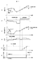
図7は図6に示す湿度センサ故障判定手段52の判定方法の一例を示している。図7では、吸気温度変化と相対湿度変化の相対関係から、湿度センサ37の故障診断を実行する例である。この図では吸気温度と相対湿度が上昇したときの例を示している。
FIG. 7 shows an example of the determination method of the humidity sensor failure determination means 52 shown in FIG. FIG. 7 shows an example in which failure diagnosis of the
吸気温度と相対湿度を一定の時間間隔(サンプリング時間t)で測定し、(a)、(b)で示すようにt時間当たりの温度の変化量ΔTを算出する。ここで、(b)にある通りΔTが診断開始閾値を超えた時に診断を実行するものである。この診断開始閾値は温度が上昇方向にある時と、下降方向にある時に設定されるものであり、図7では温度が上昇している時を示している。 The intake air temperature and the relative humidity are measured at a constant time interval (sampling time t), and a temperature change amount ΔT per t time is calculated as shown in (a) and (b). Here, as shown in (b), the diagnosis is executed when ΔT exceeds the diagnosis start threshold. This diagnosis start threshold is set when the temperature is in the increasing direction and when the temperature is in the decreasing direction, and FIG. 7 shows the time when the temperature is increasing.
同様に、(c)、(d)に示すようにt時間当たりの相対湿度の変化量ΔRHを測定し、(d)にある通りΔRHが故障判定閾値を超えた時に故障が発生したと判断するものである。したがって、ΔTが所定値(診断開始閾値)以上、かつΔRHが所定値(故障判定閾値)以上のとき、(e)に示すように湿度センサNGカウンタを「1」だけ増やすようにする。 Similarly, as shown in (c) and (d), the amount of change ΔRH in relative humidity per t time is measured, and it is determined that a failure has occurred when ΔRH exceeds the failure determination threshold as shown in (d). Is. Therefore, when ΔT is equal to or greater than a predetermined value (diagnosis start threshold) and ΔRH is equal to or greater than a predetermined value (failure determination threshold), the humidity sensor NG counter is increased by “1” as shown in (e).
そして、(f)にあるように湿度センサNGカウンタが所定回数(例えば3)以上となったとき、湿度センサの故障判定フラグを「1」にして、湿度センサ37が故障していると確定診断することができる。尚、湿度センサNGカウンタの所定回数は任意であるが、ΔRHが所定値以下に変化した時は故障判定フラグは「0」にリセットされるものである。
When the humidity sensor NG counter reaches a predetermined number of times (for example, 3) or more as shown in (f), the failure determination flag of the humidity sensor is set to “1”, and it is confirmed that the
ここで、湿度センサ37の故障診断の誤判定を防ぐために、以下の2つの誤判定の防止方法を実行している。
Here, in order to prevent erroneous determination of the failure diagnosis of the
誤判定の防止方法の第1として、診断中に空気中の水分量が変化した場合を考慮して診断を行うようにしている。図3で示したように空気中の水分量(=絶対湿度)が一定の場合は、温度が上昇したときには相対湿度は低下する。ただ、例えば、空気中の水分量が上昇した場合には、逆に温度が上昇すると相対湿度が上昇することが考えられる。 As a first method for preventing erroneous determination, diagnosis is performed in consideration of a case where the amount of moisture in the air changes during diagnosis. As shown in FIG. 3, when the amount of moisture in the air (= absolute humidity) is constant, the relative humidity decreases when the temperature increases. However, for example, when the amount of moisture in the air increases, it is conceivable that the relative humidity increases when the temperature increases.
図5で示したように、温度の変化量ΔTと相対湿度の変化量ΔRHの相関関係は変わらない。ただし、温度の変化量ΔTが微小または相対湿度の変化量ΔRHが微小の場合、空気中の水分量の微小な変化であっても、温度と相対湿度の相関関係が崩れることが考えられる。 As shown in FIG. 5, the correlation between the temperature change amount ΔT and the relative humidity change amount ΔRH does not change. However, when the temperature change amount ΔT is minute or the relative humidity change amount ΔRH is minute, it is conceivable that the correlation between the temperature and the relative humidity is lost even if the amount of moisture in the air is minute.
この場合に誤診断をする可能性があるため、湿度センサの故障診断は、温度の変化量ΔTと相対湿度の変化量ΔRHが、空気中の水分量が変化しても相関関係が変わらない程度の変化量より大きくなったときに行うようにしている。 In this case, there is a possibility of misdiagnosis. Therefore, in the fault diagnosis of the humidity sensor, the correlation between the change amount ΔT of temperature and the change amount ΔRH of relative humidity does not change even if the amount of moisture in the air changes. This is done when the amount of change becomes larger.
誤判定の防止方法の第2として、湿度センサ37と温度センサ38の応答特性を考慮して診断を行うようにしている。各センサ37,38の応答特性による誤判定については、図8を用いて説明する。
As a second method for preventing erroneous determination, diagnosis is performed in consideration of the response characteristics of the
図8は湿度センサ37と温度センサ38の応答性の違いを示したものである。温度センサ38の出力信号は図8の(a)に示しているように、検出開始遅れta、一次遅れの時定数τaの特性があり、これにしたがって出力信号が変化する。同様に、湿度センサ37の出力信号は図8の(b)に示しているように、検出開始遅れtb、一次遅れの時定数τbの特性があり、これにしたがって出力信号が変化する。
FIG. 8 shows the difference in response between the
このように、湿度センサ37と温度センサ38では検出開始遅れ(=無駄時間)や一次遅れの時定数が異なっている。つまり、このセンサの出力特性を考慮しないと、センサ値が変化するタイミングに「ずれ」が生じ、相関関係の診断を行ったときに誤判定する可能性がある。
As described above, the
この「ずれ」に基づく誤判定を防ぐためには、図9で示すように、吸気温度と相対湿度の検出値にデジタルフィルタリング処理を行うことが有効である。その例として図9では、検出された吸気温度と相対湿度に対して、サンプリング時間t内に50回の移動平均によるデジタルフィルタリング処理を実行している。更に誤判定を防ぐためには、図7で示したサンプリング時間tを十分長く取っても良いものである。以上のような手法によって、相関関係の診断を行うための吸気温度と相対湿度の検出値を得ることができる。 In order to prevent erroneous determination based on this “deviation”, it is effective to perform digital filtering processing on the detected values of the intake air temperature and relative humidity, as shown in FIG. As an example, in FIG. 9, digital filtering processing is performed by moving average of 50 times within the sampling time t with respect to the detected intake air temperature and relative humidity. Furthermore, in order to prevent erroneous determination, the sampling time t shown in FIG. 7 may be sufficiently long. By the above-described method, the detected values of the intake air temperature and the relative humidity for diagnosing the correlation can be obtained.
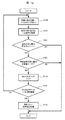
図10は、図7で示した湿度センサ37の故障診断を実行する制御フローを示したフローチャート図であり、図7と共に説明する
まずステップS100では、温度センサ38から所定サンプリング時間毎に吸気温度値を取得し、同様に湿度センサ37から所定サンプリング時間毎に相対湿度値を取得し、取得した温度値と相対湿度値に対して図9に示したデジタルフィルタリング処理を実行する。これが完了するとステップS101に移行する。尚、このデジタルフィルタリング処理は別の処理ルーチンで求めておいても良く、以下のステップS101で読み取るようにしても良いものである。
FIG. 10 is a flowchart showing a control flow for executing a failure diagnosis of the
ステップS101では、図7の(a)、(d)に示すように、ステップS100でフィルタリングした吸気温度値と相対湿度値を一定の時間間隔のサンプリング時間tで取得する。この時間間隔は、例えば図9に示しているように50回の移動平均する時間に対応して決められている。吸気温度と相対湿度を一定の時間間隔で取得するとステップS102に移行する。 In step S101, as shown in FIGS. 7A and 7D, the intake air temperature value and the relative humidity value filtered in step S100 are acquired at a sampling time t at a constant time interval. For example, as shown in FIG. 9, this time interval is determined in correspondence with the time of 50 moving averages. When the intake air temperature and the relative humidity are acquired at regular time intervals, the process proceeds to step S102.
ステップS102では、図7の(b)に示すように、ステップS101で取得した吸気温度値が前回取得した吸気温度値と比較して、その変化量(今回取得した温度値―前回取得した温度値)が増加側で診断開始閾値である所定値以上かどうかを判定する。所定値以上のときは診断条件が成立したとして次のステップS103へ移行し、所定値以上でないときは診断条件が成立していないとして、故障診断を実施しないでエンドに抜けてこの処理を終了する。 In step S102, as shown in FIG. 7B, the intake air temperature value acquired in step S101 is compared with the intake air temperature value acquired last time, and the change amount (temperature value acquired this time−temperature value acquired last time). ) Is greater than or equal to a predetermined value that is a diagnosis start threshold on the increase side. If it is equal to or greater than the predetermined value, the process proceeds to the next step S103 because the diagnosis condition is satisfied. If it is not equal to or greater than the predetermined value, it is determined that the diagnosis condition is not satisfied. .
ステップS103では、図7の(d)に示すように、ステップS101で取得した相対湿度値が、前回取得した相対湿度値と比較して、その変化量(今回で取得した相対湿度値―前回で取得した相対湿度値)が増加側で故障判定閾値である所定値以上か判定する。所定値以上のときは故障が発生していると見做してしてステップS104へ移行し、所定値以上でないときは、故障が発生していないとしてエンドに抜けてこの処理を終了する。 In step S103, as shown in FIG. 7D, the relative humidity value acquired in step S101 is compared with the previously acquired relative humidity value, and the amount of change (the relative humidity value acquired this time minus the previous time). It is determined whether the acquired relative humidity value is equal to or greater than a predetermined value that is a failure determination threshold on the increase side. If it is equal to or greater than the predetermined value, it is assumed that a failure has occurred, and the process proceeds to step S104. If it is not equal to or greater than the predetermined value, the process ends after determining that no failure has occurred.
このように、ステップS102で吸気温度の変化量が所定値以上に上昇していると判断された状態で、ステップS103で相対湿度の変化量が所定値以上に上昇していると判断されると、吸気温度と湿度の相関が一致しないので、湿度センサに故障が発生していると見做すことができる。つまり、吸気温度が上昇すると本来では相対湿度は低下するが、吸気温度が上昇しているのに相対湿度が上昇していると判断されると湿度センサに故障が発生していると見做すことができる。ただ、1回の故障検出では故障検出の信憑性に課題があるので、このステップS103が完了するとステップS104に移行する。 As described above, when it is determined in step S102 that the amount of change in intake air temperature has risen to a predetermined value or higher, it is determined in step S103 that the amount of change in relative humidity has increased to a predetermined value or higher. Since the correlation between the intake air temperature and humidity does not match, it can be considered that a failure has occurred in the humidity sensor. In other words, if the intake air temperature rises, the relative humidity naturally decreases, but if it is determined that the intake air temperature has risen but the relative humidity has risen, it is considered that the humidity sensor has failed. be able to. However, since there is a problem in the reliability of failure detection in one failure detection, when this step S103 is completed, the process proceeds to step S104.
ステップS104では、図7の(e)に示すように、故障の検出毎に湿度センサNGカウンタを「1」だけ増やしていき、故障検出の回数を増やして故障発生の確度を高めるようにしている。このステップS104が完了するとステップS105に移行する。 In step S104, as shown in FIG. 7E, the humidity sensor NG counter is incremented by “1” every time a failure is detected, and the number of times of failure detection is increased to increase the probability of occurrence of the failure. . When step S104 is completed, the process proceeds to step S105.
ステップS105では、図7の(e)に示すように、湿度センサNGカウンタの値が湿度センサ37のNG判定閾値を超えたときは、湿度センサ37に故障が発生していると確定診断してステップ106に移行する。一方、湿度センサNGカウンタの値がNG判定閾値を超えないときは、湿度センサNGカウンタのカウントを継続するために、再びステップS100に戻るものである。
In step S105, as shown in FIG. 7E, when the value of the humidity sensor NG counter exceeds the NG determination threshold value of the
ステップS106では、図7の(f)に示すように、ステップS105で湿度センサ37の故障が確定したので、最終的に湿度センサ37の故障判定フラグを「1」として湿度センサ37の故障判定処理を終了してエンドに抜ける。
In step S106, as shown in FIG. 7F, since the failure of the
このようにして、吸気の相対帯湿度と吸気の温度の相関関係から温度が上昇した場合に相対湿度が上昇すると、湿度センサの故障として判断することができるようになる。 In this way, if the relative humidity increases when the temperature rises from the correlation between the relative humidity of the intake air and the temperature of the intake air, it can be determined that the humidity sensor has failed.
次に、図11は図6に示す湿度センサ故障判定手段52の判定方法の変形例を示している。図11では、吸気温度変化と相対湿度変化の相対関係から、湿度センサ37の故障診断を実行する例である。この図では吸気温度と相対湿度が下降したときの例を示している。
Next, FIG. 11 shows a modification of the determination method of the humidity sensor failure determination means 52 shown in FIG. FIG. 11 shows an example in which failure diagnosis of the
吸気温度と相対湿度を一定の時間間隔(サンプリング時間t)で測定し、(a)、(b)で示すようにt時間当たりの吸気温度の変化量ΔTを算出する。ここで、(b)にある通りΔTが診断開始閾値を超えた時(下回った時)に診断を実行するものである。この診断開始閾値は吸気温度が下降方向にある時に設定されるものである。 The intake air temperature and the relative humidity are measured at a constant time interval (sampling time t), and the change amount ΔT of the intake air temperature per t time is calculated as shown in (a) and (b). Here, as shown in (b), the diagnosis is executed when ΔT exceeds (below) the diagnosis start threshold. This diagnosis start threshold is set when the intake air temperature is in the downward direction.
同様に、(c)、(d)に示すようにt時間当たりの相対湿度の変化量ΔRHを測定し、(d)にある通りΔRHが故障判定閾値を超えた時(下回った時)に故障が発生したと判断するものである。したがって、ΔTが所定値(診断開始閾値)以以上、かつΔRHが所定値(故障判定閾値)以上に下回った場合に、(e)に示すように湿度センサNGカウンタを「1」だけ増やすようにする。 Similarly, as shown in (c) and (d), the amount of change ΔRH in the relative humidity per t time is measured, and when ΔRH exceeds the failure judgment threshold as shown in (d), a failure occurs. Is determined to have occurred. Therefore, when ΔT is equal to or greater than a predetermined value (diagnosis start threshold) and ΔRH is less than a predetermined value (failure determination threshold), the humidity sensor NG counter is increased by “1” as shown in (e). To do.
そして、(f)にあるように湿度センサNGカウンタが所定回数(例えば3)以上となったとき、湿度センサの故障判定フラグを「1」にして、湿度センサが故障していると確定診断することができる。尚、湿度センサNGカウンタが所定回数は任意であるが、ΔRHが所定値以下に変化した時は故障判定フラグは「0」にリセットされるものである。 When the humidity sensor NG counter reaches a predetermined number of times (for example, 3) or more as shown in (f), the failure determination flag of the humidity sensor is set to “1” to make a definite diagnosis that the humidity sensor has failed. be able to. The humidity sensor NG counter can be arbitrarily set a predetermined number of times, but when ΔRH changes below a predetermined value, the failure determination flag is reset to “0”.
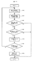
図12は、図11で示した湿度センサ37の故障診断を実行する制御フローを示したフローチャート図であり、図11と共に説明する。
FIG. 12 is a flowchart showing a control flow for executing failure diagnosis of the
まずステップS120では、温度センサ38から所定サンプリング時間毎に吸気温度値を取得し、同様に湿度センサ37から所定サンプリング時間毎に相対湿度値を取得し、取得した吸気温度値と相対湿度値に対して図9に示したデジタルフィルタリング処理を実行する。これが完了するとステップS121に移行する。
First, in step S120, the intake air temperature value is acquired from the
ステップS121では、図11の(a)、(d)に示すように、ステップS120でフィルタリングした吸気温度値と相対湿度値を一定の時間間隔のサンプリング時間tで取得する。この時間間隔は、例えば図9に示しているように50回の移動平均する時間に対応して決められている。吸気温度と相対湿度を一定の時間間隔で取得するとステップS122に移行する。 In step S121, as shown in FIGS. 11A and 11D, the intake air temperature value and the relative humidity value filtered in step S120 are acquired at a sampling time t at a constant time interval. For example, as shown in FIG. 9, this time interval is determined in correspondence with the time of 50 moving averages. When the intake air temperature and the relative humidity are acquired at regular time intervals, the process proceeds to step S122.
ステップS122では、図11の(b)に示すように、ステップS121で取得した吸気温度値が前回取得した吸気温度値と比較して、その変化量(今回取得した温度値―前回取得した温度値)が減少側で診断開始閾値である所定値以上かどうかを判定する。所定値以上のときは診断条件が成立したとして次のステップS123へ移行し、所定値以上でないときは診断条件が成立していないとして、故障診断を実施しないでエンドに抜けてこの処理を終了する。 In step S122, as shown in FIG. 11B, the intake air temperature value acquired in step S121 is compared with the intake air temperature value acquired last time, and the change amount (temperature value acquired this time−temperature value acquired last time). ) Is greater than or equal to a predetermined value that is a diagnosis start threshold on the decreasing side. If it is equal to or greater than the predetermined value, the process proceeds to the next step S123 because the diagnosis condition is satisfied. If it is not equal to or greater than the predetermined value, it is determined that the diagnosis condition is not satisfied. .
ステップS123では、図11の(d)に示すように、ステップS121で取得した相対湿度値が、前回取得した相対湿度値と比較して、その変化量(今回で取得した相対湿度値―前回で取得した相対湿度値)が減少側で故障判定閾値である所定値以上に下回ったか判定する。所定値以上に下回ると故障が発生していると見做してしてステップS124へ移行し、所定値以上に下回っていないときは、故障が発生していないとしてエンドに抜けてこの処理を終了する。 In step S123, as shown in FIG. 11D, the relative humidity value acquired in step S121 is compared with the previously acquired relative humidity value, and the amount of change (the relative humidity value acquired this time minus the previous time). It is determined whether the acquired relative humidity value is lower than a predetermined value that is a failure determination threshold on the decrease side. If it is less than the predetermined value, it is assumed that a failure has occurred, and the process proceeds to step S124. If it is not less than the predetermined value, it is determined that no failure has occurred and the process ends and the process ends. To do.
このように、ステップS122で吸気温度の変化量が所定値以上に減少していると判断された状態で、ステップS123で相対湿度の変化量が所定値以上に減少されていると判断されると、吸気温度と湿度の相関が一致しないので、湿度センサに故障が発生していると見做すことができる。つまり、吸気温度が低下すると本来では相対湿度は上昇するが、吸気温度が低下しているのに相対湿度が低下していると判断されると湿度センサに故障が発生していると見做すことができる。また、図10と同様に1回の故障検出では故障検出の信憑性に課題があるので、このステップS123が完了するとステップS124に移行する。 As described above, when it is determined in step S122 that the change amount of the intake air temperature has decreased to a predetermined value or more, it is determined in step S123 that the change amount of the relative humidity has been decreased to a predetermined value or more. Since the correlation between the intake air temperature and humidity does not match, it can be considered that a failure has occurred in the humidity sensor. In other words, when the intake air temperature decreases, the relative humidity naturally increases, but if it is determined that the intake air temperature has decreased but the relative humidity has decreased, it is assumed that the humidity sensor has failed. be able to. Similarly to FIG. 10, there is a problem with the reliability of failure detection in one failure detection, and when step S123 is completed, the process proceeds to step S124.
ステップS124では、図11の(e)に示すように、故障の検出毎に湿度センサNGカウンタを「1」だけ増やしていき、故障検出の回数を増やして故障発生の確度を高めるようにしている。このステップS124が完了するとステップS125に移行する。 In step S124, as shown in FIG. 11E, the humidity sensor NG counter is incremented by “1” every time a failure is detected, and the number of times of failure detection is increased to increase the probability of occurrence of the failure. . When step S124 is completed, the process proceeds to step S125.
ステップS125では、図11の(e)に示すように、湿度センサNGカウンタの値が湿度センサ37のNG判定閾値を超えたときは、湿度センサ37に故障が発生していると確定診断してステップ126に移行する。一方、湿度センサNGカウンタの値がNG判定閾値を超えないときは、湿度センサNGカウンタのカウントを継続するために、再びステップS120に戻るものである。
In step S125, as shown in FIG. 11 (e), when the value of the humidity sensor NG counter exceeds the NG determination threshold value of the
ステップS126では、図11の(f)に示すように、ステップS125で湿度センサ37の故障が確定したので、最終的に湿度センサ37の故障判定フラグを「1」として湿度センサ37の故障判定処理を終了してエンドに抜ける。
In step S126, as shown in FIG. 11 (f), since the failure of the
このようにして、吸気の相対帯湿度と吸気温度の相関関係から温度が低下した場合に相対湿度が低下すると、湿度センサの故障として判断することができるようになる。 In this way, if the relative humidity decreases when the temperature decreases due to the correlation between the relative humidity of the intake air and the intake air temperature, it can be determined that the humidity sensor has failed.
次に、図6に示している湿度センサの故障判定を行う制御ブロックの他の実施形態について説明する。図6に示す制御ブロックは、マイクロコンピュータで実行される制御機能をブロックで表現した制御機能部の一部である。この制御機能部には、吸気管内に設けられた吸気湿度測定手段と吸気温度測定手段からの情報が入力され、制御機能部は、内燃機関が駆動されている状態で、吸気湿度測定手段からの相対湿度情報が所定の上限値、或いは所定の下限値、或いは所定の上下限値に張り付いた場合に吸気湿度測定手段が故障していると判定する診断機能を備えている。 Next, another embodiment of the control block that performs failure determination of the humidity sensor shown in FIG. 6 will be described. The control block shown in FIG. 6 is a part of a control function unit that expresses a control function executed by the microcomputer as a block. Information from the intake air humidity measuring means and the intake air temperature measuring means provided in the intake pipe is input to the control function unit, and the control function unit receives the information from the intake humidity measurement means while the internal combustion engine is driven. When the relative humidity information sticks to a predetermined upper limit value, a predetermined lower limit value, or a predetermined upper and lower limit value, a diagnosis function is provided that determines that the intake humidity measuring means has failed.
そして、図13には本発明の他の実施形態である図6に示す湿度センサ故障判定手段52の判定方法の例を示している。図13では、湿度センサ37の出力値が上限値に張り付いたことを検出して湿度センサの故障を検出する例である。特に、この例は湿度センサの回路オープン故障を判断するのに適している。
FIG. 13 shows an example of the determination method of the humidity sensor failure determination means 52 shown in FIG. 6 which is another embodiment of the present invention. FIG. 13 shows an example in which a failure of the humidity sensor is detected by detecting that the output value of the
図13において、吸気温度と相対湿度を一定の時間間隔(サンプリング時間t)で測定し、(a)、(b)で示すようにt時間当たりの吸気温度の変化量ΔTを算出する。ここで、(b)にある通りΔTが診断開始閾値を上側に超えた時に診断を実行するものである。この診断開始閾値は吸気温度が上昇方向にある時に設定されるものである。 In FIG. 13, the intake air temperature and the relative humidity are measured at a constant time interval (sampling time t), and the change amount ΔT of the intake air temperature per t time is calculated as shown in (a) and (b). Here, as shown in (b), the diagnosis is executed when ΔT exceeds the diagnosis start threshold value. This diagnosis start threshold is set when the intake air temperature is in the increasing direction.
同様に、(c)に示すようにt時間当たりの相対湿度を測定し、相対湿度が上限値RHmaxから変化しないことを検出する。そして、ΔTが所定値(診断開始閾値)以上、かつ相対湿度が上限値RHmaxから変化しないと、(d)に示すように湿度センサNGカウンタを「1」だけ増やすようにする。 Similarly, as shown in (c), the relative humidity per t time is measured, and it is detected that the relative humidity does not change from the upper limit value RHmax. If ΔT is equal to or greater than a predetermined value (diagnosis start threshold) and the relative humidity does not change from the upper limit value RHmax, the humidity sensor NG counter is increased by “1” as shown in (d).
そして、(d)、(e)にあるように湿度センサNGカウンタが所定回数(例えば3)以上となったとき、湿度センサの故障判定フラグを「1」にして、湿度センサが故障していると確定診断することができる。尚、湿度センサNGカウンタが所定回数は任意であるが、相対湿度が上限値RHmaxから変化すると故障判定フラグは「0」にリセットされるものである。 Then, as shown in (d) and (e), when the humidity sensor NG counter reaches a predetermined number (for example, 3) or more, the failure determination flag of the humidity sensor is set to “1”, and the humidity sensor has failed. Can be confirmed. The humidity sensor NG counter can be arbitrarily set a predetermined number of times, but when the relative humidity changes from the upper limit value RHmax, the failure determination flag is reset to “0”.
図14は、図13で示した湿度センサ37の故障診断を実行する制御フローを示したフローチャート図であり、図13と共に説明する
まずステップS140では、温度センサ38から所定サンプリング時間毎に吸気温度値を取得し、同様に湿度センサ37から所定サンプリング時間毎に相対湿度値を取得し、取得した吸気温度値と相対湿度値に対して図9に示したデジタルフィルタリング処理を実行する。これが完了するとステップS141に移行する。
FIG. 14 is a flowchart showing a control flow for executing failure diagnosis of the
ステップS141では、図13の(a)、(d)に示すように、ステップS140でフィルタリングした吸気温度値と相対湿度値を一定の時間間隔のサンプリング時間tで取得する。この時間間隔は、例えば図9に示しているように50回の移動平均する時間に対応して決められている。吸気温度と相対湿度を一定の時間間隔で取得するとステップS142に移行する。 In step S141, as shown in FIGS. 13A and 13D, the intake air temperature value and the relative humidity value filtered in step S140 are acquired at a sampling time t at a constant time interval. For example, as shown in FIG. 9, this time interval is determined in correspondence with the time of 50 moving averages. When the intake air temperature and the relative humidity are acquired at regular time intervals, the process proceeds to step S142.
ステップS142では、図13の(b)に示すように、ステップS141で取得した吸気温度値が前回取得した吸気温度値と比較して、その変化量(今回取得した温度値―前回取得した温度値)が増加側で診断開始閾値である所定値以上かどうかを判定する。所定値以上のときは診断条件が成立したとして次のステップS143へ移行し、所定値以上でないときは診断条件が成立していないとして、故障診断を実施しないでエンドに抜けてこの処理を終了する。 In step S142, as shown in FIG. 13B, the intake air temperature value acquired in step S141 is compared with the intake air temperature value acquired last time, and the change amount (temperature value acquired this time−temperature value acquired last time). ) Is greater than or equal to a predetermined value that is a diagnosis start threshold on the increase side. If it is equal to or greater than the predetermined value, the process proceeds to the next step S143 because the diagnosis condition is satisfied. If it is not equal to or greater than the predetermined value, it is determined that the diagnosis condition is not satisfied. .
ステップS143では、図13の(c)に示すように、ステップS141で取得した相対湿度値が、上限値RHmaxから変化するか或いはしないかを判断する。上限値RHmaxから変化しないときは故障が発生していると見做してしてステップS144へ移行し、変化しているときは、故障が発生していないとしてエンドに抜けてこの処理を終了する。 In step S143, as shown in FIG. 13C, it is determined whether or not the relative humidity value acquired in step S141 changes from the upper limit value RHmax. If the value does not change from the upper limit value RHmax, it is assumed that a failure has occurred, and the process proceeds to step S144. If the value has changed, it is determined that no failure has occurred and the process ends and the process ends. .
このように、ステップS142で吸気温度の変化量が所定値以上に上昇していると判断された状態で、ステップS143で上限値RHmaxから変化しないと判断されると、湿度センサに故障が発生していると見做すことができる。ただ、1回の故障検出では故障検出の信憑性に課題があるので、このステップS143が完了するとステップS144に移行する。 As described above, if it is determined in step S142 that the amount of change in the intake air temperature has risen to a predetermined value or more and it is determined in step S143 that there is no change from the upper limit value RHmax, a failure occurs in the humidity sensor. Can be regarded as being. However, since there is a problem with the reliability of failure detection in one failure detection, when step S143 is completed, the process proceeds to step S144.
ステップS144では、図13の(d)に示すように、上限値RHmaxの検出毎に湿度センサNGカウンタを「1」だけ増やしていき、故障検出の回数を増やして故障発生の確度を高めるようにしている。このステップS144が完了するとステップS145に移行する。 In step S144, as shown in FIG. 13D, the humidity sensor NG counter is incremented by “1” every time the upper limit value RHmax is detected, and the number of failure detections is increased to increase the accuracy of failure occurrence. ing. When step S144 is completed, the process proceeds to step S145.
ステップS145では、図13の(d)に示すように、湿度センサNGカウンタの値が湿度センサ37のNG判定閾値を超えたときは、湿度センサ37に故障が発生していると確定診断してステップ146に移行する。一方、湿度センサNGカウンタの値がNG判定閾値を超えないときは、湿度センサNGカウンタのカウントを継続するために、再びステップS140に戻るものである。
In step S145, as shown in FIG. 13D, when the value of the humidity sensor NG counter exceeds the NG determination threshold value of the
ステップS146では、図13の(e)に示すように、ステップS105で湿度センサ37の故障が確定したので、最終的に湿度センサ37の故障判定フラグを「1」として湿度センサ37の故障判定処理を終了してエンドに抜ける。
In step S146, as shown in FIG. 13E, since the failure of the
このようにして、相対帯湿度が上限値RHmaに張り付くと湿度センサの故障として判断することができるようになる。 In this way, when the relative band humidity sticks to the upper limit value RHma, it can be determined that the humidity sensor has failed.
次に、図15は図6に示す湿度センサ故障判定手段52の判定方法の変形例を示している。図15では、湿度センサの出力値が下限値に張り付いたことを検出して湿度センサの故障を検出する例である。特に、この例は湿度センサの回路ショート故障を判断するのに適している。 Next, FIG. 15 shows a modification of the determination method of the humidity sensor failure determination means 52 shown in FIG. FIG. 15 shows an example of detecting a failure of the humidity sensor by detecting that the output value of the humidity sensor has stuck to the lower limit value. In particular, this example is suitable for determining a short circuit failure of the humidity sensor.
図15において、吸気温度と相対湿度を一定の時間間隔(サンプリング時間t)で測定し、(a)、(b)で示すようにt時間当たりの吸気温度の変化量ΔTを算出する。ここで、(b)にある通りΔTが診断開始閾値を下側に超えた時に診断を実行するものである。この診断開始閾値は吸気温度が下降方向にある時に設定されるものである。 In FIG. 15, the intake air temperature and the relative humidity are measured at a constant time interval (sampling time t), and the change amount ΔT of the intake air temperature per t time is calculated as shown in (a) and (b). Here, as shown in (b), the diagnosis is executed when ΔT exceeds the diagnosis start threshold value. This diagnosis start threshold is set when the intake air temperature is in the downward direction.
同様に、(c)に示すようにt時間当たりの相対湿度を測定し、相対湿度が上限値RHminから変化しないことを検出する。そして、ΔTが所定値(診断開始閾値)以上、かつ相対湿度が上限値RHminから変化しないと、(d)に示すように湿度センサNGカウンタを「1」だけ増やすようにする。 Similarly, as shown in (c), the relative humidity per t time is measured, and it is detected that the relative humidity does not change from the upper limit value RHmin. If ΔT is equal to or greater than a predetermined value (diagnosis start threshold) and the relative humidity does not change from the upper limit value RHmin, the humidity sensor NG counter is increased by “1” as shown in (d).
そして、(d)、(e)にあるように湿度センサNGカウンタが所定回数(例えば3)以上となったとき、湿度センサの故障判定フラグを「1」にして、湿度センサが故障していると確定診断することができる。尚、湿度センサNGカウンタが所定回数は任意であるが、相対湿度が上限値RHminから変化すると故障判定フラグは「0」にリセットされるものである。 Then, as shown in (d) and (e), when the humidity sensor NG counter reaches a predetermined number (for example, 3) or more, the failure determination flag of the humidity sensor is set to “1”, and the humidity sensor has failed. Can be confirmed. The humidity sensor NG counter can be arbitrarily set a predetermined number of times, but when the relative humidity changes from the upper limit value RHmin, the failure determination flag is reset to “0”.
図16は、図15で示した湿度センサ37の故障診断を実行する制御フローを示したフローチャート図であり、図15と共に説明する
まずステップS160では、温度センサ38から所定サンプリング時間毎に吸気温度値を取得し、同様に湿度センサ37から所定サンプリング時間毎に相対湿度値を取得し、取得した吸気温度値と相対湿度値に対して図9に示したデジタルフィルタリング処理を実行する。これが完了するとステップS161に移行する。
FIG. 16 is a flowchart showing a control flow for executing failure diagnosis of the
ステップS161では、図13の(a)、(d)に示すように、ステップS160でフィルタリングした吸気温度値と相対湿度値を一定の時間間隔のサンプリング時間tで取得する。この時間間隔は、例えば図9に示しているように50回の移動平均する時間に対応して決められている。吸気温度と相対湿度を一定の時間間隔で取得するとステップS162に移行する。 In step S161, as shown in FIGS. 13A and 13D, the intake air temperature value and the relative humidity value filtered in step S160 are acquired at a sampling time t at a constant time interval. For example, as shown in FIG. 9, this time interval is determined in correspondence with the time of 50 moving averages. When the intake air temperature and the relative humidity are acquired at regular time intervals, the process proceeds to step S162.
ステップS162では、図15の(b)に示すように、ステップS161で取得した吸気温度値が前回取得した吸気温度値と比較して、その変化量(今回取得した温度値―前回取得した温度値)が減少側で診断開始閾値である所定値以上に下回ったかどうかを判定する。所定値以上に下回ったときは診断条件が成立したとして次のステップS163へ移行し、所定値以上でないときは診断条件が成立していないとして、故障診断を実施しないでエンドに抜けてこの処理を終了する。 In step S162, as shown in FIG. 15B, the intake air temperature value acquired in step S161 is compared with the intake air temperature value acquired last time, and the change amount (temperature value acquired this time−temperature value acquired last time). ) Is less than a predetermined value which is a diagnosis start threshold value on the decreasing side. When the value is below the predetermined value, the process proceeds to the next step S163 because the diagnosis condition is satisfied. When the value is not greater than the predetermined value, the process proceeds to the end without performing the failure diagnosis, assuming that the diagnosis condition is not satisfied. finish.
ステップS163では、図15の(c)に示すように、ステップS161で取得した相対湿度値が、下限値RHminから変化するか或いはしないかを判断する。下限値RHminから変化しないときは故障が発生していると見做してしてステップS164へ移行し、変化しているときは、故障が発生していないとしてエンドに抜けてこの処理を終了する。 In step S163, as shown in FIG. 15C, it is determined whether or not the relative humidity value acquired in step S161 changes from the lower limit value RHmin. If the value does not change from the lower limit value RHmin, it is assumed that a failure has occurred, and the process proceeds to step S164. If the value has changed, it is determined that no failure has occurred and the process ends and the process ends. .
このように、ステップS162で吸気温度の変化量が所定値以上に下まわっていると判断された状態で、ステップS163で下限値RHminから変化しないと判断されると、湿度センサに故障が発生していると見做すことができる。ただ、1回の故障検出では故障検出の信憑性に課題があるので、このステップS163が完了するとステップS164に移行する。 As described above, if it is determined in step S162 that the amount of change in the intake air temperature has fallen below the predetermined value, and it is determined in step S163 that there is no change from the lower limit value RHmin, a failure occurs in the humidity sensor. Can be regarded as being. However, since there is a problem in the reliability of failure detection in one failure detection, when step S163 is completed, the process proceeds to step S164.
ステップS164では、図15の(d)に示すように、下限値RHminの検出毎に湿度センサNGカウンタを「1」だけ増やしていき、故障検出の回数を増やして故障発生の確度を高めるようにしている。このステップS164が完了するとステップS165に移行する。 In step S164, as shown in FIG. 15D, the humidity sensor NG counter is incremented by “1” every time the lower limit value RHmin is detected, and the number of failure detections is increased to increase the probability of occurrence of the failure. ing. When step S164 is completed, the process proceeds to step S165.
ステップS165では、図15の(d)に示すように、湿度センサNGカウンタの値が湿度センサ37のNG判定閾値を超えたときは、湿度センサ37に故障が発生していると確定診断してステップ166に移行する。一方、湿度センサNGカウンタの値がNG判定閾値を超えないときは、湿度センサNGカウンタのカウントを継続するために、再びステップS160に戻るものである。
In step S165, as shown in FIG. 15D, when the value of the humidity sensor NG counter exceeds the NG determination threshold value of the
ステップS166では、図15の(e)に示すように、ステップS165で湿度センサ37の故障が確定したので、最終的に湿度センサ37の故障判定フラグを「1」として湿度センサ37の故障判定処理を終了してエンドに抜ける。
In step S166, as shown in FIG. 15E, since the failure of the
このようにして、相対帯湿度が下限値RHminに張り付くと湿度センサの故障として判断することができるようになる。 In this way, when the relative humidity is stuck to the lower limit value RHmin, it can be determined that the humidity sensor has failed.
ここで、実施例2では上限値RHmaxと下限値RHminのいずれかを用いて湿度センサ37の故障を検出したが、上限値RHmaxと下限値RHminの両方を用いて湿度センサ37の故障を検出するようにしても良いものである。
In the second embodiment, the failure of the
以上述べた通り本発明によれば、吸気管内の相対湿度を測定する吸気湿度測定手段と、吸気温度を測定する吸気温度測定手段を備え、吸気湿度と吸気温度の相関関係に基づき、吸気温度が上昇したときに相対湿度が上昇した場合、或いは、吸気温度が低下したときに相対湿度が低下した場合に湿度センサが故障していると判定するようにしている。 As described above, according to the present invention, the intake humidity measuring means for measuring the relative humidity in the intake pipe and the intake air temperature measuring means for measuring the intake air temperature are provided, and the intake air temperature is determined based on the correlation between the intake air humidity and the intake air temperature. When the relative humidity rises when it rises, or when the relative humidity falls when the intake air temperature falls, it is determined that the humidity sensor has failed.
これによれば、内燃機関が駆動されている状態で湿度センサの故障診断が可能となるため、正常に機能している湿度センサの測定値に基づいて正確な制御目標値を求めることができる。 According to this, since the failure diagnosis of the humidity sensor is possible while the internal combustion engine is driven, an accurate control target value can be obtained based on the measured value of the humidity sensor functioning normally.
尚、本発明は上記した実施例に限定されるものではなく、様々な変形例が含まれる。例えば、上記した実施例は本発明を分かりやすく説明するために詳細に説明したものであり、必ずしも説明した全ての構成を備えるものに限定されるものではない。また、ある実施例の構成の一部を他の実施例の構成に置き換えることが可能であり、また、ある実施例の構成に他の実施例の構成を加えることも可能である。また、各実施例の構成の一部について、他の構成の追加・削除・置換をすることが可能である。 In addition, this invention is not limited to an above-described Example, Various modifications are included. For example, the above-described embodiments have been described in detail for easy understanding of the present invention, and are not necessarily limited to those having all the configurations described. Further, a part of the configuration of one embodiment can be replaced with the configuration of another embodiment, and the configuration of another embodiment can be added to the configuration of one embodiment. Further, it is possible to add, delete, and replace other configurations for a part of the configuration of each embodiment.
10…内燃機関システム、11…シリンダ、11a…シリンダヘッド、11b…シリンダブロック、12…ピストン、13…コンロッド、14…燃焼室、15…点火コイル、16…点かプラグ、17…エアクリーナ、18…スロットルバルブ、19…コレクター、20…吸気マニホールド、21…吸気ポート、22…吸気通路、23…吸気カム軸、24…吸気バルブ、25…燃料噴射弁、26…エアフローセンサ、27…ECU、28…排気カム軸、29…排気バルブ、30…排気通路、31…三元触媒、32…リニア空燃比センサ、33…O2センサ、37…湿度センサ、38…温度センサ。
DESCRIPTION OF
Claims (5)
前記制御機能部には、吸気管内に設けられた吸気湿度測定手段と吸気温度測定手段からの情報が入力され、
前記制御機能部は、前記内燃機関が駆動されている状態で、前記吸気湿度測定手段からの相対湿度情報と前記吸気温度測定手段からの吸気温度情報の相関関係に基づき、前記吸気温度が上昇したときに前記相対湿度が上昇した場合、或いは前記吸気温度が低下したときに前記相対湿度が低下した場合には前記吸気湿度測定手段が故障していると判定する診断機能を備えていることを特徴とする内燃機関用制御装置。 An internal combustion engine having a function of calculating at least one control target value of the internal combustion engine and a function of correcting at least one control target value of the control target value according to the magnitude of relative humidity Control device for
Information from the intake air humidity measuring means and the intake air temperature measuring means provided in the intake pipe is input to the control function unit,
The control function unit increases the intake air temperature based on a correlation between relative humidity information from the intake air humidity measuring unit and intake air temperature information from the intake air temperature measuring unit while the internal combustion engine is driven. When the relative humidity is sometimes raised, or when the relative humidity is lowered when the intake air temperature is lowered, a diagnosis function is provided for determining that the intake humidity measuring means has failed. A control device for an internal combustion engine.
前記診断機能は、
前記吸気温度が上昇した時の前記吸気温度の変化量が所定値以上で、かつ前記相対湿度の変化量が所定値以上の場合、或いは前記吸気温度が低下した時の前記吸気温度の変化量が所定値以上で、かつ前記相対湿度の変化量が所定値以上の場合に前記吸気湿度測定手段が故障していると判定することを特徴とする内燃機関用制御装置。 The control device for an internal combustion engine according to claim 1,
The diagnostic function is:
The amount of change in the intake air temperature when the amount of change in the intake air temperature when the intake air temperature rises is greater than or equal to a predetermined value and the amount of change in the relative humidity is greater than or equal to a predetermined value, or when the intake air temperature decreases. A control apparatus for an internal combustion engine, wherein when the amount of change in the relative humidity is equal to or greater than a predetermined value, the intake humidity measuring means is determined to be malfunctioning.
前記制御機能部には、吸気管内に設けられた吸気湿度測定手段と吸気温度測定手段からの情報が入力され、
前記制御機能部は、前記内燃機関が駆動されている状態で、前記吸気湿度測定手段からの相対湿度情報が所定の上限値、或いは所定の下限値、或いは所定の上下限値に張り付いた場合に前記吸気湿度測定手段が故障していると判定する診断機能を備えていることを特徴とする内燃機関用制御装置。 An internal combustion engine having a function of calculating at least one control target value of the internal combustion engine and a function of correcting at least one control target value of the control target value according to the magnitude of relative humidity Control device for
Information from the intake air humidity measuring means and the intake air temperature measuring means provided in the intake pipe is input to the control function unit,
The control function unit, when the relative humidity information from the intake humidity measuring means sticks to a predetermined upper limit value, a predetermined lower limit value, or a predetermined upper and lower limit value while the internal combustion engine is driven A control device for an internal combustion engine, further comprising a diagnostic function for determining that the intake humidity measuring means is malfunctioning.
前記制御機能部は、前記吸気湿度測定手段からの相対湿度情報と前記吸気温度測定手段からの吸気温度情報をデジタルフィルタリング処理を行って求めることを特徴とする内燃機関用制御装置。 In the control device for an internal combustion engine according to claim 1 or 3,
The control device for an internal combustion engine, wherein the control function unit obtains the relative humidity information from the intake humidity measuring means and the intake air temperature information from the intake air temperature measuring means by performing a digital filtering process.
前記診断機能は、故障と判定する回数を計数し、所定の回数に達すると故障を確定することを特徴とする内燃機関用制御装置。 In the control device for an internal combustion engine according to claim 1 or 3,
The internal combustion engine control apparatus according to claim 1, wherein the diagnosis function counts the number of times that the failure is determined and determines the failure when the predetermined number of times is reached.
Priority Applications (1)
| Application Number | Priority Date | Filing Date | Title |
|---|---|---|---|
| JP2015138202A JP2017020406A (en) | 2015-07-10 | 2015-07-10 | Control device for internal combustion engine |
Applications Claiming Priority (1)
| Application Number | Priority Date | Filing Date | Title |
|---|---|---|---|
| JP2015138202A JP2017020406A (en) | 2015-07-10 | 2015-07-10 | Control device for internal combustion engine |
Publications (2)
| Publication Number | Publication Date |
|---|---|
| JP2017020406A true JP2017020406A (en) | 2017-01-26 |
| JP2017020406A5 JP2017020406A5 (en) | 2017-10-26 |
Family
ID=57887703
Family Applications (1)
| Application Number | Title | Priority Date | Filing Date |
|---|---|---|---|
| JP2015138202A Pending JP2017020406A (en) | 2015-07-10 | 2015-07-10 | Control device for internal combustion engine |
Country Status (1)
| Country | Link |
|---|---|
| JP (1) | JP2017020406A (en) |
Cited By (3)
| Publication number | Priority date | Publication date | Assignee | Title |
|---|---|---|---|---|
| JP2017125436A (en) * | 2016-01-13 | 2017-07-20 | トヨタ自動車株式会社 | Abnormality detection device for humidity sensor |
| KR101806372B1 (en) | 2016-12-09 | 2018-01-10 | 현대오트론 주식회사 | Diagnosis Method of the Relative Humidity Sensor for Vehicle |
| JP2018199367A (en) * | 2017-05-25 | 2018-12-20 | 株式会社デンソー | Electronic control unit |
Citations (9)
| Publication number | Priority date | Publication date | Assignee | Title |
|---|---|---|---|---|
| JPS633275A (en) * | 1986-06-23 | 1988-01-08 | Fujitsu Ten Ltd | Abnormality detector for sensor system |
| JPS6441753A (en) * | 1987-08-07 | 1989-02-14 | Sanyo Electric Co | Air conditioner of basement for living |
| JPH0968146A (en) * | 1995-09-01 | 1997-03-11 | Mitsubishi Electric Corp | Internal combustion engine control device |
| JP2001097032A (en) * | 1999-09-30 | 2001-04-10 | Denso Corp | Air conditioner for vehicle |
| JP2001227790A (en) * | 2000-02-18 | 2001-08-24 | Fujitsu General Ltd | Device for diagnosing fault of sensor of air conditioner |
| JP2004229446A (en) * | 2003-01-24 | 2004-08-12 | Nissin Electric Co Ltd | Method of detecting insulator contamination |
| US20120227714A1 (en) * | 2011-03-10 | 2012-09-13 | Ford Global Technologies, Llc | Method and System for Humidity Sensor Diagnostics |
| JP2015078637A (en) * | 2013-10-16 | 2015-04-23 | 日立オートモティブシステムズ株式会社 | Internal combustion engine control device |
| JP2015114884A (en) * | 2013-12-12 | 2015-06-22 | 株式会社デンソー | Physical quantity sensor |
-
2015
- 2015-07-10 JP JP2015138202A patent/JP2017020406A/en active Pending
Patent Citations (9)
| Publication number | Priority date | Publication date | Assignee | Title |
|---|---|---|---|---|
| JPS633275A (en) * | 1986-06-23 | 1988-01-08 | Fujitsu Ten Ltd | Abnormality detector for sensor system |
| JPS6441753A (en) * | 1987-08-07 | 1989-02-14 | Sanyo Electric Co | Air conditioner of basement for living |
| JPH0968146A (en) * | 1995-09-01 | 1997-03-11 | Mitsubishi Electric Corp | Internal combustion engine control device |
| JP2001097032A (en) * | 1999-09-30 | 2001-04-10 | Denso Corp | Air conditioner for vehicle |
| JP2001227790A (en) * | 2000-02-18 | 2001-08-24 | Fujitsu General Ltd | Device for diagnosing fault of sensor of air conditioner |
| JP2004229446A (en) * | 2003-01-24 | 2004-08-12 | Nissin Electric Co Ltd | Method of detecting insulator contamination |
| US20120227714A1 (en) * | 2011-03-10 | 2012-09-13 | Ford Global Technologies, Llc | Method and System for Humidity Sensor Diagnostics |
| JP2015078637A (en) * | 2013-10-16 | 2015-04-23 | 日立オートモティブシステムズ株式会社 | Internal combustion engine control device |
| JP2015114884A (en) * | 2013-12-12 | 2015-06-22 | 株式会社デンソー | Physical quantity sensor |
Cited By (3)
| Publication number | Priority date | Publication date | Assignee | Title |
|---|---|---|---|---|
| JP2017125436A (en) * | 2016-01-13 | 2017-07-20 | トヨタ自動車株式会社 | Abnormality detection device for humidity sensor |
| KR101806372B1 (en) | 2016-12-09 | 2018-01-10 | 현대오트론 주식회사 | Diagnosis Method of the Relative Humidity Sensor for Vehicle |
| JP2018199367A (en) * | 2017-05-25 | 2018-12-20 | 株式会社デンソー | Electronic control unit |
Similar Documents
| Publication | Publication Date | Title |
|---|---|---|
| US9151204B2 (en) | Device for detecting particulate matter in exhaust gas | |
| JP4462142B2 (en) | Control device for internal combustion engine | |
| US7040307B2 (en) | System for diagnosing degradation of air-fuel sensor | |
| US7387011B2 (en) | Deterioration diagnosis system for exhaust gas sensor | |
| US9945312B2 (en) | Abnormality diagnosis device for exhaust gas sensor | |
| JP3783778B2 (en) | Failure judgment device for exhaust pressure raising means | |
| US20130318948A1 (en) | Soot sensor functional capability monitoring | |
| JP2009221992A (en) | Malfunction diagnosing apparatus for exhaust gas sensor | |
| JP5772956B2 (en) | Exhaust sensor deterioration diagnosis device and deterioration diagnosis method | |
| US8463524B2 (en) | Air quantity control device of internal combustion engine | |
| JP2005163696A (en) | Misfire detection device of internal combustion engine | |
| JP6058102B1 (en) | Control device for internal combustion engine and control method for internal combustion engine | |
| JP6494759B2 (en) | Control device for internal combustion engine | |
| JP2017020406A (en) | Control device for internal combustion engine | |
| JP4403156B2 (en) | Oxygen sensor diagnostic device for internal combustion engine | |
| WO2016035498A1 (en) | Engine control apparatus | |
| JP2014020210A (en) | Suction air volume measuring device for engine | |
| JP5413248B2 (en) | Exhaust gas purification system for internal combustion engine | |
| JP2006057523A (en) | Failure diagnosis device for engine control system | |
| JP6422899B2 (en) | Control device for internal combustion engine | |
| JP4470661B2 (en) | Exhaust gas sensor abnormality diagnosis device | |
| JP4210940B2 (en) | Abnormality diagnosis device for intake system sensor | |
| JP3855720B2 (en) | Abnormality diagnosis device for catalyst early warm-up control system of internal combustion engine | |
| JP2009299545A (en) | Electronic control system and control method | |
| JP6659267B2 (en) | Control device for internal combustion engine |
Legal Events
| Date | Code | Title | Description |
|---|---|---|---|
| A521 | Request for written amendment filed |
Free format text: JAPANESE INTERMEDIATE CODE: A523 Effective date: 20170914 |
|
| A621 | Written request for application examination |
Free format text: JAPANESE INTERMEDIATE CODE: A621 Effective date: 20170914 |
|
| A977 | Report on retrieval |
Free format text: JAPANESE INTERMEDIATE CODE: A971007 Effective date: 20180628 |
|
| A131 | Notification of reasons for refusal |
Free format text: JAPANESE INTERMEDIATE CODE: A131 Effective date: 20180710 |
|
| A521 | Request for written amendment filed |
Free format text: JAPANESE INTERMEDIATE CODE: A523 Effective date: 20180906 |
|
| A02 | Decision of refusal |
Free format text: JAPANESE INTERMEDIATE CODE: A02 Effective date: 20181225 |