JP2017019665A - Entangled parts separation device - Google Patents

Entangled parts separation device Download PDF

Info

Publication number
JP2017019665A
JP2017019665A JP2016162558A JP2016162558A JP2017019665A JP 2017019665 A JP2017019665 A JP 2017019665A JP 2016162558 A JP2016162558 A JP 2016162558A JP 2016162558 A JP2016162558 A JP 2016162558A JP 2017019665 A JP2017019665 A JP 2017019665A
Authority
JP
Japan
Prior art keywords
protrusions
parts
drum
entangled
opening
Prior art date
Legal status (The legal status is an assumption and is not a legal conclusion. Google has not performed a legal analysis and makes no representation as to the accuracy of the status listed.)
Granted
Application number
JP2016162558A
Other languages
Japanese (ja)
Other versions
JP6304570B2 (en
JP2017019665A5 (en
Inventor
秀樹 前畑
Hideki Maehata
秀樹 前畑
健三 渡辺
Kenzo Watanabe
健三 渡辺
岩本 仁志
Hitoshi Iwamoto
仁志 岩本
幸彦 倉田
Yukihiko Kurata
幸彦 倉田
Current Assignee (The listed assignees may be inaccurate. Google has not performed a legal analysis and makes no representation or warranty as to the accuracy of the list.)
Maehata Seiki Co Ltd
Original Assignee
Maehata Seiki Co Ltd
Priority date (The priority date is an assumption and is not a legal conclusion. Google has not performed a legal analysis and makes no representation as to the accuracy of the date listed.)
Filing date
Publication date
Application filed by Maehata Seiki Co Ltd filed Critical Maehata Seiki Co Ltd
Priority to JP2016162558A priority Critical patent/JP6304570B2/en
Publication of JP2017019665A publication Critical patent/JP2017019665A/en
Publication of JP2017019665A5 publication Critical patent/JP2017019665A5/ja
Application granted granted Critical
Publication of JP6304570B2 publication Critical patent/JP6304570B2/en
Active legal-status Critical Current
Anticipated expiration legal-status Critical

Links

Images

Abstract

PROBLEM TO BE SOLVED: To provide an entangled parts separation device capable of easily separating parts entangled with each other.SOLUTION: An entangled parts separation device is equipped with a cylindrical drum 10 which includes a first opening portion 11 functioning as an introducing port of parts, and a second opening portion 13 functioning as a discharge port of the parts; a plurality of protrusions 31 which projects out to the inside of the drum 10 from an inner wall 17 of the drum 10; and a drive mechanism which rotates the drum 10 about a rotary shaft intersecting a gravity direction, while a center of the first opening portion 11 is higher than a center of the second opening portion 13.SELECTED DRAWING: Figure 4

Description

この発明は、絡み部品分離装置に関し、絡み合った複数のパーツの絡みを除去する絡み部品分離装置に関する。   The present invention relates to an entangled component separator, and more particularly to an entangled component separator that removes entanglement of a plurality of entangled parts.

近年、生産の自動化が進んでおり、部品の組み付け作業にロボットが利用される。このロボットが組み付けの対象とする部品は、ロボットが掴み取ることができるように、部品の向きを揃えてロボットに供給する必要がある。ロボットに部品を向きを揃えて供給する装置として、部品を振動することによって部品を移動させ、部品が移動する経路中で部品の向きを揃える振動型のパーツフィーダーが知られている。例えば、特開2015−059008号公報には、特定面を向いたチップ部品をピックアップするピックアップ装置に、チップ部品を供給するチップ部品供給装置であって、内筒壁と外筒壁に挟まれた周回状の搬送路を有する振動ボウルと、該振動ボウルを加振する加振器とを備え、前記搬送路は、斜面と、該斜面の上端に連続し該斜面より傾斜が緩やかであって前記ピックアップ装置がピックアップ動作を行なうピックアップ面と、前記斜面の下端と前記ピックアップ面とを接続する段差とを備え、前記加振器は、前記振動ボウルを加振し、チップ部品を前記斜面の下端から上端方向に前記搬送路を移動させると共に、前記斜面上に重なり合ったチップ部品をばらすものであり、前記段差は、ピックアップ面上に残されたチップ部品を反転可能に落下させるものであることを特徴とするチップ部品供給装置が記載されている。   In recent years, production has been automated, and robots are used for assembling parts. The parts to be assembled by the robot need to be supplied to the robot with the parts oriented so that the robot can grasp them. 2. Description of the Related Art As a device that supplies parts to a robot in a uniform orientation, there is known a vibration-type parts feeder that moves parts by vibrating the parts and aligns the parts in a path along which the parts move. For example, Japanese Patent Laying-Open No. 2015-059008 discloses a chip component supply device that supplies a chip component to a pickup device that picks up a chip component facing a specific surface, and is sandwiched between an inner cylinder wall and an outer cylinder wall. A vibrating bowl having a circular conveying path; and a vibrator for vibrating the vibrating bowl, wherein the conveying path is continuous with an inclined surface and an upper end of the inclined surface, and the inclination is gentler than the inclined surface. The pickup device includes a pickup surface on which a pickup operation is performed, and a step connecting the lower end of the slope and the pickup surface, the vibrator vibrates the vibrating bowl, and inserts a chip component from the lower end of the slope. While moving the transport path in the upper end direction, the chip parts overlapping on the slope are separated, and the step reverses the chip parts left on the pickup surface. It describes a chip component feeding apparatus, characterized in that for dropping the capacity.

しかしながら、振動型のパーツフィーダーは、互いに絡み合う複数の部品を分離することができないといった問題がある。
特開2015−059008
However, the vibration-type parts feeder has a problem in that it cannot separate a plurality of components that are intertwined with each other.
JP2015-059008 A

この発明は上述した問題点を解決するためになされたもので、この発明の目的の一つは、互いに絡まったパーツを容易に分離することが可能な絡み部品分離装置を提供することである。   The present invention has been made to solve the above-described problems, and one of the objects of the present invention is to provide an entangled component separating apparatus capable of easily separating parts entangled with each other.

上述した目的を達成するためにこの発明のある局面によれば、絡み部品分離装置は、パーツの導入口となる第1開口部と、パーツの排出口となる第2開口部とを含む円筒状のドラムと、ドラムの側壁からドラムの内側に突出する複数の突起部と、第1開口部の中心が第2開口部の中心より高い状態で、重力方向と交わる回転軸を中心にドラムを回転させる駆動機構と、を備える。   In order to achieve the above-described object, according to one aspect of the present invention, the entangled component separation device includes a first opening serving as a part introduction port and a second opening serving as a part discharge port. Rotate the drum around the rotation axis intersecting the direction of gravity with the drum, the plurality of protrusions protruding from the drum side wall to the inside of the drum, and the center of the first opening higher than the center of the second opening And a drive mechanism.

この局面に従えば、第1開口部の中心が第2開口部の中心より高い状態で、重力方向と交わる回転軸を中心にドラムが回転するので第1開口部に導入されたパーツが第1開口部から第2開口部に向かって移動する。第1開口部に導入されたパーツのうち他のパーツと絡み合った複数のパーツからなるパーツ群は、複数の突起部のいずれかに絡まるので、パーツ群が第2開口部に移動しないようにすることができる。また、複数の突起部のいずれかに絡まったパーツ群はドラムの回転によって上方に持ち上げられた後に重力によって落下する。このため、落下によって、パーツ群に含まれる複数のパーツのうちには他のパーツとの絡まりが解除される場合がある。このため、互いに絡まったパーツを容易に分離することが可能な絡み部品分離装置を提供することができる。   According to this aspect, since the drum rotates around the rotation axis that intersects the direction of gravity in the state where the center of the first opening is higher than the center of the second opening, the parts introduced into the first opening are the first. It moves from the opening toward the second opening. A part group consisting of a plurality of parts intertwined with other parts among the parts introduced into the first opening is entangled with one of the plurality of protrusions, so that the part group does not move to the second opening. be able to. A group of parts entangled with any of the plurality of protrusions is lifted upward by the rotation of the drum and then dropped by gravity. For this reason, entanglement with other parts may be canceled among the plurality of parts included in the part group due to falling. For this reason, the entangled component separation apparatus which can isolate | separate the parts entangled mutually can be provided.

好ましくは、複数の突起部は、ドラムの第1開口部から所定の距離の円周方向に互いに間隔をおいて配置される。   Preferably, the plurality of protrusions are spaced apart from each other in the circumferential direction by a predetermined distance from the first opening of the drum.

好ましくは、複数の突起部は、ドラムの第1開口部からの所定の距離の円筒状の領域に互いに間隔を置いて配置される。   Preferably, the plurality of protrusions are spaced apart from each other in a cylindrical region at a predetermined distance from the first opening of the drum.

好ましくは、パーツがドラムの回転に伴って複数の突起部の2以上に同時に絡むことがないように、複数の突起部の端部間の距離が設定される。   Preferably, the distance between the end portions of the plurality of protrusions is set so that the parts do not entangle with two or more of the plurality of protrusions simultaneously with the rotation of the drum.

好ましくは、パーツの複数がドラムに第1開口部から投入された状態で複数のパーツのうち他のパーツと絡む複数のパーツからなるパーツ群がドラムの回転に伴って複数の突起部の2以上に同時に絡むように、複数の突起部の端部間の距離が設定される。   Preferably, when a plurality of parts are inserted into the drum from the first opening, a part group consisting of a plurality of parts entangled with other parts among the plurality of parts is two or more of the plurality of protrusions as the drum rotates. The distances between the ends of the plurality of protrusions are set so as to be simultaneously entangled with each other.

好ましくは、複数の突起部のそれぞれの複数の端部間の距離の最小値は、パーツの最大値より大きい。   Preferably, the minimum value of the distance between each of the plurality of ends of the plurality of protrusions is greater than the maximum value of the part.

この局面に従えば、複数の突起部のそれぞれの複数の端部間の距離の最小値は、パーツの最大値より大きいので、1つのパーツが複数の第1突起部の2以上に同時に絡まないようにすることができ、ドラムの回転にともなってパーツが動かなくなるのを防止することができる。   According to this aspect, since the minimum value of the distance between the plurality of ends of each of the plurality of protrusions is larger than the maximum value of the parts, one part does not simultaneously entangle with two or more of the plurality of first protrusions. It is possible to prevent the parts from moving as the drum rotates.

好ましくは、複数の突起部それぞれがドラムの内壁に配置される間隔は、パーツの最大長より大きい。   Preferably, the interval at which each of the plurality of protrusions is disposed on the inner wall of the drum is greater than the maximum length of the part.

この局面に従えば、他のパーツと絡まない単独のパーツが複数の突起部の間をすり抜けることが可能となるので、単独のパーツを第2開口部から排出することができる。   According to this aspect, a single part that is not entangled with other parts can pass through between the plurality of protrusions, so that the single part can be discharged from the second opening.

本実施の形態における絡み部品分離装置の一例を示す外観図である。It is an external view which shows an example of the entangled component separation apparatus in this Embodiment. 支持角度が0度の場合における部品分離装置の正面図である。It is a front view of the components separation apparatus in case a support angle is 0 degree | times. 支持角度が0度の場合における部品分離装置の左側面図である。It is a left view of the component separation apparatus in case a support angle is 0 degree | times. 支持角度が0度の場合における部品分離装置の平面図である。It is a top view of the components separation apparatus in case a support angle is 0 degree | times. 本実施の形態における絡み部品分離装置に投入されるパーツの一例を示す平面図である。It is a top view which shows an example of the parts thrown into the entangled components separation apparatus in this Embodiment. ドラムの展開図である。It is an expanded view of a drum. 第1開口部11から距離L1の位置のドラム10の断面図である。3 is a cross-sectional view of the drum 10 at a distance L1 from the first opening 11. FIG. 第1開口部11から距離L2の位置のドラム10の断面図である。2 is a cross-sectional view of the drum 10 at a distance L2 from the first opening 11. FIG. 第1開口部11から距離L7の位置のドラム10の断面図である。3 is a cross-sectional view of the drum 10 at a distance L7 from the first opening 11. FIG. 第1の変形例におけるドラムの展開図である。It is an expanded view of the drum in the 1st modification.

以下、本発明の実施の形態について図面を参照して説明する。以下の説明では同一の部品には同一の符号を付してある。それらの名称および機能も同じである。したがってそれらについての詳細な説明は繰返さない。   Hereinafter, embodiments of the present invention will be described with reference to the drawings. In the following description, the same parts are denoted by the same reference numerals. Their names and functions are also the same. Therefore, detailed description thereof will not be repeated.

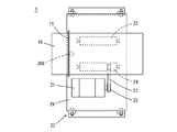
図1は、本実施の形態における絡み部品分離装置の一例を示す外観図である。図1を参照して、絡み部品分離装置1は、円筒状のドラム10と、ドラム10を回転させる駆動機構20と、を含む。駆動機構20は、ドラム10を回転可能な状態で支持する。また、駆動機構20は、ドラム10を、その回転軸39の重力方向に対する角度を調整可能に支持する。ここでは、回転軸39の重力方向に垂直な水平方向に対する角度を支持角度といい、図1では、支持角度がθ(θ>0)となる場合を例に示している。   FIG. 1 is an external view showing an example of an entangled component separation device in the present embodiment. Referring to FIG. 1, the entangled component separation device 1 includes a cylindrical drum 10 and a drive mechanism 20 that rotates the drum 10. The drive mechanism 20 supports the drum 10 in a rotatable state. Moreover, the drive mechanism 20 supports the drum 10 so that the angle with respect to the gravity direction of the rotating shaft 39 can be adjusted. Here, the angle of the rotation shaft 39 with respect to the horizontal direction perpendicular to the gravity direction is referred to as a support angle, and FIG. 1 shows an example in which the support angle is θ (θ> 0).

図2は、支持角度が0度の場合における部品分離装置の正面図である。図3は、支持角度が0度の場合における部品分離装置の左側面図である。図4は、支持角度が0度の場合における部品分離装置の平面図である。図2〜図4を参照して、駆動機構20は、モーター21と、駆動ベルト23と、第1ローラ24と、第2ローラ25と、ストッパー26と、基台29と、を備える。   FIG. 2 is a front view of the component separating apparatus when the support angle is 0 degree. FIG. 3 is a left side view of the component separating apparatus when the support angle is 0 degree. FIG. 4 is a plan view of the component separating apparatus when the support angle is 0 degree. 2 to 4, the drive mechanism 20 includes a motor 21, a drive belt 23, a first roller 24, a second roller 25, a stopper 26, and a base 29.

モーター21、第1ローラ24および第2ローラ25は、それぞれの回転軸が並行となるように基台29に固定される。第1ローラ24および第2ローラ25それぞれの回転軸の基台29からの距離は同じである。第1ローラ24は、モーター21の駆動軸に接続されたプーリー22と駆動ベルト23によって接続されており、モーター21の回転力が第1ローラ24に伝達される。   The motor 21, the first roller 24, and the second roller 25 are fixed to the base 29 so that the respective rotation axes are parallel to each other. The distance from the base 29 of the rotating shaft of each of the first roller 24 and the second roller 25 is the same. The first roller 24 is connected by a pulley 22 connected to the drive shaft of the motor 21 and a drive belt 23, and the rotational force of the motor 21 is transmitted to the first roller 24.

第1ローラ24および第2ローラ25の回転軸を基準に、基台29の方向を定める。基台29の第1ローラ24および第2ローラ25の回転軸と交わる端部を、前方端および後方端という。基台29は、後方端が前方端よりも高くなるように傾きを変更可能である。   The direction of the base 29 is determined based on the rotation axes of the first roller 24 and the second roller 25. The ends of the base 29 that intersect with the rotation axes of the first roller 24 and the second roller 25 are referred to as a front end and a rear end. The inclination of the base 29 can be changed so that the rear end is higher than the front end.

ドラム10は、パーツの導入口となる第1開口部11と、パーツの排出口となる第2開口部13と、その外壁から延びる円環状のフランジ15と、を備える。   The drum 10 includes a first opening 11 serving as a part introduction port, a second opening 13 serving as a part discharge port, and an annular flange 15 extending from an outer wall thereof.

ドラム10は、第1ローラ24および第2ローラ25上に載置される。ドラム10が第1ローラ24および第2ローラ25上に載置される方向は、第1開口部11が基台29の後方端側、第2開口部13が基台29の前方端側となる方向である。このため、ドラム10の回転軸39は、第1ローラ24および第2ローラ25の回転軸と並行であり、ドラム10の側壁からの距離が一定である。   The drum 10 is placed on the first roller 24 and the second roller 25. The direction in which the drum 10 is placed on the first roller 24 and the second roller 25 is such that the first opening 11 is the rear end side of the base 29 and the second opening 13 is the front end side of the base 29. Direction. For this reason, the rotating shaft 39 of the drum 10 is parallel to the rotating shafts of the first roller 24 and the second roller 25, and the distance from the side wall of the drum 10 is constant.

ドラム10が、第1ローラ24および第2ローラ25上に載置された状態で、モーター21が駆動すると、モーター21の回転が駆動ベルト23を介して第1ローラ24に伝えられる。第1ローラ24が回転すると、第1ローラ24がドラム10と接する部分の摩擦力によってドラム10が回転する。さらに、ドラム10が回転すると、ドラム10が第2ローラ25と接する部分の摩擦力によって第2ローラ25が回転する。   When the motor 21 is driven while the drum 10 is placed on the first roller 24 and the second roller 25, the rotation of the motor 21 is transmitted to the first roller 24 via the drive belt 23. When the first roller 24 rotates, the drum 10 is rotated by the frictional force of the portion where the first roller 24 contacts the drum 10. Further, when the drum 10 is rotated, the second roller 25 is rotated by the frictional force of the portion where the drum 10 is in contact with the second roller 25.

ストッパー26は、基台29上で、第1ローラ24および第2ローラの中間に固定される。ストッパー26は、基台29から垂直に伸びる軸26Aと、その軸で回転するローラ26Bとを含む。ドラム10が第1ローラ24および第2ローラ25上に載置された状態において、ストッパー26はドラム10の側面よりも下方となり、ストッパー26のローラ26Bがドラム10のフランジ15の最下端よりも上方となる。ドラム10は、フランジ15がストッパー26のローラ26Bよりも第1開口部11側に位置するように、第1ローラ24および第2ローラ25上に載置される。このため、ドラム10の第1開口部11から第2開口部13に向かう方向への移動は、ドラム10のフランジ15がストッパー26のローラ26Bと接触することによって規制される。したがって、基台29を、その後方端が前方端よりも高くなるように傾きを変更した場合であっても、ドラム10が回転軸39に沿った方向における基台29に対する相対的位置を一定に維持した状態で、ドラム10を回転させることができる。   The stopper 26 is fixed on the base 29 between the first roller 24 and the second roller. The stopper 26 includes a shaft 26A that extends vertically from the base 29 and a roller 26B that rotates about the shaft. When the drum 10 is placed on the first roller 24 and the second roller 25, the stopper 26 is below the side surface of the drum 10, and the roller 26B of the stopper 26 is above the lowermost end of the flange 15 of the drum 10. It becomes. The drum 10 is placed on the first roller 24 and the second roller 25 so that the flange 15 is positioned closer to the first opening 11 than the roller 26B of the stopper 26. For this reason, the movement of the drum 10 in the direction from the first opening 11 toward the second opening 13 is restricted by the flange 15 of the drum 10 coming into contact with the roller 26B of the stopper 26. Therefore, even when the inclination of the base 29 is changed so that the rear end thereof is higher than the front end, the relative position of the drum 10 with respect to the base 29 in the direction along the rotation shaft 39 is constant. The drum 10 can be rotated in the maintained state.

ドラム10は、それぞれがドラム10の内壁から突出する複数の第1突起部31、複数の第2突起部33および複数の第3突起部35を備える。複数の第1突起部31、複数の第2突起部33および複数の第3突起部35それぞれは、ドラム10の内壁から垂直に突出する。   The drum 10 includes a plurality of first protrusions 31, a plurality of second protrusions 33, and a plurality of third protrusions 35, each protruding from the inner wall of the drum 10. Each of the plurality of first protrusions 31, the plurality of second protrusions 33, and the plurality of third protrusions 35 protrudes vertically from the inner wall of the drum 10.

本実施の形態における絡み部品分離装置1において、ドラム10の直径を300mm、第1突起部31の長さを120mm、第2突起部33の長さを60mm、第3突起部35の長さを60mmとしている。   In the entangled component separating apparatus 1 according to the present embodiment, the diameter of the drum 10 is 300 mm, the length of the first protrusion 31 is 120 mm, the length of the second protrusion 33 is 60 mm, and the length of the third protrusion 35 is set. 60 mm.

図5は、本実施の形態における絡み部品分離装置に投入されるパーツの一例を示す平面図である。図5を参照して、パーツは、断面円形で、一部が開口した環状の形状である。パーツは、一部が開口しているため、他のパーツが開口部分から入りこみ、絡みやすい形状である。本実施の形態においては、パーツの最大長を46mmとしている。   FIG. 5 is a plan view showing an example of parts put into the entangled component separation device in the present embodiment. Referring to FIG. 5, the part has a circular shape with a circular cross section and a part opened. Since some of the parts are open, other parts enter from the opening and are easily entangled. In the present embodiment, the maximum part length is 46 mm.

図2〜図4を再度参照して、本実施の形態における絡み部品分離装置1は、ドラム10が支持角度θの傾いた状態で駆動する。ドラム10の第1開口部11から複数のパーツが投入され、ドラム10が回転すると、複数のパーツは、重力によってドラム10内を第1開口部11から第2開口部13に向かう力を受ける。ドラム10は、複数の第1突起部31、複数の第2突起部33および複数の第3突起部35を、有するため、複数のパーツは、複数の第1突起部31、複数の第2突起部33および複数の第3突起部35の間をすり抜けながらドラム10内を第1開口部11から第2開口部13に移動する。   Referring again to FIGS. 2 to 4, the entangled component separation device 1 according to the present embodiment is driven in a state where the drum 10 is inclined at the support angle θ. When a plurality of parts are inserted from the first opening 11 of the drum 10 and the drum 10 rotates, the plurality of parts receive a force from the first opening 11 toward the second opening 13 in the drum 10 due to gravity. Since the drum 10 includes a plurality of first protrusions 31, a plurality of second protrusions 33, and a plurality of third protrusions 35, the plurality of parts include a plurality of first protrusions 31, a plurality of second protrusions. The drum 10 moves from the first opening 11 to the second opening 13 while passing between the portion 33 and the plurality of third protrusions 35.

複数の第1突起部31は、第1開口部11から距離L1の円周方向に所定の間隔で配置される。互いに隣り合う2つの第1突起部31が配置される間隔の最大長は、パーツの最大長の2.5〜3倍であるのが好ましい。このため、第1突起部31の数は、ドラムの直径およびパーツの最大長によって定まる。複数の第1突起部31それぞれの長さは、ドラム10の半径より短い。このため、複数の第1突起部31それぞれは、他の第1突起部31と接触することがないので、1つのパーツが複数の第1突起部31のうちの2以上に同時に絡まる確率を小さくすることができる。   The plurality of first protrusions 31 are arranged at predetermined intervals in the circumferential direction at a distance L1 from the first opening 11. It is preferable that the maximum length of the interval between the two adjacent first protrusions 31 is 2.5 to 3 times the maximum length of the part. For this reason, the number of the 1st projection parts 31 is decided by the diameter of a drum, and the maximum length of parts. Each of the plurality of first protrusions 31 is shorter than the radius of the drum 10. For this reason, since each of the plurality of first protrusions 31 does not come into contact with the other first protrusions 31, the probability that one part is simultaneously entangled with two or more of the plurality of first protrusions 31 is reduced. can do.

複数の第1突起部31それぞれの端部の間隔の最小値が、パーツの最大長より大きくするのが好ましい。このため、複数の第1突起部31それぞれの長さの最大値は、複数の第1突起部31それぞれの端部の間隔およびパーツの最大長により定まる。1つのパーツが複数の第1突起部31の2つに同時に絡まると、ドラム10が回転しても2つの第1突起部31によりパーツの移動が制限されてしまい、パーツが移動できなくなってしまう場合がある。このため、複数の第1突起部31それぞれの端部の間隔の最小値を、パーツの最大長より大きくすることにより、第1開口部に投入された複数のパーツのうち他のパーツと絡まない単独のパーツが、複数の第1突起部31の2以上に同時に絡まないようにすることができる。   It is preferable that the minimum value of the interval between the end portions of the plurality of first protrusions 31 is larger than the maximum length of the part. For this reason, the maximum value of the length of each of the plurality of first protrusions 31 is determined by the interval between the end portions of each of the plurality of first protrusions 31 and the maximum length of the parts. If one part is simultaneously entangled with two of the plurality of first protrusions 31, even if the drum 10 rotates, the movement of the parts is restricted by the two first protrusions 31, and the part cannot be moved. There is a case. For this reason, the minimum value of the distance between the end portions of each of the plurality of first protrusions 31 is made larger than the maximum length of the parts, so that it does not get entangled with other parts among the plurality of parts thrown into the first opening. It is possible to prevent a single part from being simultaneously entangled with two or more of the plurality of first protrusions 31.

複数の第2突起部33は、複数の第1突起部31よりも第2開口部13側の円周方向に所定の間隔で配置される組を1以上含む。同じ組に属する互いに隣り合う2つの第2突起部33が配置される間隔は、パーツのサイズによって定まる。互いに隣り合う2つの第2突起部33が配置される間隔の最大長は、パーツの最大長の1.5〜2倍であるのが好ましい。このため、第1突起部31の数は、ドラムの直径およびパーツの最大長によって定まる。また、複数の第2突起部33の長さは、複数の第1突起部31の長さよりも短い。複数の第2突起部33の長さは、複数の第1突起部31の長さの半分以下とするのが好ましい。また、複数の第2突起部33の長さは、すべて同じである必要はなく、長さを異ならせてもよい。   The plurality of second protrusions 33 include one or more sets arranged at a predetermined interval in the circumferential direction on the second opening 13 side than the plurality of first protrusions 31. The interval at which two adjacent second protrusions 33 belonging to the same group are arranged is determined by the size of the parts. It is preferable that the maximum length of the interval between the two adjacent second protrusions 33 is 1.5 to 2 times the maximum length of the part. For this reason, the number of the 1st projection parts 31 is decided by the diameter of a drum, and the maximum length of parts. Further, the lengths of the plurality of second protrusions 33 are shorter than the lengths of the plurality of first protrusions 31. The length of the plurality of second protrusions 33 is preferably less than or equal to half the length of the plurality of first protrusions 31. Further, the lengths of the plurality of second protrusions 33 do not have to be the same, and the lengths may be different.

複数の第3突起部35は、複数の第1突起部31よりも第1開口部13側の円周方向に所定の間隔で配置される組を1以上含む。同じ組に属する互いに隣り合う2つの第3突起部35が配置される間隔は、パーツのサイズによって定まる。互いに隣り合う2つの第3突起部35が配置される間隔の最大長は、パーツの最大長の2.5〜3倍であるのが好ましい。このため、第3突起部35の数は、ドラムの直径およびパーツの最大長によって定まる。また、複数の第3突起部35の長さは、複数の第1突起部31の長さよりも短い。複数の第3突起部35の長さは、複数の第1突起部31の長さの半分以下とするのが好ましい。また、複数の第3突起部35の長さは、すべて同じである必要はなく、長さを異ならせてもよい。   The plurality of third protrusions 35 include one or more sets arranged at a predetermined interval in the circumferential direction on the first opening 13 side than the plurality of first protrusions 31. The interval at which two adjacent third protrusions 35 belonging to the same group are arranged is determined by the size of the part. It is preferable that the maximum length of the interval between the two adjacent third protrusions 35 is 2.5 to 3 times the maximum length of the part. For this reason, the number of the 3rd projection parts 35 is decided by the diameter of a drum, and the maximum length of parts. The lengths of the plurality of third protrusions 35 are shorter than the lengths of the plurality of first protrusions 31. The length of the plurality of third protrusions 35 is preferably less than or equal to half the length of the plurality of first protrusions 31. Further, the lengths of the plurality of third protrusions 35 do not have to be the same, and the lengths may be different.

ここでは、ドラム10は、8個の第1突起部31を有し、16個の第2突起部33を1組とした3組を有し、8個の第3突起部35を1組とした3組を有する場合を例に説明する。第1突起部31、第2突起部33および第3突起部35は、断面円形の棒状の形状である。第1突起部31、第2突起部33および第3突起部35それぞれの端部は、丸みを帯びた形状である。パーツとの接触により、パーツを損傷しないようにするため、および、絡んだパーツが離脱しやすくするためである。さらに、第1突起部31、第2突起部33および第3突起部35それぞれは、絡んだパーツが滑りやすくするために、金属製とする場合には表面を研磨し、樹脂製とする場合にはフッ素樹脂でコーディングすることが好ましい。   Here, the drum 10 has three first sets including eight first protrusions 31, sixteen second protrusions 33, and eight third protrusions 35 as one set. An example of having three sets will be described. The 1st projection part 31, the 2nd projection part 33, and the 3rd projection part 35 are bar-shaped shapes with a circular cross section. The end portions of the first projecting portion 31, the second projecting portion 33, and the third projecting portion 35 are rounded. This is to prevent the parts from being damaged by contact with the parts, and to make the entangled parts easily detached. Further, each of the first protrusion 31, the second protrusion 33, and the third protrusion 35 has a surface polished when made of metal to make the entangled parts slip easily, and made of resin. Is preferably coded with a fluororesin.

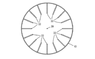
図6は、ドラムの展開図である。図6を参照して、第1開口部11から距離L1の位置の円周方向に、8個の第1突起部31が等間隔で配置される。図7は、第1開口部11から距離L1の位置のドラム10の断面図である。図6および図7を参照して、8個の第1突起部31は、ドラム10の側壁から回転軸39に向かって突出している。8個の第1突起部31を等間隔で配置しているので、互いに隣り合う2つの第1突起部31が配置される間隔を、パーツの最大長の3倍としている。   FIG. 6 is a development view of the drum. Referring to FIG. 6, eight first protrusions 31 are arranged at equal intervals in the circumferential direction at a distance L1 from first opening 11. FIG. 7 is a cross-sectional view of the drum 10 at a distance L1 from the first opening 11. 6 and 7, the eight first protrusions 31 protrude from the side wall of the drum 10 toward the rotation shaft 39. Since the eight first protrusions 31 are arranged at equal intervals, the interval between the two adjacent first protrusions 31 is set to three times the maximum length of the part.

また、第1開口部11から距離L2の位置の円周方向に、第1組を構成する16個の第2突起部33が等間隔で配置され、第1開口部11から距離L3の位置の円周方向に、第2組を構成する16個の第2突起部33が等間隔で配置され、第1開口部11から距離L4の位置の円周方向に、第3組を構成する16個の第2突起部33が等間隔で配置される。第1組〜第3組それぞれの16個の第2突起部33は、同じなので、ここでは第1組に含まれる16個の第2突起部33について説明する。図8は、第1開口部11から距離L2の位置のドラム10の断面図である。図6および図8を参照して、16個の第2突起部33は、ドラム10の側壁から回転軸39方向に突出している。16個の第2突起部33を等間隔で配置しているので、互いに隣り合う2つの第2突起部33が配置される間隔を、パーツの最大長の1.5倍としている。   In addition, sixteen second protrusions 33 constituting the first set are arranged at equal intervals in the circumferential direction at a distance L2 from the first opening 11, and at a distance L3 from the first opening 11. Sixteen second protrusions 33 constituting the second set are arranged at equal intervals in the circumferential direction, and sixteen constituting the third set in the circumferential direction at a distance L4 from the first opening 11. The second protrusions 33 are arranged at equal intervals. Since the 16 second protrusions 33 in the first to third groups are the same, here, the 16 second protrusions 33 included in the first set will be described. FIG. 8 is a cross-sectional view of the drum 10 at a distance L2 from the first opening 11. With reference to FIGS. 6 and 8, the 16 second protrusions 33 protrude from the side wall of the drum 10 in the direction of the rotation shaft 39. Since the 16 second protrusions 33 are arranged at equal intervals, the interval between the two adjacent second protrusions 33 is 1.5 times the maximum length of the part.

距離L2は、距離L1より長い。距離L2から距離L1を減算した差分G1は、第1組と第2組との間隔を示し、ドラム10の直径Dと、ドラム10の傾き角である支持角度θとにより定まる。例えば、差分G1は、Dtanθ以上とするのが好ましい。距離L3は、距離L2より長く、距離L3から距離L2を減算した差分G2は、第2組と第3組との間隔を示し、ドラム10の直径Dと、ドラム10の支持角度θとにより定まる。例えば、差分G2は、Dtanθ以上とするのが好ましい。同様に、距離L4は、距離L3より長く、距離L4から距離L3を減算した差分G3は、ドラム10の直径Dと、ドラム10の支持角度θとにより定まる。例えば、差分G3は、Dtanθ以上とするのが好ましい。   The distance L2 is longer than the distance L1. The difference G1 obtained by subtracting the distance L1 from the distance L2 indicates the interval between the first set and the second set, and is determined by the diameter D of the drum 10 and the support angle θ that is the tilt angle of the drum 10. For example, the difference G1 is preferably greater than or equal to Dtanθ. The distance L3 is longer than the distance L2, and the difference G2 obtained by subtracting the distance L2 from the distance L3 indicates an interval between the second set and the third set, and is determined by the diameter D of the drum 10 and the support angle θ of the drum 10. . For example, the difference G2 is preferably greater than or equal to Dtanθ. Similarly, the distance L4 is longer than the distance L3, and the difference G3 obtained by subtracting the distance L3 from the distance L4 is determined by the diameter D of the drum 10 and the support angle θ of the drum 10. For example, the difference G3 is preferably greater than or equal to Dtanθ.

さらに、第1開口部11から距離L7の位置の円周方向に、第1組を構成する8個の第3突起部35が等間隔で配置され、第1開口部11から距離L6の位置の円周方向に、第2組を構成する16個の第3突起部35が等間隔で配置され、第1開口部11から距離L5の位置の円周方向に、第3組を構成する8個の第3突起部35が等間隔で配置される。第1組〜第3組それぞれの8個の第3突起部35は、同じなので、ここでは第1組に含まれる8個の第3突起部35について説明する。図9は、第1開口部11から距離L7の位置のドラム10の断面図である。図6および図9を参照して、8個の第3突起部35は、ドラム10の側壁から回転軸39方向に突出している。8個の第3突起部35を等間隔で配置しているので、互いに隣り合う2つの第3突起部35が配置される間隔を、パーツの最大長の3倍としている。   Further, eight third protrusions 35 constituting the first set are arranged at equal intervals in the circumferential direction at a distance L7 from the first opening 11, and at a distance L6 from the first opening 11. Sixteen third protrusions 35 constituting the second set are arranged at equal intervals in the circumferential direction, and eight pieces constituting the third set are arranged in the circumferential direction at a distance L5 from the first opening 11. The third protrusions 35 are arranged at equal intervals. Since the eight third projecting portions 35 of each of the first to third sets are the same, the eight third projecting portions 35 included in the first set will be described here. FIG. 9 is a cross-sectional view of the drum 10 at a distance L7 from the first opening 11. With reference to FIGS. 6 and 9, the eight third protrusions 35 protrude from the side wall of the drum 10 in the direction of the rotation shaft 39. Since the eight third protrusions 35 are arranged at equal intervals, the interval at which the two third protrusions 35 adjacent to each other are arranged is three times the maximum length of the part.

距離L5は距離L1より短く、距離L6は距離L5より短く、距離L7は距離L6より短い。距離L6から距離L7を減算した値は、第1組と第2組との間隔を示し、距離L5から距離L6を減算した値は、第2組と第3組との間隔を示す。第1組と第2組との間隔、および第2組と第3組との間隔は、パーツの最大長より大きくするのが好ましい。さらに好ましくは、第1組と第2組との間隔、および第2組と第3組との間隔は、第2突起部33の第1組と第2組の間隔よりも大きくするのが好ましい。   The distance L5 is shorter than the distance L1, the distance L6 is shorter than the distance L5, and the distance L7 is shorter than the distance L6. A value obtained by subtracting the distance L7 from the distance L6 indicates an interval between the first set and the second set, and a value obtained by subtracting the distance L6 from the distance L5 indicates an interval between the second set and the third set. The interval between the first set and the second set, and the interval between the second set and the third set are preferably larger than the maximum length of the parts. More preferably, the interval between the first set and the second set, and the interval between the second set and the third set are preferably larger than the interval between the first set and the second set of the second protrusion 33. .

次に、本実施の形態における絡み部品分離装置1において、ドラム10に第1開口部11から複数のパーツを導入し、モーター21を駆動した場合の複数のパーツの状態について説明する。ここでは、モーター21は、一定の角速度で、同一方向に回転する。第1開口部11からドラム10内に導入された複数のパーツは、ドラム10の第1開口部11が第2開口部13よりも上方なので、重力によって第1開口部11から第2開口部13に向かう方向の力を受け付ける。このため、ドラム10の内壁は、パーツが滑りやすいように研磨されているのが好ましい。   Next, in the entangled component separating apparatus 1 according to the present embodiment, the state of the plurality of parts when a plurality of parts are introduced into the drum 10 from the first opening 11 and the motor 21 is driven will be described. Here, the motor 21 rotates in the same direction at a constant angular velocity. In the plurality of parts introduced into the drum 10 from the first opening 11, since the first opening 11 of the drum 10 is above the second opening 13, the first opening 11 to the second opening 13 are caused by gravity. Accepts the force in the direction toward. For this reason, it is preferable that the inner wall of the drum 10 is polished so that the parts are slippery.

第1開口部11から複数のパーツをドラム10に導入し、モーター21を駆動した段階で、複数のパーツのうち4つ以上のパーツが絡まった多数パーツ群は、8個の第1突起部31のいずれかによって8個の第1突起部31よりも第2開口部13側への移動が制限される。また、複数のパーツのうち3つ以下のパーツが絡まった少数パーツ群は、8個の第1突起部31の間をすり抜けて8個の第1突起部31よりも第2開口部13側へ移動することが可能である。また、複数のパーツのうち他のパーツと絡み合っていない単独のパーツは、8個の第1突起部31の間をすり抜けて8つの第1突起部31よりも第2開口部13側へ移動することが可能である。   At the stage where a plurality of parts are introduced into the drum 10 from the first opening 11 and the motor 21 is driven, a multipart group in which four or more parts of the plurality of parts are entangled with each other includes eight first protrusions 31. Any of the above restricts movement of the eight first protrusions 31 toward the second opening 13. Further, a minority part group in which three or less parts are entangled among a plurality of parts passes through the eight first protrusions 31 and is closer to the second opening 13 than the eight first protrusions 31. It is possible to move. A single part that is not intertwined with other parts among the plurality of parts passes through the eight first protrusions 31 and moves to the second opening 13 side rather than the eight first protrusions 31. It is possible.

本実施の形態おいては、8個の第1突起部31それぞれの端部の間隔の最小値は、パーツの最大長より大きい。このため、1つのパーツが8個の第1突起部31の2つ以上に同時に絡まることがなく、他のパーツと絡まない単独のパーツが、8個の第1突起部31のいずれとも絡まずに、第2開口部13側に移動する確率を高めることができる。   In the present embodiment, the minimum value of the distance between the end portions of each of the eight first protrusions 31 is larger than the maximum length of the part. For this reason, one part is not entangled with two or more of the eight first protrusions 31 at the same time, and a single part that does not entangle with other parts does not entangle with any of the eight first protrusions 31. Moreover, the probability of moving to the second opening 13 side can be increased.

また、多数パーツ群が、8個の第1突起部31の2以上に同時に絡まる場合がある。多数パーツ群が、8個の第1突起部31のうちで絡み合う第1突起部31の数が多くなると、ドラム10の回転中におけるパーツ群の移動が、絡み合った第1突起部31の数と同じ数の方向で規制される。しかしながら、多数パーツ群に含まれる複数のパーツのうち、8個の第1突起部31のいずれかと絡み合う2以上のパーツはすべて異なる。このため、多数パーツ群は、ドラム10の回転に伴って、多数パーツ群を構成する複数のパーツ同士の絡み方が変化し、多数パーツ群の形状が変化する。具体的には、多数パーツ群のうちには、ドラム10の回転に伴って、それまで絡んでいたパーツとの絡みが解消されてパーツ多数パーツ群から離脱するパーツ、それまで絡んでいなかったパーツと絡むパーツ、それまで絡んでいた第1突起部31との絡みが解消されるパーツ、新たに第1突起部31とからむパーツ等が存在する。このため、多数パーツ群は、ドラム10が回転するに伴って、8個の第1突起部31のうちで絡み合っていた第1突起部との絡みが解消される場合もあり、8個の第1突起部31のうちで絡み合っていなかった第1突起部との絡む場合もある。   In addition, a large number of parts groups may be simultaneously entangled with two or more of the eight first protrusions 31. When the number of the first protrusions 31 intertwined among the eight first protrusions 31 increases, the movement of the parts group during the rotation of the drum 10 is the number of the first protrusions 31 intertwined. Regulated in the same number of directions. However, two or more parts intertwined with any of the eight first protrusions 31 among the plurality of parts included in the multiple parts group are all different. For this reason, in the multi-part group, as the drum 10 rotates, the entanglement method of the plurality of parts constituting the multi-part group changes, and the shape of the multi-part group changes. Specifically, among the many parts group, as the drum 10 rotates, the part that has been entangled with the part that has been entangled until then is removed, and the part that has left the part part group has not been entangled until then. There are parts that are entangled with the parts, parts that are entangled with the first protrusions 31 that have been entangled so far, parts that are newly entangled with the first protrusions 31, and the like. For this reason, in the multiple parts group, as the drum 10 rotates, the entanglement with the first protrusions entangled among the eight first protrusions 31 may be eliminated, and the eight first In some cases, the first protrusion 31 may be entangled with the first protrusion that was not entangled.

このため、多数パーツ群は、ドラム10の回転に伴って、8個の第1突起部31の2以上と絡みながら形状を変化させるので、多数パーツ群から離脱するパーツが発生する。多数パーツ群から離脱するパーツのうち少数パーツ群および他のパーツと絡まない単独のパーツは、8個の第1突起部31の間をすり抜けて8つの第1突起部31よりも第2開口部13側への移動が可能である。   For this reason, the multi-part group changes its shape while being entangled with two or more of the eight first protrusions 31 as the drum 10 rotates, so that a part that detaches from the multi-part group is generated. A single part that is not entangled with a small number of parts and other parts out of parts that detach from the large number of parts passes through between the eight first protrusions 31 and is a second opening than the eight first protrusions 31. Movement to the 13 side is possible.

8個の第1突起部31のいずれかに絡まった多数パーツ群は、第1組〜第3組それぞれに属する8個の第3突起部35の少なくとも1つと絡まる。第1組〜第3組それぞれに属する8個の第3突起部35は、8個の第1突起部31のいずれかに絡まった多数パーツ群の全体を、ドラム10の回転に伴って回転させる。これにより、多数パーツ群のうちから分離した単独のパーツ、または少数パーツ群が、第1組〜第3組それぞれに属する8個の第3突起部35および8個の第1突起部31の間をすり抜けて8個の第1突起部31よりも第2開口部13側へ移動することが可能である。   The multiple parts group entangled with any of the eight first protrusions 31 is entangled with at least one of the eight third protrusions 35 belonging to each of the first to third groups. The eight third protrusions 35 belonging to each of the first to third groups rotate the whole of a large number of parts entangled with any of the eight first protrusions 31 as the drum 10 rotates. . As a result, a single part or a small number of parts separated from the large number of parts group is between the eight third protrusions 35 and the eight first protrusions 31 belonging to the first to third groups. It is possible to pass through the first opening 31 and move toward the second opening 13 rather than the eight first protrusions 31.

ドラム10が第1組〜第3組それぞれに属する8個の第3突起部35を有しない場合、8個の第1突起部31のいずれかに絡まった多数パーツ群は、8個の第1突起部31のいずれかに絡まった部分が第1突起部31から力を受けるが、8個の第1突起部31のいずれとも絡まっていない部分は、それが絡まるパーツから力を受けて回転する。このため、8個の第1突起部31のいずれかに絡まった部分が、第1突起部31から受ける力が、順に他のパーツに伝達されて、多数パーツ群全体が回転する。この際に、互いに絡み合う複数のパーツ間における絡みが強固になってしまう場合がある。   When the drum 10 does not have the eight third protrusions 35 belonging to the first to third sets, the multiple parts group entangled with any of the eight first protrusions 31 is the eight first protrusions. A portion entangled with one of the protrusions 31 receives a force from the first protrusion 31, but a portion that is not entangled with any of the eight first protrusions 31 receives a force from the part with which it entangles and rotates. . For this reason, the force which the part entangled in any of the eight 1st projection parts 31 receives from the 1st projection part 31 is transmitted to another part in order, and the whole many parts group rotates. At this time, the entanglement between a plurality of parts entangled with each other may become strong.

ドラム10が第1組〜第3組それぞれに属する8個の第3突起部35を有する場合は、8個の第1突起部31のいずれかに絡まった多数パーツ群の全体を、ドラム10の回転に伴って回転させるので、多数パーツ群を構成する複数のパーツ間の絡みの力が強くなるのを防止して、多数パーツ群を構成する複数のパーツが多数パーツ群から分離しやすくすることができる。   When the drum 10 has eight third protrusions 35 belonging to each of the first to third sets, the entire multiple parts group entangled with any of the eight first protrusions 31 is Since it is rotated with rotation, it prevents the entanglement force between multiple parts that make up the multiple parts group from becoming strong, and makes it easy to separate multiple parts that make up the multiple parts group from the multiple parts group Can do.

第1開口部11に投入された複数のパーツのうち、8つの第1突起部31の間を通過して、第1開口部11からの距離L2以上の位置まで到達するパーツは、単独のパーツまたは少数パーツ群である。単独のパーツは、ドラム10が傾いているので、第1〜第3組それぞれの16個の第2突起部33の隙間を通って、重力によって第2開口部13まで移動してドラム10から排出される。少数パーツ群は、第1組を構成する16個の第2突起部33のいずれかによって、第2開口部13への移動が規制される。少数パーツ群は、第1組を構成する16個の第2突起部33のいずれかに絡まり、第2突起部33に絡まったままドラム10の回転によって上方に持ち上げられ、さらに、その後重力によって第2突起部33との絡まりが解消される時点で、下方に落下する。少数パーツ群は、下方に落下するとドラム10の内壁に衝突するので、その外力によって絡まりが解消される場合がある。少数パーツ群を構成する2以上のパーツのうち絡まりが解消された単独のパーツは、重力によって第2開口部13まで移動することが可能である。   Of the plurality of parts put into the first opening 11, a part that passes between the eight first protrusions 31 and reaches a position equal to or longer than the distance L <b> 2 from the first opening 11 is a single part. Or a few parts group. Since the drum 10 is inclined, the single part moves through the gap between the 16 second protrusions 33 of each of the first to third sets, and moves to the second opening 13 by gravity to be discharged from the drum 10. Is done. The minority part group is restricted from moving to the second opening 13 by any one of the 16 second protrusions 33 constituting the first set. The minority part group is entangled with one of the 16 second projecting portions 33 constituting the first set, and is lifted upward by the rotation of the drum 10 while being entangled with the second projecting portion 33. When the entanglement with the two projecting portions 33 is eliminated, it falls downward. Since the minority parts group collides with the inner wall of the drum 10 when dropped, the entanglement may be eliminated by the external force. Of the two or more parts constituting the small number of parts group, a single part in which the entanglement is eliminated can move to the second opening 13 by gravity.

一方、少数パーツ群が落下する位置は、距離L3から距離L2を減算した差分G2がDtanθ以上なので、第2組を構成する16個の第2突起部33のいずれかに絡まる。このため、少数パーツ群のうち他のパーツとの絡まりが解消されていない複数のパーツを構成する新たな少数パーツ群は、第2組を構成する16個の第2突起部33のいずれかにに絡まり、ドラム10の回転によって上方に持ち上げられ、さらに、その後重力によって第2突起部33との絡まりが解消される時点で、下方に落下する。少数パーツ群を構成する2以上のパーツのうち絡まりが解消された単独のパーツは、重力によって第2開口部13まで移動することが可能であるが、少数パーツ群のうち他のパーツとの絡まりが解消されていない複数のパーツを構成する新たな少数パーツ群は、第3組を構成する16個の第2突起部33のいずれかにに絡まり、ドラム10の回転によって上方に持ち上げられ、さらに、その後重力によって第2突起部33との絡まりが解消される時点で、下方に落下する。このように、少数パーツ群を、3回落下させるので、高い確率で少数パーツ群を単独のパーツに分離することができる。なお、ここでは、16個の第2突起部33の組を、3組備える例を説明したが、パーツの形状、材質等によって、組数を変更するようにしてもよい。組数を増加することにより、単独のパーツに分離できる確率を高くすることができる。また、単独のパーツに分離できる確率が所定の値となる場合には、1組であってもよい。   On the other hand, since the difference G2 obtained by subtracting the distance L2 from the distance L3 is equal to or greater than Dtanθ, the position where the minority part group falls is entangled with any of the 16 second protrusions 33 constituting the second set. For this reason, a new minority part group that constitutes a plurality of parts that have not been entangled with other parts in the minority part group is one of the 16 second protrusions 33 that constitute the second set. Entangled and lifted upward by the rotation of the drum 10, and then falls downward when the entanglement with the second protrusion 33 is eliminated by gravity. A single part in which the entanglement is eliminated among two or more parts constituting the minority part group can move to the second opening 13 by gravity, but the entanglement with other parts in the minority part group A new minority part group that constitutes a plurality of parts that has not been solved is entangled with one of the 16 second protrusions 33 constituting the third group, and is lifted upward by the rotation of the drum 10. Then, when the entanglement with the second protrusion 33 is eliminated by gravity, it falls downward. Thus, since the minority part group is dropped three times, the minority part group can be separated into a single part with high probability. In addition, although the example provided with 3 sets of 16 2nd projection parts 33 was demonstrated here, you may make it change the number of sets according to the shape, material, etc. of parts. By increasing the number of sets, it is possible to increase the probability that it can be separated into single parts. Moreover, when the probability that it can be separated into individual parts becomes a predetermined value, one set may be used.

以上説明したように、本実施の形態における部品分離装置1は、パーツの導入口となる第1開口部11と、パーツの排出口となる第2開口部13とを含む円筒状のドラム10と、ドラム10の側壁からドラムの内側に突出し、ドラムの円周方向に互いに間隔をおいて配置される複数の第1突起部31と、水平方向から支持角度θだけ傾いた回転軸39を中心にドラム10を回転させる駆動機構20と、を備える。このため、第1開口部11に導入されたパーツのうち他のパーツと絡み合った複数のパーツからなるパーツ群は、複数の第1突起部31のいずれかに絡まるので、パーツ群が第2開口部13に移動しないようにすることができる。また、複数の第1突起部31のいずれかに絡まったパーツ群はドラムの回転によって上方に持ち上げられた後に重力によって落下する。このため、落下によって、パーツ群に含まれる複数のパーツのうちには他のパーツとの絡まりが解除される場合がある。このため、互いに絡まったパーツを分離することができる。   As described above, the component separating apparatus 1 according to the present embodiment includes the cylindrical drum 10 including the first opening 11 serving as a part introduction port and the second opening 13 serving as a part discharge port. A plurality of first protrusions 31 that protrude from the side wall of the drum 10 to the inside of the drum and are spaced apart from each other in the circumferential direction of the drum, and a rotation shaft 39 that is inclined by a support angle θ from the horizontal direction. And a drive mechanism 20 that rotates the drum 10. For this reason, a part group consisting of a plurality of parts intertwined with other parts among the parts introduced into the first opening 11 is entangled with one of the plurality of first protrusions 31, so that the part group is the second opening. The movement to the part 13 can be prevented. Further, a part group entangled with any of the plurality of first protrusions 31 is lifted upward by the rotation of the drum and then falls by gravity. For this reason, entanglement with other parts may be canceled among the plurality of parts included in the part group due to falling. For this reason, parts entangled with each other can be separated.

また、ドラム10は、複数の第1突起部31より第2開口部13側で円周方向に互いに間隔をおいて配置される複数の第2突起部33を含み、複数の第1突起部31の径方向の長さは、複数の第2突起部33の径方向の長さよりも長い。このため、複数の第1突起部31によって、複数の第2突起部33よりも絡まったパーツの数の多いパーツ群を分離し、複数の第2突起部33によって、複数の第1突起部31によって絡まったパーツ数が減られたパーツ群を分離することができる。そのため、段階的に絡まったパーツの数を減らすので、効率よく絡まったパーツを分離することができる。   The drum 10 includes a plurality of second protrusions 33 that are spaced apart from each other in the circumferential direction on the second opening 13 side from the plurality of first protrusions 31. The length in the radial direction is longer than the length in the radial direction of the plurality of second protrusions 33. For this reason, the plurality of first protrusions 31 separates a group of parts having a larger number of parts than the plurality of second protrusions 33, and the plurality of second protrusions 33 separates the plurality of first protrusions 31. It is possible to separate parts groups in which the number of parts entangled with each other is reduced. For this reason, the number of entangled parts is reduced step by step, so that the entangled parts can be separated efficiently.

また、複数の第1突起部31のそれぞれの複数の端部間の距離の最小値は、パーツの最大値より大きいので、1つのパーツが複数の第1突起部31の2以上に同時に絡まないようにすることができ、ドラム10の回転にともなってパーツが動かなくなるのを防止することができる。   Moreover, since the minimum value of the distance between the plurality of end portions of each of the plurality of first protrusions 31 is larger than the maximum value of the parts, one part does not simultaneously entangle with two or more of the plurality of first protrusions 31. It is possible to prevent the parts from moving as the drum 10 rotates.

また、複数の第1突起部31それぞれがドラムの内壁に配置される間隔は、パーツの最大長より大きいので、他のパーツと絡まない単独のパーツが複数の第1突起部31の間をすり抜けることが可能となり、単独のパーツを第2開口部13から排出することができる。   In addition, since the interval at which each of the plurality of first protrusions 31 is arranged on the inner wall of the drum is larger than the maximum length of the part, a single part that does not entangle with other parts slips between the plurality of first protrusions 31. And a single part can be discharged from the second opening 13.

また、ドラム10は、複数の第1突起部31より第1開口部11側で円周方向に互いに間隔をおいて配置される複数の第3突起部35を、さらに含む。このため、互いに絡まった複数のパーツからなるパーツ群が複数の第1突起部31のいずれかに絡まる場合、パーツ群が複数の第3突起部35にも絡まるので、ドラム10の回転に伴ってパーツ群を回転させることができる。これにより、パーツ群を回転させている間に、互いに絡まった複数のパーツを分離することができる。   In addition, the drum 10 further includes a plurality of third protrusions 35 that are spaced apart from each other in the circumferential direction on the first opening 11 side from the plurality of first protrusions 31. For this reason, when a part group composed of a plurality of parts entangled with each other is entangled with any of the plurality of first protrusions 31, the part group is also entangled with the plurality of third protrusions 35. Parts can be rotated. Thereby, a plurality of parts entangled with each other can be separated while rotating the parts group.

なお、本実施の形態においては、8個の第1突起部31を円周方向に等間隔で配置するようにしたが、等間隔でなくてもよい。同様に、第1組〜第3組それぞれを構成する16個の第2突起部33を円周方向に等間隔で配置するようにしたが、等間隔でなくてもよい。さらに、第1組〜第3組それぞれを構成する8個の第3突起部35を、円周方向に等間隔に配置するようにしたが、等間隔でなくてもよい。   In the present embodiment, the eight first protrusions 31 are arranged at equal intervals in the circumferential direction, but may not be equal intervals. Similarly, the 16 second protrusions 33 constituting each of the first to third sets are arranged at equal intervals in the circumferential direction, but may not be equal intervals. Further, the eight third projecting portions 35 constituting each of the first to third sets are arranged at equal intervals in the circumferential direction, but may not be equal intervals.

<第1の変形例>
上述した実施の形態における絡みパーツ分離装置1は、ドラム10が、8個の第1突起部31よりも第1開口部13側の円周方向に所定の間隔で配置される8個の第3突起部35の組を3組含む場合を例に説明した。第1の変形例における絡みパーツ分離装置1は、複数の第3突起部35が、8個の第1突起部31よりも第1開口部13側の回転軸39と並行な方向に所定の間隔で配置されるようにしたものである。この場合、互いに隣り合う2つの第3突起部35が配置される間隔は、任意に定めることができる。また、複数の第3突起部35の長さは、任意に定めることができる。
<First Modification>
In the entangled parts separating device 1 according to the above-described embodiment, the drums 10 are arranged in the eight third protrusions arranged at predetermined intervals in the circumferential direction closer to the first opening 13 than the eight first protrusions 31. The case where three sets of the protrusions 35 are included has been described as an example. In the entangled parts separating device 1 in the first modified example, the plurality of third projecting portions 35 have a predetermined interval in a direction parallel to the rotary shaft 39 closer to the first opening 13 than the eight first projecting portions 31. It is arranged at. In this case, the interval at which the two third protrusions 35 adjacent to each other are arranged can be arbitrarily determined. The lengths of the plurality of third protrusions 35 can be arbitrarily determined.

ここでは、第1の変形例における絡みパーツ分離装置1において、ドラム10が、8個の第1突起部31を有し、16個の第2突起部33を1組とした3組を有し、3個の第3突起部35を有する場合を例に説明する。8個の第1突起部31、第1組〜第3組それぞれに属する16個の第2突起部33については、上述した絡みパーツ分離装置1と同じなので、ここでは説明を繰り返さない。   Here, in the entangled parts separating device 1 in the first modification, the drum 10 has three sets of eight first protrusions 31 and sixteen second protrusions 33 as one set. A case where there are three third protrusions 35 will be described as an example. Since the eight first protrusions 31 and the 16 second protrusions 33 belonging to each of the first to third groups are the same as those of the entangled parts separating device 1 described above, description thereof will not be repeated here.

図10は、第1の変形例におけるドラムの展開図である。図10を参照して、3個の第3突起部35は、8個の第1突起部31よりも第1開口部13側の回転軸39と並行な方向に所定の間隔で配置される。   FIG. 10 is a development view of the drum in the first modification. Referring to FIG. 10, the three third protrusions 35 are arranged at a predetermined interval in a direction parallel to the rotation shaft 39 on the first opening 13 side than the eight first protrusions 31.

次に、第1の変形例における絡み部品分離装置1において、ドラム10に第1開口部11から複数のパーツを導入し、モーター21を駆動した場合の複数のパーツの状態について説明する。第1開口部11から複数のパーツをドラム10に導入し、モーター21を駆動した段階で、複数のパーツのうち4つ以上のパーツが絡まった多数パーツ群は、8個の第1突起部31のいずれかによって8個の第1突起部31よりも第2開口部13側への移動が制限される。   Next, in the entangled component separating apparatus 1 according to the first modification, the state of the plurality of parts when a plurality of parts are introduced into the drum 10 from the first opening 11 and the motor 21 is driven will be described. At the stage where a plurality of parts are introduced into the drum 10 from the first opening 11 and the motor 21 is driven, a multipart group in which four or more parts of the plurality of parts are entangled with each other includes eight first protrusions 31. Any of the above restricts movement of the eight first protrusions 31 toward the second opening 13.

3個の第3突起部35は、8個の第1突起部31よりも第1開口部11側に位置する多数パーツ群を、ドラム10の回転に伴って、上方に移動させる。多数パーツ群が上方へ移動するに伴って、多数パーツ群は、重力によって第3突起部35との絡みが解消され、下方に落下する。多数パーツ群は、下方に落下するとドラム10の内壁に衝突するので、その外力によって絡まりが解消される場合がある。多数パーツ群を構成する複数のパーツのうち絡まりが解消された少数パーツ群または単独のパーツは、次に第3突起部35と絡む前に、8個の第1突起部31の間をすり抜けて8個の第1突起部31よりも第2開口部13側へ移動することが可能である。このように、第3突起部35がドラム10の回転に伴って多数パーツ群を上方へ移動させることにより、多数パーツ群が上方への移動を開始してから落下するまでの間の期間を、少数パーツ群または単独のパーツが、8個の第1突起部31よりも第2開口部13側へ移動する時間として確保することができる。3個の第3突起部35の長さは、多数パーツ群が上方への移動を開始してから落下するまでの間の期間によって定まる。3個の第3突起部35の長さが長いほど、多数パーツ群と絡み合っている時間を長くなるので、多数パーツ群が上方への移動を開始してから落下するまでの間の期間が長くなる。   The three third projecting portions 35 move the multiple parts group located closer to the first opening 11 side than the eight first projecting portions 31 as the drum 10 rotates. As the multiple parts group moves upward, the multiple parts group is entangled with the third protrusion 35 due to gravity and falls downward. When the multiple parts group falls downward, it collides with the inner wall of the drum 10, so that the entanglement may be eliminated by the external force. Among the plurality of parts constituting the multiple parts group, the minority part group or the single part in which the entanglement has been eliminated passes between the eight first protrusions 31 before the entanglement with the third protrusion 35 next. The eight first protrusions 31 can move to the second opening 13 side. In this way, the third protrusion 35 moves the multiple parts group upward as the drum 10 rotates, so that the period from when the multiple parts group starts to move upward until it falls, It can be ensured as a time for a small number of parts group or a single part to move from the eight first protrusions 31 to the second opening 13 side. The lengths of the three third protrusions 35 are determined by the period from when the multiple parts group starts to move upward until it falls. The longer the length of the three third protrusions 35, the longer the time of intertwining with the large number of parts group, so the period from when the large number of parts group starts moving upward until it falls is longer. Become.

第1の変形例における絡み部品分離装置1において、ドラム10は、複数の第1突起部31より第1開口部11側で回転軸39方向に互いに間隔をおいて配置される複数の第3突起部35を、さらに含む。このため、互いに絡まった複数のパーツからなるパーツ群が複数の第1突起部31のいずれかに絡まる場合、パーツ群が複数の第3突起部35にも絡まるので、ドラム10の回転に伴ってパーツ群を上方に持ち上げた後に重力によって落下させることができる。これにより、互いに絡まった複数のパーツを分離することができる。また、パーツ群を上方に持ち上げてから落下させるまでの期間を、複数の第1突起部31より第1開口部11側にある単独のパーツが複数の第1突起部31よりも第2開口部13側に移動するための時間として確保するので、単独のパーツがパーツ群と絡み合うのを防止することができる。   In the entangled component separation device 1 according to the first modification, the drum 10 includes a plurality of third protrusions that are arranged at a distance from each other in the direction of the rotation shaft 39 on the first opening 11 side of the plurality of first protrusions 31. The unit 35 is further included. For this reason, when a part group composed of a plurality of parts entangled with each other is entangled with any of the plurality of first protrusions 31, the part group is also entangled with the plurality of third protrusions 35. The parts can be dropped by gravity after being lifted upward. Thereby, a plurality of parts entangled with each other can be separated. In addition, the period from when the parts group is lifted upward until it is dropped, the single part located on the first opening 11 side from the plurality of first protrusions 31 is the second opening than the plurality of first protrusions 31. Since the time for moving to the 13th side is secured, it is possible to prevent a single part from being entangled with a part group.

<第2の変形例>
上述した実施の形態における第1組〜第3組それぞれに含まれる8個の第3突起部35の長さをすべて同じにするのではなく、特定の第3突起部35を他の複数の第3突起部35よりも長くするようにしてもよい。例えば、第1組に含まれる8個の第3突起部35のうち1つを特定の第3突起部35とし、第2組に含まれる8個の第3突起部35のうち第1組の特定の第3突起部35との距離が最も近い1つを特定の第3突起部35とし、第3組に含まれる8個の第3突起部35のうち第2組の特定の第3突起部35との距離が最も近い1つを特定の第3突起部35とする。これにより、3つの特定の第3突起部35が、多数パーツ群を上方に持ち上げて落下させることによりパーツを分離させることができるとともに、他の複数の第3突起部35が、多数パーツ群を回転させることにより、パーツを分離させることができる。
<Second Modification>
Rather than making the lengths of the eight third protrusions 35 included in each of the first to third sets in the above-described embodiment all the same, the specific third protrusion 35 is replaced with a plurality of other third protrusions 35. The length may be longer than the three protrusions 35. For example, one of the eight third protrusions 35 included in the first set is designated as a specific third protrusion 35, and the first set of eight third protrusions 35 included in the second set One closest to the specific third protrusion 35 is defined as a specific third protrusion 35, and the second set of specific third protrusions among the eight third protrusions 35 included in the third set. One with the shortest distance to the part 35 is defined as a specific third protrusion 35. As a result, the three specific third projecting portions 35 can separate the parts by lifting and dropping a large number of parts groups upward, and the other plurality of third projecting portions 35 By rotating, parts can be separated.

<第3の変形例>
上述した実施の形態においては、複数の第1突起部31、複数の第2突起部33および複数の第3突起部35それぞれは、ドラム10の内壁から垂直に突出する場合を例に説明したが、複数の第1突起部31、複数の第2突起部33および複数の第3突起部35それぞれは、ドラム10の内壁から突出すればよい。好ましくは、複数の第2突起部33および複数の第3突起部35それぞれは、回転軸39に向かって突出する。例えば、複数の第1突起部31、複数の第2突起部33および複数の第3突起部35それぞれは、第1開口部11側に傾いて突出するようにしてもよいし、第2開口部13側に傾いて突出するようにしてもよい。この場合において、複数の第1突起部31それぞれを第2開口部13に投影した像の径方向の長さは、複数の第2突起部33それぞれを第2開口部13に投影した像の径方向の長さよりも長い。
<Third Modification>
In the above-described embodiment, the case where each of the plurality of first protrusions 31, the plurality of second protrusions 33, and the plurality of third protrusions 35 protrudes vertically from the inner wall of the drum 10 has been described as an example. Each of the plurality of first protrusions 31, the plurality of second protrusions 33, and the plurality of third protrusions 35 may protrude from the inner wall of the drum 10. Preferably, each of the plurality of second protrusions 33 and the plurality of third protrusions 35 protrudes toward the rotation shaft 39. For example, each of the plurality of first protrusions 31, the plurality of second protrusions 33, and the plurality of third protrusions 35 may be inclined and protrude toward the first opening 11, or the second opening You may make it protrude inclining to 13 side. In this case, the length in the radial direction of the image in which each of the plurality of first protrusions 31 is projected on the second opening 13 is the diameter of the image in which each of the plurality of second protrusions 33 is projected on the second opening 13. Longer than the direction length.

<第4の変形例>
上述した実施の形態における絡み部品分離装置1は、8個の第1突起部31を、第1開口部11から距離L1の円周方向に所定の間隔で配置するようにしたが、第1開口部11から距離L1から距離L5までの円筒部分に、円周方向に所定の間隔で配置する配置するようにしてもよい。この場合には、8個の第1突起部31を、千鳥格子状に配置するのが好ましい。具体的には、第1開口部11から距離L1の位置に配置された第1突起部31に対して、それと隣り合う2つの第1突起部31が第1開口部11から距離L1よりも所定の長さだけ長い距離L8の位置に配置され、第1開口部11から距離L8の位置に配置された第1突起部31に対して、それと隣り合う2つの第1突起部31が第1開口部11から距離L1の位置に配置される。また、8個の第1突起部31が配置される間隔は、同じでなくてもよい。
<Fourth Modification>
In the entangled component separation device 1 in the above-described embodiment, the eight first protrusions 31 are arranged at predetermined intervals in the circumferential direction at a distance L1 from the first opening 11, but the first opening You may make it arrange | position with the predetermined | prescribed space | interval in the circumferential direction in the cylindrical part from the part 11 to the distance L1 to the distance L5. In this case, it is preferable to arrange the eight first protrusions 31 in a staggered pattern. Specifically, with respect to the first protrusion 31 disposed at a distance L1 from the first opening 11, two adjacent first protrusions 31 are more predetermined than the distance L1 from the first opening 11. Two first protrusions 31 adjacent to the first protrusion 31 disposed at a distance L8 from the first opening 11 are disposed at the position of the distance L8 that is longer than the first opening 11 by the first opening 11. It is arranged at a position of a distance L1 from the part 11. The intervals at which the eight first protrusions 31 are arranged may not be the same.

同様に、第1組〜第3組それぞれを構成する16個の第2突起部33を、円筒部分に円周方向に所定の間隔で配置するようにしてもよい。また、8個の第1突起部31を、第1開口部11から距離L1の円周方向に所定の間隔で配置し、第1組〜第3組それぞれを構成する16個の第2突起部33を、円筒部分に円周方向に所定の間隔で配置するようにしてもよい。また、16個の第2突起部33が配置される間隔は、同じでなくてもよい。   Similarly, the 16 second protrusions 33 constituting each of the first to third sets may be arranged at predetermined intervals in the circumferential direction on the cylindrical portion. In addition, eight first protrusions 31 are arranged at a predetermined interval in the circumferential direction at a distance L1 from the first opening 11, and 16 second protrusions constituting each of the first to third sets. 33 may be arranged at predetermined intervals in the circumferential direction in the cylindrical portion. Further, the intervals at which the 16 second protrusions 33 are arranged may not be the same.

同様に、第1組〜第3組それぞれを構成する8個の第3突起部35を、円筒部分に円周方向に所定の間隔で配置するようにしてもよい。また、8個の第1突起部31を、第1開口部11から距離L1の円周方向に所定の間隔で配置し、第1組〜第3組それぞれを構成する8個の第3突起部35を、円筒部分に円周方向に所定の間隔で配置するようにしてもよい。また、8個の第3突起部35が配置される間隔は、同じでなくてもよい。   Similarly, the eight third projecting portions 35 constituting each of the first to third sets may be arranged at predetermined intervals in the circumferential direction on the cylindrical portion. In addition, eight first protrusions 31 are arranged at predetermined intervals in the circumferential direction at a distance L1 from the first opening 11, and the eight third protrusions constituting each of the first to third sets. 35 may be arranged in the cylindrical portion at a predetermined interval in the circumferential direction. Further, the intervals at which the eight third protrusions 35 are arranged may not be the same.

<第5の変形例>
上述した実施の形態における絡み部品分離装置1は、ドラム10の回転軸39が、ドラム10の側壁と並行で、ドラム10の側壁の内側に位置し、ドラム10の側壁からの距離が一定とする場合を例に説明した。
<Fifth Modification>
In the entangled component separating device 1 in the above-described embodiment, the rotation shaft 39 of the drum 10 is positioned inside the side wall of the drum 10 in parallel with the side wall of the drum 10, and the distance from the side wall of the drum 10 is constant. The case has been described as an example.

ドラム10の回転軸39を、ドラム10の側壁と並行で、ドラム10の側壁の外側に位置するようにしてもよい。また、ドラム10の回転軸39を、ドラム10の側壁と並行でない軸としてもよい。   The rotating shaft 39 of the drum 10 may be positioned outside the side wall of the drum 10 in parallel with the side wall of the drum 10. Further, the rotating shaft 39 of the drum 10 may be an axis that is not parallel to the side wall of the drum 10.

今回開示された実施の形態はすべての点で例示であって制限的なものではないと考えられるべきである。本発明の範囲は上記した説明ではなくて特許請求の範囲によって示され、特許請求の範囲と均等の意味および範囲内でのすべての変更が含まれることが意図される。   The embodiment disclosed this time should be considered as illustrative in all points and not restrictive. The scope of the present invention is defined by the terms of the claims, rather than the description above, and is intended to include any modifications within the scope and meaning equivalent to the terms of the claims.

<付記>
(1) 前記複数の第1突起部は、前記ドラムの前記第1開口部から所定の距離の円周方向に互いに間隔をおいて配置される、請求項2〜8のいずれかに記載の絡み部品分離装置。
(2) 前記複数の第1突起部は、前記ドラムの前記第1開口部からの所定の距離の円筒状の領域の円周方向に互いに間隔を置いて配置される、請求項2〜8のいずれかに記載の絡み部品分離装置。
(3) 前記回転軸は、前記ドラムの側壁と並行である、請求項1〜8のいずれかに記載の絡み部品分離装置。
(4) 前記回転軸は、前記ドラムの側壁の内側に位置する、(3)に記載の絡み部品分離装置。
(5) 前記回転軸は、前記ドラムの側壁からの距離が一定である、(4)に記載の絡み部品分離装置。
<Appendix>
(1) The entanglement according to any one of claims 2 to 8, wherein the plurality of first protrusions are spaced apart from each other in a circumferential direction at a predetermined distance from the first opening of the drum. Parts separator.
(2) The plurality of first protrusions are arranged at intervals in a circumferential direction of a cylindrical region having a predetermined distance from the first opening of the drum. The entangled component separator according to any one of the above.
(3) The entangled component separation device according to any one of claims 1 to 8, wherein the rotation shaft is parallel to a side wall of the drum.
(4) The entangled component separation device according to (3), wherein the rotation shaft is located inside a side wall of the drum.
(5) The entangled component separation device according to (4), wherein the rotation shaft has a constant distance from a side wall of the drum.

1 絡み部品分離装置、10 ドラム、11 第1開口部、13 第2開口部、15 フランジ、20 駆動機構、21 モーター、22 プーリー、23 駆動ベルト、24 第1ローラ、25 第2ローラ、26 ストッパー、26A 軸、26B ローラ、29 基台、31 第1突起部、33 第2突起部、35 第3突起部、39 回転軸。   DESCRIPTION OF SYMBOLS 1 Tangled component separation apparatus, 10 drum, 11 1st opening part, 13 2nd opening part, 15 flange, 20 drive mechanism, 21 motor, 22 pulley, 23 drive belt, 24 1st roller, 25 2nd roller, 26 stopper , 26A shaft, 26B roller, 29 base, 31 first protrusion, 33 second protrusion, 35 third protrusion, 39 rotation axis.

Claims (5)

パーツの導入口となる第1開口部と、前記パーツの排出口となる第2開口部とを含む円筒状のドラムと、
前記ドラムの側壁から前記ドラムの内側に突出する複数の突起部と、
前記第1開口部の中心が前記第2開口部の中心より高い状態で、重力方向と交わる回転軸を中心に前記ドラムを回転させる駆動機構と、を備えた絡み部品分離装置。
A cylindrical drum including a first opening serving as an introduction port for parts and a second opening serving as a discharge port for the parts;
A plurality of protrusions protruding from the side wall of the drum to the inside of the drum;
And a drive mechanism that rotates the drum about a rotation axis that intersects the direction of gravity in a state where the center of the first opening is higher than the center of the second opening.
前記パーツが前記ドラムの回転に伴って前記複数の突起部の2以上に同時に絡むことがないように、前記複数の突起部の端部間の距離が設定される、請求項1に記載の絡み部品分離装置。   2. The entanglement according to claim 1, wherein a distance between the end portions of the plurality of protrusions is set so that the parts do not simultaneously entangle with two or more of the plurality of protrusions as the drum rotates. Parts separator. 前記パーツの複数が前記ドラムに前記第1開口部から投入された状態で前記複数のパーツのうち他のパーツと絡む複数のパーツからなるパーツ群が前記ドラムの回転に伴って前記複数の突起部の2以上に同時に絡むように、前記複数の突起部の端部間の距離が設定される、請求項2に記載の絡み部品分離装置。   A plurality of parts including a plurality of parts entangled with other parts among the plurality of parts in a state in which a plurality of the parts are inserted into the drum from the first opening. The entangled component separation device according to claim 2, wherein a distance between the end portions of the plurality of protrusions is set so as to be entangled with two or more of the two at the same time. 前記複数の突起部のそれぞれの複数の端部間の距離の最小値は、パーツの最大値より大きい、請求項1〜3のいずれかに記載の絡み部品分離装置。   The entangled component separation device according to any one of claims 1 to 3, wherein a minimum value of a distance between a plurality of ends of each of the plurality of protrusions is larger than a maximum value of the parts. 前記複数の突起部それぞれが前記ドラムの内壁に配置される間隔は、パーツの最大長より大きい、請求項1〜4のいずれかに記載の絡み部品分離装置。   The entangled component separation device according to any one of claims 1 to 4, wherein an interval at which each of the plurality of protrusions is disposed on an inner wall of the drum is larger than a maximum length of the part.
JP2016162558A 2016-08-23 2016-08-23 Tangled parts separator Active JP6304570B2 (en)

Priority Applications (1)

Application Number Priority Date Filing Date Title
JP2016162558A JP6304570B2 (en) 2016-08-23 2016-08-23 Tangled parts separator

Applications Claiming Priority (1)

Application Number Priority Date Filing Date Title
JP2016162558A JP6304570B2 (en) 2016-08-23 2016-08-23 Tangled parts separator

Related Parent Applications (1)

Application Number Title Priority Date Filing Date
JP2015137767A Division JP6183722B2 (en) 2015-07-09 2015-07-09 Tangled parts separator

Publications (3)

Publication Number Publication Date
JP2017019665A true JP2017019665A (en) 2017-01-26
JP2017019665A5 JP2017019665A5 (en) 2017-05-18
JP6304570B2 JP6304570B2 (en) 2018-04-04

Family

ID=57888897

Family Applications (1)

Application Number Title Priority Date Filing Date
JP2016162558A Active JP6304570B2 (en) 2016-08-23 2016-08-23 Tangled parts separator

Country Status (1)

Country Link
JP (1) JP6304570B2 (en)

Cited By (1)

* Cited by examiner, † Cited by third party
Publication number Priority date Publication date Assignee Title
CN112357518A (en) * 2020-11-02 2021-02-12 浙江环力智能科技股份有限公司 Jump ring autosegregation machine

Citations (5)

* Cited by examiner, † Cited by third party
Publication number Priority date Publication date Assignee Title
JPS4853060U (en) * 1971-10-22 1973-07-09
JPS4852579A (en) * 1971-11-17 1973-07-24
JPS5983100U (en) * 1982-11-29 1984-06-05 日本電気ホームエレクトロニクス株式会社 Parts alignment and feeding device
JPH10236633A (en) * 1997-02-26 1998-09-08 Kao Corp Article distributedly feeding device
JP2005255312A (en) * 2004-03-10 2005-09-22 Nec Saitama Ltd Complicated shape component intertwist removing device

Patent Citations (5)

* Cited by examiner, † Cited by third party
Publication number Priority date Publication date Assignee Title
JPS4853060U (en) * 1971-10-22 1973-07-09
JPS4852579A (en) * 1971-11-17 1973-07-24
JPS5983100U (en) * 1982-11-29 1984-06-05 日本電気ホームエレクトロニクス株式会社 Parts alignment and feeding device
JPH10236633A (en) * 1997-02-26 1998-09-08 Kao Corp Article distributedly feeding device
JP2005255312A (en) * 2004-03-10 2005-09-22 Nec Saitama Ltd Complicated shape component intertwist removing device

Cited By (2)

* Cited by examiner, † Cited by third party
Publication number Priority date Publication date Assignee Title
CN112357518A (en) * 2020-11-02 2021-02-12 浙江环力智能科技股份有限公司 Jump ring autosegregation machine
CN112357518B (en) * 2020-11-02 2022-11-18 浙江环力智能科技股份有限公司 Jump ring autosegregation machine

Also Published As

Publication number Publication date
JP6304570B2 (en) 2018-04-04

Similar Documents

Publication Publication Date Title
JP6304570B2 (en) Tangled parts separator
JP2007145415A (en) Feeder and calculation filling machine
EP3650378A1 (en) Aligning and feeding device
JP6183722B2 (en) Tangled parts separator
JP2013144599A (en) Vibrating type parts supply device
JP6347525B2 (en) Tangled parts separator
JP4237978B2 (en) Parts feeder
JP5379114B2 (en) Parts feeder
JP4808930B2 (en) Parts feeder
KR20190027244A (en) Tablet Discharge Chute
CN107585359A (en) Round roller formula CapsuleorientingUturnmachine
KR101768551B1 (en) Apparatus for Sorting Brush Heads
JP2019119603A (en) Aligned supply part feeder
JPH06575B2 (en) Vibration part feeder
JP6456718B2 (en) Spherical parts feeder
US867744A (en) Magnetic separator.
JP6248982B2 (en) Separation method and separation apparatus
JP2006151451A (en) Tablet feeder, and counting and filling machine
JP4234128B2 (en) Parts feeder
JP2860467B2 (en) Work separation device
JP6836785B2 (en) Multi-feeder
KR200335832Y1 (en) Pill sorting apparatus
JP5065612B2 (en) How to sort frustum-shaped candy
KR20050101261A (en) Prawn separator
JP4234037B2 (en) Parts feeder

Legal Events

Date Code Title Description
A521 Request for written amendment filed

Free format text: JAPANESE INTERMEDIATE CODE: A523

Effective date: 20170328

A977 Report on retrieval

Free format text: JAPANESE INTERMEDIATE CODE: A971007

Effective date: 20170427

A131 Notification of reasons for refusal

Free format text: JAPANESE INTERMEDIATE CODE: A131

Effective date: 20170509

A521 Request for written amendment filed

Free format text: JAPANESE INTERMEDIATE CODE: A523

Effective date: 20170705

A131 Notification of reasons for refusal

Free format text: JAPANESE INTERMEDIATE CODE: A131

Effective date: 20171121

A521 Request for written amendment filed

Free format text: JAPANESE INTERMEDIATE CODE: A523

Effective date: 20171225

TRDD Decision of grant or rejection written
A01 Written decision to grant a patent or to grant a registration (utility model)

Free format text: JAPANESE INTERMEDIATE CODE: A01

Effective date: 20180206

A61 First payment of annual fees (during grant procedure)

Free format text: JAPANESE INTERMEDIATE CODE: A61

Effective date: 20180221

R150 Certificate of patent or registration of utility model

Ref document number: 6304570

Country of ref document: JP

Free format text: JAPANESE INTERMEDIATE CODE: R150

R250 Receipt of annual fees

Free format text: JAPANESE INTERMEDIATE CODE: R250

R250 Receipt of annual fees

Free format text: JAPANESE INTERMEDIATE CODE: R250