JP2017019385A - Saddle-riding type vehicle - Google Patents
Saddle-riding type vehicle Download PDFInfo
- Publication number
- JP2017019385A JP2017019385A JP2015138344A JP2015138344A JP2017019385A JP 2017019385 A JP2017019385 A JP 2017019385A JP 2015138344 A JP2015138344 A JP 2015138344A JP 2015138344 A JP2015138344 A JP 2015138344A JP 2017019385 A JP2017019385 A JP 2017019385A
- Authority
- JP
- Japan
- Prior art keywords
- holder
- fuel tank
- steering
- connecting portion
- steering shaft
- Prior art date
- Legal status (The legal status is an assumption and is not a legal conclusion. Google has not performed a legal analysis and makes no representation as to the accuracy of the status listed.)
- Pending
Links
Images


Classifications
-
- B—PERFORMING OPERATIONS; TRANSPORTING
- B62—LAND VEHICLES FOR TRAVELLING OTHERWISE THAN ON RAILS
- B62K—CYCLES; CYCLE FRAMES; CYCLE STEERING DEVICES; RIDER-OPERATED TERMINAL CONTROLS SPECIALLY ADAPTED FOR CYCLES; CYCLE AXLE SUSPENSIONS; CYCLE SIDE-CARS, FORECARS, OR THE LIKE
- B62K21/00—Steering devices
- B62K21/18—Connections between forks and handlebars or handlebar stems
-
- B—PERFORMING OPERATIONS; TRANSPORTING
- B62—LAND VEHICLES FOR TRAVELLING OTHERWISE THAN ON RAILS
- B62J—CYCLE SADDLES OR SEATS; AUXILIARY DEVICES OR ACCESSORIES SPECIALLY ADAPTED TO CYCLES AND NOT OTHERWISE PROVIDED FOR, e.g. ARTICLE CARRIERS OR CYCLE PROTECTORS
- B62J35/00—Fuel tanks specially adapted for motorcycles or engine-assisted cycles; Arrangements thereof
-
- B—PERFORMING OPERATIONS; TRANSPORTING
- B62—LAND VEHICLES FOR TRAVELLING OTHERWISE THAN ON RAILS
- B62K—CYCLES; CYCLE FRAMES; CYCLE STEERING DEVICES; RIDER-OPERATED TERMINAL CONTROLS SPECIALLY ADAPTED FOR CYCLES; CYCLE AXLE SUSPENSIONS; CYCLE SIDE-CARS, FORECARS, OR THE LIKE
- B62K21/00—Steering devices
- B62K21/04—Fork crowns
-
- B—PERFORMING OPERATIONS; TRANSPORTING
- B62—LAND VEHICLES FOR TRAVELLING OTHERWISE THAN ON RAILS
- B62K—CYCLES; CYCLE FRAMES; CYCLE STEERING DEVICES; RIDER-OPERATED TERMINAL CONTROLS SPECIALLY ADAPTED FOR CYCLES; CYCLE AXLE SUSPENSIONS; CYCLE SIDE-CARS, FORECARS, OR THE LIKE
- B62K21/00—Steering devices
- B62K21/12—Handlebars; Handlebar stems
Abstract
Description
鞍乗型車両には、燃料タンクが、ステアリング装置とシートとの間に配置されるものがある。この種の鞍乗型車両では、燃料タンク、或いは、燃料タンクとステアリング装置との間に配置される部品(以下、「燃料タンク等」と呼ぶ)が、ステアリング装置に干渉しないようにレイアウトされる。 Some straddle-type vehicles have a fuel tank disposed between a steering device and a seat. In this type of saddle-ride type vehicle, a fuel tank or a component (hereinafter referred to as “fuel tank or the like”) disposed between the fuel tank and the steering device is laid out so as not to interfere with the steering device. .
例えば、特許文献1の鞍乗型車両は、フロントフォーク(10)とステアリングシャフト(7)とを連結するアッパブラケット(6)と、アッパブラケット(6)と燃料タンク(26)との間に配置されるイグニッションスイッチ(30)とを備えている。特許文献1の鞍乗型車両では、アッパブラケット(6)がハンドル(14)と共に回動する際に、アッパブラケット(6)が燃料タンク(26)及びイグニッションスイッチ(30)と干渉しないようにされている。
For example, the saddle-ride type vehicle of
鞍乗型車両では、タンク容量をできるだけ大きく確保することが望まれる。しかし、鞍乗型車両は、比較的に小型であり、構成部品の配置スペースが限られるため、燃料タンクを単に全体的に大きくすることは困難である。従って、タンク容量を大きく確保するためには、燃料タンクの形状を工夫して、様々な方向に燃料タンクを拡張させることが検討される。 In a saddle-ride type vehicle, it is desired to secure a tank capacity as large as possible. However, the saddle-ride type vehicle is relatively small and has a limited arrangement space for components, so it is difficult to simply enlarge the fuel tank as a whole. Therefore, in order to secure a large tank capacity, it is considered to expand the fuel tank in various directions by devising the shape of the fuel tank.
しかしながら、燃料タンクの上方への拡張は、デザイン或いは乗車ポジションを保持する観点から、制限される。また、後方への拡張は、シートの位置が後方に位置することになるため、乗車ポジションを保持する観点から、制限される。また、上述のように、燃料タンクがステアリング装置とシートとの間に配置される鞍乗型車両では、ライダーは、燃料タンクを膝で挟みこむこと(以下、「ニーグリップ」と呼ぶ)によって、運転姿勢を安定させる。燃料タンクの車幅方向への拡張は、ニーグリップに影響を与え、車両の乗り心地に影響を与えることから、制限される。 However, the upward expansion of the fuel tank is limited from the viewpoint of maintaining the design or the riding position. Further, the rearward extension is limited from the viewpoint of maintaining the boarding position because the seat position is located rearward. Further, as described above, in a saddle riding type vehicle in which the fuel tank is disposed between the steering device and the seat, the rider holds the fuel tank with his knee (hereinafter referred to as “knee grip”), Stabilize the driving posture. Expansion of the fuel tank in the vehicle width direction is limited because it affects the knee grip and affects the ride quality of the vehicle.
そこで、本願発明者は、乗車ポジションを保持し、且つ、乗り心地を低下させずに燃料タンクの容量を拡大するために、燃料タンクの前端を、できる限り前方に配置して、燃料タンクを前方に拡張させることを考えた。 Therefore, in order to maintain the riding position and expand the capacity of the fuel tank without reducing the riding comfort, the inventor of the present application arranges the front end of the fuel tank as far forward as possible, and moves the fuel tank forward. I thought about expanding it.
しかしながら、燃料タンクを前方に拡張すると、燃料タンク等が、ステアリング装置と干渉することが懸念される。燃料タンクを前方に拡張すると共に、燃料タンク等とステアリング装置との干渉を防ぐためには、ヘッドパイプを前方に移動させることが考えられる。ヘッドパイプを前方に移動させることで、ステアリング装置を前方に移動させることができ、それによりステアリング装置との干渉を防ぎながら、燃料タンクを前方に拡張することができる。しかし、この場合、車両が前後方向に大きくなるという問題がある。或いは、キャスター角、又はトレールに制約が出るという問題がある。 However, if the fuel tank is expanded forward, there is a concern that the fuel tank or the like may interfere with the steering device. In order to expand the fuel tank forward and to prevent interference between the fuel tank and the steering device, it is conceivable to move the head pipe forward. By moving the head pipe forward, the steering device can be moved forward, whereby the fuel tank can be expanded forward while preventing interference with the steering device. However, in this case, there is a problem that the vehicle becomes large in the front-rear direction. Or there is a problem that the caster angle or the trail is restricted.
本発明の課題は、乗車ポジションを保持し、且つ、乗り心地の低下、車両の大型化、及び燃料タンク等とステアリング装置との干渉を抑えながら、燃料タンクの容量を拡大することにある。 An object of the present invention is to increase the capacity of a fuel tank while maintaining a riding position and suppressing a decrease in riding comfort, an increase in the size of a vehicle, and interference between the fuel tank and the steering device.
本発明の一態様に係る鞍乗型車両は、フレームと、シートと、ステアリング装置と、燃料タンクと、を備える。シートは、フレームに支持される。ステアリング装置は、シートよりも前方に配置され、フレームに回動可能に支持される。燃料タンクは、ステアリング装置の後方、且つ、シートの前方に配置される。 A straddle-type vehicle according to an aspect of the present invention includes a frame, a seat, a steering device, and a fuel tank. The seat is supported by the frame. The steering device is disposed in front of the seat and is rotatably supported by the frame. The fuel tank is disposed behind the steering device and in front of the seat.
フレームは、ヘッドパイプと、メインフレームと、を含む。ヘッドパイプは、車幅方向における中心に配置され、斜め下前方へ延びる。メインフレームは、ヘッドパイプから後方、且つ、下方に延びる。メインフレームは、燃料タンクを支持し、車両側面視において燃料タンクの上端よりも下方に位置する。 The frame includes a head pipe and a main frame. The head pipe is disposed at the center in the vehicle width direction and extends obliquely downward and forward. The main frame extends rearward and downward from the head pipe. The main frame supports the fuel tank and is located below the upper end of the fuel tank in a side view of the vehicle.
ステアリング装置は、ステアリングシャフトと、連結部材と、ステアリングバーと、を含む。ステアリングシャフトは、ヘッドパイプに挿入される。連結部材は、ステアリングシャフトの上部に連結される。ステアリングバーは、連結部材に保持される。連結部材は、アッパブラケットと、ホルダ部材と、締結部材と、を含む。アッパブラケットには、ステアリングシャフトが連結される。ホルダ部材は、アッパブラケットの上方に配置され、アッパブラケットよりも上方にステアリングバーを保持する。締結部材は、ホルダ部材をアッパブラケットに締結する。 The steering device includes a steering shaft, a connecting member, and a steering bar. The steering shaft is inserted into the head pipe. The connecting member is connected to the upper portion of the steering shaft. The steering bar is held by the connecting member. The connecting member includes an upper bracket, a holder member, and a fastening member. A steering shaft is connected to the upper bracket. The holder member is disposed above the upper bracket and holds the steering bar above the upper bracket. The fastening member fastens the holder member to the upper bracket.
ステアリングバーは、被保持部と、車幅方向における外端と、延在部と、を含む。被保持部は、ホルダ部材に保持される。延在部は、被保持部から外端に向けて車幅方向における外方に延びる。アッパブラケットは、ステアリングシャフト連結部と、ホルダ連結部と、を含む。ステアリングシャフト連結部には、ステアリングシャフトの上部が連結される。ホルダ連結部には、締結部材が上下に貫通する。ホルダ連結部は、ホルダ部材の下部に連結される。 The steering bar includes a held portion, an outer end in the vehicle width direction, and an extending portion. The held portion is held by the holder member. The extending portion extends outward in the vehicle width direction from the held portion toward the outer end. The upper bracket includes a steering shaft coupling portion and a holder coupling portion. An upper portion of the steering shaft is connected to the steering shaft connecting portion. A fastening member penetrates the holder connecting portion vertically. The holder connecting portion is connected to the lower portion of the holder member.
ステアリングシャフト連結部は、ホルダ連結部及び締結部材よりも下方に位置する。ホルダ連結部の後端から被保持部までの上下方向寸法(L2)は、締結部材からステアリングシャフト連結部までの上下方向寸法(L0)より大きい。被保持部から外端までの上下方向寸法(L3)は、被保持部からステアリングシャフト連結部までの上下方向寸法(L1)よりも小さい。 The steering shaft connecting portion is positioned below the holder connecting portion and the fastening member. The vertical dimension (L2) from the rear end of the holder coupling part to the held part is larger than the vertical dimension (L0) from the fastening member to the steering shaft coupling part. The vertical dimension (L3) from the held part to the outer end is smaller than the vertical dimension (L1) from the held part to the steering shaft coupling part.
本態様に係る鞍乗型車両では、ステアリングシャフト連結部は、ホルダ連結部及び締結部材よりも下方に配置されている。これにより、ヘッドパイプの上端部の位置を低くすることができる。ヘッドパイプは斜め下前方に延びているため、ヘッドパイプの上端部の位置が低くなることにより、ヘッドパイプの上端部の位置が高い場合と比べて、ヘッドパイプの上端部を前方に配置することができる。それにより、燃料タンクとヘッドパイプとの間のスペースを前方に大きく確保することができる。これにより、燃料タンクの前端をより前方に配置することができる。 In the saddle riding type vehicle according to this aspect, the steering shaft connecting portion is disposed below the holder connecting portion and the fastening member. Thereby, the position of the upper end part of a head pipe can be made low. Since the head pipe extends obliquely downward and forward, the upper end portion of the head pipe is arranged forward by lowering the position of the upper end portion of the head pipe than when the upper end portion of the head pipe is high. Can do. Thereby, a large space between the fuel tank and the head pipe can be secured forward. Thereby, the front end of a fuel tank can be arrange | positioned more forward.
また、燃料タンクの前端をより前方に位置させると、燃料タンク、或いは燃料タンクの周辺部材(以下、「燃料タンク等」と呼ぶ)がステアリングバーと干渉することが懸念される。しかし、ホルダ連結部の後端から被保持部までの上下方向寸法(L2)が、締結部材からステアリングシャフト連結部までの上下方向寸法(L0)よりも長い。すなわち、ホルダ部材によるステアリングバーの保持高さが、ステアリングシャフト連結部を締結部材よりも低くした長さよりも大きいので、ステアリングバーの被保持部の位置を高くすることができる。それにより、ステアリングバーが燃料タンク等と干渉し難くなる。 Further, when the front end of the fuel tank is positioned further forward, there is a concern that the fuel tank or a peripheral member of the fuel tank (hereinafter referred to as “fuel tank or the like”) interferes with the steering bar. However, the vertical dimension (L2) from the rear end of the holder coupling part to the held part is longer than the vertical dimension (L0) from the fastening member to the steering shaft coupling part. That is, since the holding height of the steering bar by the holder member is larger than the length of the steering shaft connecting portion lower than the fastening member, the position of the held portion of the steering bar can be increased. This makes it difficult for the steering bar to interfere with the fuel tank or the like.
ステアリングシャフト連結部は、ホルダ連結部及び締結部材よりも下方に位置している。すなわち、ホルダ連結部に対してステアリングシャフト連結部の位置が相対的に低くなっている。従って、ステアリングシャフト連結部とホルダ連結部とが同じ高さ位置のままアッパブラケット全体の位置を低くする場合と比べて、ホルダ部材が過度に長くなることを抑制することができる。このため、ホルダ部材の強度を確保し易くすることができ、ホルダ部材を小型化することが可能になる。 The steering shaft connecting portion is located below the holder connecting portion and the fastening member. That is, the position of the steering shaft connecting portion is relatively low with respect to the holder connecting portion. Therefore, it is possible to suppress the holder member from becoming excessively long as compared with a case where the position of the entire upper bracket is lowered while the steering shaft connecting portion and the holder connecting portion are at the same height position. For this reason, the strength of the holder member can be easily ensured, and the holder member can be miniaturized.
また、ステアリングバーの被保持部から外端までの上下方向寸法(L3)が、被保持部からステアリングシャフト連結部までの上下方向寸法(L1)よりも小さい。そのため、ホルダ連結部の後端から被保持部までの上下方向寸法(L2)が大きくなっても、ステアリングバーの外端の位置が高くなり過ぎることを抑制することができる。 The vertical dimension (L3) from the held portion of the steering bar to the outer end is smaller than the vertical dimension (L1) from the held portion to the steering shaft coupling portion. Therefore, even if the vertical dimension (L2) from the rear end of the holder connecting portion to the held portion is increased, the position of the outer end of the steering bar can be suppressed from becoming too high.
さらに、メインフレームが斜め下方に延びているので、燃料タンク等を前方に位置させると、燃料タンク等の位置が高くなり易い。この場合、ステアリングを回動させた際に、ステアリングバーの延在部と燃料タンク等との干渉が懸念される。また、ステアリングバーの被保持部から外端までの上下方向寸法(L3)が、被保持部からステアリングシャフト連結部までの上下方向寸法(L1)よりも小さい。これにより、L1+L3の上下方向寸法を同じ大きさにした場合でL3≧L1に設定したときに比べて、アッパブラケットとステアリングバーの延在部との間に大きな空間が確保される。そのため、ステアリングバーを回動させた際に、延在部が燃料タンク等に干渉し難くなる。その結果、車両の大型化を抑えながら、ステアリングバーとの干渉を避けつつ燃料タンクを前方に拡張して、タンク容量を増大させることができる。 Furthermore, since the main frame extends obliquely downward, the position of the fuel tank or the like tends to increase when the fuel tank or the like is positioned forward. In this case, there is a concern about the interference between the extending portion of the steering bar and the fuel tank when the steering is turned. The vertical dimension (L3) from the held portion of the steering bar to the outer end is smaller than the vertical dimension (L1) from the held portion to the steering shaft coupling portion. Thus, a larger space is secured between the upper bracket and the extension portion of the steering bar than when L1 + L3 has the same vertical dimension and L3 ≧ L1. For this reason, when the steering bar is rotated, the extension portion is unlikely to interfere with the fuel tank or the like. As a result, it is possible to increase the tank capacity by suppressing the enlargement of the vehicle and expanding the fuel tank forward while avoiding interference with the steering bar.
ステアリングシャフト連結部の前端は、ホルダ連結部の後端よりも前方に位置してもよい。この場合、アッパブラケットを前後方向にコンパクトにすることができる。それにより、車両の大型化を抑えることができる。 The front end of the steering shaft connecting portion may be positioned in front of the rear end of the holder connecting portion. In this case, the upper bracket can be made compact in the front-rear direction. Thereby, the enlargement of a vehicle can be suppressed.
鞍乗型車両は、ヘッドライトをさらに備えてもよい。ヘッドライトは、レンズ部を含み、ヘッドパイプの前方に配置されてもよい。ヘッドパイプの上端部の下端は、レンズ部の上端よりも下方に位置してもよい。この場合、ヘッドパイプの上端部を低く配置することができる。 The saddle riding type vehicle may further include a headlight. The headlight may include a lens unit and be disposed in front of the head pipe. The lower end of the upper end portion of the head pipe may be positioned below the upper end of the lens portion. In this case, the upper end portion of the head pipe can be arranged low.
燃料タンクの上端は、アッパブラケットよりも上方に位置してもよい。この場合、燃料タンクの上端をアッパブラケットよりも上方に位置させる程度に容量を大きく確保した燃料タンクについても前方に拡張させることができる。また、前方に拡張させたとしてもL1>L3なので、燃料タンク等に干渉し難い。 The upper end of the fuel tank may be positioned above the upper bracket. In this case, it is possible to expand the fuel tank having a capacity large enough to position the upper end of the fuel tank above the upper bracket. Moreover, even if it is expanded forward, L1> L3, so that it is difficult to interfere with the fuel tank or the like.
ホルダ部材の上端は、燃料タンクの上端よりも上方に位置してもよい。この場合、ホルダ部材の上端を、燃料タンクの上端よりも上方に位置させる程度にL2を確保することで、ステアリングバーが燃料タンク等にさらに干渉し難くなる。 The upper end of the holder member may be located above the upper end of the fuel tank. In this case, by securing L2 to such an extent that the upper end of the holder member is positioned above the upper end of the fuel tank, the steering bar is less likely to interfere with the fuel tank or the like.
メインフレームは、左右一対に形成された左メインフレーム及び右メインフレームを含んでもよい。車両平面視において、燃料タンクは、左メインフレームと右メインフレームとにそれぞれ重なってもよい。この場合、左右のメインフレームに重なるような左右に大きいタンクの前端を前方に寄せたとしても、L1>L3なのでステアリングバーと燃料タンクとの干渉を効果的に抑えることができる。 The main frame may include a left main frame and a right main frame formed in a pair of left and right. In the vehicle plan view, the fuel tank may overlap the left main frame and the right main frame, respectively. In this case, even if the front end of the large left and right tanks that overlap the left and right main frames are moved forward, the interference between the steering bar and the fuel tank can be effectively suppressed because L1> L3.
燃料タンクの最大幅部は、燃料タンクの前部に配置されていてもよい。このような左右に大きい前部を有する燃料タンクの前端を前方に寄せても、L1>L3なのでステアリングバーと燃料タンクとの干渉を効果的に抑えることができる。 The maximum width portion of the fuel tank may be disposed at the front portion of the fuel tank. Even if the front end of the fuel tank having such a large left and right front part is moved forward, the interference between the steering bar and the fuel tank can be effectively suppressed because L1> L3.
ヘッドパイプの前後方向寸法は、ヘッドパイプの上下方向寸法よりも短くてもよい。このような構成のヘッドパイプの構成に本発明を適用することで、燃料タンクの前端を前方に配置して燃料タンクの容量を大きく確保しつつ、ステアリング装置と燃料タンク周辺を前後方向にコンパクトに設計することができる。 The longitudinal dimension of the head pipe may be shorter than the longitudinal dimension of the head pipe. By applying the present invention to the configuration of the head pipe having such a configuration, the front end of the fuel tank is disposed in the front to ensure a large capacity of the fuel tank, and the steering device and the periphery of the fuel tank are compact in the front-rear direction. Can be designed.
鞍乗型車両は、前輪をさらに備えてもよい。ステアリング装置は、左筒部材及び右筒部材をさらに含んでもよい。左筒部材及び右筒部材とは、前輪を回転可能に支持してもよい。アッパブラケットは、左連結部と、右連結部と、をさらに含んでもよい。左連結部は、左筒部材の上部に連結される。右連結部は、右筒部材の上部に連結される。ステアリングシャフト連結部の底部は、左連結部の底部、及び、右連結部の底部よりも下方に位置する。この場合、ステアリングシャフト連結部の位置を低くすることで、ヘッドパイプの上端部の位置を低くすることができる。 The saddle riding type vehicle may further include a front wheel. The steering device may further include a left cylinder member and a right cylinder member. The left cylinder member and the right cylinder member may support the front wheel rotatably. The upper bracket may further include a left connecting portion and a right connecting portion. The left connecting portion is connected to the upper portion of the left cylinder member. The right connecting portion is connected to the upper portion of the right cylinder member. The bottom part of the steering shaft connecting part is positioned below the bottom part of the left connecting part and the bottom part of the right connecting part. In this case, the position of the upper end portion of the head pipe can be lowered by lowering the position of the steering shaft connecting portion.
アッパブラケットは、中央ブラケット部をさらに含んでもよい。中央ブラケット部は、車幅方向において左連結部と右連結部との間に位置してもよい。中央ブラケット部は、ホルダ連結部を含んでもよい。ホルダ部材は、上ホルダ部と、下ホルダ部と、を含む。上ホルダ部は、ステアリングバーの上方に配置される。下ホルダ部は、ステアリングバーの下方に配置される。ステアリングシャフトの軸線方向における下ホルダ部の寸法は、ステアリングシャフトの軸線方向における中央ブラケット部の寸法よりも大きい。この場合、下ホルダ部の寸法が大きいことで、ステアリングバーの被保持部の取り付け位置を高くすることができる。また、中央ブラケット部の寸法を大きくしてステアリングバーの被保持部の取り付け位置を高くする場合と比べて、アッパブラケットを小型化することができる。 The upper bracket may further include a central bracket portion. The central bracket portion may be located between the left connecting portion and the right connecting portion in the vehicle width direction. The central bracket portion may include a holder connecting portion. The holder member includes an upper holder part and a lower holder part. The upper holder part is disposed above the steering bar. The lower holder part is disposed below the steering bar. The dimension of the lower holder part in the axial direction of the steering shaft is larger than the dimension of the central bracket part in the axial direction of the steering shaft. In this case, the attachment position of the held portion of the steering bar can be increased because the size of the lower holder portion is large. Further, the upper bracket can be reduced in size as compared with the case where the mounting position of the held portion of the steering bar is increased by increasing the size of the central bracket portion.
ホルダ部材の下端部は、左連結部よりも上方に位置してもよい。この場合、ヘッドパイプの上端部の位置を低くしながら、ステアリングバーの位置を高く維持できる。 The lower end portion of the holder member may be positioned above the left connecting portion. In this case, the position of the steering bar can be kept high while the position of the upper end portion of the head pipe is lowered.
鞍乗型車両は、車両前後方向において、燃料タンクとアッパブラケットとの間に配置される部材をさらに備えてもよい。この場合、ヘッドパイプの上端部を低く配置することで、燃料タンクとアッパブラケットとの間に位置する部材をより前方に配置することができる。それにより、燃料タンクを前方に拡張して、燃料タンクの容量を増大させることができる。 The straddle-type vehicle may further include a member disposed between the fuel tank and the upper bracket in the vehicle front-rear direction. In this case, the member located between the fuel tank and the upper bracket can be disposed further forward by arranging the upper end portion of the head pipe low. Thereby, the fuel tank can be expanded forward, and the capacity of the fuel tank can be increased.
本発明によれば、乗車ポジションを保持し、且つ、乗り心地の低下、車両の大型化、及び燃料タンク等とステアリング装置との干渉を抑えながら、燃料タンクの容量を拡大することができる。 According to the present invention, it is possible to increase the capacity of the fuel tank while maintaining the boarding position and suppressing a decrease in riding comfort, an increase in the size of the vehicle, and interference between the fuel tank and the steering device.
以下、実施形態に係る鞍乗型車両1について図面を参照して説明する。図1は、鞍乗型車両1の側面図である。図2は、鞍乗型車両1の平面図である。図3は、鞍乗型車両1の正面図である。図4は、鞍乗型車両1の前部の拡大側面図である。なお、本明細書において、鞍乗型車両1の前後方向、上下方向、左右方向とは、鞍乗型車両1のライダーから見た前後、左右、上下の方向を意味するものとする。
Hereinafter, a saddle riding
鞍乗型車両1は、フレーム2と、燃料タンク3と、シート4と、エンジン5と、ステアリング装置6と、ヘッドライト7と、前輪8と、後輪9と、車体カバー10と、を含む。フレーム2は、ヘッドパイプ11を含む。ヘッドパイプ11は、車幅方向における中心に配置され、斜め下前方へ延びる。図4に示すように、ヘッドパイプ11の前後方向寸法A1は、ヘッドパイプ11の上下方向寸法A2よりも短い。
The saddle riding
燃料タンク3は、ステアリング装置6の後方且つシート4の前方に配置される。燃料タンク3は、ヘッドパイプ11の後方に配置される。シート4は、燃料タンク3の後方に配置される。シート4は、フレーム2に支持される。
The
エンジン5は、燃料タンク3の下方に配置される。ステアリング装置6は、シート4よりも前方に配置される。ステアリング装置6は、燃料タンク3の前方に配置される。ステアリング装置6は、フレーム2に回動可能に支持される。
The
ヘッドライト7は、ヘッドパイプ11の前方に配置される。ヘッドライト7は、ステアリング装置6の前方に配置される。図3に示すように、ヘッドライト7は、レンズ部71,72を含む。レンズ部71,72は透光性を有する材料で形成される。レンズ部71,72は、第1レンズ部71と第2レンズ部72とを含む。第2レンズ部72は、第1レンズ部71の上方に配置される。ヘッドパイプ11の上端部11aは、第2レンズ部72の上端よりも下方に位置する。なお、図3では、第1レンズ部71と第2レンズ部72とは離れているが、互いにつながっていてもよい。
The
ヘッドライト7の上方には、メーターユニット12が配置される。メーターユニット12は、例えば、速度計を含む。メーターユニット12の前方にはメーターカバー13が配置される。メーターカバー13は、ヘッドライト7の上方に配置される。
A
前輪8は、エンジン5の前方に配置される。前輪8は、ステアリング装置6に回転可能に支持される。後輪9は、エンジン5の後方に配置される。後輪9は、エンジン5によって駆動される。
The
車体カバー10は、フレーム2の左右の側方を覆う。車体カバー10は、燃料タンク3の一部を覆う。車体カバー10は、燃料タンク3の一部を左右の側方から覆う。車体カバー10は、燃料タンク3の一部を上方から覆う。図2に示すように、車体カバー10は、燃料タンク3の給油部を覆っておらず、外部に露出させている。燃料タンク3の上端3aは、給油部に位置している(図7参照)。
The vehicle body cover 10 covers the left and right sides of the
図5及び図6は、フレーム2の一部、及び、ステアリング装置6の分解図である。図7は、ステアリング装置6、フレーム2、及び燃料タンク3の拡大側面図である。図5から図7に示すように、フレーム2は、メインフレーム14を含む。メインフレーム14は、燃料タンク3を支持する。図7に示すように、燃料タンク3は、ブラケット17,18を介してメインフレーム14に取り付けられている。メインフレーム14は、車両側面視において燃料タンク3の上端3aよりも下方に位置する。
5 and 6 are exploded views of a part of the
メインフレーム14は、左右一対に形成された左メインフレーム15及び右メインフレーム16を含む。左メインフレーム15の前端は、ヘッドパイプ11に接続されている。車両側面視において、左メインフレーム15は、ヘッドパイプ11から後方、且つ、下方に延びる。右メインフレーム16の前端は、ヘッドパイプ11に接続されている。車両側面視において、右メインフレーム16は、ヘッドパイプ11から後方、且つ、下方に延びる。
The
図8は、ステアリング装置6、フレーム2、及び燃料タンク3の上面図である。図8に示すように、車両平面視において、燃料タンク3は、左メインフレーム15と右メインフレーム16とにそれぞれ重なる。燃料タンク3の最大幅部は、燃料タンク3の前部に配置されている。すなわち、燃料タンク3の最大幅部は、燃料タンク3の前後方向における中央部よりも前方に位置する。メインフレーム14は、車両平面視において、燃料タンク3と重なる重複部分151,161を含む。
FIG. 8 is a top view of the
図5に示すように、ステアリング装置6は、ステアリングシャフト21と、連結部材22と、ステアリングバー23と、ロアーブラケット24と、左筒部材25と、右筒部材26と、を含む。ステアリングシャフト21は、ヘッドパイプ11に挿入される。ステアリングシャフト21は、斜め下前方へ延びる。連結部材22は、ステアリングシャフト21の上部に連結される。連結部材22については後に詳細に説明する。
As shown in FIG. 5, the
ステアリングバー23は、連結部材22に保持される。ステアリングバー23は、屈曲したパイプ状の部材である。ステアリングバー23は、被保持部231と、左右の外端232,233と、左右の延在部234,235とを含む。被保持部231は、連結部材22に保持される。被保持部231は、車幅方向に延びている。左外端232は、車幅方向におけるステアリングバー23の左方の端部である。右外端233は、車幅方向におけるステアリングバー23の右方の端部である。図2及び図3に示すように、左外端232には、左グリップ27が取り付けられる。右外端233には、右グリップ28が取り付けられる。
The steering
延在部234,235は、被保持部231から左右の外端232,233に向けて車幅方向における外方に延びる。なお、「車幅方向における外方」とは、車幅方向における車両の中心を通り前後方向に延びる車両の中心線から遠ざかる方向を意味する。延在部234,235は、左延在部234と右延在部235とを含む。左延在部234は、被保持部231から左斜め上方へ延び、左外端232に向かって屈曲している。右延在部235は、被保持部231から右斜め上方へ延び、右外端233に向かって屈曲している。
The extending
左筒部材25及び右筒部材26は、前輪8を回転可能に支持する。前輪8は、左筒部材25及び右筒部材26の下部に取り付けられる。左筒部材25及び右筒部材26は、例えばサスペンションである。左筒部材25及び右筒部材26の上部は、連結部材22に取り付けられる。左筒部材25及び右筒部材26の上下方向における中間部は、ロアーブラケット24に取り付けられる。
The
次に、連結部材22の構造について詳細に説明する。図5に示すように、連結部材22は、アッパブラケット31と、ホルダ部材32と、締結部材47,48と、を含む。アッパブラケット31には、ステアリングシャフト21が連結される。ホルダ部材32は、アッパブラケット31の上方に配置される。ホルダ部材32は、アッパブラケット31よりも上方にステアリングバー23を保持する。締結部材47,48は、ホルダ部材32をアッパブラケット31に締結する。
Next, the structure of the connecting
ホルダ部材32は、上ホルダ部34と、左下ホルダ部35と、右下ホルダ部36とを含む。上ホルダ部34は、ステアリングバー23の上方に配置される。上ホルダ部34は、左上ホルダ部37と、右上ホルダ部38と、上ホルダ連結部39とを含む。左上ホルダ部37と右上ホルダ部38とは、左右に互いに離れて配置される。上ホルダ連結部39は、左上ホルダ部37と右上ホルダ部38とを連結する。なお、上ホルダ連結部39は省略されてもよい。すなわち、左上ホルダ部37と右上ホルダ部38とは互いに別体であってもよい。
The holder member 32 includes an
左下ホルダ部35と右下ホルダ部36とは、ステアリングバー23の下方に配置される。左下ホルダ部35と右下ホルダ部36とは、左右に互いに離れて配置される。左下ホルダ部35は、左上ホルダ部37の下方に配置される。左下ホルダ部35は、固定部材40によって左上ホルダ部37に固定される。右下ホルダ部36は、右上ホルダ部38の下方に配置される。右下ホルダ部36は、固定部材40によって右上ホルダ部38に固定される。固定部材40は例えばボルトである。ステアリングバー23の被保持部231は、左下ホルダ部35と左上ホルダ部37とに挟まれて固定される。ステアリングバー23の被保持部231は、右下ホルダ部36と右上ホルダ部38とに挟まれて固定される。
The lower
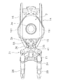
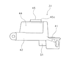
図9は、アッパブラケット31の平面図である。図10は、アッパブラケット31の側面図である。図11は、アッパブラケット31の背面図である。図9から図11に示すように、アッパブラケット31は、ステアリングシャフト連結部41と、左連結部42と、右連結部43と、中央ブラケット部44と、を含む。アッパブラケット31は、鋳造で作られており、ステアリングシャフト連結部41と、左連結部42と、右連結部43と、中央ブラケット部44とは、一体に形成されている。
FIG. 9 is a plan view of the
ステアリングシャフト連結部41には、ステアリングシャフト21の上部が連結される。ステアリングシャフト連結部41は、孔410を含む。孔410には、ステアリングシャフト21の上部が挿入される。
An upper portion of the steering
左連結部42は、左筒部材25の上部に連結される。左連結部42は、左孔420を含む。左孔420には、左筒部材25の上部が挿入される。右連結部43は、右筒部材26の上部に連結される。右連結部43は、右孔430を含む。右孔430には、右筒部材26の上部が挿入される。
The
中央ブラケット部44は、車幅方向において左連結部42と右連結部43との間に位置する。中央ブラケット部44は、ステアリングシャフト連結部41の前方に位置する。中央ブラケット部44は、左ホルダ連結部45と右ホルダ連結部46とを含む。左ホルダ連結部45と右ホルダ連結部46とは、左右に互いに離れて配置される。ステアリングシャフト連結部41の前端は、左ホルダ連結部45の後端及び右ホルダ連結部46の後端よりも前方に位置する。ステアリングシャフト連結部41の前端は、左ホルダ連結部45の前端及び右ホルダ連結部46の前端よりも後方に位置する。左ホルダ連結部45は、孔450を含む。右ホルダ連結部46は、孔460を含む。
The
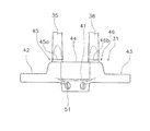
図12は、左右の下ホルダ部35,36が取り付けられたアッパブラケット31の平面図である。図13は、左右の下ホルダ部35,36が取り付けられたアッパブラケット31の側面図である。図14は、左右の下ホルダ部35,36が取り付けられたアッパブラケット31の背面図である。図15は、ホルダ部材32とアッパブラケット31との側面断面図である。
FIG. 12 is a plan view of the
図12から図15に示すように、左ホルダ連結部45は、左下ホルダ部35の下部に連結される。図15に示すように、左ホルダ連結部45の孔450には、締結部材47が挿入される。締結部材47は、左下ホルダ部35の底面から突出している。締結部材47には、ナット49が螺合する。これにより、左ホルダ連結部45は、締結部材47によって左下ホルダ部35に固定される。
As shown in FIGS. 12 to 15, the left
同様に、右ホルダ連結部46の孔460には、図5に示す締結部材48が挿入される。締結部材48は、右下ホルダ部36の底面から突出している。締結部材48には、図5に示すナット50が螺合する。これにより、右ホルダ連結部46は、締結部材48によって右下ホルダ部36に固定される。
Similarly, the
図13に示すように、左下ホルダ部35の側面には凹凸形状350が設けられている。左下ホルダ部35の上面351は、凹部352を含む。凹部352は下方に向けて凹んでおり、円弧状の形状を有する。この凹部352に、ステアリングバー23の被保持部231の一部が配置される。左下ホルダ部35の前面353及び背面354は、下方に向かって先細りの形状を有する。左下ホルダ部35の底面355は平坦な形状を有しており、左ホルダ連結部45に取り付けられる。
As shown in FIG. 13, an
図12に示すように、左下ホルダ部35の上面351には、上述した固定部材40が螺合するネジ孔356,357が設けられている。同様に、右下ホルダ部36の上面361には、上述した固定部材40が螺合するネジ孔366,367が設けられている。
As shown in FIG. 12, screw holes 356 and 357 into which the above-described fixing
図15に示すように、ステアリングシャフト連結部41は、左ホルダ連結部45及び締結部材47よりも下方に位置する。左ホルダ連結部45の後端45aから被保持部231までの上下方向寸法(以下、「ホルダ部材32によるステアリングバー23の保持高さ」と呼ぶ)L2は、締結部材47からステアリングシャフト連結部41までの上下方向寸法L0より大きい。
As shown in FIG. 15, the steering
図15に示すように、ステアリングシャフト連結部41は、下方に突出する突出部51を含む。突出部51の下方には、ステアリングシャフト21とに取り付けられたナット52が配置されている。突出部51は、ナット52に接触している。ステアリングシャフト連結部41は、ナット52とナットキャップ53とによって挟まれて、ステアリングシャフト21に固定される。ナット52の下方にはベアリング54が配置されており、ステアリングシャフト21は、ベアリング54を介してヘッドパイプ11に支持されている。
As shown in FIG. 15, the steering
図13に示すように、ステアリングシャフト21の軸線方向における左下ホルダ部35の寸法B1は、ステアリングシャフト21の軸線方向における中央ブラケット部44の寸法B2よりも大きい。左ホルダ連結部45は、左連結部42よりも上方に位置する。従って、左ホルダ部材32の下端部は、左連結部42よりも上方に位置する。
As shown in FIG. 13, the dimension B1 of the lower
ステアリングシャフト21の軸線方向における左ホルダ連結部45と左連結部42との間の距離B3は、ステアリングシャフト21の軸線方向における左連結部42の寸法B4より大きい。ステアリングシャフト連結部41の底部は、左連結部42の底部、及び、右連結部43の底部よりも下方に位置する。すなわち突出部51の底部は、左連結部42の底部、及び、右連結部43の底部よりも下方に位置する。
A distance B3 between the left
図4に示すように、ステアリングバー23の左外端232は、燃料タンク3よりも上方に位置する。被保持部231から左外端232までの上下方向寸法(以下、「ステアリングバー23の高さ」と呼ぶ)L3は、被保持部231からステアリングシャフト連結部41までの上下方向寸法(以下、「連結部材22によるステアリングバー23の保持高さ」と呼ぶ)L1よりも小さい。なお、ここでいう被保持部231の位置は、被保持部231の下端の位置を意味する。すなわち、被保持部231の位置は、上述した左下ホルダ部35の凹部352の下端の位置を意味するものとする。
As shown in FIG. 4, the left
図7に示すように、燃料タンク3の上端3aは、アッパブラケット31よりも上方に位置する。左下ホルダ部35の上端は、燃料タンク3の上端3aよりも上方に位置する。燃料タンク3の上端3aは、左下ホルダ部35の凹部352の下端よりも上方に位置する。従って、燃料タンク3の上端3aは、被保持部231の下端よりも上方に位置する。
As shown in FIG. 7, the
図7に示すように、車両前後方向において、燃料タンク3とアッパブラケット31との間には、メインスイッチ55が配置される。メインスイッチ55は、エンジン5の始動時に操作される。メインスイッチ55の上端は、左下ホルダ部35の上端よりも下方に位置する。メインスイッチ55の上端は、中央ブラケット部44の上端よりも下方に位置する。メインスイッチ55の上端は、ステアリングシャフト連結部41の上端よりも上方に位置する。メインスイッチ55の下端は、ステアリングシャフト連結部41の下端よりも下方に位置する。メインスイッチ55の下端は、ヘッドパイプ11の上端部(上端面)11aよりも下方に位置する。メインスイッチ55の中心軸線Qは、前方から後方に向けて下方から上方に向かうように斜めに延びている。メインスイッチ55は、フレーム2に固定されたシリンダ55aとキー55bを含む。
As shown in FIG. 7, a
右下ホルダ部36と右ホルダ連結部46と右連結部43とは、それぞれ左下ホルダ部35と左ホルダ連結部45と左連結部42と、左右対称に設けられている。従って、右下ホルダ部36と右ホルダ連結部46と右連結部43との形状、及び、他の部材に対する位置関係は、左下ホルダ部35と左ホルダ連結部45と左連結部42との形状、及び、他の部材に対する位置関係と同様である。
The lower
図16は、仮想比較例を示すステアリング装置、フレーム、及び燃料タンクの拡大側面図である。図16に示すように、アッパブラケットA42を締結部材(図7参照)と同程度の高さになるように、ヘッドパイプA11の上端部A11aを設定した場合、上端部A11aが距離Dだけ後方へ位置する。そうすると、このヘッドパイプA11やアッパブラケットA42に対してメインキーA55のクリアランスを設定しなければならない。このため、メインキーA55をメインキー55よりも後方に配置する必要が生じる。その結果、燃料タンクA3の前端A3bも燃料タンク3の前端3bよりも後方に位置させなければならない。この場合、タンクA3の容量は、タンク3の容量よりも少なくなる。特に、メインスイッチA55の中心軸線Qを前方から後方に向けて下方から上方に向かうように設定すると、斜めに延びるキーA55bの操作空間Sと燃料タンクA3とのクリアランスも大きく確保しなければならないので、タンクA3の容量はより少なくなり易い。
FIG. 16 is an enlarged side view of a steering device, a frame, and a fuel tank showing a virtual comparison example. As shown in FIG. 16, when the upper end A11a of the head pipe A11 is set so that the upper bracket A42 has the same height as the fastening member (see FIG. 7), the upper end A11a moves backward by a distance D. To position. Then, the clearance of the main key A55 must be set for the head pipe A11 and the upper bracket A42. For this reason, it is necessary to dispose the main key A55 behind the
以上説明した本実施形態に係る鞍乗型車両1は、以下の特徴を有する。
The straddle-
一般的に鞍乗型車両は小型であり、構成部品の配置スペースが限られる。そのため、タンク容量を大きく確保するために、燃料タンクを大型化することには様々な制限がある。例えば、燃料タンク3を上方に拡張することは、デザイン或いは乗車ポジションを保持する観点から制限される。燃料タンク3の後方への拡張は、シート4の位置が後方に位置することになるため、乗車ポジションを保持する観点から制限される。燃料タンク3の車幅方向への拡張は、ニーグリップに影響を与え、車両の乗り心地に影響を与えることから制限される。燃料タンク3の下方への拡張は、燃料タンク3とエンジン5との間の距離を保つ観点から制限される。また、燃料タンク3の前方への拡張は、ステアリングバー23と燃料タンク3等との干渉の観点から制限される。
In general, saddle riding type vehicles are small in size, and space for arranging components is limited. Therefore, there are various restrictions on increasing the size of the fuel tank in order to ensure a large tank capacity. For example, expanding the
これに対して、本実施形態に係る鞍乗型車両1では、左右の下ホルダ部35,36とアッパブラケット31とによって、ステアリングバー23の被保持部231の位置を高く維持すると共に、ヘッドパイプ11の上端部11aの位置を低くすることができる。ヘッドパイプ11は斜め下前方に延びているため、ヘッドパイプ11の上端部11aの位置が低くなることにより、ヘッドパイプ11の上端部11aの位置が高い場合と比べて、ヘッドパイプ11の上端部11aを前方に配置することができる。それにより、燃料タンク3とヘッドパイプ11との間のスペースを前方に大きく確保することができる。これにより、燃料タンク3の前端3bをより前方に配置することができ、タンク容量を大きく確保することができる。また、ステアリングバー23の被保持部231の位置を高くすることができるので、ステアリングバー23が燃料タンク3等と干渉し難くなる。
On the other hand, in the saddle riding
ステアリングシャフト連結部41は、左右のホルダ連結部45,46及び左右の締結部材47,48よりも下方に位置している。すなわち、左右のホルダ連結部45,46に対してステアリングシャフト連結部41の位置が相対的に低くなっており、左右のホルダ連結部45,46の後端45a,46aとステアリングシャフト連結部41との間の距離が上下方向に長くなっている。これにより、左右の下ホルダ部35,36のみを上下に長くする場合と比べて、左右の下ホルダ部35,36が過度に長くなることが抑制される。このため、左右の下ホルダ部35,36の強度を確保し易くすることができ、ホルダ部材32を小型化することが可能になる。
The steering
また、ステアリングバー23の高さL3が、連結部材22によるステアリングバー23の保持高さL1よりも小さい。そのため、ホルダ部材32によるステアリングバー23の保持高さL2が大きくなっても、ステアリングバー23の外端232,233の位置が高くなり過ぎることを抑制することができる。或いは、ホルダ部材32によるステアリングバー23の保持高さL2によってステアリングバー23の外端232,233の位置を高く維持しながら、ステアリングバー23の高さL3を小さく抑えることができる。これにより、ステアリングバー23の外端232,233の位置を高く維持するためにステアリングバー23の高さL3を過度に大きくする場合と比べて、操作性の低下を抑えることができる。
Further, the height L3 of the
さらに、ステアリングバー23の高さL3が、連結部材22によるステアリングバー23の保持高さL1よりも小さい。保持高さL1とステアリングバー23の高さL3との合計(ステアリングシャフト連結部41からステアリングバー23の外端232,233までの高さ)を同じにした場合で、ステアリングバー23の高さL3を、連結部材22によるステアリングバー23の保持高さL1以上にした場合に比べて、アッパブラケット31とステアリングバー23の延在部234,235との間に大きな空間が確保される。そのため、ステアリングバー23を回動させた際に、延在部234,235が燃料タンク3等に干渉し難くなる。その結果、車両の大型化を抑えながら、ステアリングバー23との干渉を避けつつ燃料タンク3を前方に拡張して、タンク容量を増大させることができる。
Further, the height L3 of the
以上、本発明の一実施形態について説明したが、本発明は上記実施形態に限定されるものではなく、発明の要旨を逸脱しない範囲で種々の変更が可能である。 As mentioned above, although one Embodiment of this invention was described, this invention is not limited to the said embodiment, A various change is possible in the range which does not deviate from the summary of invention.
鞍乗型車両1は、自動二輪車以外の車両であってもよい。前輪8の数は、1つに限らず2つ以上であってもよい。後輪9の数は、1つに限らず2つ以上であってもよい。
The saddle riding
アッパブラケット31の形状が変更されてもよい。アッパブラケット31は、鋳造以外の製造方法で形成されてもよい。ホルダ部材32の形状が変更されてもよい。燃料タンク3、アッパブラケット31、ホルダ部材32、フレーム2等の位置関係が変更されてもよい。
The shape of the
車両前後方向において、燃料タンク3とアッパブラケット31との間に配置される部材は、メインスイッチ55に限らず、他の部材が配置されてもよい。また、燃料タンク3とアッパブラケット31との間に部材が配置されなくてもよい。この場合においては、当該部材の省略により、燃料タンク3の前端3bをさらに前方に配置することができる。
In the vehicle front-rear direction, the member disposed between the
また、メインキー55をシリンダ55aとキー55bとで構成したが、電子キーを携帯したライダーが乗車した場合にシリンダ55aのロックを解除する構成とし、キー55bの代わりにノブ形状を用いてもよい。
Further, the main key 55 is composed of the
本発明によれば、乗車ポジションを保持し、且つ、乗り心地の低下、車両の大型化、及び燃料タンク等とステアリング装置との干渉を抑えながら、燃料タンクの容量を拡大することができる。 According to the present invention, it is possible to increase the capacity of the fuel tank while maintaining the boarding position and suppressing a decrease in riding comfort, an increase in the size of the vehicle, and interference between the fuel tank and the steering device.
2 フレーム
4 シート
6 ステアリング装置
3 燃料タンク
11 ヘッドパイプ
14 メインフレーム
21 ステアリングシャフト
22 連結部材
23 ステアリングバー
31 アッパブラケット
32 ホルダ部材
47 締結部材
231 被保持部
232 外端
234 延在部
41 ステアリングシャフト連結部
45 ホルダ連結部
72 レンズ部
7 ヘッドライト
15 左メインフレーム
16 右メインフレーム
8 前輪
25 左筒部材
26 右筒部材
42 左連結部
43 右連結部
44 中央ブラケット部
34 上ホルダ部
35 下ホルダ部
2
Claims (13)
前記フレームに支持されるシートと、
前記シートよりも前方に配置され、前記フレームに回動可能に支持されるステアリング装置と、
前記ステアリング装置の後方、且つ、前記シートの前方に配置される燃料タンクと、
を備え、
前記フレームは、
車幅方向における中心に配置され、斜め下前方へ延びるヘッドパイプと、
前記ヘッドパイプから後方、且つ、下方に延びると共に、前記燃料タンクを支持し、車両側面視において前記燃料タンクの上端よりも下方に位置するメインフレームと、
を含み、
前記ステアリング装置は、
前記ヘッドパイプに挿入されるステアリングシャフトと、
前記ステアリングシャフトの上部に連結される連結部材と、
前記連結部材に保持されるステアリングバーと、
を含み、
前記連結部材は、
前記ステアリングシャフトが連結されるアッパブラケットと、
前記アッパブラケットの上方に配置され、前記アッパブラケットよりも上方に前記ステアリングバーを保持するホルダ部材と、
前記ホルダ部材を前記アッパブラケットに締結する締結部材と、
を含み、
前記ステアリングバーは、
前記ホルダ部材に保持される被保持部と、
車幅方向における外端と、
前記被保持部から前記外端に向けて車幅方向における外方に延びる延在部と、
を含み、
前記アッパブラケットは、
前記ステアリングシャフトの上部が連結されるステアリングシャフト連結部と、
前記締結部材が上下に貫通すると共に、前記ホルダ部材の下部に連結されるホルダ連結部と、
を含み、
前記ステアリングシャフト連結部は、前記ホルダ連結部及び前記締結部材よりも下方に位置し、
前記ホルダ連結部の後端から前記被保持部までの上下方向寸法(L2)は、前記締結部材から前記ステアリングシャフト連結部までの上下方向寸法(L0)より大きく、
前記被保持部から前記外端までの上下方向寸法(L3)は、前記被保持部から前記ステアリングシャフト連結部までの上下方向寸法(L1)よりも小さい、
鞍乗型車両。 Frame,
A seat supported by the frame;
A steering device disposed in front of the seat and rotatably supported by the frame;
A fuel tank disposed behind the steering device and in front of the seat;
With
The frame is
A head pipe disposed at the center in the vehicle width direction and extending obliquely downward and forward;
A main frame that extends rearward and downward from the head pipe, supports the fuel tank, and is located below the upper end of the fuel tank in a vehicle side view;
Including
The steering device is
A steering shaft inserted into the head pipe;
A connecting member connected to an upper portion of the steering shaft;
A steering bar held by the connecting member;
Including
The connecting member is
An upper bracket to which the steering shaft is coupled;
A holder member disposed above the upper bracket and holding the steering bar above the upper bracket;
A fastening member for fastening the holder member to the upper bracket;
Including
The steering bar is
A held portion held by the holder member;
An outer end in the vehicle width direction;
An extending portion extending outward in the vehicle width direction from the held portion toward the outer end;
Including
The upper bracket is
A steering shaft connecting portion to which an upper portion of the steering shaft is connected;
The fastening member penetrates up and down, and a holder coupling portion coupled to the lower portion of the holder member;
Including
The steering shaft connecting portion is positioned below the holder connecting portion and the fastening member,
The vertical dimension (L2) from the rear end of the holder connecting part to the held part is larger than the vertical dimension (L0) from the fastening member to the steering shaft connecting part,
The vertical dimension (L3) from the held part to the outer end is smaller than the vertical dimension (L1) from the held part to the steering shaft connecting part,
Saddle type vehicle.
請求項1に記載の鞍乗型車両。 A front end of the steering shaft connecting portion is positioned forward of a rear end of the holder connecting portion;
The straddle-type vehicle according to claim 1.
前記ヘッドパイプの上端部の下端は、前記レンズ部の上端よりも下方に位置する、
請求項1又は2のいずれかに記載の鞍乗型車両。 A headlight including a lens portion and disposed in front of the head pipe;
The lower end of the upper end portion of the head pipe is located below the upper end of the lens portion,
The straddle-type vehicle according to claim 1 or 2.
請求項1から3のいずれかに記載の鞍乗型車両。 An upper end of the fuel tank is located above the upper bracket;
The straddle-type vehicle according to any one of claims 1 to 3.
請求項1から4のいずれかに記載の鞍乗型車両。 An upper end of the holder member is located above an upper end of the fuel tank;
The straddle-type vehicle according to any one of claims 1 to 4.
車両平面視において、前記燃料タンクは、前記左メインフレームと前記右メインフレームとにそれぞれ重なる、
請求項1から5のいずれかに記載の鞍乗型車両。 The main frame includes a left main frame and a right main frame formed in a pair of left and right,
In the vehicle plan view, the fuel tank overlaps the left main frame and the right main frame, respectively.
The straddle-type vehicle according to any one of claims 1 to 5.
請求項1から6のいずれかに記載の鞍乗型車両。 The maximum width portion of the fuel tank is disposed at the front portion of the fuel tank,
The straddle-type vehicle according to any one of claims 1 to 6.
請求項1から7のいずれかに記載の鞍乗型車両。 The longitudinal dimension of the head pipe is shorter than the vertical dimension of the head pipe.
The straddle-type vehicle according to any one of claims 1 to 7.
前記ステアリング装置は、前記前輪を回転可能に支持する左筒部材及び右筒部材をさらに含み、
前記アッパブラケットは、
前記左筒部材の上部に連結される左連結部と、
前記右筒部材の上部に連結される右連結部と、
をさらに含み、
前記ステアリングシャフト連結部の底部は、前記左連結部の底部、及び、前記右連結部の底部よりも下方に位置する、
請求項1から8のいずれかに記載の鞍乗型車両。 A front wheel,
The steering device further includes a left cylinder member and a right cylinder member that rotatably support the front wheel,
The upper bracket is
A left connecting portion connected to an upper portion of the left cylinder member;
A right connecting portion connected to an upper portion of the right cylinder member;
Further including
The bottom portion of the steering shaft connecting portion is positioned below the bottom portion of the left connecting portion and the bottom portion of the right connecting portion.
The straddle-type vehicle according to any one of claims 1 to 8.
前記ホルダ連結部は、前記中央ブラケット部に設けられており、
前記ホルダ部材は、
前記ステアリングバーの上方に配置される上ホルダ部と、
前記ステアリングバーの下方に配置される下ホルダ部と、
を含み、
前記ステアリングシャフトの軸線方向における下ホルダ部の寸法は、前記ステアリングシャフトの軸線方向における前記中央ブラケット部の寸法よりも大きい、
請求項9に記載の鞍乗型車両。 The upper bracket further includes a central bracket portion located between the left connecting portion and the right connecting portion in the vehicle width direction,
The holder connecting portion is provided in the central bracket portion,
The holder member is
An upper holder part disposed above the steering bar;
A lower holder portion disposed below the steering bar;
Including
The dimension of the lower holder part in the axial direction of the steering shaft is larger than the dimension of the central bracket part in the axial direction of the steering shaft.
The straddle-type vehicle according to claim 9.
請求項9又は10に記載の鞍乗型車両。 A lower end portion of the holder member is positioned above the left connecting portion;
The straddle-type vehicle according to claim 9 or 10.
請求項1から11のいずれかに記載の鞍乗型車両。 A member further disposed between the fuel tank and the upper bracket in the vehicle longitudinal direction;
The straddle-type vehicle according to any one of claims 1 to 11.
前記メインキーは、中心軸線が前方から後方に向けて下方から上方に向かうように斜めに延びている請求項1から12のいずれかに記載の鞍乗型車両。 The member disposed between the fuel tank and the upper bracket is a main key,
The straddle-type vehicle according to any one of claims 1 to 12, wherein the main key extends obliquely so that a center axis thereof is directed from the front to the rear and directed from the lower side to the upper side.
Priority Applications (2)
| Application Number | Priority Date | Filing Date | Title |
|---|---|---|---|
| JP2015138344A JP2017019385A (en) | 2015-07-10 | 2015-07-10 | Saddle-riding type vehicle |
| EP16169649.7A EP3115288B1 (en) | 2015-07-10 | 2016-05-13 | Straddled vehicle |
Applications Claiming Priority (1)
| Application Number | Priority Date | Filing Date | Title |
|---|---|---|---|
| JP2015138344A JP2017019385A (en) | 2015-07-10 | 2015-07-10 | Saddle-riding type vehicle |
Publications (1)
| Publication Number | Publication Date |
|---|---|
| JP2017019385A true JP2017019385A (en) | 2017-01-26 |
Family
ID=55969038
Family Applications (1)
| Application Number | Title | Priority Date | Filing Date |
|---|---|---|---|
| JP2015138344A Pending JP2017019385A (en) | 2015-07-10 | 2015-07-10 | Saddle-riding type vehicle |
Country Status (2)
| Country | Link |
|---|---|
| EP (1) | EP3115288B1 (en) |
| JP (1) | JP2017019385A (en) |
Families Citing this family (1)
| Publication number | Priority date | Publication date | Assignee | Title |
|---|---|---|---|---|
| JP2018131145A (en) * | 2017-02-17 | 2018-08-23 | ヤマハ発動機株式会社 | Straddled vehicle |
Family Cites Families (9)
| Publication number | Priority date | Publication date | Assignee | Title |
|---|---|---|---|---|
| JPS60113788A (en) * | 1983-11-26 | 1985-06-20 | ヤマハ発動機株式会社 | Fixture for bar handle in saddling type car |
| JPH0891273A (en) * | 1994-09-27 | 1996-04-09 | Suzuki Motor Corp | Handle bar holding structure of motorcycle |
| JPH0899677A (en) * | 1994-09-29 | 1996-04-16 | Suzuki Motor Corp | Steering stem assembling structure in front fork |
| JP2000072077A (en) * | 1998-09-02 | 2000-03-07 | Honda Motor Co Ltd | Handle support structure for two-wheeler |
| US6237710B1 (en) * | 1998-10-26 | 2001-05-29 | Yamaha Hatsudoki Kabushiki Kaisha | Locking arrangement for motorcycle |
| US7699331B2 (en) * | 2007-05-18 | 2010-04-20 | Mcvickar Matthew | Motorcycle-stance alteration kit |
| US8317214B2 (en) * | 2010-03-30 | 2012-11-27 | George John Athanasiou | Shock and vibration damping handlebar mounting assembly |
| JP2012144145A (en) * | 2011-01-12 | 2012-08-02 | Honda Motor Co Ltd | Structure for supporting handle of saddle-type vehicle |
| JP6130115B2 (en) | 2012-09-20 | 2017-05-17 | 川崎重工業株式会社 | Saddle type vehicle handle lock mechanism mounting structure and mounting method thereof |
-
2015
- 2015-07-10 JP JP2015138344A patent/JP2017019385A/en active Pending
-
2016
- 2016-05-13 EP EP16169649.7A patent/EP3115288B1/en active Active
Also Published As
| Publication number | Publication date |
|---|---|
| EP3115288B1 (en) | 2019-08-21 |
| EP3115288A1 (en) | 2017-01-11 |
Similar Documents
| Publication | Publication Date | Title |
|---|---|---|
| JP5797367B1 (en) | vehicle | |
| JP3157145U (en) | Motorcycle | |
| JP2015033900A (en) | Fitting structure of front cowl stay in saddle-riding type vehicle | |
| JP5607016B2 (en) | Guard pipe mounting structure for motorcycles | |
| JP2014184827A (en) | Saddle-riding type vehicle | |
| US10351191B2 (en) | Stand support structure of saddle riding vehicle | |
| JP2015085749A (en) | Saddle-riding type vehicle | |
| US20150307148A1 (en) | Side mirror for straddle vehicle | |
| JP2012144145A (en) | Structure for supporting handle of saddle-type vehicle | |
| JP2017019385A (en) | Saddle-riding type vehicle | |
| JP6448157B2 (en) | Motorcycle headlight guard structure | |
| CN101612972A (en) | Motor bike | |
| TWI764595B (en) | Straddled vehicle | |
| JP2017121849A (en) | Saddle-riding type vehicle | |
| EP3002187B1 (en) | Vehicle | |
| JP2020037341A (en) | Saddle-riding type vehicle | |
| EP2781441B1 (en) | Saddle type vehicle | |
| WO2017134832A1 (en) | Saddle-type vehicle | |
| JP2010155578A (en) | Cover device of motorcycle | |
| JP4732409B2 (en) | Oil level confirmation structure for motorcycles | |
| JP2017121924A (en) | Saddle riding-type vehicle | |
| JP2020059437A (en) | Saddle-riding type vehicle | |
| JP2006205985A (en) | Frame for motorcycle | |
| JP6395343B2 (en) | Vehicle direction indicator | |
| JP2017094800A (en) | Saddle-riding type vehicle |