JP2012144145A - Structure for supporting handle of saddle-type vehicle - Google Patents
Structure for supporting handle of saddle-type vehicle Download PDFInfo
- Publication number
- JP2012144145A JP2012144145A JP2011004000A JP2011004000A JP2012144145A JP 2012144145 A JP2012144145 A JP 2012144145A JP 2011004000 A JP2011004000 A JP 2011004000A JP 2011004000 A JP2011004000 A JP 2011004000A JP 2012144145 A JP2012144145 A JP 2012144145A
- Authority
- JP
- Japan
- Prior art keywords
- top bridge
- handle
- holder
- support structure
- mount rubber
- Prior art date
- Legal status (The legal status is an assumption and is not a legal conclusion. Google has not performed a legal analysis and makes no representation as to the accuracy of the status listed.)
- Pending
Links
Images


Landscapes
- Steering Devices For Bicycles And Motorcycles (AREA)
Abstract
【課題】ハンドルの振動低減効果を長期間にわたり維持する。
【解決手段】ハンドルパイプ36を支持するアンダーホルダー45とトップブリッジ32との間に、弾性部材である上側マウントラバー56を配置し、アンダーホルダー45を、上側マウントラバー56を介してトップブリッジ32に浮動支持し、トップブリッジ32の上方に、上側マウントラバー56の外周側を囲ってマウントラバー56の変形を規制する規制部材であるハンドルホルダーワッシャー55を配置する。
【選択図】図3An object of the present invention is to maintain a vibration reduction effect of a handle for a long period of time.
An upper mount rubber which is an elastic member is disposed between an under holder supporting a handle pipe and a top bridge, and the under holder is attached to the top bridge via the upper mount rubber. A handle holder washer 55 is disposed above the top bridge 32 so as to restrict the deformation of the mount rubber 56 so as to surround the outer periphery of the upper mount rubber 56.
[Selection] Figure 3
Description
本発明は、鞍乗型車両のハンドル支持構造に関する。 The present invention relates to a handle support structure for a saddle-ride type vehicle.
この種の技術として、トップブリッジに形成された孔に環ブッシュからなる弾性部材を挿入し、ハンドルホルダーに凸部を設け、この凸部を上記孔及び弾性部材に挿入して支持し、ハンドルホルダーによってハンドルパイプを支持する構造が従来から知られている(特許文献1参照)。このような構造では、弾性部材の変形が少なく、また、弾性部材が外観に現れないため、外観性を良好にすることができる。 As this type of technology, an elastic member made of a ring bush is inserted into a hole formed in the top bridge, a convex portion is provided on the handle holder, and this convex portion is inserted into and supported by the hole and the elastic member. Conventionally, a structure for supporting a handle pipe is known (see Patent Document 1). In such a structure, deformation of the elastic member is small, and since the elastic member does not appear in the appearance, the appearance can be improved.
ところで、鞍乗型車両では、トップブリッジを薄い板材で構成して、トップブリッジに孔を形成し、この孔にハンドルホルダーを支持するものがあるが、このような構造は、トップブリッジが薄い板材であるため、特許文献1に開示されるような構造に適さない。そのため、トップブリッジを薄い板材で構成するような場合には、トップブリッジとハンドルホルダーとの間に弾性部材を設けて、ハンドルパイプの振動を抑制する場合がある。 By the way, in a saddle-ride type vehicle, there is a structure in which a top bridge is formed of a thin plate material, a hole is formed in the top bridge, and a handle holder is supported in the hole. Therefore, it is not suitable for the structure disclosed in Patent Document 1. Therefore, when the top bridge is made of a thin plate material, an elastic member may be provided between the top bridge and the handle holder to suppress vibration of the handle pipe.
しかしながら、弾性部材をトップブリッジとハンドルホルダーとの間に設ける場合には、使用に伴って弾性部材に変形が生じ易く、ハンドルの振動低減効果を長期間にわたり維持するのが困難な場合があった。 However, when the elastic member is provided between the top bridge and the handle holder, the elastic member is likely to be deformed with use, and it may be difficult to maintain the vibration reduction effect of the handle over a long period of time. .
本発明は係る実情に鑑みてなされたものであり、ハンドルの振動低減効果を長期間にわたり維持できる鞍乗型車両のハンドル支持構造の提供を目的とする。 The present invention has been made in view of such circumstances, and an object of the present invention is to provide a handle support structure for a straddle-type vehicle that can maintain the vibration reduction effect of the handle over a long period of time.
上記課題を解決するために、請求項1に記載の発明は、ヘッドパイプ(8)に回動可能に支持されるステアリングシャフト(34)と、前輪(4)を軸支する左右一対のフロントフォーク(31)と、前記フロントフォーク(31)と前記ステアリングシャフト(34)とを連結するトップブリッジ(32)とを備え、操舵を入力するハンドルパイプ(36)を、前記ステアリングシャフト(34)の上方に配置して前記トップブリッジ(32)に固定する鞍乗型車両(1)において、前記ハンドルパイプ(36)が、上方に配置されるアッパーホルダー(46)と、下方に配置されるアンダーホルダー(45)とで挟まれ、前記トップブリッジ(32)に、トップブリッジ孔部(43)が形成され、前記アンダーホルダー(45)は、下方に突出する凸部(52)を備え、該凸部(52)は、前記トップブリッジ孔部(43)に挿し込まれ、前記アンダーホルダー(45)と前記トップブリッジ(32)との間に、弾性部材であるマウントラバー(56,70,80)が配置され、前記アンダーホルダー(45)は、前記マウントラバー(56,70,80)を介して前記トップブリッジ(32)に浮動支持され、前記トップブリッジ(32)の上方に、前記マウントラバー(56,70,80)の外周側を囲って該マウントラバー(56,70,80)の変形を規制する規制部材(55,71,81)が配置されていることを特徴とする鞍乗型車両のハンドル支持構造を提供する。 In order to solve the above-mentioned problems, the invention according to claim 1 is directed to a steering shaft (34) rotatably supported by a head pipe (8) and a pair of left and right front forks that pivotally support a front wheel (4). (31) and a top bridge (32) connecting the front fork (31) and the steering shaft (34), and a handle pipe (36) for inputting steering is provided above the steering shaft (34). In the saddle-ride type vehicle (1) which is disposed on the top bridge (32) and fixed to the top bridge (32), the handle pipe (36) includes an upper holder (46) disposed above and an under holder ( 45), a top bridge hole (43) is formed in the top bridge (32), and the under holder (45) A protruding protrusion (52) is provided, and the protrusion (52) is inserted into the top bridge hole (43), and is elastic between the under holder (45) and the top bridge (32). Mount rubber (56, 70, 80), which is a member, is disposed, and the under holder (45) is floated and supported by the top bridge (32) via the mount rubber (56, 70, 80), and the top A restricting member (55, 71, 81) that surrounds the outer peripheral side of the mount rubber (56, 70, 80) and restricts deformation of the mount rubber (56, 70, 80) is disposed above the bridge (32). A steering wheel support structure for a saddle-ride type vehicle is provided.
請求項2に記載の発明は、請求項1に記載の鞍乗型車両のハンドル支持構造において、前記規制手段(55,71,81)が、ワッシャー(55,71)であり、前記トップブリッジ(32)と前記マウントラバー(56,70)との間に配置され、その外周側が前記マウントラバー(56,70)側に向けて上方に突出していることを特徴とする。 According to a second aspect of the present invention, in the handle support structure for the saddle riding type vehicle according to the first aspect, the restriction means (55, 71, 81) is a washer (55, 71), and the top bridge ( 32) and the mount rubber (56, 70), and its outer peripheral side protrudes upward toward the mount rubber (56, 70).
請求項3に記載の発明は、請求項1又は2に記載の鞍乗型車両のハンドル支持構造において、前記マウントラバー(56)が、前記アンダーホルダー(45)の前記凸部(52)と前記トップブリッジ孔部(43)との間に配置されるカラー部(60)を備えている
ことを特徴とする。
According to a third aspect of the present invention, in the handle support structure for a saddle-ride type vehicle according to the first or second aspect, the mount rubber (56) is connected to the convex portion (52) of the under holder (45). A collar portion (60) disposed between the top bridge hole portion (43) and the top bridge hole portion (43) is provided.
請求項4に記載の発明は、請求項2に記載の鞍乗型車両のハンドル支持構造において、前記ワッシャー(71)の内周側が、前記アンダーホルダー(45)の前記凸部(52)と前記トップブリッジ孔部(43)との間に延びるように下方に突出していることを特徴とする。 According to a fourth aspect of the present invention, in the handle support structure for the saddle riding type vehicle according to the second aspect, the inner peripheral side of the washer (71) is connected to the convex portion (52) of the under holder (45) and the It protrudes below so that it may extend between top bridge holes (43).
請求項5に記載の発明は、請求項1に記載の鞍乗型車両のハンドル支持構造において、前記規制部材(81)が、前記トップブリッジ(32)から上方に突出し、前記トップブリッジ(32)と溶接で一体化されていることを特徴とする。 According to a fifth aspect of the present invention, in the handle support structure for the saddle riding type vehicle according to the first aspect, the restriction member (81) protrudes upward from the top bridge (32), and the top bridge (32). And integrated by welding.
請求項6に記載の発明は、請求項1〜5のいずれか1項に記載の鞍乗型車両のハンドル支持構造において、前記規制部材(55,71,81)が、前記アンダーホルダー(45)の外周投影面(D)よりも内側に配置されることを特徴とする。 According to a sixth aspect of the present invention, in the handle support structure for the saddle riding type vehicle according to any one of the first to fifth aspects, the restriction member (55, 71, 81) is the under holder (45). It arrange | positions inside the outer periphery projection surface (D) of this invention, It is characterized by the above-mentioned.
請求項1に記載の発明によれば、マウントラバーによってハンドルパイプの振動を抑制でき、規制部材によってマウントラバーの外側への変形を抑えることができるので、マウントラバーによる振動低減効果を長期間にわたり維持することができる。 According to the first aspect of the present invention, the vibration of the handle pipe can be suppressed by the mount rubber, and the deformation to the outside of the mount rubber can be suppressed by the regulating member, so that the vibration reduction effect by the mount rubber is maintained for a long period of time. can do.
請求項2に記載の発明によれば、ワッシャーの外周側を突出させたので、変形したマウントラバーが外観に現れるのを避けることができる。 According to the second aspect of the invention, since the outer peripheral side of the washer is protruded, it is possible to avoid the appearance of the deformed mount rubber in the appearance.
請求項3に記載の発明によれば、カラー部によって、ハンドルホルダーの動きを抑えることができ、振動低減に加え、操縦性の向上が図れる。 According to the third aspect of the invention, the movement of the handle holder can be suppressed by the collar portion, and in addition to the reduction of vibration, the maneuverability can be improved.
請求項4に記載の発明によれば、ワッシャーの内周側を、アンダーホルダーの凸部とトップブリッジ孔部との間に延びるように下方に突出させることで、ワッシャーの移動を規制することでき、ハンドルホルダーの動きを抑え、振動低減に加え、操縦性の向上が図れる。 According to the fourth aspect of the present invention, the washer movement can be restricted by projecting the inner peripheral side of the washer downward so as to extend between the convex portion of the under holder and the top bridge hole. In addition to suppressing the movement of the handle holder, vibrations can be reduced and maneuverability can be improved.
請求項5に記載の発明によれば、規制部材をトップブリッジと一体とすることで、規制部材によってマウントラバーの変形の抑制とともにハンドルホルダーの動きを抑えることができ、振動低減に加えて、操縦性の向上が図れる。 According to the fifth aspect of the present invention, since the regulating member is integrated with the top bridge, the regulating member can restrain the deformation of the mount rubber and the movement of the handle holder. Can improve the performance.
請求項6に記載の発明によれば、規制部材が外観に現れないようにして外観性を向上できる。 According to the sixth aspect of the invention, the appearance can be improved so that the regulating member does not appear on the appearance.
以下、本発明の各実施形態を図面に基づいて説明する。なお、以下で用いる図面において、矢印FRは車両の前方を示し、矢印UPは車両の上方を示している。 Hereinafter, each embodiment of the present invention will be described with reference to the drawings. In the drawings used below, the arrow FR indicates the front of the vehicle, and the arrow UP indicates the upper side of the vehicle.
<第1の実施形態>
図1に本発明の第1の実施形態に係る構造が適用された自動二輪車1が示されている。自動二輪車1は、車両の基本骨格を形成する車体フレーム2と、車体フレーム2に懸架されたエンジン3と、車体フレーム2の前端部に操舵可能に設けられ前輪4を回動可能に支持する前輪懸架装置5と、車体フレーム2から後方に延ばされ後部に後輪6を回動可能に支持する後輪懸架装置7とを備えている。
<First Embodiment>
FIG. 1 shows a motorcycle 1 to which a structure according to a first embodiment of the present invention is applied. The motorcycle 1 includes a
車体フレーム2には、前輪懸架装置5を操舵可能に支持するヘッドパイプ8と、ヘッドパイプ8の上部から後方に延びた後に湾曲して後斜め下方に延びる左右一対のメインフレーム9,9と、ヘッドパイプ8の下部から後下方に延びるダウンフレーム10と、メインフレーム9,9の湾曲した部位直後から後方に延びる左右一対のシートフレーム11,11と、メインフレーム9,9の下部から後斜め上方に延びシートフレーム11,11と結合する左右一対のサポートフレーム12,12とが含まれている。上記各フレームはアルミニウム合金等のパイプ材から形成されている。
The
ダウンフレーム10の下部にはエンジンハンガ13が取付けられ、エンジン3の前部はエンジンハンガ13によって支持されている。メインフレーム9,9は、エンジン3の後方に回り込むように延びており、エンジン3の後部は、メインフレーム9,9の下部によって支持されている。メインフレーム9,9は、燃料タンク14を上方に配置して支持し、燃料タンク14の後方には、乗員が着座するシート15が配置され、シートフレーム11,11により支持されている。
An
エンジン3は、エンジンハンガ13及びメインフレーム9,9によって支持されたクランクケース16と、クランクケース16から前斜め上方に延在するように結合されたシリンダ部17とを備えている、シリンダ部17には、クランクケース16に結合するシリンダ18と、シリンダ18の上部に結合されたシリンダヘッド19と、シリンダヘッド19の上部を覆うヘッドカバー20とが含まれている。シリンダヘッド19の後面には吸気管21が接続され、シリンダヘッド19の前面には排気管23が接続されている。
The engine 3 includes a
シート15の下方には、左右一対の車体サイドカバー24,24が配置され、車体サイドカバー24,24は、シート15に沿って後輪6の上方まで延びている。車体サイドカバー24,24の後部には、コンビネーションランプ25及びリヤフェンダ26が設けられている。また、前輪4の上方には、フロントフェンダ27が支持されている。
A pair of left and right vehicle body side covers 24, 24 are disposed below the
後輪懸架装置7は、後輪6と、後輪6を後部で支持するスイングアーム28とを備えており、スイングアーム28は、メインフレーム9,9の下部に溶接された左右一対のピボットプレート29,29に支持されている。詳しくは、スイングアーム28は、ピボットプレート29,29間に掛け渡されるように支持され車幅方向に延びるピボット軸30によって、その前部を回動可能に支持され、上下方向に揺動可能にされている。
The rear wheel suspension device 7 includes a rear wheel 6 and a
前輪懸架装置5は、前輪4と、前輪4をその下部で支持する左右一対のフロントフォーク31,31と、フロントフォーク31,31の上端部に架設され、フロントフォーク31,31を連結するトップブリッジ32と、トップブリッジ32の下方においてフロントフォーク31,31に架設されるボトムブリッジ33と、トップブリッジ32及びボトムブリッジ33間をフロントフォーク31,31に沿って延びて双方に連結されるとともに、ヘッドパイプ8に回動可能に支持されるステアリングシャフト34と、トップブリッジ32の上方に固定されるハンドルホルダー35と、ハンドルホルダー35によって支持される操向ハンドルであるハンドルパイプ36とを備えている。フロントフォーク31,31の上部前方にはフロントカウル37が取付けられている。フロントカウル37には、ヘッドライト38等が支持されている。
The front wheel suspension device 5 includes a front wheel 4, a pair of left and
図2は、ハンドルパイプ36を支持するためのトップブリッジ32、ハンドルホルダー35等の各種部材の分解斜視図を示している。トップブリッジ32は、比較的薄い板材からなり、底辺を車両前方に配置して車両後方に先細りとなる略二等辺三角形形状に形成されている。図中には説明の便宜のため車幅方向の中心線CL1を示している。
FIG. 2 is an exploded perspective view of various members such as the
トップブリッジ32の前側両側部には、中心線CL1を挟んで左右に振り分けられたフロントフォーク挿通孔部42,42が形成され、このフロントフォーク挿通孔部42,42部は、フロントフォーク31,31の上端部を挿通して固定する。フロントフォーク挿通孔部42,42よりも後方においてトップブリッジ32の車両前後方向略中央領域の両側部には、中心線CL1を挟んで左右に振り分けられたハンドルホルダー挿通孔部43,43が形成され、このハンドルホルダー挿通孔部43,43は、ハンドルホルダー35を支持する部位である。また、トップブリッジ32の後部において中心線CL1上には、ステアリングシャフト挿通孔部44が形成されている。このステアリングシャフト挿通孔部44は、ステアリングシャフト34の上端部を挿通して固定する。
Front fork insertion holes 42 and 42 are formed on both front sides of the
ハンドルホルダー35は、ハンドルホルダー挿通孔部43,43に支持される左右一対のアンダーホルダー45,45と、アンダーホルダー45,45の上方に配置されるアッパーホルダー46とで構成されている。ハンドルホルダー35では、アンダーホルダー45,45の上方にアッパーホルダー46を配置して、ハンドルパイプ36を挟んで支持する。アッパーホルダー46は、左右のアンダーホルダー45,45に跨ぐようにしてアンダーホルダー45,45に取付けられる。
The
図3は、トップブリッジ32、ハンドルホルダー35等の各種部材の縦断面図を示している。図3も参照し、アンダーホルダー45,45にはそれぞれ、円弧状に凹む一対の下側当接面47,47が形成され、アッパーホルダー46の両側部には、円弧状に凹み、下側当接面47,47と円形空間を形成する一対の上側当接面48,48が形成されている。ハンドルパイプ36は、中心線CL1からそれぞれ左右に対称にクランク形状に形成され、その車幅方向略中央領域を、アンダーホルダー45,45の下側当接面47,47と、アッパーホルダー46の上側当接面48,48とによって挟まれる。
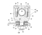
FIG. 3 shows longitudinal sectional views of various members such as the
図2に示すように、1つのアンダーホルダー45には、下側当接面47を挟んで両側に形成されるとともに、トップブリッジ32側に向けて延びて内周面にネジ切加工が施された一対の締結孔49,49が形成され、アッパーホルダー46の四隅には、トップブリッジ32側に貫通するボルト挿通孔50・・・が4つ形成されている。アッパーホルダー46の4つのボルト挿通孔50・・・にそれぞれボルト51・・・が通され、ボルト51・・・がアンダーホルダー45,45の締結孔49・・・に締結されることで、ハンドルパイプ36が固定保持される。
As shown in FIG. 2, one under
アンダーホルダー45,45はそれぞれ、下方に突出する凸部52,52を備え、凸部52,52の下部には、ネジ切加工が施されたネジ部52A,52Aが形成されている。なお、凸部52,52におけるネジ部52A,52A以外の部位を基部52B,52Bと称する。凸部52,52は、トップブリッジ32のハンドルホルダー挿通孔部43,43に挿し込まれ、そのネジ部52A,52Aをトップブリッジ32の下方に配置されるナット54,54に締結される。これにより、アンダーホルダー45,45がトップブリッジ32に固定支持されるようになっている。
Each of the
ハンドルホルダー挿通孔部43,43の上方には、トップブリッジ32側から順に、ハンドルホルダーワッシャー55,55、上側マウントラバー56,56、上側ワッシャー57,57が配置され、ハンドルホルダー挿通孔部43,43の下方には、トップブリッジ32側から順に、下側マウントラバー58,58、下側ワッシャー59,59が配置さ、下側ワッシャー59,59の下方にナット54,54が配置される。
Above the handle holder insertion holes 43, 43, handle
ハンドルホルダーワッシャー55,55、上側マウントラバー56,56、及び上側ワッシャー57,57は、凸部52,52の基部52B,52Bを貫通させるように環状に形成され、アンダーホルダー45の凸部52のネジ部52Aは、上記の各部材を貫通してナット54に締結される。ハンドルホルダーワッシャー55,55、上側マウントラバー56,56、及び上側ワッシャー57,57がトップブリッジ32の上方に配置されることで、アンダーホルダー45,45がトップブリッジ32に対して浮動支持されている。すなわち、アンダーホルダー45,45は、トップブリッジ32に対して上方に離間した状態で支持されている。図3に示すように、アンダーホルダー45,45は下方に向うに従いその幅寸法を漸減させる形状に形成され、その底部45A,45Aは平坦な面に形成されている。
The
凸部52,52の基部52B,52Bは、ハンドルホルダー挿通孔部43,43よりも小径に形成され、基部52B,52Bとハンドルホルダー挿通孔部43,43との間には隙間が形成される。上側マウントラバー56,56は、樹脂材料からなる弾性部材であり、内周面を基部52B,52Bを略当接させている。上側マウントラバー56,56には、その内周側から下方に突出して、基部52B,52Bとハンドルホルダー挿通孔部43,43との間の隙間を埋めるように配置されるカラー部60,60を一体に備えている。
The
ハンドルホルダーワッシャー55,55は、トップブリッジ32と上側マウントラバー56,56との間に挟まれるように配置され、内周面をカラー部60,60の外周面に略当接させている。ハンドルホルダーワッシャー55,55の外周側(外周縁)には、上側マウントラバー56,56側に向けて上方に突出する囲い部61,61が形成されている。囲い部61,61は、上側マウントラバー56,56の外周側に位置し、上側マウントラバー56,56の横方向に変形されて伸びた場合にその変形を抑える。
The
図3において、アンダーホルダー45,45の底部45A,45Aの外側縁部をトップブリッジ32側に投影させた外周投影面Dの縁部を示している。なお、アンダーホルダー45,45の外周において底部45A,45Aの外側縁部は最も内側に位置する。ハンドルホルダーワッシャー55,55の囲い部61,61は、外周投影面Dの略縁部上に位置しており、ハンドルホルダーワッシャー55,55は、外周投影面Dよりも内側に配置される。なお、上側マウントラバー56,56も外周投影面Dよりも内側に配置される。
3, the edge part of the outer periphery projection surface D which projected the outer edge part of
また、トップブリッジ32の下方の下側マウントラバー58,58は、トップブリッジ32と下側ワッシャー59,59との間に挟まれるように配置され、内周面を基部52B,52Bの外周面に略当接させている。この下側マウントラバー58,58は、上側マウントラバー56,56と共に、アンダーホルダー45,45から伝わる上下方向の振動を低減させる。
Further, the
以上に記載したように上記実施形態では、ヘッドパイプ8に回動可能に支持されるステアリングシャフト34と、前輪4を軸支する左右一対のフロントフォーク31,31と、フロントフォーク31,31とステアリングシャフト34とを連結するトップブリッジ32とを備え、操舵を入力するハンドルパイプ36を、ステアリングシャフト34の上方に配置してトップブリッジ32に固定する自動二輪車1において、ハンドルパイプ36が、上方に配置されるアッパーホルダー46と、下方に配置されるアンダーホルダー45,45とで挟まれ、トップブリッジ32に、トップブリッジ孔部であるハンドルホルダー挿通孔部43,43が形成され、アンダーホルダー45,45は、下方に突出する凸部52,52を備え、該凸部52,52が、ハンドルホルダー挿通孔部43,43に挿し込まれている。そして、アンダーホルダー45,45とトップブリッジ32との間には、上側マウントラバー56,56が配置され、アンダーホルダー45,45は、上側マウントラバー56,56を介してトップブリッジ32に浮動支持され、トップブリッジ32の上方には、上側マウントラバー56,56の外周側を囲って上側マウントラバー56,56の変形を規制する囲い部61,61を有するハンドルホルダーワッシャー55,55が配置されている。
As described above, in the above embodiment, the steering
このような構成によれば、上側マウントラバー56,56によってハンドルパイプ36の振動を抑制でき、ハンドルホルダーワッシャー55,55によって上側マウントラバー56,56の外側への変形を抑えることができるので、上側マウントラバー56,56による振動低減効果を長期間にわたり維持することができる。また、ハンドルホルダーワッシャー55,55の外周側を突出させて囲い部61,61を形成したので、変形した上側マウントラバー56,56が外観に現れるのを避けることができる。
According to such a configuration, vibration of the
また、本実施形態では、上側マウントラバー56,56が、アンダーホルダー45,45の凸部52,52とハンドルホルダー挿通孔部43,43との間に配置されるカラー部60,60を備えているので、カラー部60,60によって、アンダーホルダー45,45の動きを抑えることができ、振動低減に加え、操縦性の向上が図れる。
In the present embodiment, the upper mount rubbers 56, 56 include
また、本実施形態において、ハンドルホルダーワッシャー55,55は、アンダーホルダー45,45の底部45Aの外周投影面Dよりも内側に配置されている。これによれば、ハンドルホルダーワッシャー55,55が外観に現れないようにして外観性を向上できる。
In the present embodiment, the
<第2の実施形態>
次に、図4を用いて本発明の第2の実施形態について説明する。本実施形態に係るハンドル支持構造は、第1の実施形態と同様に自動二輪車1に適用されているものとする。第1の実施形態と同様の構成要素については同一符号で示し、説明は省略する。
<Second Embodiment>
Next, a second embodiment of the present invention will be described with reference to FIG. The handle support structure according to the present embodiment is applied to the motorcycle 1 as in the first embodiment. Constituent elements similar to those in the first embodiment are denoted by the same reference numerals, and description thereof is omitted.
本実施形態では、アンダーホルダー45とトップブリッジ32との間に配置される上側マウントラバー70が環状であり、第1の実施形態のようなカラー部60を備えておらず、ハンドルホルダーワッシャー71の形状が第1の実施形態と異なっている。
In the present embodiment, the
アンダーホルダー45の凸部52の基部52Bは、ハンドルホルダー挿通孔部43よりも小径に形成されている。これに対し、ハンドルホルダーワッシャー71の内周側は、凸部52の基部52Bとハンドルホルダー挿通孔部43との間に延びるように下方に突出し、この突出した係止部72がハンドルホルダー挿通孔部43の内周面に係止されている。
The
このような第2の実施形態の構成では、ハンドルホルダーワッシャー71の内周側を、凸部52の基部52Bとハンドルホルダー挿通孔部43との間に延びるように下方に突出させることで、ハンドルホルダーワッシャー71の移動を規制することができ、アンダーホルダー45の動きを抑え、振動低減に加え、操縦性の向上が図れる。
In the configuration of the second embodiment, the
<第3の実施形態>
次に、図5を用いて本発明の第3の実施形態について説明する。本実施形態に係るハンドル支持構造は、第1の実施形態と同様に自動二輪車1に適用されているものとする。第1の実施形態と同様の構成要素については同一符号で示し、説明は省略する。
<Third Embodiment>
Next, a third embodiment of the present invention will be described with reference to FIG. The handle support structure according to the present embodiment is applied to the motorcycle 1 as in the first embodiment. Constituent elements similar to those in the first embodiment are denoted by the same reference numerals, and description thereof is omitted.
本実施形態では、アンダーホルダー45とトップブリッジ32との間に配置される上側マウントラバー80が環状であり、第1の実施形態のようなカラー部60を備えておらず、アンダーホルダー45の凸部52の基部52Bは、ハンドルホルダー挿通孔部43と略同一径に形成されている。
In the present embodiment, the
トップブリッジ32には、上側マウントラバー80の外周側に位置して、上方に突出する壁部81が溶接され、壁部81は環状であり、上側マウントラバー80の周囲を全体的に囲っている。
The
このような第3の実施形態の構成では、規制部材である壁部81をトップブリッジ32と一体とすることで、壁部81によって上側マウントラバー80の変形の抑制とともにアンダーホルダー45の動きを抑えることができ、振動低減に加えて、操縦性の向上が図れる。
In the configuration of the third embodiment as described above, the
以上で、本発明の第1〜第3の実施形態を説明したが、本発明は上記実施形態のみに限定されるものではない。例えば、上記実施形態では、本発明を自動二輪車として説明したが、本発明いう鞍乗型車両は、自動二輪車に加え、自動三輪車、電動二輪車、電動三輪車、燃料電池二輪車、燃料電池三輪車等の車両も含むものである。 Although the first to third embodiments of the present invention have been described above, the present invention is not limited to the above-described embodiments. For example, in the above-described embodiment, the present invention has been described as a motorcycle. However, the saddle riding type vehicle according to the present invention is a vehicle such as a motor tricycle, an electric motorcycle, an electric tricycle, a fuel cell motorcycle, a fuel cell tricycle in addition to the motorcycle. Is also included.
また、第1の実施形態では、ハンドルホルダーワッシャー55の外周側(外周縁)に、上側マウントラバー56側に向けて上方に突出する囲い部61が形成され、この囲い部61が上側マウントラバー56の外周側を全体的に覆う環状としたが、このような囲い部61は周方向で一部分断されていてもよい。なお、第3の実施形態の壁部81も同様である。また、このような囲い部61及び壁部81は、上側マウントラバー56の外側を囲うことができればよく、典型的には円形であるが、その形状は円形に限られない。
In the first embodiment, an
1 自動二輪車(鞍乗型車両)
4 前輪
31 フロントフォーク
32 トップブリッジ
34 ステアリングシャフト
36 ハンドルパイプ
43 ハンドルホルダー挿通孔部(トップブリッジ孔部)
45 アンダーホルダー
46 アッパーホルダー
52 凸部
55,71 ハンドルホルダーワッシャー(規制部材)
56,70,80 上側マウントラバー
60 カラー部
80 壁部(規制)部材
1 Motorcycle (saddle-ride type vehicle)
4
45 Under
56, 70, 80
Claims (6)
前記ハンドルパイプ(36)は、上方に配置されるアッパーホルダー(46)と、下方に配置されるアンダーホルダー(45)とで挟まれ、
前記トップブリッジ(32)に、トップブリッジ孔部(43)が形成され、
前記アンダーホルダー(45)は、下方に突出する凸部(52)を備え、該凸部(52)は、前記トップブリッジ孔部(43)に挿し込まれ、
前記アンダーホルダー(45)と前記トップブリッジ(32)との間に、弾性部材であるマウントラバー(56,70,80)が配置され、
前記アンダーホルダー(45)は、前記マウントラバー(56,70,80)を介して前記トップブリッジ(32)に浮動支持され、
前記トップブリッジ(32)の上方に、前記マウントラバー(56,70,80)の外周側を囲って該マウントラバー(56,70,80)の変形を規制する規制部材(55,71,81)が配置されている
ことを特徴とする鞍乗型車両のハンドル支持構造。 A steering shaft (34) rotatably supported by the head pipe (8), a pair of left and right front forks (31) pivotally supporting the front wheel (4), the front fork (31) and the steering shaft (34) And a top bridge (32) for connecting a steering pipe to which the steering pipe (36) for inputting steering is disposed above the steering shaft (34) and fixed to the top bridge (32). In (1),
The handle pipe (36) is sandwiched between an upper holder (46) disposed above and an under holder (45) disposed below,
A top bridge hole (43) is formed in the top bridge (32),
The under holder (45) includes a convex portion (52) protruding downward, and the convex portion (52) is inserted into the top bridge hole portion (43),
Mount rubber (56, 70, 80), which is an elastic member, is disposed between the under holder (45) and the top bridge (32).
The under holder (45) is floatingly supported on the top bridge (32) via the mount rubber (56, 70, 80),
A regulating member (55, 71, 81) that surrounds the outer peripheral side of the mount rubber (56, 70, 80) and regulates deformation of the mount rubber (56, 70, 80) above the top bridge (32). A straddle-type vehicle handle support structure, wherein:
ことを特徴とする請求項1に記載の鞍乗型車両のハンドル支持構造。 The restricting means (55, 71, 81) is a washer (55, 71), which is disposed between the top bridge (32) and the mount rubber (56, 70). 56. The handle support structure for a saddle-ride type vehicle according to claim 1, wherein the handle support structure protrudes upward toward the side of 56, 70).
ことを特徴とする請求項1又は2に記載の鞍乗型車両のハンドル支持構造。 The mount rubber (56) includes a collar portion (60) disposed between the convex portion (52) of the under holder (45) and the top bridge hole portion (43). The handle support structure for a saddle-ride type vehicle according to claim 1 or 2.
ことを特徴とする請求項2に記載の鞍乗型車両のハンドル支持構造。 An inner peripheral side of the washer (71) protrudes downward so as to extend between the convex portion (52) of the under holder (45) and the top bridge hole portion (43). The handle support structure for the saddle riding type vehicle according to claim 2.
ことを特徴とする請求項1に記載の鞍乗型車両のハンドル支持構造。 The handle of a saddle-ride type vehicle according to claim 1, wherein the regulating member (81) protrudes upward from the top bridge (32) and is integrated with the top bridge (32) by welding. Support structure.
ことを特徴とする請求項1〜5のいずれか1項に記載の鞍乗型車両のハンドル支持構造。 The said control member (55, 71, 81) is arrange | positioned inside the outer peripheral projection surface (D) of the said under holder (45), The any one of Claims 1-5 characterized by the above-mentioned. Handle support structure for saddle riding type vehicles.
Priority Applications (3)
| Application Number | Priority Date | Filing Date | Title |
|---|---|---|---|
| JP2011004000A JP2012144145A (en) | 2011-01-12 | 2011-01-12 | Structure for supporting handle of saddle-type vehicle |
| CN2012100012141A CN102582743A (en) | 2011-01-12 | 2012-01-05 | Direction handle supporting structure for riding type vehicle |
| BR102012000612A BR102012000612A2 (en) | 2011-01-12 | 2012-01-10 | STANDARD RIDING TYPE RIDGE STRUCTURE |
Applications Claiming Priority (1)
| Application Number | Priority Date | Filing Date | Title |
|---|---|---|---|
| JP2011004000A JP2012144145A (en) | 2011-01-12 | 2011-01-12 | Structure for supporting handle of saddle-type vehicle |
Publications (1)
| Publication Number | Publication Date |
|---|---|
| JP2012144145A true JP2012144145A (en) | 2012-08-02 |
Family
ID=46472143
Family Applications (1)
| Application Number | Title | Priority Date | Filing Date |
|---|---|---|---|
| JP2011004000A Pending JP2012144145A (en) | 2011-01-12 | 2011-01-12 | Structure for supporting handle of saddle-type vehicle |
Country Status (3)
| Country | Link |
|---|---|
| JP (1) | JP2012144145A (en) |
| CN (1) | CN102582743A (en) |
| BR (1) | BR102012000612A2 (en) |
Cited By (3)
| Publication number | Priority date | Publication date | Assignee | Title |
|---|---|---|---|---|
| EP2979965A1 (en) | 2014-07-31 | 2016-02-03 | Honda Motor Co., Ltd. | Handlebar fixing structure |
| EP3115288A1 (en) * | 2015-07-10 | 2017-01-11 | Yamaha Hatsudoki Kabushiki Kaisha | Straddled vehicle |
| JP2017052483A (en) * | 2015-09-11 | 2017-03-16 | 本田技研工業株式会社 | Steering structure of saddle-riding type vehicle |
Families Citing this family (2)
| Publication number | Priority date | Publication date | Assignee | Title |
|---|---|---|---|---|
| CN104229042B (en) * | 2014-09-28 | 2017-02-15 | 力帆实业(集团)股份有限公司 | Connecting structure for connecting upper connecting plate and direction post |
| CN106364616A (en) * | 2016-11-10 | 2017-02-01 | 力帆实业(集团)股份有限公司 | Motorcycle steering handle combined structure suitable for scooter and cub-type motorcycle |
Citations (9)
| Publication number | Priority date | Publication date | Assignee | Title |
|---|---|---|---|---|
| JPS48110593U (en) * | 1972-03-30 | 1973-12-19 | ||
| JPS501214Y1 (en) * | 1969-09-13 | 1975-01-14 | ||
| JPS52115049U (en) * | 1976-02-27 | 1977-09-01 | ||
| JPS546717U (en) * | 1977-06-17 | 1979-01-17 | ||
| JPS5711178A (en) * | 1980-06-21 | 1982-01-20 | Yamaha Motor Co Ltd | Supporting structure for handle of autobicycle |
| JPS6344883U (en) * | 1986-09-11 | 1988-03-25 | ||
| JPS63110088A (en) * | 1986-10-29 | 1988-05-14 | ヤマハ発動機株式会社 | Handle mounting structure of motorcycle, etc. |
| JPH02169382A (en) * | 1988-12-21 | 1990-06-29 | Suzuki Motor Co Ltd | Handle gripper for motorcycle |
| JPH0899676A (en) * | 1994-09-30 | 1996-04-16 | Suzuki Motor Corp | Handlebar attachment device for straddle type vehicles |
Family Cites Families (2)
| Publication number | Priority date | Publication date | Assignee | Title |
|---|---|---|---|---|
| JP4232997B2 (en) * | 1999-03-31 | 2009-03-04 | 本田技研工業株式会社 | Motorcycle steering device |
| US6712541B1 (en) * | 2000-12-05 | 2004-03-30 | Research Group Three Inc. | Multi-post shock absorber clamp system |
-
2011
- 2011-01-12 JP JP2011004000A patent/JP2012144145A/en active Pending
-
2012
- 2012-01-05 CN CN2012100012141A patent/CN102582743A/en active Pending
- 2012-01-10 BR BR102012000612A patent/BR102012000612A2/en not_active Application Discontinuation
Patent Citations (9)
| Publication number | Priority date | Publication date | Assignee | Title |
|---|---|---|---|---|
| JPS501214Y1 (en) * | 1969-09-13 | 1975-01-14 | ||
| JPS48110593U (en) * | 1972-03-30 | 1973-12-19 | ||
| JPS52115049U (en) * | 1976-02-27 | 1977-09-01 | ||
| JPS546717U (en) * | 1977-06-17 | 1979-01-17 | ||
| JPS5711178A (en) * | 1980-06-21 | 1982-01-20 | Yamaha Motor Co Ltd | Supporting structure for handle of autobicycle |
| JPS6344883U (en) * | 1986-09-11 | 1988-03-25 | ||
| JPS63110088A (en) * | 1986-10-29 | 1988-05-14 | ヤマハ発動機株式会社 | Handle mounting structure of motorcycle, etc. |
| JPH02169382A (en) * | 1988-12-21 | 1990-06-29 | Suzuki Motor Co Ltd | Handle gripper for motorcycle |
| JPH0899676A (en) * | 1994-09-30 | 1996-04-16 | Suzuki Motor Corp | Handlebar attachment device for straddle type vehicles |
Cited By (4)
| Publication number | Priority date | Publication date | Assignee | Title |
|---|---|---|---|---|
| EP2979965A1 (en) | 2014-07-31 | 2016-02-03 | Honda Motor Co., Ltd. | Handlebar fixing structure |
| US9745017B2 (en) | 2014-07-31 | 2017-08-29 | Honda Motor Co., Ltd. | Handlebar fixing structure |
| EP3115288A1 (en) * | 2015-07-10 | 2017-01-11 | Yamaha Hatsudoki Kabushiki Kaisha | Straddled vehicle |
| JP2017052483A (en) * | 2015-09-11 | 2017-03-16 | 本田技研工業株式会社 | Steering structure of saddle-riding type vehicle |
Also Published As
| Publication number | Publication date |
|---|---|
| BR102012000612A2 (en) | 2013-10-29 |
| CN102582743A (en) | 2012-07-18 |
Similar Documents
| Publication | Publication Date | Title |
|---|---|---|
| JP6118654B2 (en) | Motorcycle fuel tank support structure | |
| JP6502297B2 (en) | Saddle-ride type vehicle | |
| EP2995539B1 (en) | Supporting structure for rear parts of a motorcycle | |
| EP2599699B1 (en) | Two-wheeled motor vehicle | |
| JP2012144145A (en) | Structure for supporting handle of saddle-type vehicle | |
| JP2015074384A (en) | Saddle-riding type vehicle | |
| US10053176B2 (en) | Fuel tank structure for motorcycle | |
| US10093378B2 (en) | Side mirror for straddle vehicle | |
| JP4676281B2 (en) | Vehicle flap | |
| JP6270073B2 (en) | Swing arm of saddle-ride type vehicle | |
| JP5460885B2 (en) | Front structure of motorcycle | |
| JP2011088573A (en) | Vehicle functional component support structure | |
| JP2011051437A (en) | Under-seat cover structure for saddle riding type vehicle | |
| JP2017121924A (en) | Saddle riding | |
| CN103661721B (en) | The skeleton construction of Straddle-type vehicle | |
| JP2018030441A (en) | Fuel tank attachment structure of saddle-riding type vehicle | |
| JPH11263263A (en) | Rear fender mounting structure for motorcycles | |
| JP2020037341A (en) | Saddle-type vehicle | |
| JP7539433B2 (en) | Saddle type vehicle | |
| JP5869218B2 (en) | Motorcycle fuel tank mounting structure | |
| JP2020050285A (en) | Saddle type vehicle | |
| JP2007118883A (en) | Saddle riding | |
| JP2017019385A (en) | Saddle-riding type vehicle | |
| JP2020059435A (en) | Saddle-riding type vehicle | |
| JP2015205610A (en) | Saddle-riding type vehicle |
Legal Events
| Date | Code | Title | Description |
|---|---|---|---|
| A621 | Written request for application examination |
Free format text: JAPANESE INTERMEDIATE CODE: A621 Effective date: 20131127 |
|
| A977 | Report on retrieval |
Free format text: JAPANESE INTERMEDIATE CODE: A971007 Effective date: 20140625 |
|
| A131 | Notification of reasons for refusal |
Free format text: JAPANESE INTERMEDIATE CODE: A131 Effective date: 20140701 |
|
| A02 | Decision of refusal |
Free format text: JAPANESE INTERMEDIATE CODE: A02 Effective date: 20141028 |