JP2017015645A - Fish detector, program, and fish detecting method - Google Patents
Fish detector, program, and fish detecting method Download PDFInfo
- Publication number
- JP2017015645A JP2017015645A JP2015135118A JP2015135118A JP2017015645A JP 2017015645 A JP2017015645 A JP 2017015645A JP 2015135118 A JP2015135118 A JP 2015135118A JP 2015135118 A JP2015135118 A JP 2015135118A JP 2017015645 A JP2017015645 A JP 2017015645A
- Authority
- JP
- Japan
- Prior art keywords
- echo
- echo image
- fish
- unit
- image
- Prior art date
- Legal status (The legal status is an assumption and is not a legal conclusion. Google has not performed a legal analysis and makes no representation as to the accuracy of the status listed.)
- Granted
Links
Images


Classifications
-
- G—PHYSICS
- G01—MEASURING; TESTING
- G01S—RADIO DIRECTION-FINDING; RADIO NAVIGATION; DETERMINING DISTANCE OR VELOCITY BY USE OF RADIO WAVES; LOCATING OR PRESENCE-DETECTING BY USE OF THE REFLECTION OR RERADIATION OF RADIO WAVES; ANALOGOUS ARRANGEMENTS USING OTHER WAVES
- G01S15/00—Systems using the reflection or reradiation of acoustic waves, e.g. sonar systems
- G01S15/88—Sonar systems specially adapted for specific applications
- G01S15/96—Sonar systems specially adapted for specific applications for locating fish
-
- G—PHYSICS
- G01—MEASURING; TESTING
- G01S—RADIO DIRECTION-FINDING; RADIO NAVIGATION; DETERMINING DISTANCE OR VELOCITY BY USE OF RADIO WAVES; LOCATING OR PRESENCE-DETECTING BY USE OF THE REFLECTION OR RERADIATION OF RADIO WAVES; ANALOGOUS ARRANGEMENTS USING OTHER WAVES
- G01S7/00—Details of systems according to groups G01S13/00, G01S15/00, G01S17/00
- G01S7/52—Details of systems according to groups G01S13/00, G01S15/00, G01S17/00 of systems according to group G01S15/00
- G01S7/539—Details of systems according to groups G01S13/00, G01S15/00, G01S17/00 of systems according to group G01S15/00 using analysis of echo signal for target characterisation; Target signature; Target cross-section
-
- G—PHYSICS
- G01—MEASURING; TESTING
- G01S—RADIO DIRECTION-FINDING; RADIO NAVIGATION; DETERMINING DISTANCE OR VELOCITY BY USE OF RADIO WAVES; LOCATING OR PRESENCE-DETECTING BY USE OF THE REFLECTION OR RERADIATION OF RADIO WAVES; ANALOGOUS ARRANGEMENTS USING OTHER WAVES
- G01S7/00—Details of systems according to groups G01S13/00, G01S15/00, G01S17/00
- G01S7/52—Details of systems according to groups G01S13/00, G01S15/00, G01S17/00 of systems according to group G01S15/00
- G01S7/56—Display arrangements
- G01S7/60—Display arrangements for providing a permanent recording
-
- G—PHYSICS
- G01—MEASURING; TESTING
- G01S—RADIO DIRECTION-FINDING; RADIO NAVIGATION; DETERMINING DISTANCE OR VELOCITY BY USE OF RADIO WAVES; LOCATING OR PRESENCE-DETECTING BY USE OF THE REFLECTION OR RERADIATION OF RADIO WAVES; ANALOGOUS ARRANGEMENTS USING OTHER WAVES
- G01S7/00—Details of systems according to groups G01S13/00, G01S15/00, G01S17/00
- G01S7/52—Details of systems according to groups G01S13/00, G01S15/00, G01S17/00 of systems according to group G01S15/00
- G01S7/56—Display arrangements
- G01S7/62—Cathode-ray tube displays
- G01S7/6272—Cathode-ray tube displays producing cursor lines and indicia by electronic means
Abstract
Description
この発明は、水中に超音波を送信し、エコーを受信して魚群等を探知する魚群探知機に関する。 The present invention relates to a fish finder that transmits ultrasonic waves in water and receives echoes to detect a fish school or the like.
従来、水中探知装置の一例として、特許文献1および特許文献2のような魚群探知機が知られている。
Conventionally, fish detectors such as
例えば、特許文献1の魚群探知機は、探知した魚の体長別ヒストグラムを表示する構成を備えている。また、特許文献2の魚群探知機は、複数画面分の過去のエコー画像をメモリに蓄積し、現在のエコー画像と、過去に表示されていた画面のエコー画像とを1つの画面内に表示する構成を備えている。
For example, the fish finder of
しかし、特許文献2の魚群探知機は、キー入力(数値入力)により任意に指定された過去の画面の表示を行うものに過ぎず、利用者が所望する魚群を画面内の好きな位置に表示させることが困難である。例えば、利用者が、現在の画面の左端に表示された魚群について、画面中央に表示されていたタイミングの画面を見ようとしても、どの様な数値を入力すればよいのかわからず、目的の魚群が画面から消えたり、中央以外の位置(例えば右端)に表示されたりする場合がある。
However, the fish finder of
そこで、この発明は、利用者が所望する魚群を画面内の好きな位置に表示させることができ、かつ、魚群の検出結果を当該画面内に重畳表示させることができる魚群探知機を提供することを目的とする。 Accordingly, the present invention provides a fish finder that can display a school of fish desired by a user at a desired position in the screen and can superimpose and display a detection result of the school of fish in the screen. With the goal.
本発明の魚群探知機は、超音波を送受信する送受波器と、前記送受波器が受信した受信信号に基づいてエコー画像を生成する画像処理部と、前記エコー画像を保持するエコー画像保持部と、前記エコー画像保持部に保持されたエコー画像を変化させる表示操作を受け付ける受付部と、前記送受波器が受信した受信信号に基づいて魚群の検出を行う検出部と、前記検出部の検出結果を保持する検出結果保持部と、を備えている。そして、前記画像処理部は、前記表示操作に追従して、前記エコー画像保持部から過去のエコー画像を読み出し、出力するエコー画像を連続的に変化させ、かつ、前記検出結果を前記エコー画像に重畳することを特徴とする。 The fish finder of the present invention includes a transducer for transmitting and receiving ultrasonic waves, an image processing unit for generating an echo image based on a reception signal received by the transducer, and an echo image holding unit for holding the echo image A receiving unit that accepts a display operation for changing an echo image held in the echo image holding unit, a detection unit that detects a school of fish based on a received signal received by the transducer, and a detection of the detection unit A detection result holding unit for holding the result. Then, following the display operation, the image processing unit reads past echo images from the echo image holding unit, continuously changes the output echo images, and converts the detection results into the echo images. It is characterized by overlapping.
このように、魚群探知機は、表示操作に追従して過去のエコー画像を連続的に変化させ、かつ、魚群の検出結果をエコー画像に重畳させて表示させる。例えば、利用者が、現在の画面の左端に表示された魚群を画面中央側に寄せるために、エコー画像を連続的に右側に移動させようとする操作(例えばロータリスイッチ等の回転摘まみを左回転させる操作)を行うと、左端の魚群が画面中央側に移動していく。また、この際、魚群の検出結果がエコー画像に重畳される。したがって、目的の魚群が画面から消えたり、中央以外の位置(例えば右端)に表示されたりすることがなく、利用者が目的の魚群の検出結果も同時に確認することが可能となる。 In this way, the fish finder continuously changes past echo images following the display operation, and superimposes and displays the fish school detection results on the echo images. For example, in order for the user to move the school of fish displayed at the left end of the current screen to the center side of the screen, the user tries to move the echo image continuously to the right side (for example, turning the rotary knob such as a rotary switch to the left). Rotating operation) moves the leftmost school of fish to the center of the screen. At this time, the fish school detection result is superimposed on the echo image. Therefore, the target fish school does not disappear from the screen and is not displayed at a position other than the center (for example, the right end), and the user can simultaneously confirm the detection result of the target fish school.
なお、「エコー画像を連続的に変化させる」とは、最小単位として、表示部の表示画素のうち1画素ずつエコー画像を変化させることを意味する。無論、表示操作に追従して、複数画素(例えば2画素)ずつ変化させることも連続的に変化させることに相当する。 Note that “continuously changing the echo image” means changing the echo image one pixel at a time among the display pixels of the display unit as a minimum unit. Of course, following the display operation, changing the pixels by a plurality of pixels (for example, two pixels) is equivalent to changing the pixels continuously.
この発明によれば、利用者が所望する魚群を画面内の好きな位置に表示させることができ、かつ、魚群の検出結果を当該画面内に重畳表示させることができる。 According to the present invention, the fish school desired by the user can be displayed at a favorite position in the screen, and the detection result of the fish school can be displayed superimposed on the screen.
図1は、魚群探知機1の構成を示すブロック図である。魚群探知機1は、操作部(本発明の受付部に相当する。)10、送受波器11、送受切替部12、送信回路13、制御部14、受信回路15、A/D変換器16、信号処理部17、画像処理部18、および表示部19を備えている。
FIG. 1 is a block diagram showing the configuration of the
制御部14は、魚群探知機1を統括的に制御する。制御部14は、内蔵メモリ(不図示)からプログラムを読み出して、所定の処理を行う。例えば、制御部14は、操作部10からの各種操作(探知レンジの設定等の指示入力等)に応じて、送信回路13の送信周期、および探知レンジ等を設定する。また、制御部14は、A/D変換器16のサンプリング周期設定、信号処理部17への各種処理の実行指示、および画像処理部18への各種処理の実行指示等を行う。
The
画像処理部18は、画面上の縦軸を深度方向とし、横軸を時間方向としたエコー画像を生成する。表示部19は、画像処理部18が生成したエコー画像の表示を行う。
The
送信回路13は、トラップ回路を内蔵した送受切替部12を介して、送受信部である送受波器11にパルス状の信号を入力する。信号の入力タイミングやレベル、およびパルス幅等は、制御部14により制御される。送受波器11は、船底等に取り付けられる振動子であり、送信回路13から入力されるパルス状の信号に応じて水中に超音波を出力する。
The
送受波器11が出力した超音波は、魚群または海底等の物標に反射し、エコーとして受信される。送受波器11は、受信したエコーの強度に応じた受信信号を、送受切替部12を介して受信回路15に出力する。
The ultrasonic wave output from the
受信回路15は、入力された受信信号を増幅してA/D変換器16に出力する。A/D変換器16は、受信信号を所定のサンプリング周期でデジタル信号に変換し、信号処理部17に出力する。
The
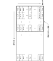
図2は、信号処理部17の機能的構成を示すブロック図である。信号処理部17は、受信信号用メモリ170、検出部171、および検出結果保持用メモリ172を備えている。受信信号用メモリ170は、A/D変換器16から入力される受信信号を保持する。
FIG. 2 is a block diagram showing a functional configuration of the
図3は、受信信号用メモリ170に保持される受信信号を示した図である。受信信号用メモリ170には、1回の測定(1ping)で得られる受信信号のデータが深度方向に所定分解能で(超音波の送信から所定時間経過毎に)順次保持されている。この例では、受信信号用メモリ170には、複数回の測定に対応するデータ列が保持されている。例えば最新の(今回の)測定においては、送信から受信までの時間差が最も小さい(最も深度の浅い)データがM(0,0)として保持され、深度方向の分解能に応じて、順にM(0,1)乃至M(0,n)として保持される。同様に、前回の測定については、最も深度の浅いデータがM(1,0)として保持され、深度方向の分解能に応じて、順にM(1,1)乃至M(1,n)として保持される。同様に、前々回の測定については、最も深度の浅いデータがM(2,0)として保持され、深度方向の分解能に応じて、順にM(2,1)乃至M(2,n)として保持される。
FIG. 3 is a diagram showing received signals held in the received
なお、同図の例では、今回、前回、前々回の3回分の測定のデータ列を保持する例を示しているが、保持するデータ列の数は、受信信号用メモリ170の容量に応じて順次設定すればよい。保持するデータ列の数以上に測定を行う場合は、最も古いデータ列から順に捨てられ、最新のデータ列が順次更新される。
In the example shown in the figure, an example is shown in which the data string of the measurement for the previous three times is held this time, but the number of data strings to be held is sequentially increased according to the capacity of the
次に、画像処理部18は、受信信号用メモリ170に保持された受信信号から表示部19に表示するためのエコー画像を生成する処理を行う。すなわち、画像処理部18は、受信信号用メモリ170に順次保持された各受信信号を、超音波を出力してからの経過時間に応じて、深度に対応したエコー画像に変換して画像処理部18に出力する処理を行う。
Next, the
図4(A)および図4(B)は、エコー画像の生成処理を示した図である。まず、画像処理部18は、受信信号用メモリ170から読み出した各受信信号を、表示部19の画素数(縦方向の画面解像度)に変換する処理を行う。この変換データが1回の測定(1ping)分のエコー画像となる。例えば、図4(A)に示すように、最新の測定に係る受信信号M(0,0)乃至M(0,n)のうち、M(0,0)およびM(0,1)を平均化し、最も深度の浅い位置に対応する画素のエコー画像f(0,0)とする。
FIGS. 4A and 4B are diagrams illustrating an echo image generation process. First, the
画像処理部18は、順に複数の受信信号を平均化して、各画素のエコー画像f(0,0)乃至f(0,m)を生成する。このようにして生成したエコー画像が最新の1ping分のエコー画像となる。なお、変換の態様は、図4(A)で示した例に限るものではない。例えば深度に応じて重み付け等を行ってもよいし、ピークホールド(最大値抽出)により変換を行ってもよい。
The
画像処理部18は、上記のようにして変換したエコー画像を画像メモリ181に保持する。画像メモリ181は、本発明のエコー画像保持部に相当する。画像メモリ181の内容は、1回の測定毎に更新される。したがって、画像メモリ181には、図4(B)に示すように、複数回の測定分のエコー画像が保持される。この例では、最も過去の測定に係るエコー画像f(l,0)乃至f(l,m)であり、最新の測定に係るエコー画像f(0,0)乃至f(0,m)である。画像メモリ181は、最も過去の測定に係るエコー画像(エコー画像f(l,0)乃至f(l,m))から、最新の測定に係るエコー画像(エコー画像f(l,0)乃至f(l,m))までのエコー画像を保持する。
The
そして、画像処理部18は、図5に示すように、画像メモリ181に保持されたエコー画像から、表示部19の1画面分(表示部19における縦方向および横方向の解像度分)のエコー画像を読み出し、表示部19に出力する。その結果、複数回分の測定のエコー画像が表示部19に表示される。
Then, as shown in FIG. 5, the
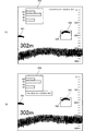
図6に示すように、表示部19には、横軸にping、縦軸に深度を割り当てたエコー画像が表示される。図6の例では、画面左端に魚群の一部のエコー画像201が表示され、画面中央右側に魚群のエコー画像200が表示されている。また、画面下側には海底のエコー画像が表示されている。
As shown in FIG. 6, the
さらに、図6の例では、海底検出処理の結果として海底深度(図中302mと示されたもの)、および魚群情報(図中のヒストグラム203)が表示される。
Further, in the example of FIG. 6, the seabed depth (shown as 302 m in the figure) and the fish school information (
海底深度および魚群情報は、信号処理部17における検出部171が出力する情報である。図2に示したように、検出部171は、受信信号用メモリ170から受信信号を読み出して解析し、魚群の検出および海底検出等の処理を行う。
The seabed depth and the school of fish information are information output by the
魚群の検出処理には、少なくとも魚体長の検出処理が含まれている。魚体長は、例えば所定閾値以上の受信信号を魚群とみなし、当該魚群の大きさ(サンプル数)、平均強度、または深度方向の長さ(平均長さ)等によって検出される。また、検出部171は、魚種の検出を行ってもよい。魚種は、例えば基準となる魚群のエコーとのマッチング度(類似度)によって判別する。
The fish school detection process includes at least a fish length detection process. The fish body length is detected based on the size (number of samples), the average intensity, or the length in the depth direction (average length) of the fish school, for example, when a received signal equal to or greater than a predetermined threshold is regarded as a fish school. Moreover, the
海底深度の検出は、例えば、ある閾値以上の受信信号を受信したタイミングを基準とする手法や、または微分値が最も高くなるタイミングを基準とする手法等を用いる。 The detection of the seabed depth uses, for example, a method based on the timing at which a received signal equal to or greater than a certain threshold is received, or a method based on the timing at which the differential value is the highest.
検出部171は、このようにして検出した各種情報(検出結果)を検出結果保持用メモリ(本発明の検出結果保持部に相当する。)172に保持する。このとき、検出結果は、解析した受信信号の測定タイミングの情報(例えば時刻)と対応付けて保持される。
The
また、制御部14は、検出部171に対して、表示部19の表示画面内で指定された領域(例えば図6の領域202)に対応する検出結果を出力するよう指示する。領域202の位置と大きさは、利用者が操作部10を操作することにより指定される。制御部14は、指定された領域202のエコー画像を取得したタイミング(測定タイミング)を示す情報を検出部171に出力する。
In addition, the
検出部171は、検出結果保持用メモリ172に保持されている検出結果から測定タイミングが一致する検出結果を読み出し、制御部14に出力する。制御部14は、検出部171から入力された検出結果を画像処理部18に出力する。画像処理部18は、制御部14から入力された検出結果をエコー画像に重畳して出力する。
The
これにより、表示部19の表示画面内には、検出結果として、例えば図6に示すヒストグラム203が表示される。ただし、検出結果の表示態様は、ヒストグラム203に限らず、例えば単に魚体長の数字を示すだけでもよい。なお、利用者が操作部10を操作して、ヒストグラム203に表示される魚体長のレンジを変更する操作を行った場合、画像処理部18は、表示する魚体長のレンジを変更する。すなわち、検出部171は、実際にヒストグラム203に表示されるレンジよりも広いレンジ分の検出結果を検出結果保持用メモリ172に保持している。利用者が魚体長のレンジを変更する操作を行った場合、画像処理部18は、指定されたレンジの結果情報のみ抽出し、エコー画像に重畳して出力する。
Thereby, for example, a
そして、利用者が、操作部10を操作して過去のエコー画像を表示させる操作を行ったとき、画像処理部18は、画像メモリ181から過去のエコー画像を読み出し、出力するエコー画像を連続的に変化させ、かつ、魚群の検出結果をエコー画像に重畳する。
When the user operates the
例えば、操作部10が回転摘まみを備えている場合、利用者が当該回転摘まみを回転させる操作を行うと、制御部14は、過去のエコー画像を表示させる操作として受け付ける。制御部14は、画像処理部18に対して、操作部10を介して受け付けた表示操作に追従して、表示されるエコー画像を連続的に変化させる。
For example, when the
例えば、図6の様な表示画面において、利用者が、左端に表示された魚群のエコー画像201を画面中央側に寄せるために、エコー画像を連続的に右側に移動させようとする操作(例えば回転摘まみを左回転させる操作)を行った場合について説明する。
For example, on the display screen as shown in FIG. 6, in order for the user to bring the
制御部14は、操作部10が回転摘まみを左回転させる操作を受け付けると、回転量に応じた時間分だけ過去のエコー画像を読み出すように、画像処理部18に指示する。画像処理部18は、図7に示すように、画像メモリ181から指示された時間分だけ過去のエコー画像を読み出し、出力するエコー画像を変化させる。これにより、表示部19に表示されるエコー画像は、回転摘まみの回転に応じて連続的に変化する。すなわち、利用者が回転摘まみを左回転させると、図8(A)に示すように、左端の魚群のエコー画像201が画面中央側に移動していく。
When the
このように、魚群探知機1は、利用者の表示操作に追従して過去のエコー画像を連続的に変化させて表示させる。また、この際、魚群の検出結果がエコー画像に重畳される。したがって、利用者が見たい魚群のエコー画像が画面から消えたり、目的の位置(例えば中央)に表示されなかったりすることがなく、利用者が目的の魚群の検出結果も同時に確認することが可能となる。
In this way, the
なお、上記「エコー画像を連続的に変化させる」とは、最小単位として、表示部19の表示画素のうち1画素ずつエコー画像を変化させることを意味する。無論、複数画素(例えば2画素)ずつ変化させることも連続的に変化させることに相当する。
Note that “continuously changing the echo image” means changing the echo image one pixel at a time among the display pixels of the
なお、図8(A)の例では、利用者が回転摘まみを回転させた場合でも、領域202は、表示画面内で指定された位置から変化しない。図8(A)の例では、領域202に魚群が検出されていないため、ヒストグラム203には何も表示されていない。しかし、例えば図8(B)に示すように、利用者がさらに回転摘まみを左回転させて、魚群のエコー画像201を領域202の内部まで移動させる操作を行った場合、当該魚群のエコー画像201の検出結果が検出結果保持用メモリ172から読み出される。したがって、ヒストグラム203には、魚群のエコー画像201の検出結果の情報が表示される。
In the example of FIG. 8A, even when the user rotates the rotary knob, the
次に、図9のフローチャートを参照して、魚群探知機1の動作について説明する。まず、魚群探知機1は、超音波の送受信を行う(s11)。そして、魚群探知機1は、受信信号の処理を行う(s12)。
Next, the operation of the
画像処理部18は、超音波を出力してからの経過時間に応じて、深度に対応したエコー画像を生成する(s13)。また、信号処理部17は、魚体長の検出処理を含む魚群検出処理を行う。
The
その後、画像処理部18は、生成したエコー画像を画像メモリ181に保持し(画像メモリ181の内容を更新する)、信号処理部17は、検出結果を検出結果保持用メモリ172に保持する(s14)。
Thereafter, the
一方、魚群探知機1は、操作部10から利用者が、操作部10を操作して過去のエコー画像を表示させる操作を行ったか否かを判断する(s21)。例えば、操作部10が回転摘まみを備えている場合、利用者が当該回転摘まみを回転させる操作を行うと、制御部14は、過去のエコー画像を表示させる操作として受け付ける。また、操作部10がカーソルキーを備えている場合、左または右方向のカーソルキーが押された場合に、操作部10は、過去のエコー画像を表示させる操作として受け付ける態様であってもよい。
On the other hand, the
画像処理部18は、過去のエコー画像を表示させる操作がない場合には、画像メモリ181に保持されたエコー画像から、表示部19の1画面分(表示部19における縦方向および横方向の解像度分)の最新のエコー画像を読み出す(s22)。
When there is no operation for displaying a past echo image, the
一方で、画像処理部18は、利用者が操作部10を操作して過去のエコー画像を表示させる操作を行った場合、表示操作に対応するエコー画像を画像メモリ181から読み出す(s23)。このとき画像メモリ181は、操作部10で受け付けた表示操作(回転摘まみの回転)に追従して、画像メモリ181から読み出すエコー画像を変化させることで、表示されるエコー画像を連続的に変化させる。したがって、エコー画像は、回転摘まみの回転量に応じて連続的に変化する(s23)。例えば、図6の状態から、利用者が回転摘まみを左回転させると、左端の魚群のエコー画像201は、図8(A)に示す状態まで、連続的に画面中央側に移動していく。これにより、利用者は、見たい魚群のエコー画像を視認しながら、目的の位置(例えば中央)まで移動させて表示させることができる。さらに、図8(A)の状態から、利用者が回転摘まみを左回転させると、魚群のエコー画像は、図8(B)に示すように画面右側に移動していく。そして、魚群のエコー画像201が領域202の内部まで移動した場合、当該魚群のエコー画像201の検出結果が検出結果保持用メモリ172から読み出される。
On the other hand, when the user operates the
次に、図10は、応用例に係る魚群探知機1Aの構成を示すブロック図である。図1と共通する構成については同一の符号を付し、説明を省略する。魚群探知機1Aは、さらに位置情報検出部50を備えている。
Next, FIG. 10 is a block diagram showing a configuration of a
位置情報検出部50は、例えばGPSを備えている。制御部14は、超音波の送受信毎に位置情報検出部50から位置情報(緯度および経度情報)を受信し、測定タイミング毎に位置情報を位置情報メモリ(不図示)に保持する。位置情報は、測定タイミングを示す情報(例えば時刻)とともに保持される。
The position
画像処理部18は、制御部14から最新の位置情報を読み出し、例えば図11(A)に示すように、表示部19の画面内の所定の位置に表示させる。
The
また、画像処理部18は、図11(B)に示すように、利用者が操作部10で指定された領域202のエコー画像を取得した測定タイミング(例えば領域202の右端の測定タイミング)に対応する位置情報を制御部14から取得し、検出結果(ヒストグラム203)とともに表示してもよい。無論、画像処理部18は、最新の測定タイミングにおける位置情報と、指定された領域202のエコー画像を取得した測定タイミングに対応する位置情報と、を両方表示してもよい。
Further, as shown in FIG. 11B, the
そして、利用者が操作部10を操作して、過去のエコー画像を表示させる操作を行ったとき、画像処理部18は、操作部10を介して受け付けた表示操作に追従して、制御部14から取得する位置情報を変化させる。画像処理部18は、例えば表示部19における現在の画面内の右端のエコー画像を取得した測定タイミングに対応する位置情報を取得し、表示させる。また、画像処理部18は、指定された領域202のエコー画像を取得した測定タイミングに対応する位置情報を表示する場合も、同様に、対応する位置情報を制御部14から取得し、表示させる。
Then, when the user operates the
なお、画像処理部18は、利用者が操作部10を操作して位置情報を入力した場合に、当該入力された位置情報に対応するエコー画像を画像メモリ181から読み出して、表示部19に表示させるようにしてもよい。これにより、利用者は、例えば過去に通過した漁場の位置を知っている場合に、当該漁場を通過した時の水中の状況を見直すことができる。
When the user operates the
また、LAN等の通信機能を介して魚群探知機1がプロッタに接続されている場合、魚群探知機1は、利用者にプロッタ上で指定された位置のエコー画像を表示する態様としてもよい。この場合、位置情報検出部50は、別途プロッタに備えられていて、当該プロッタが位置情報を取得するようにしてもよいし、魚群探知機1Aとプロッタとで同じ位置情報検出部50を用いて、位置情報を共有するようにしてもよい。これにより、利用者は、過去に通過した漁場の位置をプロッタ上で指定するだけで、当該漁場を通過した時の水中の状況を見直すことができる。
In addition, when the
1,1A…魚群探知機
10…操作部
11…送受波器
12…送受切替部
13…送信回路
14…制御部
15…受信回路
16…A/D変換器
17…信号処理部
18…画像処理部
19…表示部
50…位置情報検出部
170…受信信号用メモリ
171…検出部
172…検出結果保持用メモリ
181…画像メモリ
200,201…エコー画像
202…領域
203…ヒストグラム
DESCRIPTION OF
Claims (8)
前記送受波器が受信した受信信号に基づいてエコー画像を生成する画像処理部と、
前記エコー画像を保持するエコー画像保持部と、
前記エコー画像保持部に保持されたエコー画像を変化させる表示操作を受け付ける受付部と、
前記送受波器が受信した受信信号に基づいて魚群の検出を行う検出部と、
前記検出部の検出結果を保持する検出結果保持部と、を備え、
前記画像処理部は、前記表示操作に追従して、前記エコー画像保持部から過去のエコー画像を読み出し、出力するエコー画像を連続的に変化させ、かつ、前記検出結果を前記エコー画像に重畳することを特徴とする魚群探知機。 A transducer for transmitting and receiving ultrasound,
An image processing unit that generates an echo image based on a received signal received by the transducer;
An echo image holding unit for holding the echo image;
A receiving unit for receiving a display operation for changing the echo image held in the echo image holding unit;
A detector for detecting a school of fish based on the received signal received by the transducer;
A detection result holding unit for holding a detection result of the detection unit,
The image processing unit follows the display operation, reads past echo images from the echo image holding unit, continuously changes the output echo images, and superimposes the detection results on the echo images. A fish finder characterized by that.
前記検出部は、前記魚群の魚体長を含む情報を検出することを特徴とする魚群探知機。 The fish finder according to claim 1,
The fish detector according to claim 1, wherein the detection unit detects information including a fish body length of the fish school.
前記エコー画像を表示する表示部と、をさらに備え、
前記受付部は、前記表示部に表示されているエコー画像のうち、前記魚群の検出を行う領域の指定を受け付け、
前記エコー画像に重畳される検出結果は、前記受付部で指定された領域に対応する検出結果が、前記検出結果保持部から読み出されたものであることを特徴とする魚群探知機。 In the fish finder according to claim 1 or 2,
A display unit for displaying the echo image,
The reception unit receives designation of a region for detecting the fish school in the echo image displayed on the display unit,
The fish detector according to claim 1, wherein the detection result superimposed on the echo image is a detection result corresponding to an area designated by the reception unit read from the detection result holding unit.
前記領域は、前記表示操作が連続的に変化した場合にも、前記表示部の表示画面内で指定された位置に配置されていることを特徴とする魚群探知機。 The fish finder according to claim 3,
The fish finder is characterized in that the area is arranged at a designated position in the display screen of the display unit even when the display operation is continuously changed.
位置情報を検出する位置情報検出部をさらに備え、
前記エコー画像は、前記位置情報と対応付けられて前記エコー画像保持部に保持されていることを特徴とする魚群探知機。 In the fish finder according to any one of claims 1 to 4,
A position information detecting unit for detecting position information;
The fish detector according to claim 1, wherein the echo image is stored in the echo image storage unit in association with the position information.
前記受付部は、位置の指定を受け付け、
前記画像処理部は、指定された位置に対応するエコー画像を変化させることを特徴とする魚群探知機。 The fish finder according to claim 5,
The reception unit receives a designation of a position,
The fish finder, wherein the image processing unit changes an echo image corresponding to a designated position.
前記送受波器が受信した受信信号に基づいてエコー画像を生成する画像処理部と、
前記エコー画像を保持するエコー画像保持部と、
前記エコー画像保持部に保持されたエコー画像を変化させる表示操作を受け付ける受付部と、
前記送受波器が受信した受信信号に基づいて魚群の検出を行う検出部と、
前記検出部の検出結果を保持する検出結果保持部と、を備え、
前記画像処理部に、前記表示操作に追従して、前記エコー画像保持部から過去のエコー画像を読み出し、出力するエコー画像を連続的に変化させ、かつ、前記検出結果を前記エコー画像に重畳する処理を実行させることを特徴とするプログラム。 A transducer for transmitting and receiving ultrasound,
An image processing unit that generates an echo image based on a received signal received by the transducer;
An echo image holding unit for holding the echo image;
A receiving unit for receiving a display operation for changing the echo image held in the echo image holding unit;
A detector for detecting a school of fish based on the received signal received by the transducer;
A detection result holding unit for holding a detection result of the detection unit,
Following the display operation, the image processing unit reads past echo images from the echo image holding unit, continuously changes the output echo images, and superimposes the detection results on the echo images. A program characterized by causing processing to be executed.
前記送受波ステップで受信した受信信号に基づいてエコー画像を生成する画像処理ステップと、
前記エコー画像を保持するエコー画像保持ステップと、
前記エコー画像を保持するエコー画像保持ステップと、
前記エコー画像保持ステップにおいて保持されたエコー画像を変化させる表示操作を受け付ける受付ステップと、
前記送受波器が受信した受信信号に基づいて魚群の検出を行う検出ステップと、
前記検出ステップにおける前記魚群の検出結果を保持する検出結果保持ステップと、
を備え、
前記画像処理ステップは、前記表示操作に追従して、前記エコー画像保持ステップで保持した過去のエコー画像を読み出し、出力するエコー画像を連続的に変化させ、かつ、前記検出結果を前記エコー画像に重畳することを特徴とする魚群探知方法。 A transmission and reception step for transmitting and receiving ultrasonic waves;
An image processing step for generating an echo image based on the received signal received in the transmitting and receiving step;
An echo image holding step for holding the echo image;
An echo image holding step for holding the echo image;
A receiving step for receiving a display operation for changing the echo image held in the echo image holding step;
A detection step of detecting a school of fish based on the received signal received by the transducer;
A detection result holding step for holding a detection result of the fish school in the detection step;
With
In the image processing step, following the display operation, the past echo image held in the echo image holding step is read, the echo image to be output is continuously changed, and the detection result is converted into the echo image. A fish detection method characterized by superimposing.
Priority Applications (3)
| Application Number | Priority Date | Filing Date | Title |
|---|---|---|---|
| JP2015135118A JP6554345B2 (en) | 2015-07-06 | 2015-07-06 | Fish detector, program and method for detecting fish |
| GB1611570.1A GB2540272B (en) | 2015-07-06 | 2016-07-01 | Method of detecting school of fish, program and fish finder |
| CN201610527700.5A CN106338734B (en) | 2015-07-06 | 2016-07-06 | Fish shoal detection machine, fish shoal detection system, and fish shoal detection method |
Applications Claiming Priority (1)
| Application Number | Priority Date | Filing Date | Title |
|---|---|---|---|
| JP2015135118A JP6554345B2 (en) | 2015-07-06 | 2015-07-06 | Fish detector, program and method for detecting fish |
Publications (2)
| Publication Number | Publication Date |
|---|---|
| JP2017015645A true JP2017015645A (en) | 2017-01-19 |
| JP6554345B2 JP6554345B2 (en) | 2019-07-31 |
Family
ID=56891217
Family Applications (1)
| Application Number | Title | Priority Date | Filing Date |
|---|---|---|---|
| JP2015135118A Active JP6554345B2 (en) | 2015-07-06 | 2015-07-06 | Fish detector, program and method for detecting fish |
Country Status (3)
| Country | Link |
|---|---|
| JP (1) | JP6554345B2 (en) |
| CN (1) | CN106338734B (en) |
| GB (1) | GB2540272B (en) |
Families Citing this family (2)
| Publication number | Priority date | Publication date | Assignee | Title |
|---|---|---|---|---|
| WO2019043931A1 (en) * | 2017-09-01 | 2019-03-07 | 本多電子株式会社 | Nautical chart image display device |
| JP7021025B2 (en) * | 2018-07-31 | 2022-02-16 | 古野電気株式会社 | Echo signal processing device, echo signal processing system, and echo signal processing method |
Citations (14)
| Publication number | Priority date | Publication date | Assignee | Title |
|---|---|---|---|---|
| JPS571979A (en) * | 1980-06-05 | 1982-01-07 | Koden Electronics Co Ltd | Fish amount indicator |
| JPS58174872A (en) * | 1981-12-09 | 1983-10-13 | Furuno Electric Co Ltd | Underwater detection display |
| JPH01152383A (en) * | 1987-12-09 | 1989-06-14 | Japan Radio Co Ltd | Fish-finder |
| US5184330A (en) * | 1991-06-25 | 1993-02-02 | Techsonic Industries, Inc. | Multi-beam sonar fish detection apparatus providing real-time three-dimensional wire-frame display representation |
| JPH0843531A (en) * | 1994-08-02 | 1996-02-16 | Japan Radio Co Ltd | Fishfinder |
| JP2000152168A (en) * | 1998-11-13 | 2000-05-30 | Olympus Optical Co Ltd | Image reproducing device |
| JP2001159677A (en) * | 1999-12-03 | 2001-06-12 | Furuno Electric Co Ltd | Underwater detecting device and sounding device |
| JP2005249398A (en) * | 2004-03-01 | 2005-09-15 | Furuno Electric Co Ltd | Metering fish finder and fish body length metering method |
| JP2008224501A (en) * | 2007-03-14 | 2008-09-25 | Royal Kogyo Kk | Fish finder, and measurement information display method of fish finder |
| US7663974B2 (en) * | 2006-10-02 | 2010-02-16 | Furuno Electric Company Limited | Fishfinder |
| JP2012026855A (en) * | 2010-07-23 | 2012-02-09 | Furuno Electric Co Ltd | Hydrospace detection apparatus, fish shoal detection apparatus, hydrospace detection method, and fish shoal detection method |
| JP2014002084A (en) * | 2012-06-20 | 2014-01-09 | Furuno Electric Co Ltd | Underwater detection device, underwater display system, program and underwater display method |
| US20150029824A1 (en) * | 2013-07-23 | 2015-01-29 | The Boeing Company | Fish Tracker |
| JP2015121447A (en) * | 2013-12-24 | 2015-07-02 | 公立大学法人公立はこだて未来大学 | Terminal, fish school detection system, fish school display method, and fish school display program |
Family Cites Families (10)
| Publication number | Priority date | Publication date | Assignee | Title |
|---|---|---|---|---|
| JPS63210682A (en) * | 1987-02-27 | 1988-09-01 | Japan Radio Co Ltd | Water temperature display system for fish finder |
| JP3429362B2 (en) * | 1994-04-13 | 2003-07-22 | 株式会社不二ロイヤル | Fish finder |
| JP3529006B2 (en) * | 1996-09-30 | 2004-05-24 | 株式会社光電製作所 | Fish finder |
| JPH11344566A (en) * | 1998-03-31 | 1999-12-14 | Japan Radio Co Ltd | Fish finder |
| JP4518828B2 (en) * | 2004-04-07 | 2010-08-04 | 古野電気株式会社 | Weighing fish finder and measuring fish finder |
| US20080192575A1 (en) * | 2007-02-14 | 2008-08-14 | Navico Inc. | Method, Apparatus and Computer Program Product for Providing a Sonar History |
| JP5286163B2 (en) * | 2009-06-05 | 2013-09-11 | 古野電気株式会社 | Fish finder |
| JP6251474B2 (en) * | 2012-12-12 | 2017-12-20 | 古野電気株式会社 | Underwater detection device and target display method |
| CN103760550B (en) * | 2014-01-20 | 2016-03-30 | 南京宁禄科技有限公司 | Handheld depth finder/fish detector/transducer tester |
| CN104749567B (en) * | 2015-04-20 | 2017-03-08 | 上海海事大学 | Sonar target echo simulation system is visited in a kind of amphibian fishing |
-
2015
- 2015-07-06 JP JP2015135118A patent/JP6554345B2/en active Active
-
2016
- 2016-07-01 GB GB1611570.1A patent/GB2540272B/en active Active
- 2016-07-06 CN CN201610527700.5A patent/CN106338734B/en active Active
Patent Citations (15)
| Publication number | Priority date | Publication date | Assignee | Title |
|---|---|---|---|---|
| JPS571979A (en) * | 1980-06-05 | 1982-01-07 | Koden Electronics Co Ltd | Fish amount indicator |
| JPS58174872A (en) * | 1981-12-09 | 1983-10-13 | Furuno Electric Co Ltd | Underwater detection display |
| JPH01152383A (en) * | 1987-12-09 | 1989-06-14 | Japan Radio Co Ltd | Fish-finder |
| JP2567641B2 (en) * | 1987-12-09 | 1996-12-25 | 日本無線株式会社 | Fish finder |
| US5184330A (en) * | 1991-06-25 | 1993-02-02 | Techsonic Industries, Inc. | Multi-beam sonar fish detection apparatus providing real-time three-dimensional wire-frame display representation |
| JPH0843531A (en) * | 1994-08-02 | 1996-02-16 | Japan Radio Co Ltd | Fishfinder |
| JP2000152168A (en) * | 1998-11-13 | 2000-05-30 | Olympus Optical Co Ltd | Image reproducing device |
| JP2001159677A (en) * | 1999-12-03 | 2001-06-12 | Furuno Electric Co Ltd | Underwater detecting device and sounding device |
| JP2005249398A (en) * | 2004-03-01 | 2005-09-15 | Furuno Electric Co Ltd | Metering fish finder and fish body length metering method |
| US7663974B2 (en) * | 2006-10-02 | 2010-02-16 | Furuno Electric Company Limited | Fishfinder |
| JP2008224501A (en) * | 2007-03-14 | 2008-09-25 | Royal Kogyo Kk | Fish finder, and measurement information display method of fish finder |
| JP2012026855A (en) * | 2010-07-23 | 2012-02-09 | Furuno Electric Co Ltd | Hydrospace detection apparatus, fish shoal detection apparatus, hydrospace detection method, and fish shoal detection method |
| JP2014002084A (en) * | 2012-06-20 | 2014-01-09 | Furuno Electric Co Ltd | Underwater detection device, underwater display system, program and underwater display method |
| US20150029824A1 (en) * | 2013-07-23 | 2015-01-29 | The Boeing Company | Fish Tracker |
| JP2015121447A (en) * | 2013-12-24 | 2015-07-02 | 公立大学法人公立はこだて未来大学 | Terminal, fish school detection system, fish school display method, and fish school display program |
Also Published As
| Publication number | Publication date |
|---|---|
| CN106338734A (en) | 2017-01-18 |
| GB2540272A (en) | 2017-01-11 |
| JP6554345B2 (en) | 2019-07-31 |
| CN106338734B (en) | 2021-11-26 |
| GB2540272B (en) | 2020-01-08 |
| GB201611570D0 (en) | 2016-08-17 |
Similar Documents
| Publication | Publication Date | Title |
|---|---|---|
| JP6014382B2 (en) | Underwater detection device, underwater display system, program, and underwater display method | |
| AU2019203322B2 (en) | Marine electronic device for presentment of nautical charts and sonar images | |
| JP2019120543A (en) | Target detection device | |
| JP2007064768A (en) | Underwater detection system | |
| JP6059867B2 (en) | Ultrasonic detection device, ultrasonic detection method, ultrasonic detection program | |
| JP2014048103A (en) | Object detection device and echo data display method in object detection device | |
| JP2008128900A (en) | Echo image display apparatus | |
| JP6251474B2 (en) | Underwater detection device and target display method | |
| JP2008268183A (en) | Underwater detection device | |
| US9182488B2 (en) | Method and device for detecting target object | |
| JP6554345B2 (en) | Fish detector, program and method for detecting fish | |
| US20170363739A1 (en) | Adjustable range viewing of sonar imagery during trip replay | |
| JP2012247320A (en) | Video display device and radar device | |
| WO2004099815A1 (en) | Ultrasonic wave transmitter/receiver | |
| JP2017166880A (en) | Acoustic measuring device, acoustic measuring method, multi-beam acoustic measuring device, and synthetic aperture sonar | |
| JP7163555B2 (en) | Underwater information visualization device | |
| JP2016038323A (en) | Detection device, detection method, and program | |
| US20200292701A1 (en) | Wading staff with a sonar transducer | |
| JP2016090348A (en) | Sensor remote control system, remote operation device, sensor device and sensor remote control method | |
| CN110780286A (en) | Echo signal processing device and system, and echo signal processing method | |
| JP6240671B2 (en) | Sensor information output device, sensor video display device, detection device, and sensor information output method | |
| JP4796777B2 (en) | Underwater detector | |
| JP2015165245A (en) | Apparatus and method for target detection | |
| JP5023206B2 (en) | Underwater detector | |
| JP2017067713A (en) | Underwater detection device |
Legal Events
| Date | Code | Title | Description |
|---|---|---|---|
| A621 | Written request for application examination |
Free format text: JAPANESE INTERMEDIATE CODE: A621 Effective date: 20180410 |
|
| A977 | Report on retrieval |
Free format text: JAPANESE INTERMEDIATE CODE: A971007 Effective date: 20181114 |
|
| A131 | Notification of reasons for refusal |
Free format text: JAPANESE INTERMEDIATE CODE: A131 Effective date: 20181120 |
|
| A521 | Request for written amendment filed |
Free format text: JAPANESE INTERMEDIATE CODE: A523 Effective date: 20190109 |
|
| TRDD | Decision of grant or rejection written | ||
| A01 | Written decision to grant a patent or to grant a registration (utility model) |
Free format text: JAPANESE INTERMEDIATE CODE: A01 Effective date: 20190702 |
|
| A61 | First payment of annual fees (during grant procedure) |
Free format text: JAPANESE INTERMEDIATE CODE: A61 Effective date: 20190708 |
|
| R150 | Certificate of patent or registration of utility model |
Ref document number: 6554345 Country of ref document: JP Free format text: JAPANESE INTERMEDIATE CODE: R150 |
|
| R250 | Receipt of annual fees |
Free format text: JAPANESE INTERMEDIATE CODE: R250 |