JP2017015250A - Manual transmission - Google Patents
Manual transmission Download PDFInfo
- Publication number
- JP2017015250A JP2017015250A JP2016104407A JP2016104407A JP2017015250A JP 2017015250 A JP2017015250 A JP 2017015250A JP 2016104407 A JP2016104407 A JP 2016104407A JP 2016104407 A JP2016104407 A JP 2016104407A JP 2017015250 A JP2017015250 A JP 2017015250A
- Authority
- JP
- Japan
- Prior art keywords
- gear
- power transmission
- side power
- transmission shaft
- shaft
- Prior art date
- Legal status (The legal status is an assumption and is not a legal conclusion. Google has not performed a legal analysis and makes no representation as to the accuracy of the status listed.)
- Granted
Links
- 230000005540 biological transmission Effects 0.000 title claims abstract description 397
- 230000006866 deterioration Effects 0.000 abstract description 5
- 230000007935 neutral effect Effects 0.000 description 9
- 230000000694 effects Effects 0.000 description 3
- 230000002093 peripheral effect Effects 0.000 description 3
- 238000000746 purification Methods 0.000 description 3
- 230000007423 decrease Effects 0.000 description 2
- 238000004519 manufacturing process Methods 0.000 description 2
- 230000001360 synchronised effect Effects 0.000 description 2
- 230000001133 acceleration Effects 0.000 description 1
- 239000003054 catalyst Substances 0.000 description 1
- 238000010586 diagram Methods 0.000 description 1
- 238000012986 modification Methods 0.000 description 1
- 230000004048 modification Effects 0.000 description 1
Images


Landscapes
- Structure Of Transmissions (AREA)
Abstract
Description
本発明は、車両に搭載される手動変速機に関する技術分野に属する。 The present invention belongs to a technical field related to a manual transmission mounted on a vehicle.
一般に、車両の前部に位置するエンジンルーム内にエンジンを配置しかつ該エンジンにより後輪を駆動するフロントエンジン・リヤドライブ車(FR車)又は該FR車をベースとする四輪駆動車の場合、エンジンルーム内において、エンジン及び変速機が縦置き配置される。すなわち、エンジンの出力軸(クランク軸)及び変速機の動力伝達軸が車両前後方向に延びるようにエンジン及び変速機が配置される。 Generally, in the case of a four-wheel drive vehicle based on a front engine / rear drive vehicle (FR vehicle) in which an engine is disposed in an engine room located in the front part of the vehicle and the rear wheels are driven by the engine. In the engine room, the engine and the transmission are vertically arranged. That is, the engine and the transmission are arranged such that the output shaft (crank shaft) of the engine and the power transmission shaft of the transmission extend in the vehicle front-rear direction.
前記変速機が手動変速機である場合、この手動変速機は、一般に、一端部がエンジンにクラッチを介して連結される入力側動力伝達軸と、駆動輪にデファレンシャル機構等を介して連結され、前記入力側動力伝達軸と同一軸線上に配置された出力側動力伝達軸と、前記入力側動力伝達軸(及び前記出力側動力伝達軸)に平行に配置されたカウンタ軸及びリバース軸とを備えている。前記入力側動力伝達軸と前記カウンタ軸との間には、複数の前進変速段用ギヤ列が設けられており、各前進変速段用ギヤ列は、前記入力側動力伝達軸上及び前記カウンタ軸上にそれぞれ配置されかつ互いに噛合う一組のギヤを有している。また、前記入力側動力伝達軸と前記カウンタ軸と前記リバース軸との間には、リバース用ギヤ列が設けられており、このリバース用ギヤ列は、前記入力側動力伝達軸上、前記カウンタ軸上及び前記リバース軸上にそれぞれ配置されかつ互いに噛合う一組のギヤを有している。さらに、前記カウンタ軸と前記出力側動力伝達軸との間には、前記カウンタ軸の回転を減速して前記出力側動力伝達軸に出力する減速ギヤ列が設けられており、この減速ギヤ列は、前記カウンタ軸上及び前記出力側動力伝達軸上にそれぞれ配置されかつ互いに噛合う一組のギヤを有している。このように、入力側動力伝達軸とカウンタ軸との間に、リバース用ギヤ列を含む複数の変速段用ギヤ列が配置され、カウンタ軸から減速機構(減速ギヤ列)を介して出力側動力伝達軸に動力が伝達される手動変速機は、アウトプットリダクションタイプの手動変速機と呼ばれる。そして、車両の乗員(ドライバ)のチェンジレバーの操作により、変速操作機構を介して、前記複数の前進変速段用ギヤ列及びリバース用ギヤ列のうちのいずれか1つのギヤ列が動力伝達状態とされる。 When the transmission is a manual transmission, the manual transmission is generally connected to an input side power transmission shaft having one end connected to an engine via a clutch, and to a drive wheel via a differential mechanism, An output-side power transmission shaft disposed on the same axis as the input-side power transmission shaft; and a counter shaft and a reverse shaft disposed in parallel to the input-side power transmission shaft (and the output-side power transmission shaft). ing. A plurality of forward speed gear trains are provided between the input side power transmission shaft and the counter shaft, and each forward speed gear train is arranged on the input side power transmission shaft and the counter shaft. It has a set of gears which are arranged on each other and mesh with each other. Further, a reverse gear train is provided between the input-side power transmission shaft, the counter shaft, and the reverse shaft, and the reverse gear train is arranged on the input-side power transmission shaft and the counter shaft. A pair of gears are disposed on the upper and reverse shafts and mesh with each other. Furthermore, a reduction gear train that decelerates the rotation of the counter shaft and outputs it to the output power transmission shaft is provided between the counter shaft and the output power transmission shaft. And a pair of gears arranged on the counter shaft and the output side power transmission shaft and meshing with each other. As described above, a plurality of gear stages for the shift stage including the reverse gear train are arranged between the input-side power transmission shaft and the counter shaft, and the output-side power from the counter shaft via the speed reduction mechanism (reduction gear train). A manual transmission in which power is transmitted to the transmission shaft is called an output reduction type manual transmission. Then, by operating a change lever of a vehicle occupant (driver), any one of the plurality of forward shift gear trains and the reverse gear train is brought into a power transmission state via a shift operation mechanism. Is done.
また、例えば6段の前進変速段を有する手動変速機(最高変速段が6速である手動変速機)として、5速を、減速比が1となる直結変速段とする5速直結タイプの手動変速機が知られている。このものは、5速において、前記入力側動力伝達軸と前記出力側動力伝達軸とを、前記複数の前進変速段用ギヤ列を介さずに直結した状態にする。この5速直結タイプでは、6速においては、減速比が1よりも小さくなる。 Further, for example, as a manual transmission having six forward shift speeds (manual transmission having a maximum gear shift of 6 speeds), a 5-speed direct connection type manual operation in which the 5th speed is a directly connected shift speed having a reduction ratio of 1 is used. A transmission is known. In the fifth gear, the input-side power transmission shaft and the output-side power transmission shaft are directly connected without using the plurality of forward gear stages. In the 5-speed direct connection type, the reduction ratio is smaller than 1 at the sixth speed.
近年では、最高変速段で減速比を1とする(最高変速段を直結変速段とする)手動変速機も知られている(例えば特許文献1参照)。尚、特許文献1では、カウンタ軸は設けられておらず、入力側動力伝達軸と出力側動力伝達軸との間に、複数の前進変速段用ギヤ列が設けられ、前記入力側動力伝達軸と前記出力側動力伝達軸とリバース軸との間に、リバース用ギヤ列が設けられている。
In recent years, a manual transmission in which the reduction gear ratio is 1 at the highest gear (the highest gear is a direct-coupled gear) is also known (see, for example, Patent Document 1). In
6段の前進変速段を有する手動変速機で、最高変速段を直結変速段とする場合には、6速直結タイプとなる。この6速直結タイプの場合、5速直結タイプに比べて、減速比が1よりも大きな変速段の数が多くなり、この結果、両タイプで変速段間のギヤステップを揃えると、6速直結タイプの方が1速の減速比を大きくすることができるので、より強力な発進加速性が得られる。また、6速直結タイプの場合、減速比が1よりも大きな領域での、車両の乗員の変速段選択の自由度が高まる。したがって、5速直結タイプから6速直結タイプへ変更することで、スポーティな走行性を実現することができる。 In the case of a manual transmission having 6 forward shift speeds and the highest shift speed being a direct shift speed, a 6-speed direct link type is used. In this 6-speed direct connection type, the number of gears with a reduction ratio larger than 1 is larger than that in the 5-speed direct connection type. As a result, if both types have the same gear steps between the gears, the 6-speed direct connection type Since the type can increase the reduction ratio of the first gear, a stronger start acceleration can be obtained. Further, in the case of the 6-speed direct connection type, the degree of freedom in selecting the gear position of the vehicle occupant in the region where the reduction ratio is larger than 1 is increased. Therefore, by changing from the 5-speed direct connection type to the 6-speed direct connection type, sporty running performance can be realized.
ところが、6速直結タイプの場合、前記のように減速比が大きくなるために、5速直結タイプに比べて前記前進変速段用ギヤ列のギヤ及び同期装置の伝達トルクが全般的に大きくなるとともに、前記入力側動力伝達軸及び前記カウンタ軸を支持する軸受の負荷も大きくなる。この結果、前記入力側動力伝達軸及び前記カウンタ軸並びに軸受の径方向及び軸方向の寸法が増大して、手動変速機の大型化を招くこととなる。 However, in the case of the 6-speed direct connection type, the reduction ratio is increased as described above, and therefore the transmission torque of the gear of the forward gear stage and the synchronizer is generally increased as compared with the 5-speed direct connection type. The load on the bearing that supports the input-side power transmission shaft and the counter shaft also increases. As a result, the input-side power transmission shaft, the counter shaft, and the radial and axial dimensions of the bearing are increased, leading to an increase in the size of the manual transmission.
ここで、手動変速機としては、前記アウトプットリダクションタイプの手動変速機以外に、入力側動力伝達軸から減速機構(減速ギヤ列)を介してカウンタ軸に動力が伝達され、カウンタ軸と出力側動力伝達軸との間に、リバース用ギヤ列を含む複数の変速段用ギヤ列(減速ギヤ列に限らない)が配置された、いわゆるインプットリダクションタイプの手動変速機が知られている。インプットリダクションタイプであってもアウトプットリダクションタイプであっても、直結変速段では、入力側動力伝達軸と出力側動力伝達軸とが係合(直結)されることになる。 Here, as the manual transmission, in addition to the output reduction type manual transmission, power is transmitted from the input side power transmission shaft to the counter shaft via the speed reduction mechanism (deceleration gear train), and the counter shaft and the output side There is known a so-called input reduction type manual transmission in which a plurality of shift speed gear trains (not limited to a reduction gear train) including a reverse gear train are disposed between a power transmission shaft. Regardless of the input reduction type or the output reduction type, the input-side power transmission shaft and the output-side power transmission shaft are engaged (directly coupled) at the direct connection speed.
前記インプットリダクションタイプの場合、入力側動力伝達軸から減速機構を介してカウンタ軸に動力が伝達されるために、カウンタ軸に伝達されるトルクが相対的に大きくなり、このため、各変速段用ギヤ列のギヤに発生する力が大きくなる。この力に耐え得るように、特にカウンタ軸を支持する軸受を大型化する必要があるとともに、各変速段用ギヤ列のギヤを大型化してカウンタ軸と出力側動力伝達軸との軸間距離を広げる必要があるので、結果として、手動変速機全体が大型化する。 In the case of the input reduction type, since the power is transmitted from the input side power transmission shaft to the counter shaft via the speed reduction mechanism, the torque transmitted to the counter shaft becomes relatively large. The force generated in the gear train is increased. In order to withstand this force, it is necessary to increase the size of the bearing that supports the countershaft in particular, and the gears of the gear trains for each shift stage are increased in size so that the distance between the countershaft and the output-side power transmission shaft is increased. As a result, it is necessary to widen the entire manual transmission.
これに対し、前記アウトプットリダクションタイプの場合、カウンタ軸に伝達されるトルクは相対的に小さいため、各変速段用ギヤ列のギヤに発生する力が小さくなる。この結果、各変速段用ギヤ列のギヤ、入力側動力伝達軸及びカウンタ軸を支持する軸受、同期装置のスプライン等を小型化することができるので、手動変速機全体を小型化することができる。 On the other hand, in the output reduction type, the torque transmitted to the counter shaft is relatively small, so that the force generated in the gears of each gear stage is small. As a result, the gear of each gear stage, the bearings supporting the input-side power transmission shaft and the counter shaft, the splines of the synchronizer and the like can be reduced in size, so that the entire manual transmission can be reduced in size. .
また、車両の乗員のチェンジレバーの操作時において、前記インプットリダクションタイプの場合には、出力側動力伝達軸に、入力側動力伝達軸と共に回転するカウンタ軸を同期させる必要があるのに対して、前記アウトプットリダクションタイプの場合には、カウンタ軸に入力側動力伝達軸を同期させればよい。そのため、アウトプットリダクションタイプの場合には、インプットリダクションタイプの場合に比べて、同期させる対象となる回転軸のイナーシャが小さくなるので、車両の乗員がチェンジレバーをシフト操作する際の操作力を低減することができる。したがって、6速直結タイプの手動変速機の実現に当たっては、前記アウトプットリダクションタイプを採用することが望まれる。 In the case of the input reduction type, when operating the change lever of the vehicle occupant, it is necessary to synchronize the counter shaft rotating with the input side power transmission shaft to the output side power transmission shaft, In the case of the output reduction type, the input side power transmission shaft may be synchronized with the counter shaft. Therefore, in the case of the output reduction type, the inertia of the rotating shaft to be synchronized is smaller than in the case of the input reduction type, so the operation force when the vehicle occupant shifts the change lever is reduced. can do. Therefore, it is desirable to adopt the output reduction type when realizing a 6-speed direct connection type manual transmission.
しかしながら、6速直結タイプでアウトプットリダクションタイプの手動変速機を実現しようとする場合、特に、リバース用ギヤ列及び前進変速段用ギヤ列の配置を具体的にどのようにすることが望ましいかという課題がある。例えば特許文献1に記載された6速直結タイプの手動変速機をアウトプットリダクションタイプに変更しようとした場合、特許文献1の出力側動力伝達軸をそのままカウンタ軸とし、入力側動力伝達軸の反エンジン側において、該入力側動力伝達軸と同一軸線上に新たな出力側動力伝達軸を設ける。特許文献1の手動変速機では、リバース用ギヤ列が最も反エンジン側に配置されているが、6速において入力側動力伝達軸と新たな出力側動力伝達軸とを係合(直結)した6速直結を実現するためには、5速用ギヤ列をリバース用ギヤ列の反エンジン側に配置して、5速用ギヤ列の反エンジン側に、5−6速用同期装置を配置する必要がある。この結果、リバース用ギヤ列及び前進変速段用ギヤ列の並びは、エンジン側から、2速用ギヤ列、1速用ギヤ列、4速用ギヤ列、3速用ギヤ列、リバース用ギヤ列、5速用ギヤ列の順となる。
However, when a 6-speed direct connection type output reduction type manual transmission is to be realized, it is particularly desirable to specifically arrange the reverse gear train and the forward gear train. There are challenges. For example, when a 6-speed direct connection type manual transmission described in
ここで、リバース用ギヤ列は、出力側動力伝達軸を前進変速段用ギヤ列とは逆向きに回転させる関係上、入力側動力伝達軸上及びカウンタ軸上のギヤに加えて、リバース軸にギヤを設ける必要がある。そのため、上述のように3速用ギヤ列と5速用ギヤ列との間にリバース用ギヤ列が配置される場合、変速機ケースにおいて、リバース軸に設けられたギヤの周囲の部分が、リバース用ギヤ列に隣接する前進変速段用ギヤ列の周囲の部分よりも、入力側動力伝達軸の径方向に大型化する。この結果、変速機ケースが、入力側動力伝達軸の軸方向の中間部分で、入力側動力伝達軸の径方向に部分的に大型化して、手動変速機の車両への搭載性が悪化するおそれがある。尚、このことは、上述のような直結変速段である最高変速段が6速の場合に限るものではない。 Here, the reverse gear train is connected to the reverse shaft in addition to the gears on the input power transmission shaft and the counter shaft in order to rotate the output power transmission shaft in the opposite direction to the forward gear stage gear train. It is necessary to provide a gear. Therefore, when the reverse gear train is arranged between the third gear train and the fifth gear train as described above, the portion around the gear provided on the reverse shaft in the transmission case is the reverse gear train. The input side power transmission shaft is larger in the radial direction than the portion around the forward gear stage gear train adjacent to the gear train. As a result, the transmission case may be partially enlarged in the radial direction of the input-side power transmission shaft at the intermediate portion in the axial direction of the input-side power transmission shaft, and the mountability of the manual transmission on the vehicle may deteriorate. There is. Note that this is not limited to the case where the maximum shift speed, which is a directly connected shift speed as described above, is the sixth speed.
本発明は、斯かる点に鑑みてなされたものであり、その目的とするところは、入力側動力伝達軸と出力側動力伝達軸とを係合(直結)させることで最高変速段が実現されるように構成されたアウトプットリダクションタイプの手動変速機において、該手動変速機の大型化(特に入力側動力伝達軸の軸方向の中間部分での部分的な大型化)を抑制して、手動変速機の車両への搭載性の悪化を抑制しようとすることにある。 The present invention has been made in view of such a point, and the object of the present invention is to realize the maximum gear position by engaging (directly connecting) the input side power transmission shaft and the output side power transmission shaft. In the output reduction type manual transmission configured as described above, it is possible to suppress manual enlargement of the manual transmission (particularly, partial enlargement in the intermediate portion in the axial direction of the input side power transmission shaft) The purpose is to suppress the deterioration of mountability of the transmission on the vehicle.
前記の目的を達成するために、本発明では、変速機ケース内に、一端部が駆動源に連結され、該駆動源の動力が入力される入力側動力伝達軸と、前記入力側動力伝達軸と平行に配置されたカウンタ軸と、前記入力側動力伝達軸及び前記カウンタ軸と平行に配置されたリバース軸と、前記入力側動力伝達軸と同一軸線上に配置された出力側動力伝達軸と、前記入力側動力伝達軸上及び前記カウンタ軸上にそれぞれ配置されかつ互いに噛合う一組のギヤを各々有する複数の前進変速段用ギヤ列と、前記入力側動力伝達軸上、前記カウンタ軸上及び前記リバース軸上にそれぞれ配置されかつ互いに噛合う一組のギヤを有するリバース用ギヤ列と、前記カウンタ軸上及び前記出力側動力伝達軸上にそれぞれ配置されかつ互いに噛合う一組のギヤを有するとともに、前記カウンタ軸の回転を減速して前記出力側動力伝達軸に出力する減速ギヤ列と、を備え、最高変速段が、前記入力側動力伝達軸と前記出力側動力伝達軸とを係合させることにより実現されるように構成された手動変速機を対象として、前記リバース用ギヤ列は、前記入力側動力伝達軸の軸方向において、全ての前記前進変速段用ギヤ列よりも前記駆動源側に配置されている、という構成とした。 To achieve the above object, according to the present invention, in the transmission case, one end is connected to a drive source, and an input side power transmission shaft to which power of the drive source is input, and the input side power transmission shaft A counter shaft disposed in parallel with the input power transmission shaft and a reverse shaft disposed in parallel with the counter shaft, and an output power transmission shaft disposed on the same axis as the input power transmission shaft. A plurality of forward shift gear trains each having a pair of gears disposed on the input-side power transmission shaft and the counter shaft and meshing with each other; on the input-side power transmission shaft; on the counter shaft And a reverse gear train having a set of gears arranged on the reverse shaft and meshing with each other, and a set of gears arranged on the counter shaft and the output-side power transmission shaft and meshed with each other. Have And a reduction gear train that decelerates rotation of the counter shaft and outputs the reduced speed to the output-side power transmission shaft, and the highest gear stage engages the input-side power transmission shaft and the output-side power transmission shaft. For the manual transmission configured to be realized, the reverse gear train is more driven than the all forward gear stages in the axial direction of the input-side power transmission shaft. It was set as the structure arranged on the side.
前記の構成により、リバース用ギヤ列が、入力側動力伝達軸の軸方向において、全ての前進変速段用ギヤ列よりも駆動源側に配置されるため、リバース用ギヤ列が複数の前進変速段用ギヤ列間に配置されることはなく、変速機ケース内に前進変速段用ギヤ列とリバース用ギヤ列とを分けて配置することができる。これにより、変速機ケースが、入力側動力伝達軸の軸方向の中間部分で、入力側動力伝達軸の径方向に部分的に大型化するようなことはなく、よって、手動変速機の車両への搭載性が悪化するのを抑制することができる。 With the above configuration, the reverse gear train is arranged closer to the drive source than all the forward gear stages in the axial direction of the input-side power transmission shaft. The forward gear train and the reverse gear train can be separately arranged in the transmission case without being disposed between the gear trains. Thus, the transmission case is not partially enlarged in the radial direction of the input-side power transmission shaft at the intermediate portion in the axial direction of the input-side power transmission shaft. It is possible to suppress the deterioration of the mounting property.
前記手動変速機において、前記複数の前進変速段用ギヤ列のうちの1速用ギヤ列が、前記リバース用ギヤ列に対して、入力側動力伝達軸の軸方向に隣接配置されている、ことが好ましい。 In the manual transmission, the first-speed gear train among the plurality of forward gear trains is disposed adjacent to the reverse gear train in the axial direction of the input-side power transmission shaft. Is preferred.
このことにより、複数の前進変速段用ギヤ列のうち減速比が最も大きい変速段用ギヤ列である1速用ギヤ列が、リバース用ギヤ列に対して、入力側動力伝達軸の軸方向に隣接配置されるので、カウンタ軸上において、複数の前進変速段用ギヤ列のギヤのうち径が最も大きなギヤ(1速用ギヤ列のギヤ)に隣接して、リバース用ギヤ列における、1速用ギヤ列のギヤと径が略同じギヤを、容易に配置することができる。 As a result, the first speed gear train having the largest reduction gear ratio among the plurality of forward gear trains is shifted in the axial direction of the input side power transmission shaft with respect to the reverse gear train. Since they are arranged adjacent to each other, the first gear in the reverse gear train is adjacent to the gear having the largest diameter (gear of the first gear train) among the gears of the plurality of forward gear trains on the counter shaft. A gear having a diameter substantially the same as that of the gear train can be easily arranged.
前記複数の前進変速段用ギヤ列のうちの1速用ギヤ列が、前記リバース用ギヤ列に対して、入力側動力伝達軸の軸方向に隣接配置されている場合において、前記リバース用ギヤ列は、前記入力側動力伝達軸上に配置されたリバース用ドライブギヤと、前記カウンタ軸上に配置されたリバース用ドリブンギヤと、前記リバース軸上に配置され、前記リバース用ドライブギヤ及び前記リバース用ドリブンギヤと噛合うリバース用アイドルギヤと、を有し、前記1速用ギヤ列は、前記入力側動力伝達軸上に配置された1速用ドライブギヤと、前記カウンタ軸上に配置され、該1速用ドライブギヤと噛合う1速用ドリブンギヤと、を有し、前記リバース用ドライブギヤの歯面及び前記1速用ドライブギヤの歯面が、前記入力側動力伝達軸の軸方向に互いに連続して形成されている、ことが好ましい。 When the first-speed gear train among the plurality of forward gear trains is disposed adjacent to the reverse gear train in the axial direction of the input-side power transmission shaft, the reverse gear train Is a reverse drive gear arranged on the input side power transmission shaft, a reverse driven gear arranged on the counter shaft, and a reverse drive gear and a reverse driven gear arranged on the reverse shaft. A reverse idle gear that meshes with the first-speed gear train, the first-speed gear train disposed on the input-side power transmission shaft, and the first-speed drive gear disposed on the counter shaft. A first-speed driven gear that meshes with the drive gear for driving, and a tooth surface of the reverse drive gear and a tooth surface of the first-speed drive gear are arranged in the axial direction of the input-side power transmission shaft. Continuously being formed, it is preferred.
このことで、リバース用ドライブギヤの歯面及び1速用ドライブギヤの歯面が、入力側動力伝達軸の軸方向に互いに連続して形成されているので、これらリバース用ドライブギヤ及び1速用ドライブギヤの特に歯面の製造性を向上させることができ、これら両ギヤの製造コストを低減することができる。 Thus, the tooth surface of the reverse drive gear and the tooth surface of the first speed drive gear are formed continuously in the axial direction of the input side power transmission shaft. It is possible to improve the manufacturability of the drive gear, particularly the tooth surface, and to reduce the manufacturing cost of these both gears.
前記リバース用ドライブギヤの歯面及び前記1速用ドライブギヤの歯面が、前記入力側動力伝達軸の軸方向に互いに連続して形成されている場合において、前記リバース用ドライブギヤの前記駆動源側に、前記入力側動力伝達軸を変速機ケースに支持するための軸受が配置され、前記リバース用ドリブンギヤは、前記カウンタ軸上に遊嵌合された状態で配置されており、前記カウンタ軸上における前記リバース用ドリブンギヤの前記駆動源側であって、前記軸受と前記入力側動力伝達軸の軸方向にオーバーラップする位置には、前記リバース用ドリブンギヤと前記カウンタ軸との間を断接するためのリバース用同期装置が配設されている、ことが好ましい。 When the tooth surface of the reverse drive gear and the tooth surface of the first-speed drive gear are formed continuously in the axial direction of the input-side power transmission shaft, the drive source of the reverse drive gear On the side, a bearing for supporting the input side power transmission shaft on the transmission case is disposed, and the reverse driven gear is disposed in a loosely fitted state on the counter shaft. For connecting and disconnecting the reverse driven gear and the counter shaft at a position on the drive source side of the reverse driven gear at the position overlapping the bearing and the input side power transmission shaft in the axial direction. A reverse synchronization device is preferably provided.
このことにより、カウンタ軸上における、軸受と入力側動力伝達軸の軸方向にオーバーラップするスペースを有効に活用することができ、この結果、手動変速機全体を、入力側動力伝達軸の軸方向に短縮することができる。 This makes it possible to effectively utilize the space overlapping on the counter shaft in the axial direction of the bearing and the input side power transmission shaft. As a result, the entire manual transmission can be used in the axial direction of the input side power transmission shaft. Can be shortened.
また、前記複数の前進変速段用ギヤ列のうちの1速用ギヤ列が、前記リバース用ギヤ列に対して、前記入力側動力伝達軸の軸方向に隣接配置されている場合において、前記複数の前進変速段用ギヤ列のうち2速よりも高速の変速段用ギヤ列が、前記入力側動力伝達軸上に遊嵌合された状態で配置されたドライブギヤと、前記カウンタ軸上に該カウンタ軸と一体的に回転するように配置されたドリブンギヤと、を有し、前記2速よりも高速の変速段用ギヤ列の前記ドライブギヤと前記入力側動力伝達軸との間を断接するための同期装置が、前記入力側動力伝達軸上に配設されている、ことが好ましい。 Further, when the first-speed gear train among the plurality of forward gear trains is disposed adjacent to the reverse gear train in the axial direction of the input-side power transmission shaft, Of the forward gear stage, the drive gear arranged at a speed higher than the second speed is loosely fitted on the input side power transmission shaft, and the counter shaft on the counter shaft. A driven gear arranged so as to rotate integrally with the counter shaft, and for connecting and disconnecting the drive gear of the gear train for gears higher than the second speed and the input side power transmission shaft Is preferably disposed on the input side power transmission shaft.
このことで、直結変速段時に減速ギヤ列を介して空転するカウンタ軸全体のイナーシャを低減することができ、この結果、直結変速段時(最高変速段時)において、特に減速ギヤ列で生じるギヤノイズを低減することができる。 This can reduce the inertia of the entire countershaft idling via the reduction gear train at the direct gear shift stage, and as a result, gear noise generated particularly at the reduction gear train at the direct gear shift stage (at the maximum gear stage). Can be reduced.
前記手動変速機において、前記複数の前進変速段用ギヤ列は、前記入力側動力伝達軸の軸方向において前記駆動源側ほど低速の変速段用ギヤ列となるように配置されている、ことが好ましい。 In the manual transmission, the plurality of forward shift gear trains are arranged so as to be a gear train for lower speed gears closer to the drive source side in the axial direction of the input-side power transmission shaft. preferable.
こうすることで、複数の前進変速段用ギヤ列は、入力側動力伝達軸の軸方向において駆動源側から減速比が大きい順に配置されるため、カウンタ軸上において、複数の前進変速段用ギヤ列のギヤは、動源側から反駆動源側にいくほど径が小さくなるように配設される。これにより、手動変速機におけるカウンタ軸の周辺(例えば手動変速機の下側)に配置される、例えばエンジンの排気系部品である排気浄化装置等のような周辺部品と、変速機ケースとの干渉を抑制して手動変速機をスペース効率良く配置することができる。 In this way, the plurality of forward shift gear trains are arranged in descending order from the drive source side in the axial direction of the input-side power transmission shaft, so that the plurality of forward shift gears on the counter shaft. The gears in the row are arranged so that the diameter decreases from the source side toward the counter drive source side. Thereby, the interference between the transmission case and peripheral parts such as an exhaust gas purification device which is an exhaust system part of the engine disposed around the counter shaft in the manual transmission (for example, the lower side of the manual transmission). And the manual transmission can be arranged in a space efficient manner.
前記手動変速機において、前記最高変速段は、6速以上である、ことが好ましい。 In the manual transmission, it is preferable that the maximum gear position is 6th speed or more.
このことにより、手動変速機の大型化(特に入力側動力伝達軸の軸方向の中間部分での部分的な大型化)を抑制するという本発明の効果をより一層効果的に発揮させることができる。 As a result, the effect of the present invention that suppresses an increase in the size of the manual transmission (particularly an increase in the size of the intermediate portion in the axial direction of the input-side power transmission shaft) can be more effectively exhibited. .
以上説明したように、本発明の手動変速機によると、入力側動力伝達軸と出力側動力伝達軸とを係合させることで最高変速段を実現するアウトプットリダクションタイプの手動変速機において、リバース用ギヤ列が、全ての前進変速段用ギヤ列よりも駆動源側に配置されていることにより、手動変速機の大型化(特に入力側動力伝達軸の軸方向の中間部分での部分的な悪化)を抑制して、手動変速機の車両への搭載性の悪化を抑制することができる。 As described above, according to the manual transmission of the present invention, in the output reduction type manual transmission that realizes the maximum gear position by engaging the input side power transmission shaft and the output side power transmission shaft, The gear train for the manual transmission is arranged closer to the drive source than all the gear trains for the forward gears, thereby increasing the size of the manual transmission (particularly in the intermediate portion in the axial direction of the input side power transmission shaft). Deterioration) can be suppressed, and deterioration of mountability of the manual transmission on the vehicle can be suppressed.
以下、本発明の実施形態を図面に基づいて詳細に説明する。 Hereinafter, embodiments of the present invention will be described in detail with reference to the drawings.
(実施形態1)
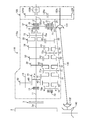
図1は、本発明の実施形態1に係る手動変速機10を示す。この手動変速機10は、車両(本実施形態では、FR車)の前部に搭載されていて、エンジン2(駆動源)に結合されてエンジン2と共にパワーユニットを構成している。本実施形態では、手動変速機10の最高変速段は6速である。
(Embodiment 1)
FIG. 1 shows a
手動変速機10は、変速機ケース10aと、入力側動力伝達軸11と、この入力側動力伝達軸11と同一軸線上に配置された出力側動力伝達軸12と、入力側動力伝達軸11(及び出力側動力伝達軸12)と平行に配置されたカウンタ軸21と、入力側動力伝達軸11及びカウンタ軸21と平行に配置されたリバース軸13と、を備えている。入力側動力伝達軸11、出力側動力伝達軸12、カウンタ軸21及びリバース軸13は、変速機ケース10a内に収容されていて、前記車両の前後方向に延びている。カウンタ軸21は、入力側動力伝達軸11及び出力側動力伝達軸12の下側に位置する。リバース軸13は、図1では便宜上、入力側動力伝達軸11の上側に記載しているが、実際には、入力側動力伝達軸11と出力側動力伝達軸12との間の高さ位置であって両動力伝達軸11,12の側方に位置する。
The
入力側動力伝達軸11は、手動変速機10の入力部を構成する。入力側動力伝達軸11の一端部(車両前側の端部(図1の左側端部))は、前記車両の乗員(ドライバ)の踏み込み操作により切断状態とされるクラッチ3を介して、エンジン2の出力軸2a(クランク軸)に連結されている。これにより、エンジン2の動力が入力側動力伝達軸11に入力される。
The input side
出力側動力伝達軸12は、手動変速機10の出力部を構成する。出力側動力伝達軸12は、入力側動力伝達軸11に対して反エンジン2側(車両後側)に配置されている。出力側動力伝達軸12の車両前側の端部には、後述の5−6速用同期装置75を介して、入力側動力伝達軸11の車両後側の端部が係合する係合部12aが設けられている。この係合により、入力側動力伝達軸11と出力側動力伝達軸12とが係合(直結)されることになる。出力側動力伝達軸12の車両後側の端部は、駆動輪(本実施形態では、後輪)に、プロペラシャフト、デファレンシャル機構等を介して連結される。
The output side power transmission shaft 12 constitutes an output part of the
本実施形態では、最高変速段(6速)時のみにおいて、入力側動力伝達軸11と出力側動力伝達軸12とが直結された状態になる。すなわち、手動変速機10は、6速直結タイプの手動変速機であり、6速は直結変速段となる。
In the present embodiment, the input-side
入力側動力伝達軸11は、そのエンジン2側の端部近傍(後述のリバース用ドライブギヤ40のエンジン2側)に配置された軸受14を介して、変速機ケース10aに回転可能に支持されている。入力側動力伝達軸11の車両後側の端部は、出力側動力伝達軸12の車両前側の端部に回転可能に支持されている。また、出力側動力伝達軸12は、後述のドリブンギヤ47に対して出力側動力伝達軸12の軸方向両側に配置された2つの軸受15,16を介して、変速機ケース10aに回転自在に支持されている。さらに、カウンタ軸21は、そのエンジン2側の端部に配置された軸受22と、後述のドライブギヤ57に対してカウンタ軸21の軸方向両側に配置された2つの軸受23,24とを介して、変速機ケース10aに回転自在に支持されている。また、リバース軸13は、変速機ケース10aに固設されている。
The input side
入力側動力伝達軸11とカウンタ軸21との間には、複数の前進変速段用ギヤ列が設けられている。これら複数の前進変速段用ギヤ列は、1速から最高変速段の1段低速側の変速段(本実施形態では、5速)までの各変速段用ギヤ列であって、入力側動力伝達軸11の軸方向に並んでいる。本実施形態では、前記複数の前進変速段用ギヤ列は、1速用ギヤ列31、2速用ギヤ列32、3速用ギヤ列33、4速用ギヤ列34、及び5速用ギヤ列35であって、エンジン2側からこの順に配置されている。これにより、これら複数(5つ)の前進変速段用ギヤ列は、入力側動力伝達軸11の軸方向においてエンジン2側ほど低速の変速段用ギヤ列(エンジン2側ほど減速比が大きい変速段用ギヤ列)となるように配置されていることになる。
Between the input side
尚、手動変速機10は、前記の如く6速直結タイプの手動変速機であるため、最高変速段用ギヤ列(6速用ギヤ列)は設けられていない。
Since the
前記5つの前進変速段用ギヤ列は、各々、入力側動力伝達軸11上及びカウンタ軸21上にそれぞれ配置されかつ互いに噛合う一組のギヤを有する。
Each of the five forward gear stages has a set of gears that are respectively disposed on the input side
具体的に、1速用ギヤ列31は、入力側動力伝達軸11上に配置された1速用ドライブギヤ41と、カウンタ軸21上に配置され、1速用ドライブギヤ41と噛合う1速用ドリブンギヤ51とを有する。1速用ドライブギヤ41は、入力側動力伝達軸11に固定されていて、入力側動力伝達軸11と一体的に回転する。1速用ドリブンギヤ51は、カウンタ軸21に対して回転自在に遊嵌合されている。
Specifically, the first-
2速用ギヤ列32は、入力側動力伝達軸11上に配置された2速用ドライブギヤ42と、カウンタ軸21上に配置され、2速用ドライブギヤ42と噛合う2速用ドリブンギヤ52とを有する。2速用ドライブギヤ42は、入力側動力伝達軸11に固定されていて、入力側動力伝達軸11と一体的に回転する。2速用ドリブンギヤ52は、カウンタ軸21に対して回転自在に遊嵌合されている。
The second-
3速用ギヤ列33は、入力側動力伝達軸11上に配置された3速用ドライブギヤ43と、カウンタ軸21上に配置され、3速用ドライブギヤ43と噛合う3速用ドリブンギヤ53とを有する。3速用ドライブギヤ43は、入力側動力伝達軸11に固定されていて、入力側動力伝達軸11と一体的に回転する。3速用ドリブンギヤ53は、カウンタ軸21に対して回転自在に遊嵌合されている。
The 3-
4速用ギヤ列34は、入力側動力伝達軸11上に配置された4速用ドライブギヤ44と、カウンタ軸21上に配置され、4速用ドライブギヤ44と噛合う4速用ドリブンギヤ54とを有する。4速用ドライブギヤ44は、入力側動力伝達軸11に固定されていて、入力側動力伝達軸11と一体的に回転する。4速用ドリブンギヤ54は、カウンタ軸21に対して回転自在に遊嵌合されている。
The 4-
5速用ギヤ列35は、入力側動力伝達軸11上に配置された5速用ドライブギヤ45と、カウンタ軸21上に配置され、5速用ドライブギヤ45と噛合う5速用ドリブンギヤ55とを有する。5速用ドライブギヤ45は、入力側動力伝達軸11に対して回転自在に遊嵌合され、5速用ドリブンギヤ55は、入力側動力伝達軸11に固定されている。
The 5-
入力側動力伝達軸11とカウンタ軸21とリバース軸13との間には、リバース用ギヤ列30が設けられている。このリバース用ギヤ列30は、入力側動力伝達軸11上、カウンタ軸21上及びリバース軸13上にそれぞれ配置されかつ互いに噛合う一組のギヤを有する。具体的に、リバース用ギヤ列30は、入力側動力伝達軸11上に配置されたリバース用ドライブギヤ40と、カウンタ軸21上に配置されたリバース用ドリブンギヤ50と、リバース軸13上に配置され、リバース用ドライブギヤ40及びリバース用ドリブンギヤ50と噛合うリバース用アイドルギヤ60とを有する。
A
リバース用ギヤ列30は、入力側動力伝達軸11の軸方向において、全ての前記前進変速段用ギヤ列(1速用ギヤ列31、2速用ギヤ列32、3速用ギヤ列33、4速用ギヤ列34、及び5速用ギヤ列35)よりもエンジン2側に配置されている。すなわち、リバース用ギヤ列30は、前記5つの前進変速段用ギヤ列のうち最もエンジン2側に位置する1速用ギヤ列31よりもエンジン2側に配置されている。言い換えれば、前記5つの前進変速段用ギヤ列のうち、減速比が最も大きい1速用ギヤ列31が、リバース用ギヤ列30に対して、入力側動力伝達軸11の軸方向の反エンジン2側に隣接配置されている。
The
本実施形態では、リバース用ドライブギヤ40の歯面及び1速用ドライブギヤ41の歯面が、入力側動力伝達軸11の軸方向に互いに連続して形成されている。すなわち、リバース用ドライブギヤ40のハブが、1速用ドライブギヤ41のハブ41aと共用され、このハブ41aに対して入力側動力伝達軸11の軸方向のエンジン2側にリバース用ドライブギヤ40の歯面が設けられ、エンジン2とは反対側に1速用ドライブギヤ41の歯面が設けられている。リバース用ドライブギヤ40の歯面は、1速用ドライブギヤ41の歯面に対してエンジン2側に連続して延設されて形成されたものであり、リバース用ドライブギヤ40と1速用ドライブギヤ41との歯面形状及び歯数は同じである。1速用ドライブギヤ41は、リバース用ドライブギヤ40を兼用しているとも言える。リバース用ドライブギヤ40も、1速用ドライブギヤ41と同様に、入力側動力伝達軸11に固定されていて、入力側動力伝達軸11と一体的に回転することになる。リバース用ドリブンギヤ50は、カウンタ軸21に対して回転自在に遊嵌合されている。リバース用アイドルギヤ60は、リバース軸13に回転可能に支持されている。
In the present embodiment, the tooth surface of the
また、カウンタ軸21と出力側動力伝達軸12との間には、カウンタ軸21の回転を減速して出力側動力伝達軸12に出力する減速ギヤ列37が設けられている。すなわち、手動変速機10は、アウトプットリダクションタイプの手動変速機である。減速ギヤ列37は、カウンタ軸21上及び出力側動力伝達軸12上にそれぞれ配置されかつ互いに噛合う一組のギヤを有する。具体的に、減速ギヤ列37は、カウンタ軸21上に配置されたドライブギヤ57と、出力側動力伝達軸12上に配置され、ドライブギヤ57と噛み合うドリブンギヤ47とを有する。ドライブギヤ57は、カウンタ軸21における5速用ドリブンギヤ55よりも反エンジン2側(カウンタ軸21における車両後側の端部近傍)に固定されていて、カウンタ軸21と一体的に回転する。ドリブンギヤ47は、出力側動力伝達軸12に固定されていて、出力側動力伝達軸12と一体的に回転する。ドライブギヤ57の径は、ドリブンギヤ47の径よりも小さいとともに、5速用ドライブギヤ45の径よりも小さい。
A
カウンタ軸21上におけるリバース用ドリブンギヤ50のエンジン2側には、リバース用ドリブンギヤ50とカウンタ軸21との間を断接するためのリバース用同期装置70が配設されている。このリバース用同期装置70は、カウンタ軸21上において前記軸受14と入力側動力伝達軸11の軸方向にオーバーラップする位置に配設されている。リバース用同期装置70は、カウンタ軸21の軸方向にスライド可能なスリーブ70aを有している。前記車両の乗員によるチェンジレバーのリバースシフト操作により、スリーブ70aが中立位置から反エンジン2側にスライドし、このスライドにより、リバース用ドリブンギヤ50がカウンタ軸21に連結固定される。この結果、エンジン2の動力が、クラッチ3、入力側動力伝達軸11、リバース用ドライブギヤ40、リバース用アイドルギヤ60、リバース用ドリブンギヤ50を介して、カウンタ軸22に伝達され、このカウンタ軸22に伝達された動力が、減速ギヤ列37のドライブギヤ57及びドリブンギヤ47を介して、出力側動力伝達軸12に伝達される。こうして、後退速が達成される。
A
また、カウンタ軸21上における1速用ドリブンギヤ51と2速用ドリブンギヤ52との間には、1速用ドリブンギヤ51とカウンタ軸21との間、及び、2速用ドリブンギヤ52とカウンタ軸21との間を断接するための1−2速用同期装置71が配設されている。1−2速用同期装置71は、カウンタ軸21の軸方向にスライド可能なスリーブ71aを有している。
Further, between the first-speed driven
前記乗員によるチェンジレバーの1速へのシフト操作により、スリーブ71aが中立位置からエンジン2側にスライドし、このスライドにより、1速用ドリブンギヤ51がカウンタ軸21に連結固定される。この結果、エンジン2の動力が、クラッチ3、入力側動力伝達軸11、1速用ドライブギヤ41及び1速用ドリブンギヤ51を介して、カウンタ軸22に伝達され、このカウンタ軸22に伝達された動力が、減速ギヤ列37のドライブギヤ57及びドリブンギヤ47を介して、出力側動力伝達軸12に伝達される。こうして、1速が達成される。出力側動力伝達軸12に伝達された動力は、プロペラシャフト、デファレンシャル機構等を介して、後輪に伝達される。
When the occupant shifts the change lever to the first speed, the
前記乗員によるチェンジレバーの2速へのシフト操作により、スリーブ71aが前記中立位置から反エンジン2側にスライドし、このスライドにより、2速用ドリブンギヤ52がカウンタ軸21に連結固定される。この結果、エンジン2の動力が、クラッチ3、入力側動力伝達軸11、2速用ドライブギヤ42及び2速用ドリブンギヤ52を介して、カウンタ軸22に伝達され、このカウンタ軸22に伝達された動力が、減速ギヤ列37のドライブギヤ57及びドリブンギヤ47を介して、出力側動力伝達軸12に伝達される。こうして、2速が達成される。
When the occupant shifts the change lever to the second speed, the
さらに、カウンタ軸21上における3速用ドリブンギヤ53と4速用ドリブンギヤ53との間には、3速用ドリブンギヤ53とカウンタ軸21との間、及び、4速用ドリブンギヤ53とカウンタ軸21との間を断接するための3−4速用同期装置73が配設されている。3−4速用同期装置73は、カウンタ軸21の軸方向にスライド可能なスリーブ73aを有している。
Further, between the third-speed driven
前記乗員によるチェンジレバーの3速へのシフト操作により、スリーブ73aが中立位置からエンジン2側にスライドし、このスライドにより、3速用ドリブンギヤ53がカウンタ軸21に連結固定される。この結果、エンジン2の動力が、クラッチ3、入力側動力伝達軸11、3速用ドライブギヤ43及び3速用ドリブンギヤ53を介して、カウンタ軸22に伝達され、このカウンタ軸22に伝達された動力が、減速ギヤ列37のドライブギヤ57及びドリブンギヤ47を介して、出力側動力伝達軸12に伝達される。こうして、3速が達成される。
When the occupant shifts the change lever to the third speed, the
前記乗員によるチェンジレバーの4速へのシフト操作により、スリーブ73aが前記中立位置から反エンジン2側にスライドし、このスライドにより、4速用ドリブンギヤ54がカウンタ軸21に連結固定される。この結果、エンジン2の動力が、クラッチ3、入力側動力伝達軸11、4速用ドライブギヤ44及び4速用ドリブンギヤ54を介して、カウンタ軸22に伝達され、このカウンタ軸22に伝達された動力が、減速ギヤ列37のドライブギヤ57及びドリブンギヤ47を介して、出力側動力伝達軸12に伝達される。こうして、4速が達成される。
When the occupant shifts the change lever to the fourth speed, the
また、入力側動力伝達軸11における5速用ドライブギヤ45の反エンジン2側(入力側動力伝達軸11における車両後側の端部近傍)には、5速用ドライブギヤ45と入力側動力伝達軸11との間、及び、入力側動力伝達軸11と出力側動力伝達軸12との間を断接するための5−6速用同期装置75が配設されている。5−6速用同期装置75は、入力側動力伝達軸11の軸方向にスライド可能なスリーブ75aを有している。
Further, the fifth-
前記乗員によるチェンジレバーの5速へのシフト操作により、スリーブ75aが中立位置からエンジン2側にスライドし、このスライドにより、5速用ドライブギヤ45が入力側動力伝達軸11に連結固定される。この結果、エンジン2の動力が、クラッチ3、入力側動力伝達軸11、5速用ドライブギヤ45及び5速用ドリブンギヤ55を介して、カウンタ軸22に伝達され、このカウンタ軸22に伝達された動力が、減速ギヤ列37のドライブギヤ57及びドリブンギヤ47を介して、出力側動力伝達軸12に伝達される。こうして、5速が達成される。
The
前記乗員によるチェンジレバーの6速へのシフト操作により、スリーブ75aが前記中立位置から反エンジン2側にスライドし、このスライドにより、5−6速用同期装置75を介して入力側動力伝達軸11が出力側動力伝達軸12の係合部12aに係合される。すなわち、入力側動力伝達軸11と出力側動力伝達軸12とが直結される。この結果、エンジン2の動力が、クラッチ3及び入力側動力伝達軸11を介して、出力側動力伝達軸12に伝達される。このように、最高変速段である6速(直結変速段)が、入力側動力伝達軸11と出力側動力伝達軸12とを係合(直結)させることにより実現される。
When the occupant shifts the change lever to the sixth speed, the
前記5つの前進変速段用ギヤ列(1速用ギヤ列31、2速用ギヤ列32、3速用ギヤ列33、4速用ギヤ列34、及び5速用ギヤ列35)、リバース用ギヤ列30、減速ギヤ列37、前記同期装置70,71,73,75、軸受14〜16、並びに軸受22〜24も、入力側動力伝達軸11、出力側動力伝達軸12、カウンタ軸21及びリバース軸13と共に、変速機ケース10a内に収容されている。
The five forward gear trains (
前記5つの前進変速段用ギヤ列は、前記したように、エンジン2側ほど低速の変速段用ギヤ列となるように配置されているので、前記5つの前進変速段用ギヤ列におけるカウンタ軸21上のギヤ(1速用ドリブンギヤ51、2速用ドリブンギヤ52、3速用ドリブンギヤ53、4速用ドリブンギヤ54及び5速用ドリブンギヤ55)の径は、反エンジン2側ほど小さくなる。また、減速ギヤ列37のドライブギヤ57の径は、5速用ドリブンギヤ55の径よりも小さい。さらに、リバース用ギヤ列30のリバース用ドリブンギヤ50の径は、1速用ドリブンギヤ51の径と略同じである(厳密には、1速用ドリブンギヤ51の径よりも少し小さい)。
As described above, the five forward shift gear trains are arranged so as to become a lower gear train as the engine 2 side becomes lower. Therefore, the
変速機ケース10aは、入力側動力伝達軸11の軸方向においてリバース用ギヤ列30が存在する部分で、リバース用アイドルギヤ60があるために、入力側動力伝達軸11の径方向に最も大きくなる。本実施形態では、変速機ケース10aは、エンジン2側の端部で入力側動力伝達軸11の径方向に最も大きくなる。そして、5つの前進変速段用ギヤ列及び減速ギヤ列37における、カウンタ軸21上に配置されているギヤの径が、反エンジン2側ほど小さくなることに対応して、変速機ケース10aは、反エンジン2側(車両後側)に行くにしたがって、入力側動力伝達軸11の径方向に小さくなる。特に変速機ケース10aの下側部分が、反エンジン2側に行くにしたがって上側に位置する。
The
(実施形態2)
図2は、本発明の実施形態2に係る手動変速機110を示す。尚、図1と同じ部分については同じ符号を付して、その詳細な説明は省略する(後に図3により説明する実施形態3についても同様)。
(Embodiment 2)
FIG. 2 shows a
本実施形態では、手動変速機110が搭載される車両は、FR車をベースとする四輪駆動車である。手動変速機110は、この車両の前部に搭載されていて、エンジン2に結合されてエンジン2と共にパワーユニットを構成している。本実施形態においても、手動変速機110の最高変速段は6速であり、6速は直結変速段である。
In the present embodiment, the vehicle on which the
手動変速機110の出力側動力伝達軸12は、出力側動力伝達軸12のトルク(前記パワーユニットの出力トルク)を、後輪に加えて前輪にも分配するために、トランスファ装置120の動力伝達軸120aに連結されている。
The output side power transmission shaft 12 of the
トランスファ装置120は、前記動力伝達軸120aと、後輪及び前輪へ伝達されるトルク比を50:50から100:0までの範囲で変更可能な伝達トルク可変クラッチ120bと、前輪へトルクを出力するための前輪側出力軸120cと、動力伝達軸120aと前輪側出力軸120cとの間に設けられ、動力伝達軸120aのトルクの一部を前輪側出力軸120cに伝達するギヤ列120dとを備えている。
The
ギヤ列120dは、動力伝達軸120a上に伝達トルク可変クラッチ120bを介して配置されたドライブギヤ120eと、前輪側出力軸120c上に配置され、ドライブギヤ120eと噛み合うドリブンギヤ120fとを有する。ドリブンギヤ120fは前輪側出力軸120cに固定されていて、前輪側出力軸120cと一体的に回転する。前輪側出力軸120cは、変速機ケース110aの下側に配設されたフロントプロペラシャフト130と、該フロントプロペラシャフト130の両端に配設された等速ジョイント131,132とを介して、フロントデファレンシャルギヤ140の入力軸と連結されている。動力伝達軸120aの車両後側の端部は、後輪に、リヤプロペラシャフト、リヤデファレンシャル機構等を介して連結される。尚、ギヤ列120dのドライブギヤ120e及びドリブンギヤ120fを共にスプロケットに代えて、該両スプロケットにチェーンを架け渡すようにして、該チェーンを介して、動力伝達軸120aのトルクの一部を前輪側出力軸120cに伝達するようにしてもよい。
The
自動変速機110の構成は、前記実施形態1の自動変速機10と同様であり、自動変速機110の変速機ケース110aの大きさについても、自動変速機10の変速機ケース10aと同様である。フロントプロペラシャフト130は、変速機ケース110aの下側部分の形状に沿うように傾斜して配置されている。すなわち、フロントプロペラシャフト130は、車両後側に向かって上昇するように傾斜している。これにより、車両後側の等速ジョイント131の方が、車両前側の等速ジョイント132よりも高い高さ位置に位置している。
The configuration of the
以上のように前記実施形態1及び2によれば、リバースギヤ列30が、入力側動力伝達軸11の軸方向において、全ての前記前進変速段用ギヤ列(1速用ギヤ列31、2速用ギヤ列32、3速用ギヤ列33、4速用ギヤ列34、及び5速用ギヤ列35)よりもエンジン2側に配置されているので、リバース用ギヤ列30が前記5つの前進変速段用ギヤ列間に配置されることはなく、変速機ケース10a,110a内に、前記5つの前進変速段用ギヤ列とリバースギヤ列30とを分けて配置することができる。これにより、変速機ケース10a,110aは、入力側動力伝達軸11の軸方向の中間部分で、入力側動力伝達軸11の径方向に部分的に大型化するようなことはなく、よって、手動変速機10,110の車両への搭載性が悪化するのを抑制することができる。
As described above, according to the first and second embodiments, the
また、リバース用ギヤ列30の前記配置により、変速機ケース10a,110aのエンジン2側の端部の近傍が、入力側動力伝達軸11の径方向に大きくなるが、該端部は、エンジン2と強固に結合するために、入力側動力伝達軸11の径方向に大きくされる傾向にあり、この点からは、変速機ケース10a,110aのエンジン2側の端部が入力側動力伝達軸11の径方向に大きくなる方が都合がよい。また、エンジン2と結合する部分の近傍で、変速機ケース10a,110aが入力側動力伝達軸11の径方向に大きくなっても、手動変速機10,110の車両への搭載性が悪化するようなことはない。
Further, due to the arrangement of the
さらに、前記実施形態1及び2によれば、前記5つの前進変速段用ギヤ列のうち減速比が最も大きい1速用ギヤ列31が、リバースギヤ列30に対して、入力側動力伝達軸11の軸方向の反エンジン2側に隣接配置されるので、変速機ケース10a,110a内において、カウンタ軸21上で径が最も大きな1速用ドリブンギヤ51に対して、入力側動力伝達軸11の軸方向のエンジン2側に隣接するスペースに、1速用ドリブンギヤ51と同等の大きさのリバース用ドリブンギヤ50を容易に配置することができる。
Further, according to the first and second embodiments, the first-
また、前記実施形態1及び2によれば、リバース用ドライブギヤ40の歯面及び1速用ドライブギヤ41の歯面が、入力側動力伝達軸11の軸方向に互いに連続して形成されているので、これらリバース用ドライブギヤ40及び1速用ドライブギヤ41の特に歯面の製造性を向上させることができ、これら両ギヤ40,41の製造コストを低減することができる。
Further, according to the first and second embodiments, the tooth surface of the
さらにまた、前記実施形態1及び2によれば、前記5つの前進変速段用ギヤ列(1速用ギヤ列31、2速用ギヤ列32、3速用ギヤ列33、4速用ギヤ列34、及び5速用ギヤ列35)が、エンジン2側ほど低速の変速段用ギヤ列(エンジン2側ほど減速比が大きい変速段用ギヤ列)となるように配置されているので、前記5つの前進変速段用ギヤ列におけるカウンタ軸21上のギヤ(1速用ドリブンギヤ51、2速用ドリブンギヤ52、3速用ドリブンギヤ53、4速用ドリブンギヤ54及び5速用ドリブンギヤ55)の径は、反エンジン2側ほど小さくなる。これにより、手動変速機10,110におけるカウンタ軸21の周辺(特に手動変速機10,110の下側)に配置される周辺部品と変速機ケース10,110との干渉を抑制して手動変速機10,110をスペース効率良く配置することができる。前記周辺部品は、例えばエンジン2の排気系部品である、触媒を含む排気浄化装置である。特に四輪駆動車では、フロントプロペラシャフト130のスペースが必要になるが、前記実施形態2で説明したように、手動変速機110の下側にフロントプロペラシャフト130を傾斜させて配置することで、手動変速機110、フロントプロペラシャフト130、排気浄化装置等をスペース効率良く配置することができる。
Furthermore, according to the first and second embodiments, the five forward gear trains (
さらに、前記実施形態1及び2によれば、カウンタ軸21上におけるリバース用ドリブンギヤ50のエンジン2側に、リバース用同期装置70が配設され、このリバース用同期装置70が、カウンタ軸21上において、入力側動力伝達軸11を支持する軸受14(リバース用ドライブギヤ40のエンジン2側に配設されている)と入力側動力伝達軸11の軸方向にオーバーラップする位置に配設されているので、カウンタ軸21上における、軸受14と入力側動力伝達軸11の軸方向にオーバーラップするスペースを有効に活用することができ、この結果、手動変速機10,110の全体を、入力側動力伝達軸11の軸方向に短縮することができる。
Further, according to the first and second embodiments, the
(実施形態3)
図3は、本発明の実施形態3に係る手動変速機210を示す。この手動変速機210が搭載される車両は、前記実施形態1の手動変速機10と同様に、FR車である。
(Embodiment 3)
FIG. 3 shows a manual transmission 210 according to Embodiment 3 of the present invention. The vehicle on which the manual transmission 210 is mounted is an FR vehicle, like the
本実施形態では、3−4速用同期装置73が、入力側動力伝達軸11上に配置されている。これに関連して、3速用ギヤ列33の3速用ドライブギヤ43及び4速用ギヤ列34の4速用ドライブギヤ44が、入力側動力伝達軸11に対して回転自在に遊嵌合され、3速用ドリブンギヤ53及び4速用ドリブンギヤ54が、カウンタ軸21に固定されている。3−4速用同期装置73は、3速用ドライブ43と入力側動力伝達軸11との間、及び、4速用ドライブギヤ44と入力側動力伝達軸11との間を断接することになる。
In the present embodiment, the 3-4
前記車両の乗員によるチェンジレバーの3速へのシフト操作により、3−4速用同期装置73のスリーブ73aが中立位置からエンジン2側にスライドし、このスライドにより、3速用ドライブギヤ43が入力側動力伝達軸11に連結固定される。また、前記乗員によるチェンジレバーの4速へのシフト操作により、スリーブ73aが前記中立位置から反エンジン2側にスライドし、このスライドにより、4速用ドライブギヤ44が入力側動力伝達軸11に連結固定される。
As the vehicle occupant shifts the change lever to the 3rd speed, the
このように本実施形態では、前記5つの前進変速段用ギヤ列のうち2速よりも高速の変速段用ギヤ列(つまり、3速用ギヤ列33、4速用ギヤ列34及び5速用ギヤ列35)が、入力側動力伝達軸11上に遊嵌合された状態で配置されたドライブギヤ(3速用ドライブギヤ43、4速用ドライブギヤ44及び5速用ドライブギヤ45)と、カウンタ軸21上に該カウンタ軸21と一体的に回転するように配置されたドリブンギヤ(3速用ドリブンギヤ53、4速用ドリブンギヤ54及び5速用ドリブンギヤ55)とを有する。
As described above, in the present embodiment, among the five forward shift gear trains, the gear train for the speed gear higher than the second gear (that is, the
そして、前記2速よりも高速の変速段用ギヤ列の前記ドライブギヤと入力側動力伝達軸11との間を断接するための同期装置(3−4速用同期装置73及び5−6速用同期装置75)が、入力側動力伝達軸11上に配設されている。
Then, a synchronizer for connecting / disconnecting the drive gear and the input side
手動変速機210におけるその他の構成は、前記実施形態1の自動変速機10と同様であり、自動変速機210の変速機ケース210aの大きさについても、自動変速機10の変速機ケース10aと同様である。
Other configurations of the manual transmission 210 are the same as those of the
尚、手動変速機210の構成を、前記実施形態2の自動変速機110に適用することも可能である。
Note that the configuration of the manual transmission 210 can be applied to the
本実施形態によれば、前記実施形態1及び2と同様の作用効果が得られることに加えて、カウンタ軸21に3−4速用同期装置73が配設されていないので、前記実施形態1及び2に比べて、直結変速段時(6速時)に減速ギヤ列37を介して空転するカウンタ軸21全体のイナーシャを低減することができる。この結果、直結変速段時に、特に減速ギヤ列37のドライブギヤ57とドリブンギヤ47との間で生じるギヤノイズを低減することができる。
According to this embodiment, in addition to the same effects as those of the first and second embodiments, the
本発明は、前記実施形態に限られるものではなく、請求の範囲の主旨を逸脱しない範囲で代用が可能である。 The present invention is not limited to the above-described embodiment, and can be substituted without departing from the scope of the claims.
例えば、前記実施形態では、最高変速段が6速でありかつ6速直結タイプの手動変速機に本発明を適用した場合について説明したが、最高変速段が、入力側動力伝達軸と出力側動力伝達軸とを係合させることで実現されるように構成された手動変速機であれば、最高変速段が6速の手動変速機に限られるものではない。最高変速段は、例えば4速又は5速であってもよいが、本発明の作用効果をより効果的に発揮させる観点からは、6速以上であることが好ましい。例えば最高変速段が8速でありかつ8速直結タイプの手動変速機に対して、本発明を好適に適用することができる。 For example, in the above-described embodiment, the case where the present invention is applied to a 6-speed direct connection type manual transmission having the maximum gear position of 6 speeds has been described. However, the maximum gear position includes the input-side power transmission shaft and the output-side power. As long as the manual transmission is configured to be realized by engaging the transmission shaft, the manual transmission is not limited to a manual transmission having a maximum gear of 6 speeds. The maximum gear position may be, for example, 4th speed or 5th speed, but is preferably 6th speed or more from the viewpoint of more effectively exerting the effects of the present invention. For example, the present invention can be suitably applied to a manual transmission having a maximum gear stage of 8 speeds and an 8-speed direct connection type.
また、前記実施形態では、複数の前進変速段用ギヤ列が、エンジン2側ほど低速の変速段用ギヤ列となるように配置されているが、複数の前進変速段用ギヤ列の、入力側動力伝達軸11の軸方向の並び順は、どのような順序であってもよい。また、1速用ギヤ列31が、リバース用ギヤ列30に対して、入力側動力伝達軸11の軸方向に隣接配置されていなくてもよい。但し、エンジン2側に、低速の変速段用ギヤ列を配置するのが好ましい。
Further, in the above-described embodiment, the plurality of forward shift gear trains are arranged so as to become the lower gear train for the lower speed as the engine 2 side. The order of arrangement of the
上述の実施形態は単なる例示に過ぎず、本発明の範囲を限定的に解釈してはならない。本発明の範囲は請求の範囲によって定義され、請求の範囲の均等範囲に属する変形や変更は、全て本発明の範囲内のものである。 The above-described embodiments are merely examples, and the scope of the present invention should not be interpreted in a limited manner. The scope of the present invention is defined by the scope of the claims, and all modifications and changes belonging to the equivalent scope of the claims are within the scope of the present invention.
本発明は、入力側動力伝達軸と出力側動力伝達軸とを係合(直結)させることで最高変速段を実現するアウトプットリダクションタイプの手動変速機に有用である。 INDUSTRIAL APPLICABILITY The present invention is useful for an output reduction type manual transmission that realizes the maximum gear position by engaging (directly connecting) an input side power transmission shaft and an output side power transmission shaft.
2 エンジン(駆動源)
10、110、210 手動変速機
10a、110a、210a 変速機ケース
11 入力側動力伝達軸
12 出力側動力伝達軸
13 リバース軸
14 リバース用ドライブギヤのエンジン側に配置された軸受
21 カウンタ軸
30 リバース用ギヤ列
31 1速用ギヤ列(前進変速段用ギヤ列)
32 2速用ギヤ列(前進変速段用ギヤ列)
33 3速用ギヤ列(前進変速段用ギヤ列)
34 4速用ギヤ列(前進変速段用ギヤ列)
35 5速用ギヤ列(前進変速段用ギヤ列)
37 減速ギヤ列
40 リバース用ドライブギヤ
41 1速用ドライブギヤ
42 2速用ドライブギヤ
43 3速用ドライブギヤ
44 4速用ドライブギヤ
45 5速用ドライブギヤ
50 リバース用ドリブンギヤ
51 1速用ドリブンギヤ
52 2速用ドリブンギヤ
53 3速用ドリブンギヤ
54 4速用ドリブンギヤ
55 5速用ドリブンギヤ
60 リバース用アイドルギヤ
70 リバース用同期装置
71 1−2速用同期装置
73 3−4速用同期装置
75 5−6速用同期装置
2 Engine (drive source)
10, 110, 210
32 Gear train for 2nd gear (gear train for forward speed)
33 3rd speed gear train (forward shift gear train)
34 4th speed gear train (forward gear train)
35 5-speed gear train (forward gear train)
37
Claims (7)
一端部が駆動源に連結され、該駆動源の動力が入力される入力側動力伝達軸と、
前記入力側動力伝達軸と平行に配置されたカウンタ軸と、
前記入力側動力伝達軸及び前記カウンタ軸と平行に配置されたリバース軸と、
前記入力側動力伝達軸と同一軸線上に配置された出力側動力伝達軸と、
前記入力側動力伝達軸上及び前記カウンタ軸上にそれぞれ配置されかつ互いに噛合う一組のギヤを各々有する複数の前進変速段用ギヤ列と、
前記入力側動力伝達軸上、前記カウンタ軸上及び前記リバース軸上にそれぞれ配置されかつ互いに噛合う一組のギヤを有するリバース用ギヤ列と、
前記カウンタ軸上及び前記出力側動力伝達軸上にそれぞれ配置されかつ互いに噛合う一組のギヤを有するとともに、前記カウンタ軸の回転を減速して前記出力側動力伝達軸に出力する減速ギヤ列と、
を備え、
最高変速段が、前記入力側動力伝達軸と前記出力側動力伝達軸とを係合させることにより実現されるように構成された手動変速機であって、
前記リバース用ギヤ列は、前記入力側動力伝達軸の軸方向において、全ての前記前進変速段用ギヤ列よりも前記駆動源側に配置されていることを特徴する手動変速機。 In the transmission case,
An input side power transmission shaft having one end connected to a drive source and input of power from the drive source;
A counter shaft arranged in parallel with the input side power transmission shaft;
A reverse shaft arranged in parallel with the input side power transmission shaft and the counter shaft;
An output-side power transmission shaft disposed on the same axis as the input-side power transmission shaft;
A plurality of forward gear stages each having a pair of gears arranged on the input side power transmission shaft and the counter shaft and meshing with each other;
A reverse gear train having a set of gears arranged on the input side power transmission shaft, on the counter shaft and on the reverse shaft and meshing with each other;
A reduction gear train having a pair of gears disposed on the counter shaft and the output side power transmission shaft and meshing with each other, and decelerating the rotation of the counter shaft and outputting it to the output side power transmission shaft; ,
With
A manual transmission configured to achieve a maximum gear position by engaging the input-side power transmission shaft and the output-side power transmission shaft;
The manual transmission, wherein the reverse gear train is disposed closer to the drive source than all the forward gear trains in the axial direction of the input-side power transmission shaft.
前記複数の前進変速段用ギヤ列のうちの1速用ギヤ列が、前記リバース用ギヤ列に対して、入力側動力伝達軸の軸方向に隣接配置されていることを特徴とする手動変速機。 The manual transmission according to claim 1, wherein
A manual transmission in which a first-speed gear train among the plurality of forward gear trains is disposed adjacent to the reverse gear train in the axial direction of the input-side power transmission shaft. .
前記リバース用ギヤ列は、前記入力側動力伝達軸上に配置されたリバース用ドライブギヤと、前記カウンタ軸上に配置されたリバース用ドリブンギヤと、前記リバース軸上に配置され、前記リバース用ドライブギヤ及び前記リバース用ドリブンギヤと噛合うリバース用アイドルギヤと、を有し、
前記1速用ギヤ列は、前記入力側動力伝達軸上に配置された1速用ドライブギヤと、前記カウンタ軸上に配置され、該1速用ドライブギヤと噛合う1速用ドリブンギヤと、を有し、
前記リバース用ドライブギヤの歯面及び前記1速用ドライブギヤの歯面が、前記入力側動力伝達軸の軸方向に互いに連続して形成されていることを特徴とする手動変速機。 The manual transmission according to claim 2, wherein
The reverse gear train includes a reverse drive gear disposed on the input-side power transmission shaft, a reverse driven gear disposed on the counter shaft, and a reverse drive gear disposed on the reverse shaft. And a reverse idle gear meshing with the reverse driven gear,
The first-speed gear train includes: a first-speed drive gear disposed on the input-side power transmission shaft; and a first-speed driven gear disposed on the counter shaft and meshing with the first-speed drive gear. Have
A manual transmission, wherein a tooth surface of the reverse drive gear and a tooth surface of the first-speed drive gear are formed continuously in the axial direction of the input-side power transmission shaft.
前記リバース用ドライブギヤの前記駆動源側に、前記入力側動力伝達軸を変速機ケースに支持するための軸受が配置され、
前記リバース用ドリブンギヤは、前記カウンタ軸上に遊嵌合された状態で配置されており、
前記カウンタ軸上における前記リバース用ドリブンギヤの前記駆動源側であって、前記軸受と前記入力側動力伝達軸の軸方向にオーバーラップする位置には、前記リバース用ドリブンギヤと前記カウンタ軸との間を断接するためのリバース用同期装置が配設されていることを特徴とする手動変速機。 The manual transmission according to claim 3, wherein
A bearing for supporting the input-side power transmission shaft on a transmission case is disposed on the drive source side of the reverse drive gear,
The reverse driven gear is arranged in a loosely fitted state on the counter shaft,
On the counter shaft, on the drive source side of the reverse driven gear, at a position overlapping the bearing and the input side power transmission shaft in the axial direction, there is a gap between the reverse driven gear and the counter shaft. A manual transmission comprising a reverse synchronization device for connecting and disconnecting.
前記複数の前進変速段用ギヤ列のうち2速よりも高速の変速段用ギヤ列が、前記入力側動力伝達軸上に遊嵌合された状態で配置されたドライブギヤと、前記カウンタ軸上に該カウンタ軸と一体的に回転するように配置されたドリブンギヤと、を有し、
前記2速よりも高速の変速段用ギヤ列の前記ドライブギヤと前記入力側動力伝達軸との間を断接するための同期装置が、前記入力側動力伝達軸上に配設されていることを特徴とする手動変速機。 The manual transmission according to any one of claims 2 to 4,
A drive gear arranged in a state in which a gear stage for a speed higher than the second speed is loosely fitted on the input-side power transmission shaft among the plurality of forward gear stages; And a driven gear arranged to rotate integrally with the counter shaft,
A synchronizer for connecting and disconnecting the drive gear and the input-side power transmission shaft of the gear train for gears higher than the second speed is disposed on the input-side power transmission shaft; Features a manual transmission.
前記複数の前進変速段用ギヤ列は、前記入力側動力伝達軸の軸方向において前記駆動源側ほど低速の変速段用ギヤ列となるように配置されていることを特徴とする手動変速機。 The manual transmission according to any one of claims 1 to 5,
The manual transmission according to claim 1, wherein the plurality of forward shift gear trains are arranged so as to become gear trains for lower speed gears closer to the drive source side in the axial direction of the input-side power transmission shaft.
前記最高変速段は、6速以上であることを特徴とする手動変速機。 The manual transmission according to any one of claims 1 to 6,
The manual transmission is characterized in that the maximum gear stage is 6 speeds or more.
Priority Applications (1)
| Application Number | Priority Date | Filing Date | Title |
|---|---|---|---|
| DE102016008086.8A DE102016008086B4 (en) | 2015-07-06 | 2016-07-01 | manual transmission |
Applications Claiming Priority (2)
| Application Number | Priority Date | Filing Date | Title |
|---|---|---|---|
| JP2015135481 | 2015-07-06 | ||
| JP2015135481 | 2015-07-06 |
Publications (2)
| Publication Number | Publication Date |
|---|---|
| JP2017015250A true JP2017015250A (en) | 2017-01-19 |
| JP6512175B2 JP6512175B2 (en) | 2019-05-15 |
Family
ID=57830189
Family Applications (1)
| Application Number | Title | Priority Date | Filing Date |
|---|---|---|---|
| JP2016104407A Expired - Fee Related JP6512175B2 (en) | 2015-07-06 | 2016-05-25 | Manual transmission |
Country Status (1)
| Country | Link |
|---|---|
| JP (1) | JP6512175B2 (en) |
Cited By (1)
| Publication number | Priority date | Publication date | Assignee | Title |
|---|---|---|---|---|
| EP3575638A1 (en) | 2018-06-01 | 2019-12-04 | Mazda Motor Corporation | Transmission of vehicle and manufacturing method thereof |
Citations (7)
| Publication number | Priority date | Publication date | Assignee | Title |
|---|---|---|---|---|
| JPH09236177A (en) * | 1996-02-29 | 1997-09-09 | Suzuki Motor Corp | Gear transmission |
| WO1999000612A1 (en) * | 1997-06-27 | 1999-01-07 | Zf Friedrichshafen Ag | Gearbox with direct gear and overdrive gear versions |
| JP2003515713A (en) * | 1999-12-02 | 2003-05-07 | ツェットエフ、フリードリッヒスハーフェン、アクチエンゲゼルシャフト | transmission |
| JP2004197888A (en) * | 2002-12-20 | 2004-07-15 | Isuzu Motors Ltd | Transmission |
| JP2005026578A (en) * | 2003-07-04 | 2005-01-27 | Nikon Corp | Photoelectric detecting device |
| JP2009287614A (en) * | 2008-05-27 | 2009-12-10 | Isuzu Motors Ltd | Synchronizing device for parallel shaft gear mechanism type transmission |
| JP2014092220A (en) * | 2012-11-02 | 2014-05-19 | Isuzu Motors Ltd | Gear structure of transmission |
-
2016
- 2016-05-25 JP JP2016104407A patent/JP6512175B2/en not_active Expired - Fee Related
Patent Citations (7)
| Publication number | Priority date | Publication date | Assignee | Title |
|---|---|---|---|---|
| JPH09236177A (en) * | 1996-02-29 | 1997-09-09 | Suzuki Motor Corp | Gear transmission |
| WO1999000612A1 (en) * | 1997-06-27 | 1999-01-07 | Zf Friedrichshafen Ag | Gearbox with direct gear and overdrive gear versions |
| JP2003515713A (en) * | 1999-12-02 | 2003-05-07 | ツェットエフ、フリードリッヒスハーフェン、アクチエンゲゼルシャフト | transmission |
| JP2004197888A (en) * | 2002-12-20 | 2004-07-15 | Isuzu Motors Ltd | Transmission |
| JP2005026578A (en) * | 2003-07-04 | 2005-01-27 | Nikon Corp | Photoelectric detecting device |
| JP2009287614A (en) * | 2008-05-27 | 2009-12-10 | Isuzu Motors Ltd | Synchronizing device for parallel shaft gear mechanism type transmission |
| JP2014092220A (en) * | 2012-11-02 | 2014-05-19 | Isuzu Motors Ltd | Gear structure of transmission |
Cited By (1)
| Publication number | Priority date | Publication date | Assignee | Title |
|---|---|---|---|---|
| EP3575638A1 (en) | 2018-06-01 | 2019-12-04 | Mazda Motor Corporation | Transmission of vehicle and manufacturing method thereof |
Also Published As
| Publication number | Publication date |
|---|---|
| JP6512175B2 (en) | 2019-05-15 |
Similar Documents
| Publication | Publication Date | Title |
|---|---|---|
| JP4793777B2 (en) | Double clutch transmission | |
| JP5312242B2 (en) | transmission | |
| KR102451883B1 (en) | Power transmission apparatus for vehicle | |
| JP6137809B2 (en) | Dual clutch automatic transmission | |
| JP2008298223A (en) | Transmission | |
| JP5277069B2 (en) | transmission | |
| JP7209401B2 (en) | power transmission device | |
| JP2007292227A (en) | Planetary gear train of multi-stage transmission | |
| JP5195679B2 (en) | Automatic transmission for vehicles | |
| JP2009210020A (en) | Transmission | |
| JP2013019424A (en) | Transmission for vehicle | |
| JP4877196B2 (en) | transmission | |
| JP5276272B2 (en) | Industrial vehicle transmission | |
| JP6421682B2 (en) | Automatic transmission | |
| JP5329477B2 (en) | transmission | |
| JP2008291892A (en) | Twin-clutch type transmission | |
| JP2008075721A (en) | Automatic transmission | |
| JP2017015250A (en) | Manual transmission | |
| WO2018163949A1 (en) | Hybrid vehicle transmission | |
| JP2010151303A (en) | Transmission | |
| JP2009121591A (en) | Multi-stage shift planetary gear train | |
| KR20170110495A (en) | Transmission for hybrid vehicle | |
| JP2008291893A (en) | Dual clutch type transmission | |
| JP2008298260A (en) | Transmission | |
| WO2013008544A1 (en) | Transmission |
Legal Events
| Date | Code | Title | Description |
|---|---|---|---|
| A621 | Written request for application examination |
Free format text: JAPANESE INTERMEDIATE CODE: A621 Effective date: 20170323 |
|
| A977 | Report on retrieval |
Free format text: JAPANESE INTERMEDIATE CODE: A971007 Effective date: 20171213 |
|
| A131 | Notification of reasons for refusal |
Free format text: JAPANESE INTERMEDIATE CODE: A131 Effective date: 20180109 |
|
| A521 | Request for written amendment filed |
Free format text: JAPANESE INTERMEDIATE CODE: A523 Effective date: 20180312 |
|
| A131 | Notification of reasons for refusal |
Free format text: JAPANESE INTERMEDIATE CODE: A131 Effective date: 20180828 |
|
| A521 | Request for written amendment filed |
Free format text: JAPANESE INTERMEDIATE CODE: A523 Effective date: 20181024 |
|
| TRDD | Decision of grant or rejection written | ||
| A01 | Written decision to grant a patent or to grant a registration (utility model) |
Free format text: JAPANESE INTERMEDIATE CODE: A01 Effective date: 20190312 |
|
| A61 | First payment of annual fees (during grant procedure) |
Free format text: JAPANESE INTERMEDIATE CODE: A61 Effective date: 20190325 |
|
| R150 | Certificate of patent or registration of utility model |
Ref document number: 6512175 Country of ref document: JP Free format text: JAPANESE INTERMEDIATE CODE: R150 |
|
| LAPS | Cancellation because of no payment of annual fees |