JP2017011132A - Wire winding method and wire winding apparatus - Google Patents
Wire winding method and wire winding apparatus Download PDFInfo
- Publication number
- JP2017011132A JP2017011132A JP2015125928A JP2015125928A JP2017011132A JP 2017011132 A JP2017011132 A JP 2017011132A JP 2015125928 A JP2015125928 A JP 2015125928A JP 2015125928 A JP2015125928 A JP 2015125928A JP 2017011132 A JP2017011132 A JP 2017011132A
- Authority
- JP
- Japan
- Prior art keywords
- core
- nozzle
- wires
- wire
- around
- Prior art date
- Legal status (The legal status is an assumption and is not a legal conclusion. Google has not performed a legal analysis and makes no representation as to the accuracy of the status listed.)
- Granted
Links
- 238000004804 winding Methods 0.000 title claims abstract description 76
- 238000000034 method Methods 0.000 title claims abstract description 45
- 238000003780 insertion Methods 0.000 claims abstract description 20
- 230000037431 insertion Effects 0.000 claims abstract description 20
- 238000004519 manufacturing process Methods 0.000 claims description 4
- 238000000576 coating method Methods 0.000 description 7
- 239000011248 coating agent Substances 0.000 description 5
- 210000001015 abdomen Anatomy 0.000 description 4
- 238000006243 chemical reaction Methods 0.000 description 3
- 239000000463 material Substances 0.000 description 3
- 239000000696 magnetic material Substances 0.000 description 2
- 229910018605 Ni—Zn Inorganic materials 0.000 description 1
- PNEYBMLMFCGWSK-UHFFFAOYSA-N aluminium oxide Inorganic materials [O-2].[O-2].[O-2].[Al+3].[Al+3] PNEYBMLMFCGWSK-UHFFFAOYSA-N 0.000 description 1
- 230000006866 deterioration Effects 0.000 description 1
- 239000012212 insulator Substances 0.000 description 1
- 239000011347 resin Substances 0.000 description 1
- 229920005989 resin Polymers 0.000 description 1
- 230000037303 wrinkles Effects 0.000 description 1
- 229910000859 α-Fe Inorganic materials 0.000 description 1
Images


Classifications
-
- H—ELECTRICITY
- H01—ELECTRIC ELEMENTS
- H01F—MAGNETS; INDUCTANCES; TRANSFORMERS; SELECTION OF MATERIALS FOR THEIR MAGNETIC PROPERTIES
- H01F41/00—Apparatus or processes specially adapted for manufacturing or assembling magnets, inductances or transformers; Apparatus or processes specially adapted for manufacturing materials characterised by their magnetic properties
- H01F41/02—Apparatus or processes specially adapted for manufacturing or assembling magnets, inductances or transformers; Apparatus or processes specially adapted for manufacturing materials characterised by their magnetic properties for manufacturing cores, coils, or magnets
- H01F41/04—Apparatus or processes specially adapted for manufacturing or assembling magnets, inductances or transformers; Apparatus or processes specially adapted for manufacturing materials characterised by their magnetic properties for manufacturing cores, coils, or magnets for manufacturing coils
- H01F41/06—Coil winding
- H01F41/082—Devices for guiding or positioning the winding material on the former
-
- B—PERFORMING OPERATIONS; TRANSPORTING
- B65—CONVEYING; PACKING; STORING; HANDLING THIN OR FILAMENTARY MATERIAL
- B65H—HANDLING THIN OR FILAMENTARY MATERIAL, e.g. SHEETS, WEBS, CABLES
- B65H54/00—Winding, coiling, or depositing filamentary material
- B65H54/02—Winding and traversing material on to reels, bobbins, tubes, or like package cores or formers
- B65H54/026—Doubling winders, i.e. for winding two or more parallel yarns on a bobbin, e.g. in preparation for twisting or weaving
-
- H—ELECTRICITY
- H01—ELECTRIC ELEMENTS
- H01F—MAGNETS; INDUCTANCES; TRANSFORMERS; SELECTION OF MATERIALS FOR THEIR MAGNETIC PROPERTIES
- H01F41/00—Apparatus or processes specially adapted for manufacturing or assembling magnets, inductances or transformers; Apparatus or processes specially adapted for manufacturing materials characterised by their magnetic properties
- H01F41/02—Apparatus or processes specially adapted for manufacturing or assembling magnets, inductances or transformers; Apparatus or processes specially adapted for manufacturing materials characterised by their magnetic properties for manufacturing cores, coils, or magnets
- H01F41/04—Apparatus or processes specially adapted for manufacturing or assembling magnets, inductances or transformers; Apparatus or processes specially adapted for manufacturing materials characterised by their magnetic properties for manufacturing cores, coils, or magnets for manufacturing coils
- H01F41/06—Coil winding
- H01F41/064—Winding non-flat conductive wires, e.g. rods, cables or cords
- H01F41/069—Winding two or more wires, e.g. bifilar winding
-
- B—PERFORMING OPERATIONS; TRANSPORTING
- B65—CONVEYING; PACKING; STORING; HANDLING THIN OR FILAMENTARY MATERIAL
- B65H—HANDLING THIN OR FILAMENTARY MATERIAL, e.g. SHEETS, WEBS, CABLES
- B65H2701/00—Handled material; Storage means
- B65H2701/30—Handled filamentary material
- B65H2701/36—Wires
-
- H—ELECTRICITY
- H01—ELECTRIC ELEMENTS
- H01F—MAGNETS; INDUCTANCES; TRANSFORMERS; SELECTION OF MATERIALS FOR THEIR MAGNETIC PROPERTIES
- H01F17/00—Fixed inductances of the signal type
- H01F17/04—Fixed inductances of the signal type with magnetic core
- H01F17/045—Fixed inductances of the signal type with magnetic core with core of cylindric geometry and coil wound along its longitudinal axis, i.e. rod or drum core
-
- H—ELECTRICITY
- H01—ELECTRIC ELEMENTS
- H01F—MAGNETS; INDUCTANCES; TRANSFORMERS; SELECTION OF MATERIALS FOR THEIR MAGNETIC PROPERTIES
- H01F17/00—Fixed inductances of the signal type
- H01F2017/0093—Common mode choke coil
-
- H—ELECTRICITY
- H01—ELECTRIC ELEMENTS
- H01F—MAGNETS; INDUCTANCES; TRANSFORMERS; SELECTION OF MATERIALS FOR THEIR MAGNETIC PROPERTIES
- H01F41/00—Apparatus or processes specially adapted for manufacturing or assembling magnets, inductances or transformers; Apparatus or processes specially adapted for manufacturing materials characterised by their magnetic properties
- H01F41/02—Apparatus or processes specially adapted for manufacturing or assembling magnets, inductances or transformers; Apparatus or processes specially adapted for manufacturing materials characterised by their magnetic properties for manufacturing cores, coils, or magnets
- H01F41/04—Apparatus or processes specially adapted for manufacturing or assembling magnets, inductances or transformers; Apparatus or processes specially adapted for manufacturing materials characterised by their magnetic properties for manufacturing cores, coils, or magnets for manufacturing coils
- H01F41/06—Coil winding
- H01F41/064—Winding non-flat conductive wires, e.g. rods, cables or cords
- H01F41/069—Winding two or more wires, e.g. bifilar winding
- H01F41/07—Twisting
Landscapes
- Engineering & Computer Science (AREA)
- Power Engineering (AREA)
- Manufacturing & Machinery (AREA)
- Textile Engineering (AREA)
- Coil Winding Methods And Apparatuses (AREA)
Abstract
Description
本発明は、ワイヤ巻回方法およびワイヤ巻回装置に関する。 The present invention relates to a wire winding method and a wire winding apparatus.
従来、コイル部品のコアに複数のワイヤを巻き回すワイヤ巻回方法としては、特開2010−147132号公報(特許文献1)に記載されたものがある。このワイヤ巻回方法は、2本のワイヤをガイドとノズルとに順に通して、2本のワイヤの先端をコアに接続する第1工程と、ノズルを所定回数だけ正方向に自転させて、ガイドとノズルの間およびノズルとコイルの間にワイヤの撚り部を形成する第2工程と、コアを回転させて、ノズルとコイルの間のワイヤの撚り部をコアに巻き回す第3工程と、ノズルを逆方向に自転させて、ガイドとノズルの間のワイヤの撚り部の撚りを戻す第4工程とを有する。 Conventionally, as a wire winding method for winding a plurality of wires around a core of a coil component, there is one described in JP 2010-147132 A (Patent Document 1). In this wire winding method, a first step of passing two wires through a guide and a nozzle in order and connecting the tips of the two wires to the core, and rotating the nozzle in the forward direction a predetermined number of times, the guide A second step of forming a twisted portion of the wire between the nozzle and between the nozzle and the coil, a third step of rotating the core and winding the twisted portion of the wire between the nozzle and the coil around the core, and the nozzle And a fourth step of returning the twist of the twisted portion of the wire between the guide and the nozzle.
ところで、前記従来のワイヤ巻回方法を実際に使用すると、次の問題があることを発見した。ガイドとノズルの間の2本のワイヤを一度撚りその撚りを戻す際に、ガイドとノズルの間の2本のワイヤにおいて、ねじれ癖がついたり、ワイヤの被膜がこすれて損傷するおそれがある。 By the way, when the conventional wire winding method is actually used, it has been found that there is the following problem. When the two wires between the guide and the nozzle are once twisted and then untwisted, the two wires between the guide and the nozzle may be twisted or damaged by rubbing the coating of the wire.
そこで、本発明の課題は、ワイヤのねじれ癖や損傷を防止したワイヤ巻回方法およびワイヤ巻回装置を提供することにある。 Then, the subject of this invention is providing the wire winding method and the wire winding apparatus which prevented the twisted wrinkle and damage of the wire.
前記課題を解決するため、本発明のワイヤ巻回方法は、
コイル部品のコアに複数のワイヤを巻き回すワイヤ巻回方法であって、
前記複数のワイヤをテンショナとノズルとに順に通して、前記複数のワイヤの先端をコア側に固定する第1工程と、
前記複数のワイヤのそれぞれが通されたノズルの複数のワイヤ挿通孔の相互の位置関係が前記テンショナに対して一定となるように、前記ノズルを前記コアの周囲に公転させて、前記複数のワイヤをねじりながら前記コアに巻き付ける第2工程と
を備える。
In order to solve the above-mentioned problem, the wire winding method of the present invention includes:
A wire winding method for winding a plurality of wires around a core of a coil component,
A first step of sequentially passing the plurality of wires through a tensioner and a nozzle, and fixing tips of the plurality of wires to the core side;
The nozzles are revolved around the core so that the mutual positional relationship of the plurality of wire insertion holes of the nozzle through which each of the plurality of wires passes is constant with respect to the tensioner, and the plurality of wires And a second step of winding the core around the core while twisting.
本発明のワイヤ巻回方法によれば、複数のワイヤのそれぞれが通されたノズルの複数のワイヤ挿通孔の相互の位置関係がテンショナに対して一定となるように、ノズルをコアの周囲に公転させて、複数のワイヤをねじりながらコアに巻き付ける。 According to the wire winding method of the present invention, the nozzle is revolved around the core so that the mutual positional relationship between the plurality of wire insertion holes of the nozzle through which each of the plurality of wires passes is constant with respect to the tensioner. And winding a plurality of wires around the core while twisting them.
したがって、テンショナとノズルの間の複数のワイヤをねじらずに、ノズルとコアの間の複数のワイヤのみをねじることができる。このように、テンショナとノズルの間の複数のワイヤをねじらないので、テンショナとノズルの間の複数のワイヤにおいて、ねじれ癖がつかず、かつ、ワイヤの被膜がこすれて損傷しない。 Therefore, only the plurality of wires between the nozzle and the core can be twisted without twisting the plurality of wires between the tensioner and the nozzle. In this way, since the plurality of wires between the tensioner and the nozzle are not twisted, the wires between the tensioner and the nozzle are not twisted and the coating of the wire is rubbed and not damaged.
また、ワイヤ巻回方法の一実施形態では、前記第2工程では、前記ノズルを前記コアの周囲に公転させながら、前記コアを前記ノズルの回転方向と同じ方向に自転させる。 In an embodiment of the wire winding method, in the second step, the core is rotated in the same direction as the rotation direction of the nozzle while revolving the nozzle around the core.
前記実施形態によれば、ノズルをコアの周囲に公転させながら、コアをノズルの回転方向と同じ方向に自転させるので、複数のワイヤの単位ターン数あたりのねじりピッチを容易に変更できる。 According to the embodiment, since the core is rotated in the same direction as the rotation direction of the nozzle while the nozzle is revolved around the core, the twist pitch per unit turn of the plurality of wires can be easily changed.
また、ワイヤ巻回方法の一実施形態では、前記ノズルの回転数は、前記コアの回転数よりも大きい。 In one embodiment of a wire winding method, the number of rotations of the nozzle is larger than the number of rotations of the core.
前記実施形態によれば、ノズルの回転数は、コアの回転数よりも大きいので、複数のワイヤの単位ターン数あたりのねじりピッチを増加できる。これにより、モード変換特性の改善が見込める。 According to the embodiment, since the number of rotations of the nozzle is larger than the number of rotations of the core, the twist pitch per unit number of turns of the plurality of wires can be increased. Thereby, the improvement of the mode conversion characteristic can be expected.
また、ワイヤ巻回方法の一実施形態では、前記第2工程では、前記ノズルを前記コアの周囲に公転させながら、前記コアを前記ノズルの回転方向と反対方向に自転させる。 In one embodiment of the wire winding method, in the second step, the core is rotated in the direction opposite to the rotation direction of the nozzle while the nozzle is revolved around the core.
前記実施形態によれば、ノズルをコアの周囲に公転させながら、コアをノズルの回転方向と反対方向に自転させるので、複数のワイヤをコアに迅速に巻き回すことができる。 According to the embodiment, since the core is rotated in the direction opposite to the rotation direction of the nozzle while revolving the nozzle around the core, a plurality of wires can be quickly wound around the core.
また、コイル部品の製造方法では、前記ワイヤ巻回方法によって前記コアに前記ワイヤを巻き付けて、前記コイル部品を製造する。 In the coil component manufacturing method, the coil component is manufactured by winding the wire around the core by the wire winding method.
前記実施形態によれば、ワイヤ巻回方法によってコアにワイヤを巻き付けて、コイル部品を製造するので、ワイヤのねじれ癖や損傷を防止したコイル部品を製造することができる。 According to the embodiment, since the coil component is manufactured by winding the wire around the core by the wire winding method, it is possible to manufacture the coil component that prevents the wire from being twisted and damaged.
本発明のワイヤ巻回装置は、
コイル部品のコアに複数のワイヤを巻き回すワイヤ巻回装置であって、
前記複数のワイヤに張力を加えるためのテンショナと、
前記テンショナによって張力を加えられる前記複数のワイヤのそれぞれが通される複数のワイヤ挿通孔を有するノズルと、
前記ノズルの前記複数のワイヤ挿通孔の相互の位置関係が前記テンショナに対して一定となるように、前記ノズルを前記コアの周囲に公転させて、前記複数のワイヤをねじりながら前記コアに巻き付けるノズル駆動部と
を備える。
The wire winding device of the present invention comprises:
A wire winding device for winding a plurality of wires around a core of a coil component,
A tensioner for applying tension to the plurality of wires;
A nozzle having a plurality of wire insertion holes through which each of the plurality of wires to which tension is applied by the tensioner;
The nozzle that revolves around the core and winds the plurality of wires around the core while twisting the plurality of wires so that the mutual positional relationship of the plurality of wire insertion holes of the nozzle is constant with respect to the tensioner A drive unit.
本発明のワイヤ巻回装置によれば、ノズルは、テンショナによって張力を加えられる複数のワイヤのそれぞれが通される複数のワイヤ挿通孔を有する。ノズル駆動部は、ノズルの複数のワイヤ挿通孔の相互の位置関係がテンショナに対して一定となるように、ノズルをコアの周囲に公転させて、複数のワイヤをねじりながらコアに巻き付ける。 According to the wire winding device of the present invention, the nozzle has a plurality of wire insertion holes through which each of the plurality of wires to which tension is applied by the tensioner is passed. The nozzle drive unit revolves the nozzle around the core so that the mutual positional relationship between the plurality of wire insertion holes of the nozzle is constant with respect to the tensioner, and winds the plurality of wires around the core while twisting.
したがって、テンショナとノズルの間の複数のワイヤをねじらずに、ノズルとコアの間の複数のワイヤのみをねじることができる。このように、テンショナとノズルの間の複数のワイヤをねじらないので、テンショナとノズルの間の複数のワイヤにおいて、ねじれ癖がつかず、かつ、ワイヤの被膜がこすれて損傷しない。 Therefore, only the plurality of wires between the nozzle and the core can be twisted without twisting the plurality of wires between the tensioner and the nozzle. In this way, since the plurality of wires between the tensioner and the nozzle are not twisted, the wires between the tensioner and the nozzle are not twisted and the coating of the wire is rubbed and not damaged.
また、ワイヤ巻回方法の一実施形態では、前記ノズルの回転方向と同じ方向に前記コアを自転させるコア駆動部を有する。 Moreover, in one Embodiment of a wire winding method, it has a core drive part which autorotates the said core in the same direction as the rotation direction of the said nozzle.
前記実施形態によれば、コア駆動部は、ノズルの回転方向と同じ方向にコアを自転させる。したがって、ノズルをコアの周囲に公転させながら、コアをノズルの回転方向と同じ方向に自転させることができ、複数のワイヤの単位ターン数あたりのねじりピッチを容易に変更できる。 According to the embodiment, the core driving unit rotates the core in the same direction as the rotation direction of the nozzle. Therefore, the core can be rotated in the same direction as the rotation direction of the nozzle while the nozzle is revolved around the core, and the twist pitch per unit turn of the plurality of wires can be easily changed.
また、ワイヤ巻回方法の一実施形態では、前記コア駆動部は、前記ノズルの回転数を前記コアの回転数よりも大きくする。 Moreover, in one Embodiment of a wire winding method, the said core drive part makes the rotation speed of the said nozzle larger than the rotation speed of the said core.
前記実施形態によれば、コア駆動部は、ノズルの回転数をコアの回転数よりも大きくするので、複数のワイヤの単位ターン数あたりのねじりピッチを増加できる。これにより、モード変換特性の改善が見込める。 According to the embodiment, since the core driving unit makes the number of rotations of the nozzle larger than the number of rotations of the core, the twist pitch per unit turn number of the plurality of wires can be increased. Thereby, the improvement of the mode conversion characteristic can be expected.
また、ワイヤ巻回方法の一実施形態では、前記ノズルの回転方向と反対方向に前記コアを自転させるコア駆動部を有する。 Moreover, in one Embodiment of a wire winding method, it has a core drive part which autorotates the said core in the direction opposite to the rotation direction of the said nozzle.
前記実施形態によれば、コア駆動部は、ノズルの回転方向と反対方向にコアを自転させる。したがって、ノズルをコアの周囲に公転させながら、コアをノズルの回転方向と反対方向に自転させることができ、複数のワイヤをコアに迅速に巻き回すことができる。 According to the embodiment, the core driving unit rotates the core in the direction opposite to the rotation direction of the nozzle. Therefore, the core can be rotated in the direction opposite to the rotation direction of the nozzle while the nozzle revolves around the core, and a plurality of wires can be quickly wound around the core.
本発明のワイヤ巻回方法およびワイヤ巻回装置によれば、テンショナとノズルの間の複数のワイヤをねじらないので、テンショナとノズルの間の複数のワイヤにおいて、ねじれ癖がつかず、かつ、ワイヤの被膜がこすれて損傷しない。 According to the wire winding method and the wire winding apparatus of the present invention, since the plurality of wires between the tensioner and the nozzle are not twisted, the plurality of wires between the tensioner and the nozzle are not twisted, and The wire coating is rubbed and not damaged.
以下、本発明を図示の実施の形態により詳細に説明する。 Hereinafter, the present invention will be described in detail with reference to the illustrated embodiments.
(第1実施形態)
図1は、本発明のワイヤ巻回方法の第1実施形態を示す説明図である。図1に示すように、ワイヤ巻回方法は、コイル部品のコア10に第1、第2ワイヤ21,22を巻き回す方法である。第1、第2ワイヤ21,22をコア10に巻き回して、コイル部品が製造される。コイル部品は、例えば、コモンモードチョークコイルである。
(First embodiment)
FIG. 1 is an explanatory view showing a first embodiment of the wire winding method of the present invention. As shown in FIG. 1, the wire winding method is a method of winding the first and
コア10は、巻芯部13と、巻芯部13の一端に設けられた第1鍔部11と、巻芯部13の他端に設けられた第2鍔部12とを有する。コア10の材料としては、例えば、アルミナ(非磁性体)や、Ni−Zn系フェライト(磁性体、絶縁体)や、樹脂などの材料を用いる。
The
巻芯部13の形状は、例えば、直方体である。第1鍔部11の形状と第2鍔部12の形状は、例えば、矩形の平板である。第1鍔部11の底面および第2鍔部12の底面には、それぞれ、第1電極31および第2電極32が設けられている。第1、第2電極31,32の材料は、例えば、Ag等である。第1、第2電極31,32は、図示しない実装基板の電極に電気的に接続される。
The shape of the
第1、第2ワイヤ21,22は、導線と導線を覆う被膜とを有する。第1ワイヤ21は、コア10に巻き回されることで、一次側コイルを構成する。第2ワイヤ22は、コア10に巻き回されることで、二次側コイルを構成する。
The first and
次に、ワイヤ巻回方法について説明する。 Next, the wire winding method will be described.
まず、第1、第2ワイヤ21,22を第1、第2テンショナ51,52とノズル60とに順に通して、第1、第2ワイヤ21,22の先端をコア10側に固定する。以下、この工程を第1工程という。
First, the first and
第1工程において、第1、第2ワイヤ21,22は、図示しないコイルボビンから引き出される。第1テンショナ51は、第1ワイヤ21に張力を加える。第2テンショナ52は、第2ワイヤ22に張力を加える。
In the first step, the first and
ノズル60は、第1、第2ワイヤ挿通孔61,62を有する。第1ワイヤ挿通孔61には、第1テンショナ51によって張力を加えられる第1ワイヤ21が通される。第2ワイヤ挿通孔62には、第2テンショナ52によって張力を加えられる第2ワイヤ22が通される。
The
第1ワイヤ21の先端は、コア10の第1鍔部11の第1電極31に接続される。第2ワイヤ22の先端は、コア10の第1鍔部11の第2電極32に接続される。そして、第1、第2ワイヤ21,22は、第1、第2テンショナ51,52とコア10との間で、第1、第2テンショナ51,52により、張力を加えられる。コア10は、第1鍔部11と第2鍔部12を結ぶ長軸L方向がZ方向に一致するように、XY面上に設置される。
The distal end of the
第1工程の後に、図2の平面図に示すように、ノズル60の第1、第2ワイヤ挿通孔61,62の相互の位置関係が第1、第2テンショナ51,52に対して一定となるように、ノズル60をコア10の周囲に公転させて、第1、第2ワイヤ21,22をねじりながらコア10に巻き付ける。以下、この工程を第2工程という。
After the first step, as shown in the plan view of FIG. 2, the mutual positional relationship between the first and second wire insertion holes 61 and 62 of the
第2工程において、ノズル60は、Z軸を中心として、コア10の周囲を公転する。このとき、第1、第2ワイヤ挿通孔61,62の左右の位置関係は、第1、第2テンショナ51,52に対して変わらない。
In the second step, the
このようにノズル60を公転させることで、図3に示すように、第1、第2テンショナ51,52とノズル60の間の第1、第2ワイヤ21,22をねじらずに、ノズル60とコア10の間の第1、第2ワイヤ21,22のみをねじることができる。また、ノズル60をZ方向に沿って第1鍔部11から第2鍔部12に向かって移動させることで、第1、第2ワイヤ21,22を第1鍔部11から第2鍔部12に向かって巻き付けることができる。
By revolving the
したがって、第1、第2テンショナ51,52とノズル60の間の第1、第2ワイヤ21,22をねじらないので、第1、第2テンショナ51,52とノズル60の間の第1、第2ワイヤ21,22において、ねじれ癖がつかず、かつ、第1、第2ワイヤ21,22の被膜がこすれて損傷しない。要するに、第1、第2ワイヤ21,22のコア10に巻き回す部分だけをねじることで、第1、第2ワイヤ21,22の損傷を防止して、短絡や断線のリスクを軽減し、信頼性低下や設備トラブルを抑制できる。
Accordingly, since the first and
また、第1、第2ワイヤ21,22をねじって巻芯部13に巻き回すことができ(ツイスト巻きとでき)、コイル特性を安定化できる。この実施形態では、巻芯部13のサイズによらず、第1、第2ワイヤ21,22を1ターンにつき2回クロスさせることができる。
Further, the first and
第2工程において、第1、第2ワイヤ21,22を巻芯部13に巻き回した後、図4に示すように、第1ワイヤ21の巻き終わりの端部を、コア10の第2鍔部12の第1電極31に接続し、第2ワイヤ22の巻き終わりの端部を、コア10の第2鍔部12の第2電極32に接続する。これにより、コイル部品1を製造する。したがって、前記ワイヤ巻回方法によってコア10にワイヤ21,22を巻き付けて、コイル部品1を製造するので、ワイヤ21,22のねじれ癖や損傷を防止したコイル部品1を製造することができる。
In the second step, after the first and
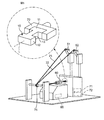
次に、ワイヤ巻回装置について説明する。 Next, the wire winding device will be described.
図5に示すように、ワイヤ巻回装置は、前記第1、前記第2テンショナ51,52と、前記ノズル60と、コア10を掴むチャック70と、ノズル60を駆動するノズル駆動部65とを有する。第1、第2テンショナ51,52およびノズル60は、前述で説明した通りである。第1、第2テンショナ51,52とノズル60との間には、プーリ75が配置され、第1、第2ワイヤ21,22を誘導する。
As shown in FIG. 5, the wire winding device includes the first and
チャック70は、コア10の第1鍔部11を掴んで固定する。このとき、コア10は、コア10の長軸L方向が、ノズル60側を向くように、設置される。
The
ノズル駆動部65は、ノズル60の第1、第2ワイヤ挿通孔61,62の相互の位置関係が第1、第2テンショナ51,52に対して一定となるように、ノズル60をコア10の周囲に公転させて、第1、第2ワイヤ21,22をねじりながらコア10に巻き付ける。つまり、ノズル駆動部65は、ノズル60を、コア10の長軸Lを中心として公転させ、かつ、コア10の長軸L方向に沿って移動させる。
The
ワイヤ巻回装置によれば、ノズル駆動部65により、ノズル60の第1、第2ワイヤ挿通孔61,62の相互の位置関係が第1、第2テンショナ51,52に対して一定となるように、ノズル60をコア10の周囲に公転させて、第1、第2ワイヤ21,22をねじりながらコア10に巻き付ける。
According to the wire winding device, the mutual positional relationship between the first and second wire insertion holes 61 and 62 of the
したがって、第1、第2テンショナ51,52とノズル60の間の第1、第2ワイヤ21,22をねじらずに、ノズル60とコア10の間の第1、第2ワイヤ21,22のみをねじることができる。このように、第1、第2テンショナ51,52とノズル60の間の第1、第2ワイヤ21,22をねじらないので、第1、第2テンショナ51,52とノズル60の間の第1、第2ワイヤ21,22において、ねじれ癖がつかず、かつ、第1、第2ワイヤ21,22の被膜がこすれて損傷しない。
Accordingly, without twisting the first and
(第2実施形態)
図6は、本発明のワイヤ巻回方法の第2実施形態を示す説明図である。第2実施形態は、第1実施形態とは、第2工程のみが相違する。この相違する部分のみを以下に説明する。
(Second Embodiment)
FIG. 6 is an explanatory view showing a second embodiment of the wire winding method of the present invention. The second embodiment is different from the first embodiment only in the second step. Only this difference will be described below.
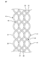
図6に示すように、第2実施形態の第2工程では、第1実施形態の第2工程に加え、さらに、ノズル60をコア10の周囲に公転させながら、コア10をノズル60の回転方向(矢印A方向)と同じ方向(矢印B方向)に自転させる。つまり、ノズル60をコア10の長軸Lを中心として公転させ、かつ、コア10をコア10の長軸Lを中心として自転させる。
As shown in FIG. 6, in the second step of the second embodiment, in addition to the second step of the first embodiment, the
したがって、ノズル60をコア10の周囲に公転させながら、コア10をノズル60の回転方向と同じ方向に自転させるので、第1、第2ワイヤ21,22の単位ターン数あたりのねじりピッチを容易に変更できる。例えば、図7に示すように、第1、第2ワイヤ21,22のねじりによって、腹部41および節部42が形成される。そして、隣り合うターンにおいて、一方のターンの腹部41と他方のターンの腹部41とを揃えることができる。このように、腹部41および節部42の位置を揃えることで、特性のバラつきを抑制できる。
Accordingly, the
また、ノズル60の回転数N1が、コア10の回転数N2よりも大きくてもよく、第1、第2ワイヤ21,22の単位ターン数あたりのねじりピッチを増加して、モード変換特性の改善が見込める。具体的に述べると、単位ターン数あたりのねじり量は、N1/N2となる。また、第1、第2ワイヤ21,22のコア10への巻回工程と、第1、第2ワイヤ21,22のねじれ工程とを、同時に行うことができる。
Further, the rotational speed N1 of the
なお、ノズル60の回転数N1が、コア10の回転数N2と同じであってもよく、このとき、第1、第2ワイヤ21,22は、コア10に巻き回されずに、ねじれるのみである。このため、第1、第2ワイヤ21,22のコア10への巻回工程と、第1、第2ワイヤ21,22のねじれ工程とを、別々に行うことができる。例えば、第1、第2ワイヤ21,22を先にねじってから、その後、ねじれた第1、第2ワイヤ21,22をコア10に巻き回すことができる。
The rotation speed N1 of the
次に、ワイヤ巻回装置の第2実施形態について説明する。 Next, a second embodiment of the wire winding device will be described.
ワイヤ巻回装置の第2実施形態は、図5を参照して、ワイヤ巻回装置の第1実施形態に加えて、さらに、コア10を駆動する第1コア駆動部71を有する。第1コア駆動部71は、ノズル60の回転方向と同じ方向にコア10を自転させる。これにより、ノズル60をコア10の周囲に公転させながら、コア10をノズル60の回転方向と同じ方向に自転させることができ、第1、第2ワイヤ21,22の単位ターン数あたりのねじりピッチを容易に変更できる。
Referring to FIG. 5, the second embodiment of the wire winding device further includes a first core driving unit 71 that drives the core 10 in addition to the first embodiment of the wire winding device. The first core driving unit 71 rotates the core 10 in the same direction as the rotation direction of the
また、第1コア駆動部71は、ノズル60の回転数をコア10の回転数よりも大きくしてもよく、第1、第2ワイヤ21,22の単位ターン数あたりのねじりピッチを増加できる。
In addition, the first core driving unit 71 may increase the rotational speed of the
(第3実施形態)
図8は、本発明のワイヤ巻回方法の第3実施形態を示す説明図である。第3実施形態は、第1実施形態とは、第2工程のみが相違する。この相違する部分のみを以下に説明する。
(Third embodiment)
FIG. 8 is an explanatory view showing a third embodiment of the wire winding method of the present invention. The third embodiment is different from the first embodiment only in the second step. Only this difference will be described below.
図8に示すように、第3実施形態の第2工程では、第1実施形態の第2工程に加え、さらに、ノズル60をコア10の周囲に公転させながら、コア10をノズル60の回転方向(矢印A方向)と反対方向(矢印C方向)に自転させる。つまり、ノズル60をコア10の長軸Lを中心として公転させ、かつ、コア10をコア10の長軸Lを中心として自転させる。
As shown in FIG. 8, in the second step of the third embodiment, in addition to the second step of the first embodiment, the
したがって、ノズル60をコア10の周囲に公転させながら、コア10をノズル60の回転方向と反対方向に自転させるので、第1、第2ワイヤ21,22をコア10に迅速に巻き回すことができる。
Accordingly, since the
また、ノズル60の回転数N1とコア10の回転数N2とを調整することで、単位ターン数あたりのねじり量を調整できる。具体的に述べると、単位ターン数あたりのねじり量は、1/(N1+N2)となる。
Moreover, the twist amount per unit turn number can be adjusted by adjusting the rotation speed N1 of the
次に、ワイヤ巻回装置の第3実施形態について説明する。 Next, a third embodiment of the wire winding device will be described.
ワイヤ巻回装置の第3実施形態は、図5を参照して、ワイヤ巻回装置の第1実施形態に加えて、さらに、コア10を駆動する第2コア駆動部72を有する。第2コア駆動部72は、ノズル60の回転方向と反対方向にコア10を自転させる。これにより、ノズル60をコア10の周囲に公転させながら、コア10をノズル60の回転方向と反対方向に自転させることができ、第1、第2ワイヤ21,22をコア10に迅速に巻き回すことができる。
With reference to FIG. 5, the third embodiment of the wire winding device further includes a second
なお、本発明は上述の実施形態に限定されず、本発明の要旨を逸脱しない範囲で設計変更可能である。例えば、第1から第3実施形態のそれぞれの特徴点を様々に組み合わせてもよい。 The present invention is not limited to the above-described embodiment, and the design can be changed without departing from the gist of the present invention. For example, the feature points of the first to third embodiments may be variously combined.
前記実施形態では、2本のワイヤをコアに巻き回しているが、3本以上のワイヤをコアに巻き回すようにしてもよい。このとき、ノズルは、3つ以上のワイヤ挿通孔を有する。 In the above embodiment, two wires are wound around the core, but three or more wires may be wound around the core. At this time, the nozzle has three or more wire insertion holes.
前記実施形態では、ワイヤの先端をコアの電極に接続してから、ノズルをコアの周囲に公転させているが、ワイヤの先端をコアに仮止めし又はコアを掴むチャックに固定してから、ノズルをコアの周囲に公転させ、その後、ワイヤの先端をコアの電極に接続するようにしてもよい。 In the above embodiment, the tip of the wire is connected to the electrode of the core, and then the nozzle is revolved around the core, but the tip of the wire is temporarily fixed to the core or fixed to the chuck that grips the core, The nozzle may be revolved around the core, and then the tip of the wire may be connected to the core electrode.
前記実施形態では、ノズルをコアの長軸方向に沿って移動させているが、コアをノズルに対してコアの長軸方向に沿って移動させるようにしてもよい。 In the above embodiment, the nozzle is moved along the long axis direction of the core. However, the core may be moved along the long axis direction of the core with respect to the nozzle.
前記実施形態では、第1、第2コア駆動部を別々に設けているが、第1、第2コア駆動部を両方設けて選択可能としてもよい。 In the embodiment, the first and second core driving units are provided separately, but both the first and second core driving units may be provided and selectable.
1 コイル部品
10 コア
11 第1鍔部
12 第2鍔部
13 巻芯部
21 第1ワイヤ
22 第2ワイヤ
31 第1電極
32 第2電極
51 第1テンショナ
52 第2テンショナ
60 ノズル
61 第1ワイヤ挿通孔
62 第2ワイヤ挿通孔
65 ノズル駆動部
70 チャック
71 第1コア駆動部
72 第2コア駆動部
L コアの長軸
DESCRIPTION OF
Claims (9)
前記複数のワイヤをテンショナとノズルとに順に通して、前記複数のワイヤの先端をコア側に固定する第1工程と、
前記複数のワイヤのそれぞれが通されたノズルの複数のワイヤ挿通孔の相互の位置関係が前記テンショナに対して一定となるように、前記ノズルを前記コアの周囲に公転させて、前記複数のワイヤをねじりながら前記コアに巻き付ける第2工程と
を備える、ワイヤ巻回方法。 A wire winding method for winding a plurality of wires around a core of a coil component,
A first step of passing the plurality of wires through a tensioner and a nozzle in order and fixing the tips of the plurality of wires to the core side;
The nozzles are revolved around the core so that the mutual positional relationship of the plurality of wire insertion holes of the nozzle through which each of the plurality of wires passes is constant with respect to the tensioner, and the plurality of wires And a second step of winding the wire around the core while twisting the wire.
前記複数のワイヤに張力を加えるためのテンショナと、
前記テンショナによって張力を加えられる前記複数のワイヤのそれぞれが通される複数のワイヤ挿通孔を有するノズルと、
前記ノズルの前記複数のワイヤ挿通孔の相互の位置関係が前記テンショナに対して一定となるように、前記ノズルを前記コアの周囲に公転させて、前記複数のワイヤをねじりながら前記コアに巻き付けるノズル駆動部と
を備える、ワイヤ巻回装置。 A wire winding device for winding a plurality of wires around a core of a coil component,
A tensioner for applying tension to the plurality of wires;
A nozzle having a plurality of wire insertion holes through which each of the plurality of wires to which tension is applied by the tensioner;
The nozzle that revolves around the core and winds the plurality of wires around the core while twisting the plurality of wires so that the mutual positional relationship of the plurality of wire insertion holes of the nozzle is constant with respect to the tensioner A wire winding device comprising a drive unit.
Priority Applications (4)
| Application Number | Priority Date | Filing Date | Title |
|---|---|---|---|
| JP2015125928A JP6269593B2 (en) | 2015-06-23 | 2015-06-23 | Wire winding method and wire winding apparatus |
| TW105116083A TWI609390B (en) | 2015-06-23 | 2016-05-24 | Wire winding method and wire winding apparatus |
| US15/184,707 US9842691B2 (en) | 2015-06-23 | 2016-06-16 | Wire winding method and wire winding apparatus |
| CN201610451954.3A CN106298228B (en) | 2015-06-23 | 2016-06-21 | Coil of wire winding method and coil of wire winding apparatus |
Applications Claiming Priority (1)
| Application Number | Priority Date | Filing Date | Title |
|---|---|---|---|
| JP2015125928A JP6269593B2 (en) | 2015-06-23 | 2015-06-23 | Wire winding method and wire winding apparatus |
Related Child Applications (1)
| Application Number | Title | Priority Date | Filing Date |
|---|---|---|---|
| JP2017248184A Division JP6409950B2 (en) | 2017-12-25 | 2017-12-25 | Wire winding method and wire winding apparatus |
Publications (2)
| Publication Number | Publication Date |
|---|---|
| JP2017011132A true JP2017011132A (en) | 2017-01-12 |
| JP6269593B2 JP6269593B2 (en) | 2018-01-31 |
Family
ID=57602784
Family Applications (1)
| Application Number | Title | Priority Date | Filing Date |
|---|---|---|---|
| JP2015125928A Active JP6269593B2 (en) | 2015-06-23 | 2015-06-23 | Wire winding method and wire winding apparatus |
Country Status (4)
| Country | Link |
|---|---|
| US (1) | US9842691B2 (en) |
| JP (1) | JP6269593B2 (en) |
| CN (1) | CN106298228B (en) |
| TW (1) | TWI609390B (en) |
Cited By (13)
| Publication number | Priority date | Publication date | Assignee | Title |
|---|---|---|---|---|
| JP2018195604A (en) * | 2017-05-12 | 2018-12-06 | 株式会社村田製作所 | Winding apparatus |
| JP2018195605A (en) * | 2017-05-12 | 2018-12-06 | 株式会社村田製作所 | Taping electronic component array |
| JP2018195603A (en) * | 2017-05-12 | 2018-12-06 | 株式会社村田製作所 | Winding apparatus and method of manufacturing coil component |
| JP2018195602A (en) * | 2017-05-12 | 2018-12-06 | 株式会社村田製作所 | Winding apparatus and method of manufacturing coil component |
| JP2019009255A (en) * | 2017-06-23 | 2019-01-17 | 株式会社村田製作所 | Manufacturing method of coil component and winding device |
| JP2019121693A (en) * | 2018-01-05 | 2019-07-22 | Tdk株式会社 | Common mode filter |
| JP2019153703A (en) * | 2018-03-03 | 2019-09-12 | 株式会社村田製作所 | Common mode choke coil |
| JP2019216145A (en) * | 2018-06-11 | 2019-12-19 | 株式会社村田製作所 | Coil component |
| JP2019216147A (en) * | 2018-06-11 | 2019-12-19 | 株式会社村田製作所 | Taping reel, method of manufacturing coil component, and electronic component |
| JP2020043230A (en) * | 2018-09-11 | 2020-03-19 | 株式会社村田製作所 | Coil component |
| JP2020043218A (en) * | 2018-09-11 | 2020-03-19 | 株式会社村田製作所 | Coil component and manufacturing method for the same |
| JP2020107653A (en) * | 2018-12-26 | 2020-07-09 | 株式会社村田製作所 | Coil component and manufacturing method thereof |
| US10755852B2 (en) | 2017-05-12 | 2020-08-25 | Murata Manufacturing Co., Ltd. | Winding apparatus |
Families Citing this family (8)
| Publication number | Priority date | Publication date | Assignee | Title |
|---|---|---|---|---|
| TWI578345B (en) | 2014-05-19 | 2017-04-11 | Murata Manufacturing Co | Manufacturing method of wound electronic parts |
| JP6269593B2 (en) * | 2015-06-23 | 2018-01-31 | 株式会社村田製作所 | Wire winding method and wire winding apparatus |
| WO2018176390A1 (en) * | 2017-03-31 | 2018-10-04 | 深圳市立昌机电设备有限公司 | Safety precaution method and system for winding machine |
| CN110027942A (en) * | 2018-01-11 | 2019-07-19 | 奥曼埃斯珀尔坎普有限公司 | Outlet mouthpiece configures system |
| WO2019207827A1 (en) * | 2018-04-26 | 2019-10-31 | 三菱電機株式会社 | Tension adjusting device and wire winding device |
| JP7067501B2 (en) * | 2019-01-28 | 2022-05-16 | 株式会社村田製作所 | Coil parts |
| JP7420113B2 (en) * | 2021-05-17 | 2024-01-23 | 株式会社村田製作所 | Coil parts manufacturing equipment and coil parts manufacturing method |
| CN117238656B (en) * | 2023-08-18 | 2024-03-22 | 华防能源科技(江苏)有限公司 | Relay coil winding device and relay processing technology |
Citations (7)
| Publication number | Priority date | Publication date | Assignee | Title |
|---|---|---|---|---|
| JPH01308149A (en) * | 1988-05-31 | 1989-12-12 | Brother Ind Ltd | Wire nozzle in winding machine |
| JPH02262861A (en) * | 1989-03-31 | 1990-10-25 | Nippondenso Co Ltd | Field coil winding machine |
| JPH02142966U (en) * | 1989-05-01 | 1990-12-04 | ||
| US20030150951A1 (en) * | 2001-12-28 | 2003-08-14 | Atop S.P.A. | Method and device for guiding the wire on multi-pole stators wound by a flier-type machine. |
| JP2006081372A (en) * | 2004-09-13 | 2006-03-23 | Nittoku Eng Co Ltd | Winding method and winding device for multiple-pole armature |
| JP2007124897A (en) * | 2006-12-18 | 2007-05-17 | Nittoku Eng Co Ltd | Method of winding and winding apparatus of multi-electrode armature |
| JP2008211899A (en) * | 2007-02-26 | 2008-09-11 | Nittoku Eng Co Ltd | Apparatus and method for multi-pole armature winding |
Family Cites Families (10)
| Publication number | Priority date | Publication date | Assignee | Title |
|---|---|---|---|---|
| JP3691222B2 (en) * | 1997-09-24 | 2005-09-07 | 株式会社小田原エンジニアリング | Wire twisting prevention device for winding machine |
| JP4297323B2 (en) * | 2002-09-30 | 2009-07-15 | Tdk株式会社 | Multi-wire coil winding method |
| DE502006000776D1 (en) * | 2005-02-11 | 2008-07-03 | Komax Holding Ag | Method and device for processing a cable |
| JP4325617B2 (en) * | 2005-12-26 | 2009-09-02 | トヨタ自動車株式会社 | Winding device |
| US8568203B2 (en) * | 2008-11-05 | 2013-10-29 | Shin-Etsu Chemical Co., Ltd. | Method and apparatus for multiple cutoff machining of rare earth magnet block, cutting fluid feed nozzle, and magnet block securing jig |
| JP5239822B2 (en) | 2008-12-17 | 2013-07-17 | 株式会社村田製作所 | Method for manufacturing wire-wound coil component |
| JP5701558B2 (en) * | 2010-10-05 | 2015-04-15 | Tanac株式会社 | Flyer winding method |
| WO2013105301A1 (en) * | 2012-01-12 | 2013-07-18 | 新東工業株式会社 | Method for deburring core members of electronic components, and device therefor |
| JP6218326B2 (en) * | 2014-03-04 | 2017-10-25 | 日特エンジニアリング株式会社 | Winding device and winding method |
| JP6269593B2 (en) * | 2015-06-23 | 2018-01-31 | 株式会社村田製作所 | Wire winding method and wire winding apparatus |
-
2015
- 2015-06-23 JP JP2015125928A patent/JP6269593B2/en active Active
-
2016
- 2016-05-24 TW TW105116083A patent/TWI609390B/en active
- 2016-06-16 US US15/184,707 patent/US9842691B2/en active Active
- 2016-06-21 CN CN201610451954.3A patent/CN106298228B/en active Active
Patent Citations (7)
| Publication number | Priority date | Publication date | Assignee | Title |
|---|---|---|---|---|
| JPH01308149A (en) * | 1988-05-31 | 1989-12-12 | Brother Ind Ltd | Wire nozzle in winding machine |
| JPH02262861A (en) * | 1989-03-31 | 1990-10-25 | Nippondenso Co Ltd | Field coil winding machine |
| JPH02142966U (en) * | 1989-05-01 | 1990-12-04 | ||
| US20030150951A1 (en) * | 2001-12-28 | 2003-08-14 | Atop S.P.A. | Method and device for guiding the wire on multi-pole stators wound by a flier-type machine. |
| JP2006081372A (en) * | 2004-09-13 | 2006-03-23 | Nittoku Eng Co Ltd | Winding method and winding device for multiple-pole armature |
| JP2007124897A (en) * | 2006-12-18 | 2007-05-17 | Nittoku Eng Co Ltd | Method of winding and winding apparatus of multi-electrode armature |
| JP2008211899A (en) * | 2007-02-26 | 2008-09-11 | Nittoku Eng Co Ltd | Apparatus and method for multi-pole armature winding |
Cited By (32)
| Publication number | Priority date | Publication date | Assignee | Title |
|---|---|---|---|---|
| US10832865B2 (en) | 2017-05-12 | 2020-11-10 | Murata Manufacturing Co., Ltd. | Winding apparatus and coil component manufacturing method |
| US10755858B2 (en) | 2017-05-12 | 2020-08-25 | Murata Manufacturing Co., Ltd. | Taping electronic component array |
| JP2018195603A (en) * | 2017-05-12 | 2018-12-06 | 株式会社村田製作所 | Winding apparatus and method of manufacturing coil component |
| JP2018195602A (en) * | 2017-05-12 | 2018-12-06 | 株式会社村田製作所 | Winding apparatus and method of manufacturing coil component |
| US10755852B2 (en) | 2017-05-12 | 2020-08-25 | Murata Manufacturing Co., Ltd. | Winding apparatus |
| US10755853B2 (en) | 2017-05-12 | 2020-08-25 | Murata Manufacturing Co., Ltd. | Winding apparatus |
| JP2018195605A (en) * | 2017-05-12 | 2018-12-06 | 株式会社村田製作所 | Taping electronic component array |
| US10910154B2 (en) | 2017-05-12 | 2021-02-02 | Murata Manufacturing Co., Ltd. | Winding apparatus and coil component manufacturing method |
| JP2018195604A (en) * | 2017-05-12 | 2018-12-06 | 株式会社村田製作所 | Winding apparatus |
| JP2019009255A (en) * | 2017-06-23 | 2019-01-17 | 株式会社村田製作所 | Manufacturing method of coil component and winding device |
| US10723583B2 (en) | 2017-06-23 | 2020-07-28 | Murata Manufacturing Co., Ltd. | Method for manufacturing coil component and winding device |
| JP2019121693A (en) * | 2018-01-05 | 2019-07-22 | Tdk株式会社 | Common mode filter |
| JP7040021B2 (en) | 2018-01-05 | 2022-03-23 | Tdk株式会社 | Common mode filter |
| JP2019153703A (en) * | 2018-03-03 | 2019-09-12 | 株式会社村田製作所 | Common mode choke coil |
| US10763040B2 (en) | 2018-06-11 | 2020-09-01 | Murata Manufacturing Co., Ltd. | Taping reel, manufacturing method of coil component, and electronic component |
| JP2019216145A (en) * | 2018-06-11 | 2019-12-19 | 株式会社村田製作所 | Coil component |
| US12080462B2 (en) | 2018-06-11 | 2024-09-03 | Murata Manufacturing Co., Ltd. | Coil component |
| JP7462598B2 (en) | 2018-06-11 | 2024-04-05 | 株式会社村田製作所 | Coil parts |
| JP2019216147A (en) * | 2018-06-11 | 2019-12-19 | 株式会社村田製作所 | Taping reel, method of manufacturing coil component, and electronic component |
| JP2022002330A (en) * | 2018-06-11 | 2022-01-06 | 株式会社村田製作所 | Coil component |
| JP7444191B2 (en) | 2018-06-11 | 2024-03-06 | 株式会社村田製作所 | Methods for manufacturing coil parts, methods for manufacturing taping reels, methods for manufacturing electronic components and electronic components |
| US11232904B2 (en) | 2018-06-11 | 2022-01-25 | Murata Manufacturing Co., Ltd. | Taping reel, manufacturing method of coil component, and electronic component |
| US11456105B2 (en) | 2018-06-11 | 2022-09-27 | Murata Manufacturing Co., Ltd. | Coil component |
| JP2022100393A (en) * | 2018-06-11 | 2022-07-05 | 株式会社村田製作所 | Manufacturing method for coil component, manufacturing method for taping reel, electronic component, and manufacturing method for the same |
| JP7063132B2 (en) | 2018-06-11 | 2022-05-09 | 株式会社村田製作所 | Coil parts |
| JP7040372B2 (en) | 2018-09-11 | 2022-03-23 | 株式会社村田製作所 | Coil parts and their manufacturing methods |
| US11462350B2 (en) | 2018-09-11 | 2022-10-04 | Murata Manufacturing Co., Ltd. | Coil component and method of manufacturing the same |
| US11948723B2 (en) | 2018-09-11 | 2024-04-02 | Murata Manufacturing Co., Ltd. | Coil component |
| JP2020043230A (en) * | 2018-09-11 | 2020-03-19 | 株式会社村田製作所 | Coil component |
| JP2020043218A (en) * | 2018-09-11 | 2020-03-19 | 株式会社村田製作所 | Coil component and manufacturing method for the same |
| JP2020107653A (en) * | 2018-12-26 | 2020-07-09 | 株式会社村田製作所 | Coil component and manufacturing method thereof |
| JP7004179B2 (en) | 2018-12-26 | 2022-01-21 | 株式会社村田製作所 | Coil parts |
Also Published As
| Publication number | Publication date |
|---|---|
| TWI609390B (en) | 2017-12-21 |
| US9842691B2 (en) | 2017-12-12 |
| CN106298228A (en) | 2017-01-04 |
| CN106298228B (en) | 2018-09-04 |
| US20160379756A1 (en) | 2016-12-29 |
| TW201705163A (en) | 2017-02-01 |
| JP6269593B2 (en) | 2018-01-31 |
Similar Documents
| Publication | Publication Date | Title |
|---|---|---|
| JP6269593B2 (en) | Wire winding method and wire winding apparatus | |
| JP6292301B2 (en) | Method for manufacturing wire wound electronic component | |
| JP4987628B2 (en) | Rotating armature, rotating electric machine, and method of manufacturing rotating armature | |
| US11545295B2 (en) | Coil component | |
| US20050115628A1 (en) | Coil-winding method and coil unit formed by the method | |
| JP4881960B2 (en) | Stator winding method and permanent magnet motor | |
| JP6409950B2 (en) | Wire winding method and wire winding apparatus | |
| TWI601166B (en) | Bobbin, transformer and method of winding wires on bobbin | |
| US9242830B2 (en) | Coil winding method and transformer | |
| WO2020065853A1 (en) | Winding nozzle and winding machine | |
| JP2019024102A (en) | Coil component | |
| US20130032657A1 (en) | Bobbin and method of using the same | |
| JP2001238415A (en) | Method for manufacturing coil for electrical machine, and coil for electrical machine, and electrical machine | |
| WO2005017924A1 (en) | Stranded wire, coil using this wire, noise filter device having this coil, and production method for stranded wire | |
| US11183897B2 (en) | Stator of rotating electric apparatus | |
| JP2005209916A (en) | Wire winding for electricity, and manufacturing method and apparatus thereof | |
| CN111200329A (en) | Stator of rotating electric machine | |
| JP2006229089A (en) | Method for forming coil structure, coil structure formed thereby, electrical machine having coil structure, antenna, and electronic clock | |
| TWI789305B (en) | Coil component manufacturing apparatus and coil component manufacturing method | |
| US20240371560A1 (en) | Coil component and method of manufacturing coil component | |
| JPS59213264A (en) | Assembling method of motor with terminal board | |
| JPH06333752A (en) | Winding method for coil and induction electro-magnetic apparatus | |
| RU161726U1 (en) | PAPER INSULATION WIRE | |
| US1815245A (en) | Coil and method of manufacturing coils | |
| JP2022174916A (en) | Nozzle component and wire winding device |
Legal Events
| Date | Code | Title | Description |
|---|---|---|---|
| A621 | Written request for application examination |
Free format text: JAPANESE INTERMEDIATE CODE: A621 Effective date: 20161206 |
|
| A977 | Report on retrieval |
Free format text: JAPANESE INTERMEDIATE CODE: A971007 Effective date: 20171127 |
|
| TRDD | Decision of grant or rejection written | ||
| A01 | Written decision to grant a patent or to grant a registration (utility model) |
Free format text: JAPANESE INTERMEDIATE CODE: A01 Effective date: 20171205 |
|
| A61 | First payment of annual fees (during grant procedure) |
Free format text: JAPANESE INTERMEDIATE CODE: A61 Effective date: 20171218 |
|
| R150 | Certificate of patent or registration of utility model |
Ref document number: 6269593 Country of ref document: JP Free format text: JAPANESE INTERMEDIATE CODE: R150 |