JP2017009299A - Automatic analysis device - Google Patents
Automatic analysis device Download PDFInfo
- Publication number
- JP2017009299A JP2017009299A JP2015121635A JP2015121635A JP2017009299A JP 2017009299 A JP2017009299 A JP 2017009299A JP 2015121635 A JP2015121635 A JP 2015121635A JP 2015121635 A JP2015121635 A JP 2015121635A JP 2017009299 A JP2017009299 A JP 2017009299A
- Authority
- JP
- Japan
- Prior art keywords
- discharge port
- cleaning
- cleaning liquid
- liquid discharge
- automatic analyzer
- Prior art date
- Legal status (The legal status is an assumption and is not a legal conclusion. Google has not performed a legal analysis and makes no representation as to the accuracy of the status listed.)
- Granted
Links
Images


Abstract
Description
本発明は、試料又は試薬等を分注する分注プローブを備えた自動分析装置、特にその分注プローブ洗浄方法に関する。 The present invention relates to an automatic analyzer equipped with a dispensing probe for dispensing a sample or a reagent, and more particularly to a method for cleaning the dispensing probe.
医療分野やバイオテクノロジー分野等においては、血液、血清、尿等の試料を試薬と反応させ、試料に含まれる特定の生体成分や化学物質等を検出する自動分析装置が用いられる。 In the medical field, the biotechnology field, and the like, an automatic analyzer that reacts a sample such as blood, serum, or urine with a reagent to detect a specific biological component or chemical substance contained in the sample is used.
こうした自動分析装置では、信頼性の高い検査の実現に向けて分析精度の更なる向上が図られている。例えば、分析に係る一連の工程の中で、試料や試薬を分注する分注プローブの洗浄が不十分な場合、分注プローブに残った吸着物質が次の試料等の分注時に遊離してその試料に混入する懸念がある。これを一般的にキャリーオーバーという。キャリーオーバーは測定結果に影響を及ぼす。 In such an automatic analyzer, the analysis accuracy is further improved in order to realize a highly reliable test. For example, if the dispensing probe that dispenses a sample or reagent is insufficiently washed during a series of analysis-related steps, the adsorbed material remaining on the dispensing probe is released when dispensing the next sample, etc. There is a concern of mixing into the sample. This is generally called carryover. Carryover affects measurement results.
小児や高齢者が患者である場合には、少量しか試料が採取できない。また、患者の負担軽減や試薬使用量の削減のために、今後はさらに試料及び試薬の微量化が進み得る。 If the child or the elderly is a patient, only a small sample can be collected. Further, in order to reduce the burden on the patient and reduce the amount of reagent used, the amount of samples and reagents may be further reduced in the future.
試薬、試料の全容量が減少することで、上記吸着物質の混入濃度が相対的に上昇し、キャリーオーバーが測定結果に及ぼす影響はより強くなってくる。従って、今まで以上に試料及び試薬の分注工程においてキャリーオーバーの抑制が重要視される。分注プローブの洗浄方法については、洗浄液によるものが種々提唱されている。 By reducing the total volume of the reagent and the sample, the concentration of the adsorbed substance is relatively increased, and the influence of carryover on the measurement result becomes stronger. Therefore, suppression of carry-over is more important in the sample and reagent dispensing process than ever. Various methods for cleaning the dispensing probe have been proposed.
特許文献1に記載の装置では、試料や試薬を分注した分注プローブを洗浄槽へ移動させ、分注プローブ内の残液吐出、洗浄水吐出を行う。その後、洗浄槽に供えられた洗浄水吐出口より出ている洗浄水へ分注プローブを当てることで、分注プローブの外壁面を洗浄している。
In the apparatus described in
分注プローブ内外壁面の洗浄効率は洗浄水の吐出圧力に依存し、吐出圧力を高くすることで、洗浄効率の向上が見込める。従って、上述したキャリーオーバーの抑制には洗浄水の吐出圧力を高くすることが有効である。 The cleaning efficiency of the inner and outer wall surfaces of the dispensing probe depends on the discharge pressure of the cleaning water. By increasing the discharge pressure, the cleaning efficiency can be improved. Therefore, it is effective to increase the discharge pressure of the washing water in order to suppress the carry-over described above.
特許文献1に記載の装置において、洗浄効率が足らず、許容される洗浄時間内で洗浄が十分に行えない場合、洗浄水吐出圧を上昇させる必要があると想定される。しかしながら、洗浄水吐出圧を上昇させることにより、吐出開始前後、終了前後で吐出口先端から液滴が飛散る可能性がある。そのような場合、液滴は洗浄液吐出口から様々な方向へ飛散る。特に洗浄槽の外へ飛び散った液滴については、分注プローブへの付着、反応液への混入、希釈を起こす可能性がある。従って、この飛散りを回避する為に、キャリーオーバーが起きず、液滴飛散が起きない範囲を見出して調整する必要がある。また、飛散防止カバー、減圧吸引ユニットが導入される場合もある。
In the apparatus described in
本発明の目的は、液滴の飛散る可能性を上げることなく、洗浄水吐出圧を向上させることを可能とし、キャリーオーバーをより減少させることができる洗浄液吐出口を提供することである。 An object of the present invention is to provide a cleaning liquid discharge port that can improve the cleaning water discharge pressure and can further reduce carryover without increasing the possibility of droplets being scattered.
上記目的を達成するために、本発明は、次のように構成される。 In order to achieve the above object, the present invention is configured as follows.
本発明による自動分析装置は、試料または試薬を分注する分注プローブと、前記分注プローブを洗浄する洗浄液を吐出する洗浄液吐出口を有する洗浄液吐出ノズルと、前記洗浄液吐出口の下方に設けられ前記洗浄液を排出する洗浄液排出口と、を有する洗浄槽と、を備え、前記洗浄液吐出口は、当該洗浄水吐出口先端の開口部が前記洗浄槽排出口または前記洗浄槽の側壁に向かい合うように開放された形状とする。 An automatic analyzer according to the present invention is provided with a dispensing probe for dispensing a sample or a reagent, a cleaning liquid discharge nozzle having a cleaning liquid discharge port for discharging a cleaning liquid for cleaning the dispensing probe, and a lower part of the cleaning liquid discharge port. A cleaning tank having a cleaning liquid discharge port for discharging the cleaning liquid, and the cleaning liquid discharge port has an opening at a front end of the cleaning water discharge port facing the cleaning tank discharge port or a side wall of the cleaning tank. The shape is open.
本発明によれば、洗浄液吐出口の形状を洗浄水排出口側に開いた構造にすることで、洗浄液吐出口から飛散する液滴の方向を洗浄水排出口側へ制限でき、洗浄効率向上の為に吐出圧を上昇させても、吐出開始前後、終了前後で吐出口先端から液滴が飛散る可能性は上がらない。その結果、洗浄槽の外へ飛び散った液滴の、分注プローブへの付着、反応液への混入、希釈を起こす可能性も上がらない。別の表現をすれば、飛散防止カバー、減圧吸引ユニットを導入せずとも、簡易的な構造で液滴飛散りを抑制し、洗浄効率を向上させることができる。 According to the present invention, the shape of the cleaning liquid discharge port is open to the cleaning water discharge port side, so that the direction of liquid droplets scattered from the cleaning liquid discharge port can be limited to the cleaning water discharge port side, thereby improving the cleaning efficiency. Therefore, even if the discharge pressure is increased, there is no possibility that the droplets are scattered from the front end of the discharge port before and after the start and end of the discharge. As a result, there is no possibility of causing droplets scattered outside the washing tank to adhere to the dispensing probe, to be mixed into the reaction solution, or to be diluted. In other words, it is possible to suppress the scattering of droplets with a simple structure and improve the cleaning efficiency without introducing a scattering prevention cover and a vacuum suction unit.
以下、図面を参照して本発明の実施の形態を説明する。 Embodiments of the present invention will be described below with reference to the drawings.
1.自動分析装置
図1は、本発明が適用される自動分析装置の一例の全体構成図である。以下、自動分析装置を例として説明するが、一般に洗浄液吐出口を有する装置であれば本発明を適用可能である。前述の通り自動分析装置ではキャリーオーバーの防止が必須であり、さらに高いスループットが要求されることから、本発明に係る洗浄ノズルを自動分析装置に適用することが好ましい。
1. Automatic Analyzer FIG. 1 is an overall configuration diagram of an example of an automatic analyzer to which the present invention is applied. Hereinafter, although an automatic analyzer will be described as an example, the present invention is generally applicable to any apparatus having a cleaning liquid discharge port. As described above, in the automatic analyzer, it is essential to prevent carryover, and higher throughput is required. Therefore, it is preferable to apply the cleaning nozzle according to the present invention to the automatic analyzer.
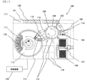
図1において、自動分析装置100は、ラック101を搬送するラック搬送ライン117、反応容器105を設置するインキュベータディスク(反応ディスク)104、試料分注チップや反応容器105を搬送する搬送機構106、試料分注チップや反応容器105を保持する保持部材107、反応容器105内の試料を攪拌する反応容器攪拌機構108、試料を分注、吐出する試料分注装置(試料分注機構)103、試薬容器118を設置した試薬ディスク111、試薬を分注・吐出する試薬分注装置(試薬分注機構)114、インキュベータディスク104及び検出ユニット116間で反応容器105を移載する反応容器搬送機構115、反応容器105内の反応液に含まれる特定の生体成分や化学物質等を検出する検出ユニット116、試薬分注装置114の試薬分注プローブ122(図2に示す)を洗浄するための試薬分注プローブ洗浄装置119及び各装置の動作を制御する制御装置120を備えている。
In FIG. 1, an
ラック搬送ライン117は、当該ラック搬送ライン117上の、所定の場所である試料分注位置までラック101を搬送する。試料分注位置とは試料分注装置103によって試料が分注可能な位置である。ラック101には、試料を保持する試料容器102を複数架設することができる。本実施例では、このように試料をライン搬送する構成を例示しているが、回転して試料を搬送するディスク状のものを設ける場合もある。
The
インキュベータディスク104は、複数の反応容器105を環状に設置する容器設置部を有している。インキュベータディスク104は図示しない駆動装置によって回転駆動され、試料分注装置103による分注位置等を含む各所定位置まで任意の反応容器105を移動させることができる。
The
搬送機構106は、XYZの3軸方向に移動可能であり保持部材107、反応容器攪拌機構108及びインキュベータディスク104の各所定箇所、並びに容器廃棄孔109及び試料分注チップ装着位置110の間で試料分注チップや反応容器を搬送する。
The
保持部材107は、未使用の反応容器105と試料分注チップを複数設置している。上記搬送機構106は、保持部材107の上方に移動し、下降して未使用の反応容器105を把持して上昇し、インキュベータディスク104の所定位置の上方に移動し、下降してインキュベータディスク104に反応容器105を設置する。
The
また、搬送機構106は、保持部材107の上方に移動し、下降して未使用の試料分注チップを把持して上昇し、試料分注チップ装着位置110の上方に移動し、下降して試料分注チップ装着位置110に試料分注チップを設置する。
In addition, the
試料分注装置103は、分注プローブ(図示せず)を回動及び上下方向に移動させる。試料分注チップ装着位置110の上方に分注プローブを回動移動させて降ろし、分注プローブの先端に試料分注チップを圧入して装着する。
The
試料分注チップを装着した分注プローブは、ラック101に載置された試料容器102の上方に移動して下降し、試料容器102に保持された試料を所定量吸引する。試料を吸引した分注プローブは、インキュベータディスク104の上方に移動して下降し、インキュベータディスク104に保持された未使用の反応容器105に試料を吐出する。試料吐出が終了すると、分注プローブは容器廃棄孔109の上方に移動し、使用済みの試料分注チップを容器廃棄孔109から廃棄する。
The dispensing probe equipped with the sample dispensing tip moves and descends above the
試薬ディスク111は、複数の試薬容器118が設置される試薬容器設置部を有する。試薬ディスク111の上部には試薬ディスクカバー112(図1は左部分を一部破断した図である)が設けられていて、試薬ディスク111の内部は所定の温度に保温される。試薬ディスクカバー112には、インキュベータディスク104側の部分に試薬ディスクカバー開口部113が設けられている。
The
試薬分注装置114は、試薬分注プローブ122(図2に示す)を水平方向に移動させる構成のものがあるが、本実施例では試料分注装置103と同じく試薬分注プローブ122を回転方向及び上下方向移動させる構成であってもよい。この試薬分注装置114は、試薬分注プローブ122を試薬ディスクカバー112の開口部113の上方に回転移動させて降ろし、試薬分注プローブ122の先端を所定の試薬容器118に挿入して所定量の試薬を吸引する。その際、試薬ディスク111においては、試薬分注プローブ122に吸引させる試薬を試薬ディスクカバー開口部113の下方位置に予め移動させてある。
The
また、試薬分注装置114には静電容量を用いた液面検知器121(図2に示す)が備わっている。液面センサ121は液面検知器とも称する。液面センサ121は、試薬吸引の際、試薬に対する試薬分注プローブ122の浸漬部が最小限(例えば試薬が必要量だけ吸引できる浸漬量)となるように試薬分注プローブ122の下降量が制御される。
In addition, the
試薬吸引後、試薬分注プローブ122は上昇してインキュベータディスク104の所定位置の上方に回転移動し、反応容器105に試薬を吐出する。その後、次回の試薬吸引工程に移行する前に、洗浄槽の上方に回転移動し、試薬分注プローブ122を洗浄する。
After the reagent is aspirated, the
試料と試薬が吐出された反応容器105は、インキュベータディスク104の回転によって所定位置に移動し、搬送機構106によって反応容器攪拌機構108のところに搬送される。反応容器攪拌機構108は、反応容器105に対して回転運動を加えることで反応容器105内の試料と試薬を攪拌して混和する。攪拌の終了した反応容器105は、搬送機構106によって、インキュベータディスク104の所定位置に戻される。
The
搬送機構115は、試料分注装置103と同じく回転と上下移動が可能である。搬送機構115は試料と試薬の分注及び攪拌が終了しインキュベータディスク104に戻されて所定の反応時間が経過した反応容器105の上方に移動して下降し、反応容器105を把持して上昇し、回転移動によって検出ユニット116に反応容器105を搬送する。
The
なお、本実施例においては、検出ユニット116と搬送機構115を2つずつ設け、並列分析による分析処理効率の倍増が図られている。
In the present embodiment, two
以上で説明した各装置によるプロセス及び以下に説明する試薬分注プローブ洗浄動作は制御装置120によって実行される。制御装置120は、専用の回路基板によってハードウェアとして構成されていてもよいし、自動分析装置に接続されたコンピュータで実行されるソフトウェアによって構成されてもよい。ハードウェアにより構成する場合には、処理を実行する複数の演算器を配線基板上、または半導体チップまたはパッケージ内に集積することにより実現できる。ソフトウェアにより構成する場合には、コンピュータに高速な汎用CPUを搭載して、所望の演算処理を実行するプログラムを実行することで実現できる。このプログラムが記録された記録媒体により、既存の装置をアップグレードすることも可能である。また、これらの装置や回路、コンピュータ間は有線又は無線のネットワークで接続され、適宜データが送受信される。
The process by each apparatus described above and the reagent dispensing probe cleaning operation described below are executed by the
2.試薬分注プローブ洗浄槽の構成
図2は試薬分注装置114及び試薬分注プローブ洗浄装置119を模式的に表した図である。
2. Configuration of Reagent Dispensing Probe Washing Tank FIG. 2 is a diagram schematically showing the
図2において、試薬分注装置114は、試薬分注プローブ122、移動装置123、分注シリンジ200、及び液面検知器121を備えている。移動装置123は、鉛直な軸に一端が連結されたアームを備えていて、駆動装置(図示せず)によってアームを回動させアームの他端に垂設した試薬分注プローブ122を軸周りに回転移動させるとともに、他の駆動装置(図示せず)によってアームを上下動させることで試薬分注プローブ122を上下に移動させる。
In FIG. 2, the
分注シリンジ200は、試薬分注プローブ122に接続していて、試薬分注プローブ122に試薬を吸い込んだり試薬分注プローブ122から試薬を吐出したりする。分注シリンジ200とこの分注シリンジ200及び試薬分注プローブ122を接続する管路には予圧液が吸引されている。
The dispensing
液面検知器121は、試薬分注プローブ122に接続されている。液面検知器121は静電容量によって試薬分注プローブ122を介して試薬や洗浄液の存在を検知する。例えば試薬分注プローブ122が試薬や洗浄液に触れると試薬や洗浄液の存在が液面検知器121によって検知される。なお、特に説明はしないが、試料分注装置103も試薬分注装置114と基本的に同様の構成である。したがって、以下の説明におけるノズル洗浄装置119は試薬分注プローブ、試料分注プローブのいずれを洗浄する場合にも利用することが可能である。
The
図2では、図1に示した試薬分注プローブ洗浄装置119の断面を示している。図2の第一第三吐ノズル201は、分注プローブ122が洗浄位置に移動した状態である。ノズル洗浄装置119は、洗浄槽124、第一第三洗浄液吐出口201、第二洗浄液貯留槽202、第一第三洗浄液供給装置(洗浄液供給機構)125、第二洗浄液供給装置126を備えている。
FIG. 2 shows a cross section of the reagent dispensing
洗浄槽124は、インキュベータディスク104及び試薬ディスク111の間における試薬分注装置114の試薬分注プローブ122の軌道上に配置されている。この洗浄槽124は、試薬分注プローブ122に対して後述する第一洗浄ステップ、第二洗浄ステップ及び第三洗浄ステップをするための容器である。
The
この洗浄槽124内の第一第三洗浄位置には、上記第一第三洗浄液吐出口201が設けられ、第二洗浄位置には、第二洗浄液貯留槽202が設けられている。第一第三洗浄液吐出口201を通して、分注プローブを洗浄する洗浄液が吐出される。ほぼ中心部(分注プローブ122の下方、つまり、第一第三洗浄液吐出口201の下方)には排出口204を備えている。分注プローブ122から吐出される洗浄液は、排出口204に吐出され、排出口204を通して洗浄槽から排出される。洗浄水排出口204は、図示以外の場所の複数個所にも設けても良い。
The first third cleaning
第一第三洗浄位置、第二洗浄位置は試薬分注プローブ122の軌道上にインキュベータディスク104の試薬分注位置から試薬ディスク111の試薬吸引位置に向かってこの配置で並んでいる。図2において、試薬分注プローブ122を破線で表した位置が第二洗浄位置であり、第二洗浄位置の左側に試薬分注プローブ122を実線で表した位置が第一第三洗浄位置である。
The first and third cleaning positions are arranged in this arrangement from the reagent dispensing position of the
なお、試薬分注プローブ122の第一第三洗浄位置は、同一位置を示すが、この第一第三洗浄位置において、第一洗浄ステップと第三洗浄ステップが実行されるため、第一第三洗浄位置と定義している。
The first and third cleaning positions of the
第一第三洗浄位置は、第一第三洗浄液吐出口201から吐出した第一、第三洗浄液が、第一第三洗浄位置にある試薬分注プローブ122の外壁面にかかる位置である。第一第三洗浄液吐出口201は、本実施例では試薬分注プローブ122の移動を妨げない位置に設けられている。
The first third cleaning position is a position where the first and third cleaning liquids discharged from the first third cleaning
第二洗浄液貯留槽202には、この第二洗浄液貯留槽202に第二の洗浄液を供給する第二洗浄液供給装置126が接続されている。第二洗浄液供給装置126は、第二洗浄液を収容するタンク206、送液シリンジ207、流路切換弁208及び電磁弁205を備えている。送液シリンジ207は、タンク206と管路を介して接続している。タンク206と送液シリンジ207とを接続する管路は、分岐して第二洗浄液貯留槽202に接続している。流路切換弁208は管路の分岐部に設けられていて、電磁弁205は流路切換弁208と第二洗浄液貯留槽202とを接続する管路に設けられている。流路切換弁208は送液シリンジ207の接続相手をタンク206及び第二洗浄液貯留槽202のいずれかに切り換える。
A second cleaning
流路切換弁208を介してタンク206に接続した状態で送液シリンジ207が第二洗浄液を吸引し、流路切換弁208により送液シリンジ207の接続先を第二洗浄液貯留槽202に切り換えて、送液シリンジ207から第二洗浄液を吐出することによって、第二洗浄液貯留槽202に第二洗浄液が供給される。電磁弁205、流路切換弁208及び送液シリンジ207は制御装置120からの信号に従って動作する。
The
また、第一第三洗浄液吐出口201には、第一洗浄液及び第三洗浄液を供給する第一第三洗浄液供給装置125が接続されている。第一第三洗浄液吐出装置125は第二洗浄液供給装置126と同様な構成である。このため、簡略的に図示するとともに、その構成については説明を省略する。
The first and third cleaning
3.洗浄手順
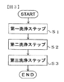
図3は制御装置120による試薬分注プローブの洗浄手順を表したフローチャートである。
3. Cleaning Procedure FIG. 3 is a flowchart showing the cleaning procedure of the reagent dispensing probe by the
図3に示すように、試薬分注プローブの洗浄工程は、第一洗浄ステップS1、第二洗浄ステップS2及び第三洗浄ステップS3の3つのステップを含んでいる。制御装置120は、試薬分注装置114及び試薬分注プローブ洗浄装置119を制御して第一、第二、第三洗浄ステップを実行する。以下、第一、第二、第三洗浄ステップについてそれぞれ説明する。
As shown in FIG. 3, the reagent dispensing probe cleaning process includes three steps of a first cleaning step S1, a second cleaning step S2, and a third cleaning step S3. The
(1)第一洗浄ステップ
第一洗浄ステップでは、制御装置120は、試薬分注装置114の動作を制御して、インキュベータディスク104上の反応容器105に試薬を吐出させた後、移動装置123に信号を出力して試薬分注プローブ122を第一洗浄位置(第一第三洗浄位置)に移動させ、第一第三洗浄液吐口201付近の第一洗浄位置へ移動する。そして、制御装置120は、分注シリンジ200及び第一第三洗浄液供給装置125に信号を出力し、試薬分注プローブ122から予圧液を吐出させるとともに、第一第三洗浄液吐口201から試薬分注プローブ122の外壁面に第一洗浄液をかける。つまり、試薬分注プローブ122内から予圧液を吐出することで試薬分注プローブ122の内壁面を洗浄し、試薬分注プローブ122の外壁面に第一洗浄液をかけることで試薬分注プローブ122の外壁面を洗浄する。
(1) First Washing Step In the first washing step, the
この第一洗浄ステップにおける試薬分注プローブ122の内壁面の洗浄及び外壁面の洗浄はどちらが先でも良く、また同時であっても良い。第一洗浄位置で試薬分注プローブ122の外壁面にかけられた第一洗浄液は、洗浄水排出口204を介して洗浄槽124から排液タンク(図示せず)に排出される。
Either the cleaning of the inner wall surface and the cleaning of the outer wall surface of the
(2)第二洗浄ステップ
第一洗浄ステップ終了後、第二洗浄ステップに手順を移すと、制御装置120は、移動装置123に信号を出力して試薬分注プローブ122を第二洗浄位置の第二洗浄液貯留槽202に移動させ、試薬分注プローブ122の先端を第二洗浄液に浸漬させる。
(2) Second Washing Step After the first washing step, when the procedure is shifted to the second washing step, the
こうして試薬分注プローブ122を第二洗浄位置に移動させたら、制御装置120は、分注シリンジ200に信号を出力して試薬分注プローブ122に第二洗浄液を吸引することで、試薬分注プローブ122の内壁面を洗浄する。
When the
このとき、第二洗浄ステップの実行に伴う第二洗浄液貯留槽202の第二洗浄液の減少に応じて、制御装置120は、第二洗浄液供給装置126に信号を出力して第二洗浄液貯留槽202に第二洗浄液を補充する。つまり、分注プローブ122が吸引する洗浄液の量以上の量の洗浄液を第二洗浄液貯留槽202に補充する。
At this time, according to the decrease of the second cleaning liquid in the second cleaning
(3)第三洗浄ステップ
第二洗浄ステップ終了後、第三洗浄ステップに手順を移すと、制御装置120は、移動装置123に信号を出力して試薬分注プローブ122を第三洗浄位置(第一第三洗浄位置)の第一第三洗浄液吐出口201に移動させ、分注シリンジ200及び第三洗浄液供給装置125に信号を出力し、試薬分注プローブ122から第二洗浄液を吐出して試薬分注プローブ122の内壁面を洗浄するとともに、試薬分注プローブ122の外壁面に第三洗浄液をかけて試薬分注プローブ122の外壁面を洗浄する。
(3) Third washing step After the second washing step, when the procedure is shifted to the third washing step, the
第三洗浄ステップにおける第二洗浄液の吐出及び第三洗浄液の動作は、第一洗浄ステップにおける予圧液の吐出及び第一洗浄液の動作と同様である。この第三洗浄ステップにおける試薬分注プローブ122の内壁面の洗浄及び外壁面の洗浄はどちらが先でも良く、同時であっても良い。第三洗浄位置で試薬分注プローブ122の外壁面にかけられた第三洗浄液は、洗浄水排出口204を介して洗浄槽124から排液タンク(図示せず)に排出される。
The discharge of the second cleaning liquid and the operation of the third cleaning liquid in the third cleaning step are the same as the discharge of the preload liquid and the operation of the first cleaning liquid in the first cleaning step. Either the cleaning of the inner wall surface or the outer wall surface of the
具体的には、例えば、第二洗浄位置から第三洗浄位置への移動速度を遅らせる、第三洗浄位置に到達後第二洗浄液を吐出するタイミングを遅らせる、第二洗浄液を吸引後第二洗浄位置から第三洗浄位置に移動するタイミングを遅らせる等の動作の少なくとも1つにより実行することができる。 Specifically, for example, the moving speed from the second cleaning position to the third cleaning position is delayed, the timing at which the second cleaning liquid is discharged after reaching the third cleaning position is delayed, the second cleaning position after sucking the second cleaning liquid Can be executed by at least one of operations such as delaying the timing of moving to the third cleaning position.
なお、上記第一〜第三洗浄ステップの少なくとも1つにおいて、液面検知器121を用いて洗浄液を検知することで洗浄液の吐出状態又は貯留状態が正常であることを判断することができる。例えば、液面検知器121から入力される信号を基に、制御装置120によって試薬分注プローブ122に洗浄液が触れていることを確認する。そして、第一〜第三洗浄ステップの全てが正常に実行されていることが制御装置120で確認されない場合、正常に実行されなかった洗浄ステップを報知する信号が表示装置や音声装置、印刷装置等の出力装置に制御装置120から出力されるようにすることができる。また、必要であれば第一〜第三洗浄ステップが正常に実行されている旨を報知する信号が表示装置や音声装置、印刷装置等の出力装置に制御装置120から出力されるようにすることもできる。
In at least one of the first to third cleaning steps, it is possible to determine that the discharge state or the storage state of the cleaning liquid is normal by detecting the cleaning liquid using the
4.洗浄液吐出口
(1)洗浄液吐出口からの液滴飛散りメカニズム
図4は洗浄液吐出口からの液滴飛散りのメカニズムを示す。試薬吐出プローブは洗浄槽にてプローブ内流路、及び外側表面の洗浄を行う(図4(a))。水流停止時、慣性によって洗浄液吐出口先端から洗浄水の一部が余分に飛び出し、代わりに空気が入り込む(図4(b))。吐出口内の洗浄水は、流路の中で暫くの間、洗浄液吐出口側と洗浄水供給側に対して振動を起こす。この振動中に洗浄水の一部が洗浄液吐出口の外に飛び出し、洗浄槽外へ飛散る事が有る(図4(c))。洗浄液吐出圧が高い時、洗浄液吐出停止時の洗浄水の振動速度も高くなり、振幅も大きくなる。その結果、一時的に洗浄液吐出口の外に飛び出す洗浄水の体積が大きくなり、また、速度も高くなることで、洗浄液吐出口からの液滴飛散り発生頻度が高くなる。液面の振動速度が速い場合、空気が洗浄液吐出口内の洗浄水の液面に潜り込む事が有る。その結果、洗浄液吐出口先端内部の洗浄水で満たされている領域に空気層が形成される。または、振動停止後に吐出口先端内壁に残った液膜が表面張力によって集まり、新たな洗浄水層が形成される(図4(d))。そして、次の動作サイクルで新たに洗浄水が吐出される際、新たに形成された洗浄水層が洗浄液吐出口先端から押し出され、次に空気層が吐き出される。洗浄水層が吐出される際、洗浄水層の移動によって、空気層と洗浄液吐出口内壁の間に新たに液膜が形成される。洗浄水層の吐出が終了し、空気層が吐出される際、この液膜が洗浄液吐出口先端で気泡となることがある。この気泡が破裂することによって、液滴が周囲に飛び散る。または、空気層に残った液膜が表面張力によって小さな液滴となり、空気層と一緒に吐出される。この時、小さな液滴は洗浄液吐出口内壁との表面張力と空気層の押し出される力のバランスにより、洗浄水が吐出される方向とは別の方向へ飛んでいくことがある(図4(e))。洗浄液吐出圧が高い時、空気層の吐出速度も高くなるため、気泡破裂時の飛散り、小さな液滴の飛び散りの発生頻度は高くなる。
4). Cleaning Liquid Discharge Port (1) Droplet Scattering Mechanism from Cleaning Liquid Discharge Port FIG. 4 shows a mechanism of droplet scattering from the cleaning liquid discharge port. The reagent discharge probe cleans the flow path in the probe and the outer surface in the cleaning tank (FIG. 4A). When the water flow is stopped, a part of the cleaning water jumps out from the front end of the cleaning liquid discharge port due to inertia, and air enters instead (FIG. 4B). The cleaning water in the discharge port vibrates for a while in the flow path on the cleaning liquid discharge port side and the cleaning water supply side. During this vibration, part of the cleaning water may jump out of the cleaning liquid discharge port and scatter out of the cleaning tank (FIG. 4C). When the cleaning liquid discharge pressure is high, the vibration speed of the cleaning water when the cleaning liquid discharge is stopped increases and the amplitude also increases. As a result, the volume of the cleaning water that temporarily jumps out of the cleaning liquid discharge port is increased and the speed is increased, so that the frequency of occurrence of droplet scattering from the cleaning liquid discharge port is increased. When the vibration speed of the liquid level is high, air may enter the liquid level of the cleaning water in the cleaning liquid discharge port. As a result, an air layer is formed in a region filled with the cleaning water inside the cleaning liquid discharge port tip. Alternatively, the liquid film remaining on the inner wall of the discharge port after the vibration is stopped gathers due to surface tension, and a new washing water layer is formed (FIG. 4D). Then, when the cleaning water is newly discharged in the next operation cycle, the newly formed cleaning water layer is pushed out from the tip of the cleaning liquid discharge port, and then the air layer is discharged. When the cleaning water layer is discharged, a liquid film is newly formed between the air layer and the inner wall of the cleaning liquid discharge port due to the movement of the cleaning water layer. When the discharge of the cleaning water layer is completed and the air layer is discharged, the liquid film may become bubbles at the front end of the cleaning liquid discharge port. When the bubbles burst, droplets scatter around. Alternatively, the liquid film remaining in the air layer becomes small droplets due to the surface tension and is discharged together with the air layer. At this time, a small droplet may fly in a direction different from the direction in which the cleaning water is discharged due to the balance between the surface tension with the inner wall of the cleaning liquid discharge port and the force with which the air layer is pushed out (FIG. 4 (e)). )). When the cleaning liquid discharge pressure is high, the discharge speed of the air layer is also increased, so that the frequency of occurrence of bubbles at the time of bursting bubbles and small droplets is increased.
(2)第一の洗浄液吐出口形態による飛散り防止
次に、本実施例における第一の洗浄液吐出口形態について説明する。
(2) Spattering prevention by first cleaning liquid discharge port configuration Next, a first cleaning liquid discharge port configuration in the present embodiment will be described.
図5は本実施例に係る自動分析装置に備えられた洗浄液吐出口の形状と効果の一例を説明した図である。 FIG. 5 is a diagram for explaining an example of the shape and effect of the cleaning liquid discharge port provided in the automatic analyzer according to the present embodiment.
図5の例では洗浄液吐出口の開口面が洗浄水排出口側に向かい合うように開放されている。具体的には、洗浄槽の側面から見た場合、洗浄液吐出口先端が洗浄槽排水口に対して水平、あるいは洗浄槽の側壁側に傾いた形状をしている。つまり、洗浄水吐出口先端が洗浄槽排水口または洗浄槽の側壁に向かい合うように開口している。また、洗浄液吐出口先端は真正面(洗浄水吐出ノズルの軸方向)から見た場合、正円になっており、先端の開口面に対して鉛直方向から見た場合は楕円形になっている。(図5(a))。図5の例で示した洗浄液吐出口を用いて洗浄液吐出を行った場合、先端構造が洗浄水排出口側に開放されていることで、洗浄液吐出停止時の振動によって洗浄液吐出口から飛び出す一部の洗浄水が、洗浄水排出口側に向く。これにより液滴の飛び散り方向が洗浄水排出口側に制限され、洗浄槽外への飛び散りが抑制される(図5(b))。また、同様に空気層吐出時の飛び散りも洗浄水排出口側に制限され、洗浄槽外への飛び散りが抑制される(図5(d))。ある一例によれば、洗浄水は内径2〜4 mmの洗浄液吐出口から流速 350〜450 (mm/sec)で吐出される。特に洗浄液吐出停止後の洗浄水振動時に吐出口先端から洗浄水が飛び出し、吐出口先端の外側に付着しない範囲で水圧が調整されていた時、飛び散り防止効果が最大となる。 In the example of FIG. 5, the opening surface of the cleaning liquid discharge port is opened so as to face the cleaning water discharge port side. Specifically, when viewed from the side surface of the cleaning tank, the tip of the cleaning liquid discharge port has a shape that is horizontal with respect to the cleaning tank drain or inclined toward the side wall of the cleaning tank. That is, the cleaning water discharge port is open so that the tip of the cleaning water discharge port faces the cleaning tank drain port or the side wall of the cleaning tank. Further, the front end of the cleaning liquid discharge port is a perfect circle when viewed from the front (axial direction of the cleaning water discharge nozzle), and is elliptical when viewed from the vertical direction with respect to the opening surface of the front end. (FIG. 5 (a)). When the cleaning liquid discharge is performed using the cleaning liquid discharge port shown in the example of FIG. 5, the tip structure is open to the cleaning water discharge port side, so that a part of the cleaning liquid discharge port jumps out due to vibration when the cleaning liquid discharge is stopped The cleaning water is directed to the cleaning water discharge side. As a result, the direction in which the droplets scatter is limited to the cleaning water discharge port side, and scattering outside the cleaning tank is suppressed (FIG. 5B). Similarly, scattering when discharging the air layer is also limited to the cleaning water discharge port side, and scattering outside the cleaning tank is suppressed (FIG. 5D). According to an example, the cleaning water is discharged at a flow rate of 350 to 450 (mm / sec) from a cleaning liquid discharge port having an inner diameter of 2 to 4 mm. In particular, when the cleaning water oscillates after the cleaning liquid discharge is stopped and the water pressure is adjusted within a range where the cleaning water jumps out from the front end of the discharge port and does not adhere to the outside of the front end of the discharge port, the scattering prevention effect is maximized.
(3)第二の洗浄水吐出口形態による飛散り防止
次に、本実施例における第二の洗浄水吐出口形態について説明する。
(3) Scattering prevention by second cleaning water discharge port configuration Next, a second cleaning water discharge port configuration in the present embodiment will be described.
図6は第二の実施例に係る自動分析装置に備えられた洗浄液吐出口の形状と効果を説明した図である。 FIG. 6 is a diagram for explaining the shape and effect of the cleaning liquid discharge port provided in the automatic analyzer according to the second embodiment.
図6の例が図5の例と相違する点は、洗浄液吐出口の先端部分がツバ状の構造をしている点である。具体的には、真正面(洗浄水吐出ノズルの軸方向)から見た場合、洗浄液吐出口の輪郭は正円となっており少なくとも有る一側面((洗浄水吐出ノズルの軸に垂直な方向)から見た場合にノズル先端の輪郭線が非直線になっている。例えば図6の例では洗浄水吐出ノズルの軸に垂直な方向から見た場合にノズル先端の輪郭線はL字型になっている。また、この輪郭線が曲線状であってもよいし2段以上の階段形状となっている形状であってもよい。図6の例では、洗浄槽外側で吐出口先端が長く、洗浄水排出口側で短くなるように洗浄液吐出口を配置している。言い換えれば、ノズル軸方向から見た先端外周において、洗浄液吐出口の長さが洗浄槽排出口側より洗浄槽外側の方が長くなっている。この長くなっている部分をツバ部分と呼ぶ。ツバの長さは例えば3〜5 mmである。ツバ部分は洗浄液吐出口の先端外周の120°以上を占める構造であることが望ましい。また、円筒部分の断面積とツバ部分を含む先端構造内壁部分の表面積の比は1:3〜4.3である。(図6(a))。尚、洗浄液吐出口の先端構造は洗浄液吐出口先端の一部を切削することで加工されても良いし、洗浄液吐出口と一体成型されてもよい。また、上述したようなツバ状の構造を有する部材を洗浄液吐出口の円筒部分に被せるように形成しても良い。 The example of FIG. 6 is different from the example of FIG. 5 in that the tip portion of the cleaning liquid discharge port has a brim-like structure. Specifically, when viewed from the front (axial direction of the cleaning water discharge nozzle), the contour of the cleaning liquid discharge port is a perfect circle and is at least from one side surface (the direction perpendicular to the axis of the cleaning water discharge nozzle). The contour of the nozzle tip is non-linear when viewed, for example, in the example of Fig. 6, the contour of the nozzle tip is L-shaped when viewed from the direction perpendicular to the axis of the cleaning water discharge nozzle. In addition, the contour line may be a curved line or a shape having two or more steps.In the example of FIG. In other words, the length of the cleaning liquid discharge port is longer on the outer side of the cleaning tank than on the cleaning tank discharge port side at the outer periphery of the tip as viewed from the nozzle axial direction. This long part is called the brim part. The length is, for example, 3 to 5 mm, and the brim portion preferably has a structure that occupies 120 ° or more of the outer periphery of the tip of the cleaning liquid discharge port, and the inner wall portion of the tip structure including the cross-sectional area of the cylindrical portion and the brim portion. The surface area ratio is 1: 3 to 4.3 (FIG. 6A) The tip structure of the cleaning liquid discharge port may be processed by cutting a part of the cleaning liquid discharge port tip, It may be formed integrally with the cleaning liquid discharge port, or may be formed so as to cover the cylindrical portion of the cleaning liquid discharge port with the above-described brim-like structure.
第二の実施例で示した洗浄液吐出口を用いて洗浄液吐出を行った場合、先端がツバ状の構造をしていることで、吐出停止後に吐出口から飛び出す洗浄水が出口長辺側の内壁に付着したまま、洗浄水排出口側に露出する形になる。別の表現をすれば、洗浄槽外側から見て、洗浄液吐出口先端は飛び出した洗浄水を隠す状態となる。その為、洗浄液吐出停止時に発生する飛び散りのうち、洗浄槽外側方向への飛び散りが起こらなくなり、洗浄水排出口側に制限される。別の表現をすれば、洗浄水排出口側にのみ洗浄水が飛び出すようになるため、洗浄槽外側への飛び散りは抑制される(図6(b))。 When the cleaning liquid is discharged using the cleaning liquid discharge port shown in the second embodiment, the tip of the tip has a brim-like structure, so that the cleaning water jumping out from the discharge port after stopping the discharge is the inner wall on the outlet long side It is exposed to the cleaning water discharge port side while adhering to the surface. In other words, when viewed from the outside of the cleaning tank, the tip of the cleaning liquid discharge port is in a state of concealing the protruding cleaning water. For this reason, of the splatters generated when the cleaning liquid discharge is stopped, splattering toward the outer side of the cleaning tank does not occur, and the cleaning water discharge port side is limited. In other words, since the cleaning water jumps out only to the cleaning water discharge port side, scattering to the outside of the cleaning tank is suppressed (FIG. 6B).
また、前述のようにノズル先端に空気層が残る事がある(図6(c))。図6の形状の洗浄液吐出口によれば、空気層吐出時の飛び散りでは、空気層吐出の際に生じる気泡が洗浄水排出口側に向かって膨張、破裂するため、洗浄槽外への飛散りは抑制される。最初の洗浄水層移動に伴って生じる空気層内の液滴は、洗浄液吐出口短辺側にある時、空気層の吐出と共に飛散りを起こすが、洗浄槽外側への飛散りはツバにより妨げられる。一方、液滴が洗浄液吐出口長辺側に付着している時、空気層の吐出に伴いツバ部分まで押し出される。しかしながら、反対方向である短辺側が開放されているため、ツバ部分では押し出される力が弱まり、飛散りに至らない。このような液滴は空気層吐出後に吐出される本流の洗浄水と共に吐出され、洗浄槽外側へは飛び散らない(図6(d))。 In addition, an air layer may remain at the nozzle tip as described above (FIG. 6C). According to the cleaning liquid discharge port having the shape shown in FIG. 6, when the air layer is spattered, bubbles generated during the air layer discharge expand and burst toward the cleaning water discharge port. Is suppressed. The droplets in the air layer that accompany the first cleaning water layer movement are scattered along with the discharge of the air layer when it is on the short side of the cleaning liquid discharge port. It is done. On the other hand, when the droplet is attached to the long side of the cleaning liquid discharge port, it is pushed out to the brim portion as the air layer is discharged. However, since the short side which is the opposite direction is open, the force pushed out at the brim portion is weakened and does not scatter. Such droplets are discharged together with the main-stream cleaning water discharged after the air layer is discharged, and are not scattered outside the cleaning tank (FIG. 6D).
図6の例では、図5の例と同様に、例えば洗浄水は内径2〜4 mmの洗浄液吐出口から流速 350〜450 (mm/sec)で吐出される。特に洗浄液吐出停止後の洗浄液振動時に吐出口先端から飛び出す洗浄水がツバ部分から飛び出さない範囲において、最大の飛び散り防止効果を示す。 In the example of FIG. 6, as in the example of FIG. 5, for example, cleaning water is discharged at a flow rate of 350 to 450 (mm / sec) from a cleaning liquid discharge port having an inner diameter of 2 to 4 mm. In particular, in the range in which the cleaning water that jumps out from the tip of the discharge port when the cleaning liquid vibrates after stopping the discharge of the cleaning liquid does not jump out from the flange portion, the maximum scattering prevention effect is shown.
(4)本実施例による液滴飛散りの付着、混入の防止と洗浄効率向上
洗浄効率向上の為に洗浄水圧を上げると、第一第三洗浄液吐出口201からの洗浄水飛散りも増加し、試薬分注プローブ122への洗浄水付着、または反応容器へ混入、希釈が発生する可能性がある。しかしながら、本実施例に述べた洗浄ノズルによれば、洗浄水飛び散り発生頻度を上げることなく洗浄水圧を上げることが可能となり、試薬分注プローブ122の洗浄効率を向上させることができる。
(4) Prevention of adhering and mixing of droplets and improvement of cleaning efficiency according to this embodiment When cleaning water pressure is increased to improve cleaning efficiency, cleaning water scattering from the first third cleaning
100・・・自動分析装置、101・・・ラック、102・・・試料容器、103・・・試料分注装置、104・・・インキュベータディスク(反応ディスク)、105・・・反応容器、106・・・搬送機構、107・・・保持部材、108・・・反応容器撹拌機構、109・・・容器廃棄孔、110・・・試料分注チップ装着位置、111・・・試薬ディスク、112・・・試薬ディスクカバー、113・・・試薬ディスクカバー開口部、114・・・試薬分注装置、115・・・容器搬送機構、116・・・検出ユニット(検出部)、117・・・ラック搬送ライン、118・・・試薬容器、119・・・試薬分注プローブ洗浄装置、120・・・制御装置、121・・・液面検知器、122・・・試薬分注プローブ、123・・・移動装置、124・・・洗浄槽、125・・・第一第三洗浄水供給装置、126・・・第二洗浄水供給装置、200・・・分注シリンジ、201・・・第一第三洗浄液吐出口、202・・・第二洗浄液貯留槽、204・・・洗浄水排出口、205、208、・・・電磁弁、206・・・タンク、207・・・送液シリンジ
DESCRIPTION OF
Claims (9)
前記分注プローブを洗浄する洗浄液を吐出する洗浄液吐出口を有する洗浄液吐出口と、
前記洗浄液吐出口の下方に設けられ前記洗浄液を排出する洗浄槽排出口を有する洗浄槽と、を備え、
前記洗浄液吐出口は、当該洗浄水吐出口先端の開口部が前記洗浄槽排出口または前記洗浄槽の側壁に向かい合うように開放された形状である自動分析装置。 A dispensing probe for dispensing a sample or reagent; and
A cleaning liquid discharge port having a cleaning liquid discharge port for discharging a cleaning liquid for cleaning the dispensing probe;
A cleaning tank provided below the cleaning liquid discharge port and having a cleaning tank discharge port for discharging the cleaning liquid;
The cleaning liquid discharge port is an automatic analyzer having a shape that is open such that the opening at the tip of the cleaning water discharge port faces the cleaning tank discharge port or the side wall of the cleaning tank.
前記洗浄液吐出口の先端がツバ状の構造であって、
当該ツバ状の構造は、前記洗浄液吐出口の軸方向から見た場合当該洗浄液吐出口の輪郭は正円であり、前記洗浄液吐出口の軸に垂直な方向であって前記洗浄液吐出口の側面から見た場合、当該洗浄液吐出口の輪郭は非直線状である自動分析装置。 The automatic analyzer according to claim 1,
The tip of the cleaning liquid discharge port has a brim-like structure,
The brim-like structure, when viewed from the axial direction of the cleaning liquid discharge port, has a perfect circular outline, and is perpendicular to the axis of the cleaning liquid discharge port and from the side surface of the cleaning liquid discharge port. An automatic analyzer that has a non-linear outline when viewed.
前記ツバ状の構造は、前記洗浄液吐出口の軸に垂直な方向であって前記洗浄液吐出口の側面から見た場合、当該洗浄液吐出口の輪郭はL字型である自動分析装置。 The automatic analyzer according to claim 2,
The automatic analysis apparatus, wherein the brim-like structure is in a direction perpendicular to the axis of the cleaning liquid discharge port and has an L-shaped outline when viewed from the side surface of the cleaning liquid discharge port.
前記ツバ状の構造は前記洗浄液吐出口の一部を切削して形成され、または前記洗浄液吐出口と一体成型されている自動分析装置。 The automatic analyzer according to claim 2,
The collar-like structure is an automatic analyzer formed by cutting a part of the cleaning liquid discharge port or integrally formed with the cleaning liquid discharge port.
前記ツバ状の構造は、当該ツバ状の構造を有する部材を前記洗浄液吐出口に取り付けることで形成される自動分析装置。 The automatic analyzer according to claim 2,
The brim-like structure is an automatic analyzer formed by attaching a member having the brim-like structure to the cleaning liquid discharge port.
前記ツバ状の構造は、前記洗浄液吐出口の軸方向から見た前記洗浄液吐出口の先端外周において、前記洗浄液吐出口の長さが前記洗浄槽排出口の側より前記洗浄槽の外側の方が長い形状である自動分析装置。 The automatic analyzer according to claim 2,
The collar-shaped structure is such that the length of the cleaning liquid discharge port is longer on the outer side of the cleaning tank than on the cleaning tank discharge port side at the outer periphery of the cleaning liquid discharge port as viewed from the axial direction of the cleaning liquid discharge port. Automatic analyzer with long shape.
前記ツバ状の構造は、前記洗浄水吐出口の軸方向から見た前記洗浄液吐出口の先端外周のうち120°以上を占める部分において前記洗浄液吐出口の長さが前記洗浄槽排出口の側より前記洗浄槽の外側の方が長い形状である自動分析装置。 The automatic analyzer according to claim 6,
The brim-like structure is such that the length of the cleaning liquid discharge port is longer than the cleaning tank discharge port side at a portion occupying 120 ° or more of the outer periphery of the front end of the cleaning liquid discharge port as viewed from the axial direction of the cleaning water discharge port. An automatic analyzer in which the outside of the washing tank has a longer shape.
前記洗浄水吐出ノズルの円筒部分の断面積と、前記ツバ状の構造における前記洗浄液吐出口によって開口された内壁部分の表面積の比は1:3〜4.3である自動分析装置。 The automatic analyzer according to claim 2,
An automatic analyzer in which a ratio of a cross-sectional area of a cylindrical portion of the cleaning water discharge nozzle to a surface area of an inner wall portion opened by the cleaning liquid discharge port in the brim-like structure is 1: 3 to 4.3.
前記洗浄液吐出口の内径は2mm以上〜4mm以下であって、
前記洗浄液吐出口からの前記洗浄液の流速が350mm/sec以上450mm/sec以下である自動分析装置。 The automatic analyzer according to claim 1,
The cleaning liquid discharge port has an inner diameter of 2 mm to 4 mm,
An automatic analyzer in which a flow rate of the cleaning liquid from the cleaning liquid discharge port is 350 mm / sec or more and 450 mm / sec or less.
Priority Applications (1)
| Application Number | Priority Date | Filing Date | Title |
|---|---|---|---|
| JP2015121635A JP6626642B2 (en) | 2015-06-17 | 2015-06-17 | Automatic analyzer |
Applications Claiming Priority (1)
| Application Number | Priority Date | Filing Date | Title |
|---|---|---|---|
| JP2015121635A JP6626642B2 (en) | 2015-06-17 | 2015-06-17 | Automatic analyzer |
Publications (2)
| Publication Number | Publication Date |
|---|---|
| JP2017009299A true JP2017009299A (en) | 2017-01-12 |
| JP6626642B2 JP6626642B2 (en) | 2019-12-25 |
Family
ID=57761401
Family Applications (1)
| Application Number | Title | Priority Date | Filing Date |
|---|---|---|---|
| JP2015121635A Active JP6626642B2 (en) | 2015-06-17 | 2015-06-17 | Automatic analyzer |
Country Status (1)
| Country | Link |
|---|---|
| JP (1) | JP6626642B2 (en) |
Cited By (4)
| Publication number | Priority date | Publication date | Assignee | Title |
|---|---|---|---|---|
| JPWO2020230403A1 (en) * | 2019-05-15 | 2020-11-19 | ||
| WO2021112120A1 (en) * | 2019-12-05 | 2021-06-10 | 株式会社日立ハイテク | Automatic analysis device |
| CN113311163A (en) * | 2020-02-26 | 2021-08-27 | 深圳迈瑞生物医疗电子股份有限公司 | Cleaning method of detection pool |
| WO2022224521A1 (en) * | 2021-04-20 | 2022-10-27 | 株式会社日立ハイテク | Automatic analysis device and method for controlling same |
Citations (5)
| Publication number | Priority date | Publication date | Assignee | Title |
|---|---|---|---|---|
| JPH02284658A (en) * | 1988-12-28 | 1990-11-22 | Nippondenso Co Ltd | Needle-like nozzle inserted into pore |
| JP2003088812A (en) * | 2001-09-20 | 2003-03-25 | Furuno Electric Co Ltd | Nozzle cleaning device |
| WO2010016506A1 (en) * | 2008-08-07 | 2010-02-11 | 株式会社 日立ハイテクノロジーズ | Automatic analyzing device |
| JP2011214842A (en) * | 2010-03-31 | 2011-10-27 | Tosoh Corp | Dispenser nozzle |
| JP2013246055A (en) * | 2012-05-25 | 2013-12-09 | Toshiba Corp | Autoanalyzer |
-
2015
- 2015-06-17 JP JP2015121635A patent/JP6626642B2/en active Active
Patent Citations (5)
| Publication number | Priority date | Publication date | Assignee | Title |
|---|---|---|---|---|
| JPH02284658A (en) * | 1988-12-28 | 1990-11-22 | Nippondenso Co Ltd | Needle-like nozzle inserted into pore |
| JP2003088812A (en) * | 2001-09-20 | 2003-03-25 | Furuno Electric Co Ltd | Nozzle cleaning device |
| WO2010016506A1 (en) * | 2008-08-07 | 2010-02-11 | 株式会社 日立ハイテクノロジーズ | Automatic analyzing device |
| JP2011214842A (en) * | 2010-03-31 | 2011-10-27 | Tosoh Corp | Dispenser nozzle |
| JP2013246055A (en) * | 2012-05-25 | 2013-12-09 | Toshiba Corp | Autoanalyzer |
Cited By (8)
| Publication number | Priority date | Publication date | Assignee | Title |
|---|---|---|---|---|
| JPWO2020230403A1 (en) * | 2019-05-15 | 2020-11-19 | ||
| WO2020230403A1 (en) * | 2019-05-15 | 2020-11-19 | 株式会社日立ハイテク | Automatic analyzing device |
| JP7281540B2 (en) | 2019-05-15 | 2023-05-25 | 株式会社日立ハイテク | automatic analyzer |
| WO2021112120A1 (en) * | 2019-12-05 | 2021-06-10 | 株式会社日立ハイテク | Automatic analysis device |
| JP7455142B2 (en) | 2019-12-05 | 2024-03-25 | 株式会社日立ハイテク | automatic analyzer |
| CN113311163A (en) * | 2020-02-26 | 2021-08-27 | 深圳迈瑞生物医疗电子股份有限公司 | Cleaning method of detection pool |
| CN113311163B (en) * | 2020-02-26 | 2024-04-12 | 深圳迈瑞生物医疗电子股份有限公司 | Cleaning method of detection pool |
| WO2022224521A1 (en) * | 2021-04-20 | 2022-10-27 | 株式会社日立ハイテク | Automatic analysis device and method for controlling same |
Also Published As
| Publication number | Publication date |
|---|---|
| JP6626642B2 (en) | 2019-12-25 |
Similar Documents
| Publication | Publication Date | Title |
|---|---|---|
| JP6466846B2 (en) | Nozzle cleaning method and automatic analyzer | |
| JP5744923B2 (en) | Automatic analyzer | |
| JP6626642B2 (en) | Automatic analyzer | |
| JP5554418B2 (en) | Automatic analyzer | |
| JP2016191561A (en) | Dispensing nozzle washing method and automatic analyzer | |
| WO2017145672A1 (en) | Automated analysis device and cleaning method | |
| JP2017015452A (en) | Automatic analyzer | |
| JPH01141357A (en) | Sample partial injection method for automatic analyzing device | |
| WO2018155042A1 (en) | Automated analyzer | |
| JPWO2015111469A1 (en) | Automatic analyzer | |
| JP5111328B2 (en) | Automatic analyzer | |
| WO2020071163A1 (en) | Automated analyzer | |
| WO2020230403A1 (en) | Automatic analyzing device | |
| JP2009031174A (en) | Autoanalyzer | |
| JP7458882B2 (en) | Automatic analyzer, dispensing device and dispensing control method | |
| JP2011106828A (en) | Dispensing device, automated analysis apparatus, and dispensing method | |
| JP2005249535A (en) | Dispensation probe and autoanalyzer equipped therewith | |
| JP7105230B2 (en) | Automatic analyzer and analysis method | |
| US20220034927A1 (en) | Automated analyzer and cleaning method | |
| JP6004398B2 (en) | Automatic analyzer | |
| WO2021215068A1 (en) | Dispensing device, automated analysis device, and dispensing method | |
| WO2022149332A1 (en) | Automatic analysis device and method for controlling same | |
| JP2013148360A (en) | Automatic analyzer, dispensation mechanism, and dispensation method | |
| JPS6370169A (en) | Cleaning of probe | |
| JP2013253826A (en) | Stirring rod washing mechanism and automatic analyzer |
Legal Events
| Date | Code | Title | Description |
|---|---|---|---|
| A521 | Request for written amendment filed |
Free format text: JAPANESE INTERMEDIATE CODE: A523 Effective date: 20150619 |
|
| RD04 | Notification of resignation of power of attorney |
Free format text: JAPANESE INTERMEDIATE CODE: A7424 Effective date: 20170119 |
|
| RD04 | Notification of resignation of power of attorney |
Free format text: JAPANESE INTERMEDIATE CODE: A7424 Effective date: 20170125 |
|
| RD02 | Notification of acceptance of power of attorney |
Free format text: JAPANESE INTERMEDIATE CODE: A7422 Effective date: 20170803 |
|
| RD04 | Notification of resignation of power of attorney |
Free format text: JAPANESE INTERMEDIATE CODE: A7424 Effective date: 20170804 |
|
| A621 | Written request for application examination |
Free format text: JAPANESE INTERMEDIATE CODE: A621 Effective date: 20180214 |
|
| A977 | Report on retrieval |
Free format text: JAPANESE INTERMEDIATE CODE: A971007 Effective date: 20181030 |
|
| A131 | Notification of reasons for refusal |
Free format text: JAPANESE INTERMEDIATE CODE: A131 Effective date: 20181106 |
|
| A521 | Request for written amendment filed |
Free format text: JAPANESE INTERMEDIATE CODE: A523 Effective date: 20181218 |
|
| A131 | Notification of reasons for refusal |
Free format text: JAPANESE INTERMEDIATE CODE: A131 Effective date: 20190507 |
|
| A521 | Request for written amendment filed |
Free format text: JAPANESE INTERMEDIATE CODE: A523 Effective date: 20190619 |
|
| TRDD | Decision of grant or rejection written | ||
| A01 | Written decision to grant a patent or to grant a registration (utility model) |
Free format text: JAPANESE INTERMEDIATE CODE: A01 Effective date: 20191105 |
|
| A61 | First payment of annual fees (during grant procedure) |
Free format text: JAPANESE INTERMEDIATE CODE: A61 Effective date: 20191202 |
|
| R150 | Certificate of patent or registration of utility model |
Ref document number: 6626642 Country of ref document: JP Free format text: JAPANESE INTERMEDIATE CODE: R150 |
|
| S531 | Written request for registration of change of domicile |
Free format text: JAPANESE INTERMEDIATE CODE: R313531 |
|
| S533 | Written request for registration of change of name |
Free format text: JAPANESE INTERMEDIATE CODE: R313533 |
|
| R350 | Written notification of registration of transfer |
Free format text: JAPANESE INTERMEDIATE CODE: R350 |