JP2017009082A - Hydraulic operation device - Google Patents
Hydraulic operation device Download PDFInfo
- Publication number
- JP2017009082A JP2017009082A JP2015127317A JP2015127317A JP2017009082A JP 2017009082 A JP2017009082 A JP 2017009082A JP 2015127317 A JP2015127317 A JP 2015127317A JP 2015127317 A JP2015127317 A JP 2015127317A JP 2017009082 A JP2017009082 A JP 2017009082A
- Authority
- JP
- Japan
- Prior art keywords
- hydraulic
- control valve
- work
- turning
- operation lever
- Prior art date
- Legal status (The legal status is an assumption and is not a legal conclusion. Google has not performed a legal analysis and makes no representation as to the accuracy of the status listed.)
- Pending
Links
Images


Abstract
Description
本発明は、リモコンバルブの操作装置に関し、操作レバーを操作して二つの油圧アクチュエーターを同時に作動させるときに、一方の油圧アクチュエーターへの作動油の送油を制限し、他方の油圧アクチュエーターの作動が停止しないように操作できる操作装置の技術に関する。 The present invention relates to an operation device for a remote control valve. When operating two operating actuators simultaneously by operating an operating lever, the oil supply to one hydraulic actuator is limited, and the operation of the other hydraulic actuator is restricted. The present invention relates to a technique of an operation device that can be operated without stopping.
従来、第一、第二、及び第三油圧ポンプにて、ブーム、アーム、及びバケットの駆動用、及び本体部旋回用の各油圧アクチュエーターに圧油を供給する掘削旋回作業機の油圧回路において、各油圧アクチュエーターを単独で駆動する場合に、ブーム駆動時は第一及び第三油圧ポンプにて、アーム駆動時は第二及び第三油圧ポンプにて、バケット駆動時は第一油圧ポンプにて、本体部旋回時には第三油圧ポンプにて、それぞれの油圧アクチュエーターに圧油を供給する構成の技術が公知となっている(例えば特許文献1参照)。
また、オペレータが操作レバーを操作した時に、アクチュエーターの負荷に応じた操作感覚が得られるようにした技術も公知となっている(例えば特許文献2参照)。
Conventionally, in the hydraulic circuit of the excavation turning work machine for supplying pressure oil to the hydraulic actuators for driving the boom, arm, and bucket, and for turning the main body by the first, second, and third hydraulic pumps, When each hydraulic actuator is driven independently, the first and third hydraulic pumps are used for boom driving, the second and third hydraulic pumps are used for arm driving, and the first hydraulic pump is used for bucket driving. A technique of supplying pressure oil to each hydraulic actuator by a third hydraulic pump when the main body turns is known (see, for example, Patent Document 1).
A technique is also known in which an operation feeling corresponding to the load of an actuator is obtained when an operator operates an operation lever (see, for example, Patent Document 2).
前記特許文献1の技術において、外部油圧作業機を取り付けて作動させる場合、予め設けられた外部取出用のPTOポートには、第二油圧ポンプと第三油圧ポンプから圧油が供給されるようになっていた。この場合、例えば、外部油圧作業機として、作業時の作動油流量が多い草刈機を装着して作業をしているときに、草刈作業を行いながら旋回操作をすると、二つの油圧ポンプのうち第三油圧ポンプからの圧油の全量が旋回に費やされることになる。このときに旋回の負荷とPTOの負荷が高い場合は可変ポンプのトルク制御により第二油圧ポンプの流量は極端に減ってしまい、外部油圧作業機(PTO)への送油量も減少して回転数が減少してしまう。つまり、草刈作業時に旋回操作すると、外部油圧作業機の回転速度が低下して、回転軸に草が絡まり易くなり、草が絡むと負荷が大きくなり、作動油圧が高くなってリリーフバルブが動作し、停止することがあった。 In the technique of Patent Document 1, when an external hydraulic working machine is attached and operated, pressure oil is supplied from a second hydraulic pump and a third hydraulic pump to a PTO port for external extraction provided in advance. It was. In this case, for example, when a work is performed with a mower having a large hydraulic oil flow rate at the time of working as an external hydraulic working machine, if the turning operation is performed while the mowing work is performed, the first of the two hydraulic pumps The whole amount of pressure oil from the three hydraulic pumps will be spent on turning. If the turning load and the PTO load are high at this time, the flow rate of the second hydraulic pump is extremely reduced by the torque control of the variable pump, and the amount of oil supplied to the external hydraulic work machine (PTO) is also reduced. The number will decrease. In other words, if the turning operation is performed during mowing work, the rotation speed of the external hydraulic working machine decreases, and grass tends to get entangled with the rotating shaft. Had to stop.
また、操作レバーの操作により、旋回速度を落とすことで、旋回モータへの送油量を適宜抑えて、残りを外部油圧作業機側へ送油して合流させて、外部油圧作業機の回転数を確保できるような操作レバーの操作位置にして、外部油圧作業機の回転速度を維持することも可能であるが、その操作はオペレータの感覚(技量)に依存するため、熟練者でないかぎり難しい操作となっていた。 Also, by reducing the turning speed by operating the operation lever, the amount of oil supplied to the turning motor is appropriately suppressed, and the remaining oil is supplied to the external hydraulic work machine side to be merged. It is also possible to maintain the rotational speed of the external hydraulic work machine by setting the operating position of the operating lever so that it can be secured, but the operation depends on the operator's sense (skill), so it is difficult unless you are an expert It was.
本発明の解決しようとする課題は以上の如くであり、次にこの課題を解決するための手段を説明する。
即ち、請求項1においては、傾倒操作される操作レバーの基部にカムが設けられ、該カムに制御弁のスプールの一端に連結されるプッシュロッドの先端が当接され、該プッシュロッドの近傍に操作レバーの回動を設定角度から制限する回動制限付与手段が着脱可能に設けられるものである。
The problem to be solved by the present invention is as described above. Next, means for solving the problem will be described.
That is, in claim 1, a cam is provided at the base of the operation lever to be tilted, and the tip of the push rod connected to one end of the spool of the control valve is brought into contact with the cam, and is located in the vicinity of the push rod. A rotation restriction imparting means for restricting the rotation of the operation lever from a set angle is detachably provided.
請求項2においては、前記回動制限付与手段による制限開始位置は、旋回モータを作動しつつ外部油圧作業機を作動させる流量に分流できる位置とするものである。
請求項3においては、前記回動制限付与手段はプッシュロッドの外周に配置されて弾性体で構成されるものである。
請求項4においては、前記回動制限付与手段はコイルバネで構成されるものである。
According to a second aspect of the present invention, the restriction start position by the rotation restriction imparting means is a position where the flow can be diverted to a flow rate for operating the external hydraulic working machine while operating the turning motor.
According to a third aspect of the present invention, the rotation restriction imparting means is arranged on the outer periphery of the push rod and is made of an elastic body.
According to a fourth aspect of the present invention, the rotation limit applying means is constituted by a coil spring.
本発明の効果として、以下に示すような効果を奏する。
外部油圧作業機を作動させながら旋回させるときに、旋回操作レバーを操作したときに、旋回に要する作動油の最適流量位置で回動制限付与手段により回動が制限され、その位置で容易に操作位置を維持でき、外部油圧作業機を停止させることなく作業ができる。
As effects of the present invention, the following effects can be obtained.
When turning while operating an external hydraulic work machine, when the turning operation lever is operated, the rotation is restricted by the rotation restriction applying means at the optimum flow rate position of the hydraulic oil required for turning, and the operation is easily performed at that position. The position can be maintained and work can be performed without stopping the external hydraulic working machine.
{共通実施形態}
以下では、図1および図2を用いて本発明に係る油圧装置を具備する油圧作業車の実施例であるバックホー1の全体構成について説明する。なお、図1において矢印F方向を前方とする。
{Common embodiment}
Below, the whole structure of the backhoe 1 which is an Example of the hydraulic working vehicle which comprises the hydraulic device based on this invention is demonstrated using FIG. 1 and FIG. In FIG. 1, the direction of arrow F is the front.
図1に示す如く、バックホー1は、主にクローラ式走行装置2、旋回フレーム3、作業部5等を具備している。
As shown in FIG. 1, the backhoe 1 mainly includes a crawler
クローラ式走行装置2は、バックホー1の下部構造体を成す部材であり、左右一対のクローラ11・11がそれぞれ駆動輪と従動輪との間に巻回され、駆動輪と従動輪を支持するトラックフレームの左右中央から後方にブレード12、および、該ブレード12を上下方向に回動させるための油圧シリンダであるブレードシリンダ13が設けられている。前記駆動輪はトラックフレームに取り付けられた走行油圧モータ63・64により駆動される。
The crawler
旋回フレーム3は、バックホー1の上部構造体を成す部材であり、トラックフレームの前後左右中央より旋回ベアリングを介してクローラ式走行装置2の上部に旋回可能に取り付けられる。旋回フレーム3上には旋回油圧モータ62が取り付けられ、該旋回油圧モータ62の出力軸上に固設した旋回駆動ギヤはトラックフレームに固設されたリングギヤと歯合され、旋回油圧モータ62を作動させることにより、旋回フレーム3を左右旋回させることができる。
The revolving
旋回フレーム3の後部上には駆動源たるエンジン15と、該エンジン15により駆動される第一ポンプP1、第二ポンプP2、第三ポンプP3が配設される。旋回フレーム3の上部は操縦部とされ、エンジン15の上方に座席6が配置され、該座席6の左右に作業操作レバー7・8、前方に走行レバー9L・9R等が配設される。操縦部の上方はキャノピー10により覆われる。旋回フレーム3の左右中央前部に作業部5を取り付けるためのブームブラケット19が配設される。
An
作業部5は、主にアーム17、ブーム18、ブームブラケット19、PTO油圧アクチュエーターとしての外部油圧作業機16、バケットシリンダ20、アームシリンダ21、ブームシリンダ22、スイングシリンダ25等を具備し、バックホー1の旋回フレーム3の前部に設けられる。
The working
外部油圧作業機16は通常取り付けられるバケットの代わりに取り付けられるものであり、本実施形態では草刈機が取り付けられている。外部油圧作業機16としては、その他、削岩機やグリッパ等を取り付けることができる。該外部油圧作業機16としての草刈機はPTO油圧モータ65の作動により刈刃が回転駆動される。
The external
アーム17はその先端に外部油圧作業機16が取り付けられ、基部がブーム18の先端部に上下回動可能に枢着される。
ブーム18は中途部で機体前方に屈曲した形状を成し、その基部はブームブラケット19に前後回動可能に枢着される。
ブームブラケット19は作業部5の基部を成す部材であり、その後端部が旋回フレーム3の前端部に左右回動可能に枢着される。
The
The
The
バケットシリンダ20は、外部油圧作業機16をアーム17に対して前後回動させるための油圧シリンダである。
バケットシリンダ20のシリンダ端部は、アーム17の基部に設けられたブラケット17aに回動可能に枢着される。また、バケットシリンダ20のロッド端部は、リンクを介して外部油圧作業機16に回動可能に枢着される。こうして、草刈機の刈取角度を地面に合わせられるようにしている。
The
A cylinder end of the
アームシリンダ21は、アーム17をブーム18に対して回動させるための油圧シリンダである。
アームシリンダ21のシリンダ端部は、ブーム18の中途部上面に設けられたブラケット18aに回動可能に枢着される。また、アームシリンダ21のロッド端部は、ブラケット17aに回動可能に枢着される。
The
The cylinder end of the
ブームシリンダ22は、ブーム18を回動させるための油圧シリンダである。
ブームシリンダ22のシリンダ端部は、ブームブラケット19の前端部に回動可能に枢着される。また、ブームシリンダ22のロッド端部は、ブーム18の中途部前面に設けられたブラケット18bに回動可能に枢着される。
スイングシリンダ25はブーム18を旋回フレーム3に対して左右に回動させるための油圧シリンダである。スイングシリンダ25はブームブラケット19と旋回フレーム3の間に介装される。
The
The cylinder end of the
The
次に、図2を用いて油圧回路100の構成について説明する。
油圧回路100は、前記エンジン15にて駆動される第一ポンプP1、第二ポンプP2、第三ポンプP3から吐出される圧油が各コントロールバルブを介して各油圧アクチュエーターに送油されて駆動される。
Next, the configuration of the
The
第一ポンプP1からは、吐出油路26より左走行コントロールバルブ31を介して左走行油圧モータ63に、ブームコントロールバルブ32を介してブームシリンダ22に、バケットコントロールバルブ33を介してバケットシリンダ20にそれぞれ送油可能に油圧回路が形成される。ブームコントロールバルブ32のブリッジ通路への供給油路にはロードチェック弁42が設けられ、バケットコントロールバルブ33のブリッジ通路への供給油路にはロードチェック弁43が設けられる。
From the first pump P1 to the left traveling
第二ポンプP2からは、吐出油路27より右走行コントロールバルブ34を介して右走行油圧モータ64に、スイングコントロールバルブ35を介してスイングシリンダ25に、PTOコントロールバルブ36を介してPTO油圧モータ65に、アームコントロールバルブ37を介してアームシリンダ21にそれぞれ送油可能に油圧回路が形成される。スイングコントロールバルブ35のブリッジ通路への供給油路にはロードチェック弁45が設けられ、PTOコントロールバルブ36のブリッジ通路への供給油路にはロードチェック弁46が設けられ、アームコントロールバルブ37のブリッジ通路への供給油路にはロードチェック弁47が設けられる。
From the second pump P2, from the
第三ポンプP3からは、吐出油路28より旋回コントロールバルブ38を介して旋回油圧モータ62に、ブレードコントロールバルブ39を介してブレードシリンダ13にそれぞれ送油可能に油圧回路が形成される。旋回コントロールバルブ38のブリッジ通路への供給油路にはロードチェック弁48が設けられ、ブレードコントロールバルブ39のブリッジ通路への供給油路にはロードチェック弁49が設けられる。
From the third pump P3, a hydraulic circuit is formed so that oil can be fed from the
前記左走行コントロールバルブ31は走行レバー9Lの回動により切り換えられ、左走行油圧モータ63を前進回転または後進回転させることができる。右走行コントロールバルブ34は走行レバー9Rの回動により切り換えられ、右走行油圧モータ64を前進回転または後進回転させることができる。こうしてバックホー1を前進や後進や左右操向が可能となる。
前記操縦部の作業操作レバー8を前後回動操作すると、右リモコンバルブ51が切り換えられて、パイロット油圧がブームコントロールバルブ32の制御部に送油されて切り換えられ、ブームシリンダ22を伸縮してブーム18を回動することができる。
前記操縦部の作業操作レバー8を左右回動操作すると、右リモコンバルブ51が切り換えられて、パイロット油圧がバケットコントロールバルブ33の制御部に送油されて切り換えられ、バケットシリンダ20を伸縮して外部油圧作業機(バケット)16を回動可能としている。
前記操縦部の作業操作レバー7を前後回動操作すると、左リモコンバルブ52が切り換えられて、パイロット油圧が前記アームコントロールバルブ37の制御部に送油されて切り換えられ、アームシリンダ21を伸縮してアーム17を回動することができる。
前記操縦部の作業操作レバー7を左右回動操作すると、左リモコンバルブ52が切り換えられて、パイロット油圧が旋回コントロールバルブ38の制御部に送油されて切り換えられ、旋回油圧モータ62を回転して旋回フレーム3の旋回を可能としている。
The left
When the
When the
When the
When the
但し、ブームコントロールバルブ32、バケットコントロールバルブ33、アームコントロールバルブ37、旋回コントロールバルブ38は電磁バルブとし、右リモコンバルブ51、左リモコンバルブ52の代わりにスイッチで構成して、電気的に切り換えられるように構成することも可能である。
スイングコントロールバルブ35およびブレードコントロールバルブ39はそれぞれ図示しない操作ペダルまたは操作レバーの操作により切り換えることを可能としている。
However, the
The
前記第三ポンプP3の吐出油路28には、バケットシリンダ20、ブームシリンダ22及びアームシリンダ21、PTO油圧モータ65に対して合流用油圧回路40を設けており、該ブームシリンダ22の引き起こし単独駆動時には、第一ポンプP1からの圧油と、第三ポンプP3からの圧油とを合流させて、ブームシリンダ22またはバケットシリンダ20に合流圧油を供給し、圧油量を多くして、ブーム1の引き起こし作動の増速ができるようにしている。また、PTO油圧モータ65またはアームシリンダ21の単独駆動時には、第二ポンプP2からの圧油と、第三ポンプP3からの圧油とを合流させて、PTO油圧モータ65またはアームシリンダ21に合流圧油を供給し、外部油圧作業機16の作動、または、アーム2の作動を増速可能にしている。
In the
ところが、外部油圧作業機16を、例えば、作業作動油量を多く必要とし、旋回させながら作業を行う草刈機とした場合、刈取作業と同時に旋回すると、PTOへの送油量が減少し、PTO油圧モータ65の回転数が減少して、刈残しが生じたり、草が絡みついたりする。刃に草が絡みつき回転負荷が増加するとリリーフが作動して停止してしまうことがあった。そこで、作業操作レバー7の操作において旋回速度を制限して、外部油圧作業機16への送油量を確保して、作業が確実に行えるようにしようとする。
However, if the external hydraulic working
即ち、旋回速度を制限するために、前記作業操作レバー7と左リモコンバルブ52との間には、回動制限付与手段90が設けられる。但し、回動制限付与手段90は通常の作業(バケットを装着しての作業)等で不要な場合は外しておく。
前記左リモコンバルブ52は旋回コントロールバルブ38の制御用のパイロット油圧を切り換える左右一対の制御弁となるパイロットバルブ55L・55Rと、アームコントロールバルブ37の制御用のパイロット油圧を切り換える前後一対のパイロットバルブ(図示せず)を備える。右リモコンバルブ51はブームコントロールバルブ32の制御用のパイロット油圧を切り換える前後一対のパイロットバルブ(図示せず)と、バケットコントロールバルブ33の制御用のパイロット油圧を切り換える左右一対のパイロットバルブ(図示せず)を備える。右リモコンバルブ51と左リモコンバルブ52は略同様に構成され、前後左右のパイロットバルブも同様に略構成されるので、旋回用パイロットバルブ55L・55Rについて説明する。
That is, in order to limit the turning speed, a rotation restriction imparting means 90 is provided between the
The left
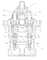
図3、図4に示すように、作業操作レバー7はバルブケース54の上部にジョイント56を介して前後左右回動自在に取り付けられている。作業操作レバー7の下端には円板状のカム57が固定され、該カム57の下面は左リモコンバルブ52に収納された、旋回用の左右一対のパイロットバルブ55L・55Rのプッシュロッド59・59と、アーム用の前後一対のパイロットバルブのプッシュロッド(図示せず)の上端と当接するように配設される。
As shown in FIGS. 3 and 4, the
前記プッシュロッド59・59は、上端がバルブケース54の上面よりも上方に突出され、下端はバネ座60・60の上面に当接されている。該バネ座60・60はスプール58・58の上端に嵌合され、該スプール58・58はバルブケース54に上下方向に形成されたバルブ孔に収納されている。前記各スプール58にはバネ91・92が外嵌され、バネ91はバネ座60とバルブケース54の間に介装されて、バネ座60及びプッシュロッド59を上方へ摺動するように付勢し、バネ92はバネ座60とスプール58の間に介装されて、スプール58を下方へ摺動するように付勢している。前記バネ91・91の付勢力により、作業操作レバー7は中立位置(前後左右中央)に保持される。
The
そして、一方の旋回方向(本実施形態では左側)の前記プッシュロッド59に回動制限付与手段90が取り付けられる。つまり、草刈作業機は一方向(左方向)へ刈取作業ができ、逆方向へは刈取できない構成となっているため、左方向に旋回させながら刈取作業をするように、左旋回操作用のスプール58に連係されるプッシュロッド59上に回動制限付与手段90が設けられる。但し、左右両方向に作業ができる形式の草刈機であれば、右側のプッシュロッド59にも回動制限付与手段90が取り付けられる。
Then, a rotation restriction imparting means 90 is attached to the
前記回動制限付与手段90の第一実施形態では、図3に示すように、円筒状に形成されてプッシュロッド59に外嵌でき、着脱可能に取り付けられる。回動制限付与手段90の軸心方向(上下方向)長さは、プッシュロッド59がバルブケース54の上面よりも突出している長さよりも短く構成している。
In the first embodiment of the rotation restriction imparting means 90, as shown in FIG. 3, it is formed in a cylindrical shape, can be externally fitted to the
こうして、作業操作レバー7を左旋回操作したときは、設定角度回動すると、回動途中でカム57が回動制限付与手段90と当接し、それ以上回動できず、旋回速度もそれ以上速くならないようにする。この当接位置(設定回動角度)、つまり、作業操作レバー7の回動が制限される位置(角度)は、作動油圧が上昇してリリーフする位置である。具体的には、外部油圧作業機16による草刈作業時に旋回操作したときに、外部油圧作業機16による作業が維持でき旋回速度が制限される位置である。つまり、外部油圧作業機16による作業時に旋回しても作業が十分できる作動油量が得られる位置である。言い換えれば、旋回操作しても草刈作業機の回転数が、草の絡みが生じる設定回転数以下とならない位置である。
In this way, when the
この設定回転数は、軸心方向長さの異なる回動制限付与手段90を作成して付け替えることにより変更可能である。つまり、外部油圧作業機16の種類(作業に必要な作動油量)に合わせて回動制限付与手段90を変更することにより所定の回転数で作業しながら旋回することができる。回動制限付与手段90の構造としては、円筒状として、作業操作レバー7を外してプッシュロッド59外周に着脱できるようにするのである。または、断面視略C字状の筒状に構成してプッシュロッド59側方より着脱可能に構成する。
This set rotational speed can be changed by creating and replacing the rotation restriction imparting means 90 having different axial lengths. That is, it is possible to turn while working at a predetermined number of revolutions by changing the rotation restriction imparting means 90 according to the type of the external hydraulic working machine 16 (the amount of hydraulic oil necessary for the work). As a structure of the rotation restriction imparting means 90, it is cylindrical and the
また、前記回動制限付与手段90の材質は、硬質の金属や合成樹脂により構成することで、作業操作レバー7の回動可能範囲は設定角度までとすることができ、作業回転数の低下を確実に防止することができる。
また、前記回動制限付与手段90の材質を弾性体で構成することもできる。例えば、回動制限付与手段90は、第二実施形態として、図4に示すように、弾性体として円筒状のゴム、または、図5に示すように、弾性体としてコイルバネ等で構成することができる。このような構成とすることで、外部油圧作業機16による作業時に、旋回するために作業操作レバー7を回動操作して、設定角度に達すると、カム57の下面が回動制限付与手段90の上面と当接して回動抵抗が増加し、手の感覚で前記設定角度に達したことを認識できるようになる。この回動位置以上回動すると油圧が高くなり、リリーフする可能性が高くなる。また、作業時以外等でさらに旋回速度を増加したい場合には、更に力を加えて回動することで弾性体を変形させて旋回速度を増加することが可能となる。
In addition, the material of the rotation restriction applying means 90 is made of hard metal or synthetic resin, so that the rotation range of the
Moreover, the material of the said rotation restriction provision means 90 can also be comprised with an elastic body. For example, as shown in FIG. 4, the rotation restriction imparting means 90 may be formed of a cylindrical rubber as an elastic body, or a coil spring as an elastic body as shown in FIG. it can. With such a configuration, when the work
また、前記回動制限付与手段90は、カム57と当接する代わりに、作業操作レバー7と当接する構成とすることも可能である。即ち、回動制限付与手段90の第三実施形態として、図6に示すように、回動制限付与手段90は板バネで構成して、下端をバルブケース54にボルト等により固定して上方へ延設し、該回動制限付与手段90の上端位置を、作業操作レバー7が設定角度回動したときに当接する位置とするのである。こうして、作業操作レバー7を回動操作すると、途中で回動制限付与手段90に当接し、回動抵抗が増加して設定角度回動したことが容易に認識できるのである。
Further, the rotation
また、前記回動制限付与手段90を設ける代わりにデテント機構95を構成することも可能である。即ち、回動制限付与手段90の第四実施形態として、図7に示すように、カム57のプッシュロッド59との当接面における設定回動角度位置に凹部(または、凸部、または、段差部)57aを形成して、作業操作レバー7を設定角度まで回動すると、プッシュロッド59の上端が凹部57aに嵌入して、軽く保持されるようにするのである。こうして、前記同様に、作業操作レバー7の回動操作途中で設定角度に達したことが容易に認識でき、作業が停止することを容易に避けることができる。但し、デテント機構95の配置位置はカム57に限定するものではなく、ジョイント56に設けることも可能である。
Also, a
前記回動制限付与手段90は本実施形態では、旋回操作用のリモコンバルブ52に設けたが、作業形態に合わせて、ブーム操作用のリモコンバルブやアーム操作用のリモコンバルブやバケット操作用のリモコンバルブに設けることも可能である。
In the present embodiment, the rotation restriction imparting means 90 is provided on the
以上のように、傾倒操作される作業操作レバー7の基部にカム57が設けられ、該カム57に左リモコンバルブ52の制御弁となるパイロットバルブのスプール58の一端に連結されるプッシュロッド59の先端が当接され、該プッシュロッド59の近傍に作業操作レバー7の回動を設定角度から制限する回動制限付与手段90が着脱可能に設けられるので、外部油圧作業機16と旋回を同時に作動させたときに、旋回操作する作業操作レバー7の操作角度を回動制限付与手段90により制限して、外部油圧作業機16の作動が停止すること未然に防止できる。また、回動制限付与手段90は外部油圧作業機16を使用しないときには外すことができ、外部油圧作業機16に合わせて付け替えることもでき、安価で簡単に操作制限することができる。
As described above, the
また、前記回動制限付与手段90による制限開始位置は、旋回モータ62を作動しつつ外部油圧作業機16を作動させる流量に分流できる位置とするので、外部油圧作業機16により作業しながら旋回ができて、外部油圧作業機16を停止させず、負荷の増大もなく、確実に作業が行える。
Further, the restriction start position by the rotation restriction applying means 90 is a position where the flow can be diverted to the flow rate for operating the external hydraulic working
前記回動制限付与手段90はプッシュロッド59の外周に配置されて弾性体で構成されるので、更に旋回速度を上げたいときには、弾性体を変形させる力を作業操作レバー7に加えることで実現でき、外部油圧作業機16の作業状態に合わせて旋回速度を変更できる。
The rotation restriction applying means 90 is arranged on the outer periphery of the
また、前記回動制限付与手段90はコイルバネで構成されるので、回動制限付与手段90は安価で容易に入手でき、着脱も簡単に行える。また、耐久性があり安定して操作制限ができる。 Further, since the rotation restriction applying means 90 is constituted by a coil spring, the rotation restriction applying means 90 can be easily obtained at low cost and can be easily attached and detached. In addition, it is durable and can be stably controlled.
7 作業操作レバー
16 外部油圧作業機
36 PTOコントロールバルブ
46 ロードチェックバルブ
52 左リモコンバルブ
57 カム
58 スプール
59 プッシュロッド
62 旋回油圧モータ
65 PTO油圧モータ
90 回動制限付与手段
7
Claims (4)
Priority Applications (1)
| Application Number | Priority Date | Filing Date | Title |
|---|---|---|---|
| JP2015127317A JP2017009082A (en) | 2015-06-25 | 2015-06-25 | Hydraulic operation device |
Applications Claiming Priority (1)
| Application Number | Priority Date | Filing Date | Title |
|---|---|---|---|
| JP2015127317A JP2017009082A (en) | 2015-06-25 | 2015-06-25 | Hydraulic operation device |
Publications (1)
| Publication Number | Publication Date |
|---|---|
| JP2017009082A true JP2017009082A (en) | 2017-01-12 |
Family
ID=57761347
Family Applications (1)
| Application Number | Title | Priority Date | Filing Date |
|---|---|---|---|
| JP2015127317A Pending JP2017009082A (en) | 2015-06-25 | 2015-06-25 | Hydraulic operation device |
Country Status (1)
| Country | Link |
|---|---|
| JP (1) | JP2017009082A (en) |
Cited By (1)
| Publication number | Priority date | Publication date | Assignee | Title |
|---|---|---|---|---|
| CN106380891A (en) * | 2015-07-25 | 2017-02-08 | 大连理工大学 | 4-hydroxyquinoline heterocyclic azo disperse dye and preparation method thereof |
Citations (18)
| Publication number | Priority date | Publication date | Assignee | Title |
|---|---|---|---|---|
| JPH0270836A (en) * | 1988-09-06 | 1990-03-09 | Hitachi Constr Mach Co Ltd | Control lever device |
| JPH02140005U (en) * | 1989-04-28 | 1990-11-22 | ||
| JPH04129989U (en) * | 1991-05-22 | 1992-11-30 | 株式会社小松製作所 | hydraulic pilot valve |
| JPH0518403A (en) * | 1991-07-12 | 1993-01-26 | Hitachi Constr Mach Co Ltd | Control device for working machine |
| JPH05287777A (en) * | 1992-04-07 | 1993-11-02 | Yutani Heavy Ind Ltd | Hydraulic circuit of construction machinery |
| JPH0581510U (en) * | 1992-04-08 | 1993-11-05 | 株式会社小松製作所 | Hydraulic pilot valve |
| JPH08188399A (en) * | 1994-12-28 | 1996-07-23 | Toyota Autom Loom Works Ltd | Hydraulic circuit for high lift work vehicle |
| JP2000145711A (en) * | 1998-11-10 | 2000-05-26 | Uchida Hydraulics Co Ltd | Method and device for controlling turning system hydraulic device |
| JP2002501246A (en) * | 1998-01-22 | 2002-01-15 | マンネマン レクスロス ソシエテ アノニム | Remote controls, especially hydraulic manipulators |
| JP2002156070A (en) * | 2000-11-17 | 2002-05-31 | Kawasaki Heavy Ind Ltd | Hydraulic operation valve |
| JP2003013911A (en) * | 2001-06-28 | 2003-01-15 | Komatsu Ltd | Monolever operation device |
| US20030111120A1 (en) * | 2001-12-14 | 2003-06-19 | Aarestad Robert A. | Magnetic detent assist assembly |
| JP2004036663A (en) * | 2002-06-28 | 2004-02-05 | Sumitomo Heavy Industries Construction Crane Co Ltd | Hydraulic control valve |
| JP2006504916A (en) * | 2002-10-31 | 2006-02-09 | ボツシュ レックスロス ディ.エス.アイ. | Pressurized fluid distributor |
| JP2010152617A (en) * | 2008-12-25 | 2010-07-08 | Kubota Corp | Operation lever device |
| JP2010210071A (en) * | 2009-03-12 | 2010-09-24 | Komatsu Ltd | Operating lever device |
| JP2011111796A (en) * | 2009-11-26 | 2011-06-09 | Caterpillar Sarl | Turning hydraulic control device for working machine |
| JP2012198587A (en) * | 2011-03-18 | 2012-10-18 | Kawasaki Heavy Ind Ltd | Operation device |
-
2015
- 2015-06-25 JP JP2015127317A patent/JP2017009082A/en active Pending
Patent Citations (18)
| Publication number | Priority date | Publication date | Assignee | Title |
|---|---|---|---|---|
| JPH0270836A (en) * | 1988-09-06 | 1990-03-09 | Hitachi Constr Mach Co Ltd | Control lever device |
| JPH02140005U (en) * | 1989-04-28 | 1990-11-22 | ||
| JPH04129989U (en) * | 1991-05-22 | 1992-11-30 | 株式会社小松製作所 | hydraulic pilot valve |
| JPH0518403A (en) * | 1991-07-12 | 1993-01-26 | Hitachi Constr Mach Co Ltd | Control device for working machine |
| JPH05287777A (en) * | 1992-04-07 | 1993-11-02 | Yutani Heavy Ind Ltd | Hydraulic circuit of construction machinery |
| JPH0581510U (en) * | 1992-04-08 | 1993-11-05 | 株式会社小松製作所 | Hydraulic pilot valve |
| JPH08188399A (en) * | 1994-12-28 | 1996-07-23 | Toyota Autom Loom Works Ltd | Hydraulic circuit for high lift work vehicle |
| JP2002501246A (en) * | 1998-01-22 | 2002-01-15 | マンネマン レクスロス ソシエテ アノニム | Remote controls, especially hydraulic manipulators |
| JP2000145711A (en) * | 1998-11-10 | 2000-05-26 | Uchida Hydraulics Co Ltd | Method and device for controlling turning system hydraulic device |
| JP2002156070A (en) * | 2000-11-17 | 2002-05-31 | Kawasaki Heavy Ind Ltd | Hydraulic operation valve |
| JP2003013911A (en) * | 2001-06-28 | 2003-01-15 | Komatsu Ltd | Monolever operation device |
| US20030111120A1 (en) * | 2001-12-14 | 2003-06-19 | Aarestad Robert A. | Magnetic detent assist assembly |
| JP2004036663A (en) * | 2002-06-28 | 2004-02-05 | Sumitomo Heavy Industries Construction Crane Co Ltd | Hydraulic control valve |
| JP2006504916A (en) * | 2002-10-31 | 2006-02-09 | ボツシュ レックスロス ディ.エス.アイ. | Pressurized fluid distributor |
| JP2010152617A (en) * | 2008-12-25 | 2010-07-08 | Kubota Corp | Operation lever device |
| JP2010210071A (en) * | 2009-03-12 | 2010-09-24 | Komatsu Ltd | Operating lever device |
| JP2011111796A (en) * | 2009-11-26 | 2011-06-09 | Caterpillar Sarl | Turning hydraulic control device for working machine |
| JP2012198587A (en) * | 2011-03-18 | 2012-10-18 | Kawasaki Heavy Ind Ltd | Operation device |
Cited By (1)
| Publication number | Priority date | Publication date | Assignee | Title |
|---|---|---|---|---|
| CN106380891A (en) * | 2015-07-25 | 2017-02-08 | 大连理工大学 | 4-hydroxyquinoline heterocyclic azo disperse dye and preparation method thereof |
Similar Documents
| Publication | Publication Date | Title |
|---|---|---|
| JP6569852B2 (en) | Hydraulic device | |
| US7874377B1 (en) | Circle drive arrangement for motor grader | |
| WO2017173338A1 (en) | Variable engine speed control | |
| JP2012229802A (en) | Fluid circuit, and working machine including the same | |
| JP2001020907A (en) | Operation lever device | |
| US10641388B2 (en) | Hydraulic system of work machine and work machine | |
| JP2017009082A (en) | Hydraulic operation device | |
| JP2012031753A (en) | Hydraulic driving device for construction machine | |
| JP2016053375A5 (en) | ||
| JP7071198B2 (en) | Hydraulic circuit of work vehicle | |
| JP6286216B2 (en) | Work machine control system and low pressure selection circuit | |
| JP7049213B2 (en) | Hydraulic circuit of construction machinery | |
| JP2018105487A (en) | Hydraulic actuation device | |
| JP2015231813A (en) | Crawler type running vehicle | |
| JP6723896B2 (en) | Hydraulic traveling device | |
| JP6936687B2 (en) | Work vehicle | |
| KR20210131319A (en) | Traction Control of Steering Articulated Power Machines | |
| JP6026143B2 (en) | Swivel work machine | |
| JP4916178B2 (en) | Travel control device for work machine | |
| JP6944025B2 (en) | Work vehicle | |
| JP6964059B2 (en) | Construction machinery | |
| WO2021124767A1 (en) | Hydraulic circuit for construction machine | |
| JPH10331210A (en) | Hydraulic circuit for service car | |
| JP2017187076A (en) | Hydraulic circuit of hydraulic work machine | |
| JP2836501B2 (en) | Tractor turning operation device |
Legal Events
| Date | Code | Title | Description |
|---|---|---|---|
| A621 | Written request for application examination |
Free format text: JAPANESE INTERMEDIATE CODE: A621 Effective date: 20180122 |
|
| A977 | Report on retrieval |
Free format text: JAPANESE INTERMEDIATE CODE: A971007 Effective date: 20181214 |
|
| A131 | Notification of reasons for refusal |
Free format text: JAPANESE INTERMEDIATE CODE: A131 Effective date: 20190115 |
|
| A02 | Decision of refusal |
Free format text: JAPANESE INTERMEDIATE CODE: A02 Effective date: 20190709 |