JP2017008567A - Safety construction stair - Google Patents
Safety construction stair Download PDFInfo
- Publication number
- JP2017008567A JP2017008567A JP2015124372A JP2015124372A JP2017008567A JP 2017008567 A JP2017008567 A JP 2017008567A JP 2015124372 A JP2015124372 A JP 2015124372A JP 2015124372 A JP2015124372 A JP 2015124372A JP 2017008567 A JP2017008567 A JP 2017008567A
- Authority
- JP
- Japan
- Prior art keywords
- plate
- decorative
- base
- board
- rear end
- Prior art date
- Legal status (The legal status is an assumption and is not a legal conclusion. Google has not performed a legal analysis and makes no representation as to the accuracy of the status listed.)
- Granted
Links
Images


Abstract
Description
この発明は、仕上げ前の仮設状態で建築作業用の仮設階段として利用することができる安全施工階段に関する。 The present invention relates to a safe construction stair that can be used as a temporary stair for building work in a temporary state before finishing.
特許文献1に示すように従来より一般的な木質製の屋内階段は、水平な段板と、垂直なけこみ板とが交互に配置されて構成されている。このような屋内階段は建築作業中に使用されることなく、作業者は建築現場に組み立てられた仮設足場の階段(仮設階段)等を利用して、階下や階上への行き来を行うようにしている。
As shown in
一方近年において、戸建て住宅を建築するに際して、仕上げ前の仮設状態で建築作業用の仮設階段として利用し、最終的に当該仮設階段に対し仕上げ施工を行って組立を完了し、居住者用の屋内階段として用いることができる安全施工階段が周知である。 On the other hand, in recent years, when building a detached house, it is used as a temporary staircase for building work in a temporary state before finishing, and finally the temporary staircase is finished to complete the assembly. Safety construction stairs that can be used as stairs are well known.
例えば下記特許文献2,3に示す安全施工階段においては、段板が下地段板と、下地段板の上面(表面)に貼り付けられる化粧段板とで構成されている。そして建築中には、下地段板に化粧段板を貼り付ける前の仮設状態としておき、その仮設状態の階段を建築作業用の仮設階段(仮設足場)として使用するようにしている。さらに所定の建築作業が完了した後、仮設状態の階段における下地段板の上面に化粧段板を貼り付けて組立を完了し、通常の屋内階段に仕上げるようにしている。
For example, in the safe construction stairs shown in
上記特許文献2,3に示す安全施工階段において、下地段板の両側端部は、側板等によって下側から支持されるとともに、前端側は、下位のけこみ板によって下側から支持されている。しかしながら、下地段板の後端側は上位のけこみ板の下部前面に対向して配置されており、下側から支持されていない。このため例えば、下地段板に高荷重が加わった際等に、下地段板の後端側の中央部が沈み込むような有害なたわみ変形が生じるおそれがあった。
In the safety construction stairs shown in
一方、下地段板をその板厚を厚くして強度を高めることによって、上記のたわみ変形を防止することはできるが、そうすると、板厚の増大に伴って、材料費が高騰してコストの増大を来すとともに、重量が増加して下地段板の取扱作業が困難になり、組立作業性の低下を来すという新たな課題が発生する。 On the other hand, it is possible to prevent the above-mentioned bending deformation by increasing the thickness by increasing the thickness of the base plate, but if so, the material cost increases as the plate thickness increases and the cost increases. In addition, a new problem arises in that the weight increases and the handling work of the base plate becomes difficult and the assembly workability deteriorates.
この発明は、上記の課題に鑑みてなされたものであり、仕上げ前の仮設状態で作業階段として利用できる上さらに、コストの削減および組立作業性の向上を図りつつ、下地段板の後端も下側から支持できて、下地段板に有害なたわみ変形が生じるのを防止することができる安全施工階段を提供することを目的とする。 The present invention has been made in view of the above problems, and can be used as a work staircase in a temporary state before finishing.In addition, the rear end of the base plate is also reduced while reducing costs and improving assembly workability. An object of the present invention is to provide a safe construction stair that can be supported from the lower side and can prevent the occurrence of harmful deflection deformation in the base step board.
上記課題を解決するため、本発明は、以下の手段を備えるものである。 In order to solve the above problems, the present invention comprises the following means.
[1]斜め方向に間隔をおいて配置される複数の下地段板を備え、隣り合う前記下地段板間に配置されるけこみ板の上端が上側の下地段板の前部下面に対応して配置されるとともに、当該けこみ板の前面下端部が下側の下地段板の後端に対応して配置された仮設状態に対し、前記下地段板の上面に化粧段板が貼り付けられて仕上げ状態となる安全施工階段であって、
前記けこみ板の前面下端部に、前記下地段板の後端に対応して段板挿入溝が形成されるとともに、その段板挿入溝に前記下地段板の後端が挿入された状態に配置されていることを特徴とする安全施工階段。
[1] Provided with a plurality of base plate arranged at intervals in an oblique direction, the upper end of the squeeze plate arranged between the adjacent base plate corresponding to the front lower surface of the upper base plate For the temporary state where the front lower end portion of the rake plate is arranged corresponding to the rear end of the lower base step plate, a decorative step plate is attached to the upper surface of the base step plate. It is a safe construction stair that will be in a finished state
A step plate insertion groove corresponding to the rear end of the base step plate is formed in the front lower end portion of the scraping plate, and the rear end of the base step plate is inserted into the step plate insertion groove. Safe construction stairs characterized by being arranged.
[2]前記段板挿入溝の下側が、前記下地段板を挿入する下地段板挿入部として構成され、
前記段板挿入溝における前記下地段板の上面と前記段板挿入溝の内周上側面との間の隙間が化粧段板挿入部として構成され、
仕上げ状態では前記化粧段板の後端が前記化粧段板挿入部に挿入された状態に配置されている前項1に記載の安全施工階段。
[2] The lower side of the step plate insertion groove is configured as a base step plate insertion portion for inserting the base step plate,
A gap between the upper surface of the base plate in the step plate insertion groove and the inner peripheral upper side surface of the step plate insertion groove is configured as a decorative step plate insertion portion,
The safe construction staircase according to the preceding
[3]前記化粧段板の上面後端が前記段板挿入溝の内周上側面に圧接した状態に配置されている前項2に記載の安全施工階段。 [3] The safe construction staircase according to the above item 2, wherein the upper rear end of the decorative step board is disposed in pressure contact with the inner peripheral upper side surface of the step board insertion groove.
[4]前記化粧段板の厚さが前記化粧段板挿入部よりも厚く形成され、その化粧段板挿入部に前記化粧段板の後端が圧縮した状態に挿入されている前項2または3に記載の安全施工階段。
[4] The preceding
[5]前記下地段板および前記化粧段板間に介在された接着剤が膨張することによって、前記化粧段板の上面後端が前記段板挿入溝の内周上側面に圧接するように構成されている前項2〜4のいずれか1項に記載の安全施工階段。 [5] A configuration in which an adhesive interposed between the base plate and the decorative plate expands so that an upper surface rear end of the decorative plate is pressed against an inner peripheral upper surface of the step plate insertion groove. 5. The safe construction staircase according to any one of items 2 to 4 above.
[6]前記下地段板の上面後端に下地段板切欠凹部が形成されるとともに、
その下地段板切欠凹部の前端位置が上位のけこみ板の前面よりも前方に配置されている前項2〜5のいずれか1項に記載の安全施工階段。
[6] A base plate notch recess is formed at the rear end of the top surface of the base plate,
6. The safe construction staircase according to any one of the preceding items 2 to 5, wherein the front end position of the base step plate notch recess is disposed in front of the front surface of the upper indenting plate.
[7]前記化粧段板の下面後端に化粧段板切欠凹部が形成されることにより、前記化粧段板の後端縁が薄く形成されている前項2〜6のいずれか1項に記載の安全施工階段。 [7] The item described in any one of the above items 2 to 6, wherein a rear edge of the decorative step board is formed thin by forming a notch recess in the lower face of the lower surface of the decorative step board. Safety construction stairs.
[8]前記下地段板挿入部の奥行きが前記化粧段板挿入部の奥行きよりも深く形成されている前項2〜7のいずれか1項に記載の安全施工階段。 [8] The safe construction staircase according to any one of items 2 to 7, wherein a depth of the base step board insertion portion is deeper than a depth of the decorative step board insertion portion.
[9]前記下地段板の厚さが前記下地段板挿入部よりも厚く形成され、その下地段板挿入部に前記下地段板の後端が圧縮した状態に挿入されている前項2〜8のいずれか1項に記載の安全施工階段。 [9] The items 2 to 8 above, wherein the thickness of the base step plate is thicker than that of the base step plate insertion portion, and the rear end of the base step plate is inserted into the base step plate insertion portion in a compressed state. The safe construction staircase according to any one of the above.
[10]前記下地段板の後端面下縁部に下地段板側面取り部が形成されている前項1〜9のいずれか1項に記載の安全施工階段。
[10] The safety construction stair according to any one of the preceding
[11]前記けこみ板における段板挿入溝の開口縁部下側にけこみ板側面取り部が形成されている前項1〜10のいずれか1項に記載の安全施工階段。
[11] The safety construction stair according to any one of the preceding
[12]仮設状態では前記けこみ板の前面に剥離可能な養生材が積層されるとともに、
仕上げ状態では前記養生材が前記けこみ板から取り外されている前項1〜11のいずれか1項に記載の安全施工階段。
[12] In the temporary state, a peelable curing material is laminated on the front surface of the rake plate,
The safe construction staircase according to any one of the preceding
[13]前記けこみ板の前面に貼り付け可能なけこみ板化粧材が設けられ、
仮設状態において前記けこみ板は前記けこみ板化粧材が取り外された状態であり、仕上げ状態では前記けこみ板にけこみ板化粧材が貼り付けられている前項1〜11のいずれか1項に記載の安全施工階段。
[13] A decorative board decorative material that can be attached to the front surface of the electronic board is provided,
In any one of the preceding
[14]前記下地段板および前記化粧段板の前端部を覆う段鼻が設けられている前項1〜13のいずれか1項に記載の安全施工階段。
[14] The safety construction staircase according to any one of
[15]前記段鼻が前記化粧段板に一体に形成されている前項14に記載の安全施工階段。
[15] The safe construction staircase according to the
[16]前記化粧段板の前端面に雄ざね部が形成されるとともに、前記段鼻の裏面側に雌ざね部が形成され、
前記雄ざね部が前記雌ざね部に嵌め込まれて、前記段鼻が前記化粧段板に取り付けられている前項14に記載の安全施工階段。
[16] A male ridge is formed on the front end surface of the decorative corrugated board, and a female ridge is formed on the back side of the nose,
15. The safe construction staircase according to
[17]前記段板挿入溝のうち、化粧段板を挿入するための化粧段板挿入部に化粧段板によって圧縮変形するクッション材を配置し、そのクッション材の復元力によって前記化粧段板が前方へ押し込まれて、前記化粧段板の前端が前記段鼻に圧接するように構成されている前項16に記載の安全施工階段。 [17] A cushioning material that is compressed and deformed by the decorative stepboard is disposed in the decorative stepboard insertion portion for inserting the decorative stepboard in the stepboard insertion groove, and the decorative stepboard is restored by the restoring force of the cushioning material. The safe construction staircase according to the preceding item 16, wherein the staircase is pushed forward and the front end of the decorative step board is pressed against the nose.
[18]前記下地段板の側縁部および前記けこみ板の側縁部を支持する側板を備え、
前記側板の上端縁に、前記下地段板の両側下面を支持する水平な段板取付部と、前記けこみ板の両側下端を支持する垂直なけこみ板取付部とが交互に設けられ、
前記側板における前記段板取付部の後端に前記けこみ板の下端を挿入配置するためのけこみ板挿入用切欠部が形成されている前項1〜17のいずれか1項に記載の安全施工階段。
[18] A side plate that supports a side edge of the base plate and a side edge of the rake plate,
On the upper edge of the side plate, horizontal step plate mounting portions that support the lower surfaces of both sides of the base step plate, and vertical scoop plate mounting portions that support the bottom ends of both sides of the scoring plate are alternately provided,
18. The safety construction according to any one of the preceding
発明[1]の安全施工階段によれば、下地段板の後端を上位のけこみ板の段板挿入溝によって下側から支持することができるため、下地段板の後端が沈み込むような有害なたわみ変形が生じるのを確実に防止することができる。また下地段板として薄くて軽量のものを使用できるため、薄板化により材料費を削減できるとともに、軽量化により下地段板の取扱作業を容易に行えて、組立作業性を向上させることができる。さらに下地段板を段板挿入溝に挿入するだけで簡単に、下地段板の位置決めを図ることができるため、組立作業性を一層向上させることができる。 According to the safe construction staircase of the invention [1], the rear end of the base step board can be supported from the lower side by the step board insertion groove of the upper indenting board, so that the rear end of the base step board sinks. Thus, it is possible to reliably prevent the occurrence of harmful and harmful deflection deformation. Further, since a thin and lightweight base plate can be used, the material cost can be reduced by reducing the thickness, and the handling work of the base plate can be easily performed by reducing the weight, thereby improving the assembly workability. Further, since the base plate can be easily positioned by simply inserting the base plate into the plate plate insertion groove, the assembling workability can be further improved.
発明[2]の安全施工階段によれば、化粧段板の後端をけこみ板の段板挿入溝に挿入しているため、化粧段板の後端の収まり具合が良くなり、良好な美観を得ることができる。 According to the safe construction staircase of the invention [2], the rear end of the decorative step board is inserted into the step plate insertion groove of the scooping plate, so that the fit of the rear end of the decorative step board is improved, and a good aesthetic appearance is obtained. Can be obtained.
発明[3]〜[5]の安全施工階段によれば、段板挿入溝の上側開口縁部に隙間が形成されるのを防止でき、良好な美観をより確実に得ることができる。 According to the safe construction steps of inventions [3] to [5], it is possible to prevent a gap from being formed at the upper opening edge of the step plate insertion groove, and it is possible to more reliably obtain a good aesthetic appearance.
発明[6][7]の安全施工階段によれば、化粧段板挿入部の巾が狭くとも、その化粧段板挿入部に化粧段板を確実に差し込むことができる。 According to the safe construction steps of the inventions [6] and [7], even if the width of the decorative step board insertion portion is narrow, the decorative step plate can be reliably inserted into the decorative step plate insertion portion.
発明[8]の安全施工階段によれば、下地段板を下地段板挿入部に挿入した際に、下地段板の上方向の位置決めも図ることができるため、組立作業性をより向上させることができる。 According to the safe construction stairs of the invention [8], when the base step board is inserted into the base step board insertion portion, the base step board can be positioned in the upward direction, so that the assembly workability is further improved. Can do.
発明[9]の安全施工階段によれば、下地段板を下地段板挿入部に強固にかつ安定状態に嵌め込むことができ、下地段板の位置ずれ等を確実に防止することができる。 According to the safe construction staircase of the invention [9], the base step plate can be firmly and stably fitted into the base step plate insertion portion, and the misalignment of the base step plate can be reliably prevented.
発明[10][11]の安全施工階段によれば、下地段板を段板挿入溝に確実に差し込むことができる。 According to the safe construction steps of the inventions [10] and [11], the base step plate can be reliably inserted into the step plate insertion groove.
発明[12][13]の安全施工階段によれば、仕上げ状態でけこみ板に確実に化粧を施すことができる。 According to the safe construction steps of the inventions [12] and [13], makeup can be reliably applied to the kink plate in the finished state.
発明[14]〜[16]の安全施工階段によれば、下地段板および化粧段板の前端に段鼻を確実に取り付けることができる。 According to the safe construction steps of the inventions [14] to [16], the nose can be securely attached to the front ends of the base plate and the decorative plate.
発明[17]の安全施工階段によれば、化粧段板を安定した状態に取り付けることができる。 According to the safe construction staircase of the invention [17], the decorative step board can be attached in a stable state.
発明[18]の安全施工階段によれば、けこみ板を側板のけこみ板挿入用切欠部内に挿入した際に、けこみ板の側板に対する位置決めを図ることができるため、けこみ板を所定の組付位置に精度良く簡単に配置できて組付作業性をより一層向上させることができる。 According to the safe construction staircase of the invention [18], when the squeeze plate is inserted into the squeeze plate insertion notch of the side plate, the squeeze plate can be positioned with respect to the side plate. Therefore, the assembly workability can be further improved.
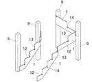
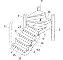
図1A〜図1Dはこの発明の実施形態である安全施工階段が適用されたひな壇階段の構成を説明するための斜視図である。なお本実施形態においては、階段を下りる際に使用者が向いている方向を「前側」とし、階段を上る際に使用者が向いている方向を「後側」として説明する。また図1A〜図1Dに示す階段は、下側が直階段によって構成され、上側が回り階段によって構成されているが、以下の説明においては発明の理解を容易にするため、直階段の部分に本発明を適用する場合を例に挙げて説明する。もっとも本発明は、直階段に限られず、回り階段にも適用することができる。 FIG. 1A to FIG. 1D are perspective views for explaining the structure of a doll platform staircase to which a safe construction staircase according to an embodiment of the present invention is applied. In the present embodiment, the direction in which the user is facing when going down the stairs is referred to as “front side”, and the direction in which the user is facing when going up the stairs is described as “rear side”. 1A to 1D, the lower side is constituted by a straight staircase and the upper side is constituted by a rotating staircase. However, in the following description, in order to facilitate the understanding of the invention, the straight staircase portion is provided with a main staircase. The case where the invention is applied will be described as an example. However, the present invention is not limited to a straight staircase but can be applied to a rotating staircase.
図1Aに示すように家屋構造材としての支柱9に、一対のひな壇用側板(両側板)1,1が固定されて、この両側板1,1が階段施工領域の両側に沿って斜めに配置される。言うまでもなく側板1は、支柱9だけに限られず、壁面等の他の構造材に支持するようにしても良い。
As shown in FIG. 1A, a pair of side plates (both side plates) 1, 1 are fixed to a
さらに図1Bに示すように両側板1,1に複数のけこみ板3が斜め方向に適宜間隔をおいて垂直配置に取り付けられる。後に説明するが、けこみ板3の表面(前面)には透明な養生フィルムが貼り付けられている。
Further, as shown in FIG. 1B, a plurality of squeezing
また図1Cに示すように両側板1,1における隣り合うけこみ板2間に複数の下地段板21が斜め方向に適宜間隔をおいて水平配置に取り付けられる。この状態を本実施形態においては仮設状態と称し、隣り合う下地段板21間に配置されるけこみ板2の上端が上側の下地段板21の前部下面に対応して配置されるとともに、当該けこみ板2の前面下端部が下側の下地段板21の後端に対応して配置されている。そして本実施形態においてはこの仮設状態の階段(仮設階段)が建築作業用の作業階段として用いられる。例えばこの仮設階段を用いて内装工事等を行うものである。
Further, as shown in FIG. 1C, a plurality of
そして最終的には図1Dに示すように仮組階段における下地段板21上に化粧段板25が貼り付けられるとともに、けこみ板3に貼り付けられていた養生フィルムが剥ぎ取られる。こうして仕上げ状態となり、この仕上げ状態の階段(仕上げ階段)が居住者用の通常の屋内階段として用いられる。
And finally, as shown to FIG. 1D, while the
ここで本実施形態においては、所定の下地段板21の後端側(上側)および前端側(下側)に隣接する2つのけこみ板3のうち、後端側に隣接するけこみ板3を上位のけこみ板3と称し、前端側に隣接するけこみ板3を下位のけこみ板3と称することとする。また本実施形態において、単に段板と言う場合には、下地段板21および化粧段板25の双方を含む場合である。
Here, in the present embodiment, among the two
なお上記図1A〜図1Dは必ずしも施工手順と一致するものではなく、上位のけこみ板3を取り付ける作業と、そのけこみ板3の下部前側に下地段板21を取り付ける作業とを階下から階上に向かって交互に行って、けこみ板3および下地段板21を組み付けるのが最も一般的な施工手順である。さらに下地段板21に上位のけこみ板3を取り付けて、そのけこみ板付きの下地段板を階下から階上に向かって順次側板1に組み付けるような施工手順も多く採用されている。もっとも本発明においては、階段の施工手順は限定されるものではなく、どのような手順で組み立てても良いが、階段を上から順次組み付けていく場合に比べて、階段を下から順次組み付けて行く方が効率良くスムーズに階段を組み立てることができる。
1A to 1D are not necessarily consistent with the construction procedure, and the work of attaching the
以下、本実施形態のひな壇階段の構成について詳細に説明する。 Hereinafter, the configuration of the stepped stairs of this embodiment will be described in detail.
図1Aに示すようにひな壇階段の側板1は、所定の傾斜角度で斜め方向に延びるように配置されている。この側板1の上側縁部は階段状に切り欠かれることによって、水平な切り口と、垂直な切り口とが交互に並んで配置されるように形成されている。そして水平な切り口が段板取付用木口12として構成されるとともに、垂直な切り口がけこみ板取付用木口13として構成されている。
As shown in FIG. 1A, the
なお本実施形態においては、段板取付用木口12が段板取付部として構成されるとともに、けこみ板取付用木口13がけこみ板取付部として構成されている。
In this embodiment, the corrugated
側板1における段板取付用木口12の後端には、けこみ板取付用木口13に対応して上方に向けて開口するけこみ板挿入用切欠部14が形成されている。
At the rear end of the corrugated
本実施形態において側板1は、例えば18mm厚の合板等の木質系材料によって構成されている。
In the present embodiment, the
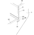
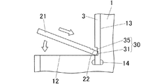
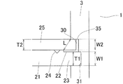
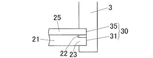
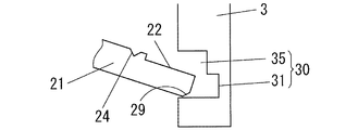
図2および図3に示すようにけこみ板3は、前面(表面)側の下部に階段巾方向(けこみ板長さ方向)に沿って段板挿入溝30が形成されている。この段板挿入溝30の下側には、下地段板21の後端差込部23を挿入配置するための下地段板挿入部31が設けられるとともに、上側には、化粧段板25の後端縁を挿入配置するための化粧段板挿入部35が設けられる。なお下地段板挿入部31および化粧段板挿入部35については後に詳述する。
As shown in FIG. 2 and FIG. 3, the
本実施形態においては、下地段板挿入部31の奥行き(深さ)が化粧段板挿入部35の奥行き(深さ)よりも深く形成されており、下地段板挿入部31の底面(後面)が化粧段板挿入部35の底面(後面)に対し後方に配置されるようになっている。
In the present embodiment, the depth (depth) of the base corrugated
本実施形態においてけこみ板3の材料としては、木質系材料を用いることができ、例えば12mm〜30mm厚の合板等を好適に用いることができる。本実施形態のけこみ板3の材料としては21mm厚の合板が採用されている。
In this embodiment, the material of the
またけこみ板3の前面(表面)におけるその少なくとも段板挿入溝30よりも上方の部分は化粧が施されており、その化粧部分には養生材として透明な養生フィルム(図示省略)が貼り付けられている。
In addition, at least a portion above the step
本実施形態においては、養生材として透明な養生フィルム(シート)を用いているが、それだけに限られず他の養生材を用いるようにしても良い。例えばフィルムやシートに限られることはなく、紙、テープ等によって構成された養生材を用いることもできる。さらに養生材としては、透明なものに限られることはなく、不透明ないし半透明で着色されたものも用いることができる。 In this embodiment, a transparent curing film (sheet) is used as a curing material, but the present invention is not limited to this, and other curing materials may be used. For example, it is not limited to a film or a sheet, and a curing material composed of paper, tape, or the like can be used. Further, the curing material is not limited to a transparent material, and an opaque or translucent colored material can also be used.
図1Bおよび図2に示すようにこの養生フィルム付きのけこみ板3を一対の側板1に組み付けるには、両側板1の各けこみ板取付用木口13に、けこみ板3における背面側(後面側)の両側縁部を沿わせるようにして、けこみ板3の下端部を両側板1のけこみ板挿入用切欠部14内に挿入配置し、その状態でけこみ板3を糊釘併用で固定する。すなわちけこみ板3の裏面側両側縁部と側板1のけこみ板取付用木口13との間に介在されるように接着剤を塗布しておき、けこみ板3の両側縁部に表面側からフィニッシュネイル等の釘(図示省略)を打ち込んでけこみ板取付用木口13に固定する。こうしてけこみ板3を側板1に固定する。
As shown in FIG. 1B and FIG. 2, in order to assemble the
ここで本実施形態においては、けこみ板3を側板1のけこみ板挿入用切欠部14内に挿入した際に、けこみ板3の側板1に対する位置決めを図ることができるため、けこみ板3を所定の組付位置に精度良く簡単に配置できて組付作業性を向上させることができる。
Here, in the present embodiment, when the
さらにけこみ板3をけこみ板挿入用切欠部14内に挿入配置した後は、けこみ板3はけこみ板挿入用切欠部14によって仮保持されて作業者が支持しなくとも取付姿勢を維持できるため、作業者は両手を自由に用いて釘打ち作業等のけこみ板3の固定作業を行うことができる。従ってけこみ板3の組付固定作業を簡単かつスムーズに行うことができ、組付作業性を一層向上させることができる。
Further, after the
なお、本実施形態においてけこみ板3が側板1に組み付けられた状態においては、けこみ板3の段板挿入溝30が側板1における段板取付用木口12の上方に対応して配置されている。
In the present embodiment, in a state where the
図3および図4に示すように下地段板21は、上面の後端縁に階段巾方向(段板長さ方向)に沿って連続し、かつ上方および後方に向けて開口する断面L字状の下地段板切欠凹段部22を有している。この下地段板切欠凹段部22の前端位置は、下地段板21を組み付けた状態においては、上位のけこみ板3の前面よりも前方に配置されるようになっている。後に詳述するが、この下地段板切欠凹段部22は、下地段板切欠凹部に相当するものであり、化粧段板25の化粧段板挿入部35への挿入操作を容易に行うためのものである。
As shown in FIG. 3 and FIG. 4, the
図8に示すようにこの下地段板21における下地段板切欠凹段部22が形成される部分、つまり下地段板21の後端差込部23の厚さT1は、けこみ板3における下地段板挿入部31の巾寸法(隙間寸法)W1よりも少し大きく(厚く)形成されている。
As shown in FIG. 8, the thickness T <b> 1 of the rear
また下地段板21の上面における下地段板切欠凹部22よりも少し前方には、階段巾方向(段板長さ方向)に沿って連続する断面V字状の釘打ち用溝24が形成されている。
In addition, a nailing
本実施形態において下地段板21の材料としては、木質系材料を用いることができ、例えば12mm〜30mm厚の合板等を好適に用いることができる。本実施形態の下地段板21の材料としては18mm厚の合板が採用されている。
In the present embodiment, as the material of the
図1Cおよび図4に示すようにこの下地段板21を一対の側板1等に組み付けるには、後端側が下向きとなるように下地段板21を斜め姿勢に配置した状態で、その下地段板21の後端差込部23を上位のけこみ板3の下地段板挿入部31に対向させ、続いて下地段板21をその後端差込部23を化粧段板挿入部31に挿入しながら水平姿勢となるように回転させる。これにより下地段板21における両側縁部が両側板1の各段板取付用木口12に沿った状態で、下地段板21の後端差込部23が上位のけこみ板3の下地段板挿入部31内に嵌め込まれる。そしてその状態で下地段板21を側板1およびけこみ板3に糊釘併用で固定する。すなわち下地段板21の下面側における前縁部、後縁部および両側縁部の全周(周囲4辺)と、それに対応する、下位のけこみ板3の上端面、上位のけこみ板3の下地段板挿入部31、および両側板1の段板取付用木口12との間にそれぞれ介在されるように接着剤を塗布しておく。さらに図5に示すように下地段板21の両側縁部に上方からフィニッシュネイル等の釘51を打ち込んで側板1の段板取付用木口12に固定し、下地段板21の前縁部に上方からフィニッシュネイル等の釘51を下側に隣接する下位のけこみ板3の上端面に固定するとともに、下地段板21の後縁部における釘打ち込み用溝24に斜め前方からフィニッシュネイル等の釘51を打ち込んで上位のけこみ板3における下地段板挿入部31に固定する。こうして下地段板21を側板1およびけこみ板3に糊釘併用で固定する。
As shown in FIG. 1C and FIG. 4, in order to assemble the
ここで本実施形態においては、下地段板21をけこみ板3の下地段板挿入部31に挿入した際に、下地段板21の側板1およびけこみ板3に対する位置決めを図ることができるため、下地段板21を所定の組付位置に精度良く簡単に配置できて組付作業性を向上させることができる。特に下地段板挿入部31の奥行きを化粧段板挿入部35の奥行きよりも深く形成しているため、下地段板21を下地段板挿入部31に挿入した際に上方向の位置決めも図ることができ、組付作業性を一層向上させることができる。
Here, in this embodiment, when the
また本実施形態においては既述した通り、下地段板21の後端差込部23の厚さT1をけこみ板3の下地段板挿入部31の巾(隙間)W1よりも少し大きく形成しているため、下地段板21の後端差込部23が弾性圧縮変形しながら下地段板挿入部31内に挿入される。このため上記の圧縮変形に対する復元力によって下地段板21をけこみ板3の下地段板挿入部31に強固にかつ安定状態に嵌め込むことができ、下地段板21の位置ずれ等を確実に防止することができる。
Further, in the present embodiment, as described above, the thickness T1 of the rear
また本実施形態においては、下地段板21の周囲4辺の全周を、側板1およびけこみ板3によって支持固定できるため、下地段板21に加わる荷重を周囲に均等に分散させて支持できて、下地段板21を安定した状態に確実に組み付けることができる。特に下地段板21の後端縁を上位のけこみ板3の下地段板挿入部31によって下側から支持できるため、下地段板21に高荷重が加わった際に下地段板21の後端部中央が沈み込むような有害なたわみ変形が生じるのを確実に防止することができる。
Further, in this embodiment, since the entire circumference of the four sides of the
その結果、下地段板自体の強度を高くしなくとも上記のたわみ変形を有効に防止できるため、下地段板21として薄くて軽量のものを使用することができる。このため薄板化により材料費を削減できるとともに、軽量化により下地段板21の取扱作業を容易に行えて、ひいては組立作業性をより一層向上させることができる。
As a result, the above-described flexure deformation can be effectively prevented without increasing the strength of the base plate itself, so that a thin and
本実施形態においては、既述した通り下地段板21を組み付けた仮設状態の階段(仮設階段)を建築作業用の作業階段として利用し、例えば内装工事等を行うものである。
In the present embodiment, as described above, the temporary staircase (temporary staircase) in which the
ここでけこみ板3に形成された段板挿入溝30の下地段板挿入部31および化粧段板挿入部35について詳細に説明する。本実施形態において、段板挿入溝30のうち下地段板挿入部31は、下地段板21を構成する部位が実際に挿入される部分、本実施形態においては下地段板21の後端差込部23に対応する部分である。従って本実施形態において、下地段板挿入部31の巾W1は、下地段板21の後端差込部23の厚さT1に基づいて設定されるものであり、下地段板挿入部31の巾W1は、下地段板21の主要部の厚さ(下地段板21における後端差込部23よりも前側の部分の厚さ)と関連性がない。なお後述の変形例で説明するように後端縁に切欠凹部等が形成されない下地段板21においては(図10参照)、下地段板21の主要部の厚さを基準に下地段板挿入部31の巾W1が設定されることになる。
Here, the base step
また段板挿入溝30の化粧段板挿入部35は、下地段板21が挿入された状態において、段板挿入溝30内における下地段板21の上面よりも上側の部分によって構成されている。つまり本実施形態において、化粧段板挿入部35の巾W2は、下地段板21の上面と段板挿入溝30の内周上側面との間の隙間寸法に一致するものであり、化粧段板25の厚さに基づいて設定されるものである。なお後述の変形例で説明するように後端縁に切欠凹部26が形成された化粧段板25であっても(図10参照)、化粧段板挿入部35の巾W2は、化粧段板25の後端縁の厚さと関連性がなく、化粧段板25の主要部の厚さT2に基づいて設定されるものである。
In addition, the decorative step
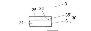
一方図6および図7に示すように、仮設階段としての用途が終了した後に仮組状態の階段に取り付けられる化粧段板25は、下地段板21の上面を覆うように貼り付けられるものであり、前端縁に段鼻4が一体に形成されている。段鼻4は化粧段板25の前端縁から前方に延びてから下方に折り返されて、その下方折り返し部が下地段板21の前端縁を前方から覆うことができるようになっている。
On the other hand, as shown in FIG. 6 and FIG. 7, the
図8に示すように化粧段板25の厚さT2は、既述したように下地段板21の上面とけこみ板3の化粧段板挿入部35との間の間隔に対応する化粧段板挿入部35の巾W2よりも少し大きく(厚く)形成されている。なお下地段板21における切欠凹段部22の前端位置は上位のけこみ板3の前面によりも前方に配置されているため、その前端位置と、けこみ板3における段板挿入溝30の上側開口縁部との間に形成された斜め向き隙間の間隔Lが、化粧段板25の厚さT2よりも大きく形成されている。
As shown in FIG. 8, the thickness T <b> 2 of the
本実施形態において化粧段板25の材料としては、木質系材料を用いることができ、例えば6mm〜18mm厚のPB(パーティクルボード)やMDF(中密度繊維板)等を好適に用いることができる。本実施形態の化粧段板25の材料としては、12mm厚のPBまたは9mm厚のMDFが採用されている。
In the present embodiment, a wood-based material can be used as the material of the
図1Dおよび図6に示すようにこの化粧段板25を一対の側板1等に組み付けるには、化粧段板25をその後端側が下向きになるような斜め姿勢に配置し、その斜め姿勢のままで化粧段板25の後端縁を、上記斜め向き隙間を介してけこみ板3における化粧段板挿入部35の前部に挿入し、続けて化粧段板25を後方に押し込みつつ水平姿勢になるまで回転させて、化粧段板25の後端縁を化粧段板挿入部35の奥まで差し込む。この差込状態においては、化粧段板25が下地段板21の上面を覆うように配置されるとともに、段鼻4が化粧段板25および下地段板21の前端面を覆うように配置されることにより、下地段板21が段鼻付きの化粧段板25によって化粧が施される。
As shown in FIG. 1D and FIG. 6, in order to assemble the
ここで本実施形態においては、下地段板21の上面後端縁に下地段板切欠凹段部22を形成して、切欠凹段部22の前端と段板挿入溝30の上側開口縁部との間の斜め向き隙間の間隔Lを化粧段板25の厚さT2よりも広く形成しているため、その斜め向き隙間を介して斜め姿勢の化粧段板25の後端縁をけこみ板3の化粧段板挿入部35に支障なく挿入して奥まで嵌め込むことができる。すなわち化粧段板25の厚さT2は、下地段板21の上面および化粧段板挿入部35の上面(天井面)間の隙間寸法W2よりも厚く形成しているため、仮に下地段板21の上面後端部に切欠凹段部22が形成されていないような場合には、化粧段板25が斜め姿勢であっても水平姿勢であっても化粧段板25の後端縁をけこみ板3の化粧段板挿入部35内に挿入することが困難であり、化粧段板25の組付作業が困難になってしまう。
Here, in the present embodiment, the base step plate notch
そこで本実施形態においては、下地段板21の切欠凹段部22の上方に形成される斜め向き隙間の間隔Lが化粧段板25の厚さT2よりも大きいため、その斜め向き隙間に斜め姿勢の化粧段板25の後端縁を確実に挿入できて、既述した通り化粧段板25を回転させつつ化粧段板挿入部35の奥まで確実に差し込むことができる。このように化粧段板25の後端縁を斜め下向きに配置して化粧段板挿入部35に挿入することによって、化粧段板25の後端縁を化粧段板挿入部35にスムーズに挿入できるとともに、化粧段板25を回転させつつ押し込むことによって化粧段板挿入部35の奥までスムーズに差し込むことができる。従って化粧段板25の挿入作業を効率良くスムーズに行うことができ、ひいては組立作業性を一層向上させることができる。
Therefore, in the present embodiment, since the gap L between the diagonal gaps formed above the notched
さらに本実施形態においては、化粧段板25を化粧段板挿入部35に挿入した際に、化粧段板25の下地段板21等に対する位置決めを図ることができるため、化粧段板25を所定の位置に精度良く簡単に配置できて組付作業性をより向上させることができる。
Furthermore, in the present embodiment, when the decorative
その上さらに本実施形態においては、化粧段板25の厚さT2を化粧段板挿入部35の巾W2よりも厚く形成しているため、化粧段板25、下地段板21およびけこみ板3が弾性圧縮変形しながら化粧段板25が化粧段板挿入部35内に挿入される。このため上記の圧縮変形に対する復元力によって化粧段板25の上面が段板挿入溝30の内周上側面に密着し、化粧段板25と段板挿入溝30の上側開口縁部との間に隙間が形成されるのを確実に防止できて、良好な美観を確保することができる。
Furthermore, in this embodiment, since the thickness T2 of the
なお本実施形態において、化粧段板25は下地段板21に糊釘併用で固定される。すなわち図7に示すように化粧段板25および下地段板21間に介在されるように接着剤を塗布しておき、その状態で化粧段板25の両側縁部および前縁部に上方からフィニッシュネイル等の釘55を打ち込んで下地段板21および側板1に固定する。
In the present embodiment, the decorative
こうして化粧段板25を貼り付けて下地段板21に化粧を施すとともに、けこみ板3の前面に貼着された養生フィルム等の養生材を剥離して、けこみ板3の化粧面を露出させる。これにより本実施形態のひな壇階段が仕上げ状態となり階段組立作業が完了する。
In this way, the decorative
以上のように本実施形態の安全施工階段によれば、下地段板21の後端縁をけこみ板3の下地段板挿入部31に挿入して固定しているため、下地段板21の後端縁21をけこみ板3の下地段板挿入部31によって下方側から支持固定することができる。従って下地段板21の後端縁中央部にたわみ変形が生じるのを防止することができる。さらに下地段板21のたわみ変形を防止できるため、下地段板21として薄くて軽量のものを使用でき、コストの削減および組立作業性を向上させることができる。
As described above, according to the safe construction staircase of the present embodiment, the rear edge of the
さらに本実施形態においては、けこみ板3の下地段板挿入部21の奥行きを化粧段板挿入部25の奥行きよりも深く形成しているため、下地段板21を下地段板挿入部21に差し込んだ際に、奥行き方向および下方向の位置決めに加えて上方向の位置決めも図ることができ、下地段板21を精度良く簡単に取り付けることができる。
Further, in the present embodiment, since the depth of the base
また本実施形態の安全施工階段においては、けこみ板3、下地段板21、化粧段板25の組付作業はその釘打ち作業も含めて全て階段前面側からの作業で行うことができる。つまり階段裏面側からの作業が不要となり、組付作業性をより一層向上させることができる。
Moreover, in the safe construction staircase of this embodiment, the assembling work of the scooping
さらに化粧段板25の後端縁を上位のけこみ板3の段板挿入溝30に挿入しているため、化粧段板25の後端縁の収まり具合が良くなり、良好な美観をより確実に得ることができる。
Furthermore, since the rear end edge of the
また化粧段板25の厚さT2を、段板挿入溝30の上側に設けられた化粧段板挿入部35の巾W2よりも厚く形成して、化粧段板25を化粧段板挿入部35に圧縮状態に挿入しているため、化粧段板25の上面が段板挿入溝30の上側開口縁部に密着し隙間が形成されるのを防止でき、美観をより一層向上させることができる。
In addition, the thickness T2 of the
さらに下地段板21の上面後端縁に切欠凹段部22を形成して、その凹段部22を利用して化粧段板25を化粧段板挿入部35に挿入するようにしているため、化粧段板25の厚さが厚くとも、化粧段板挿入部35に確実に挿入することができる。
Furthermore, since the notch
また化粧段板25に段鼻4を一体に形成しているため、化粧段板25の取付と同時に段鼻4を取り付けることができ、実質的に段鼻4の取付作業を省略できて、一段と組付作業性を向上させることができる。
Further, since the
なお上記実施形態においては、本発明を直階段に適用する場合を例に挙げて説明したが、それだけに限られず、本発明は、図1A〜図1Dに示すひな壇階段の上側を構成する回り階段(かね折れ階段も含む)にも上記と同様にして適用することができる。 In the above embodiment, the case where the present invention is applied to a straight staircase has been described as an example. However, the present invention is not limited thereto, and the present invention is not limited to that. It can be applied in the same manner to the above (including a stepped stairs).
また上記実施形態においては、けこみ板3における下地段板挿入部31の奥行きを化粧段板挿入部25の奥行きよりも深く形成しているが、それだけに限られず、本発明においては図9に示すように下地段板挿入部31の奥行きと化粧段板挿入部35の奥行きとを同じ深さに形成しても良いし、下地段板挿入部31の奥行きを化粧段板挿入部35の奥行きよりも浅く形成するようにしても良い。
Moreover, in the said embodiment, although the depth of the base step
また上記実施形態においては、化粧段板25の後端縁を化粧段板挿入部35にスムーズに挿入できるように、下地段板21の後端縁に切欠凹段部22を形成するようにしているが、それだけに限られず、本発明においては図10に示すように化粧段板25の下面後端縁に化粧段板切欠凹部26を形成するようにしても良い。この場合、化粧段板切欠部26が形成されることによって、化粧段板25の後端縁の厚さが薄くなり、その薄い化粧段板後端縁をけこみ板3の段板挿入溝30内における下地段板21の上方に確実に挿入できて、上記実施形態と同様に化粧段板25を回転操作しつつ押し込むことにより、化粧段板25を化粧段板挿入部35の奥まで確実に差し込むことができる。
Further, in the above embodiment, the notched
さらに本発明においては、下地段板21の下面後端縁および化粧段板25の上面後端縁の双方に切欠凹部22,26をそれぞれ形成するようにしても良い。
Further, in the present invention, the notch recesses 22 and 26 may be formed on both the lower surface rear edge of the
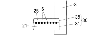
また本発明においては、下地段板21や化粧段板25に切欠凹部等を形成しなくとも化粧段板25を化粧段板挿入部35に圧縮状態に挿入配置することができる。例えば図11に示すように化粧段板25の実質的な厚さ寸法を化粧段板挿入部35の巾寸法よりも薄く形成しておき、化粧段板25を下地段板21に接着するための接着剤6として、硬化時に発泡して膨張する発泡性接着剤を用いるようにすれば良い。この場合、接着剤6の硬化前に化粧段板25を化粧段板挿入溝35内に挿入すれば、その挿入作業を確実に行えるとともに、その後接着剤6が硬化して発泡することによって化粧段板25の上面後端縁を段板挿入溝30の内周上側面に圧接することができ、化粧段板25の上面と段板挿入溝30の上側開口縁部との間に隙間が形成されるのを確実に防止することができる。
Further, in the present invention, the
同様に下地段板21の後端差込部23をけこみ板3の段板挿入溝30の内周下側面に固定する際に、発泡性接着剤によって接着するようにすれば、下地段板21の後端差込部23の厚さT1が下地段板挿入部31の巾W1よりも薄い場合であっても、下地段板21の後端差込部23を下地段板挿入部31に圧縮状態に嵌め込むことができる。
Similarly, when the rear
ここで発泡性接着剤としては、1液型ウレタン系接着剤を好適なものとして例示することができる。なお発泡に限られず、下地段板21や化粧段板25を挿入した後、膨張する(体積が増加する)接着剤であれば、上記の発泡性接着剤と同様に用いることができる。
Here, as the foaming adhesive, a one-component urethane adhesive can be exemplified as a suitable one. Note that the adhesive is not limited to foaming, and can be used in the same manner as the above foaming adhesive as long as the adhesive expands (increases in volume) after the base corrugated
また上記実施形態においては、化粧面に養生フィルム等の養生材が貼り付けられたけこみ板3を組み付けておき、最終的に養生フィルムを剥離して、けこみ板3の化粧面を露出させて仕上げ施工を行うようにしているが、それだけに限られず、本発明においては、化粧が施されていないけこみ板を組み付けておき、最終的にけこみ板の表面に化粧材を貼り付けて仕上げ施工を行うようにしても良い。
Moreover, in the said embodiment, the scoring
また上記実施形態においては、化粧段板25の後端縁をけこみ板3の段板挿入溝30に挿入するようにしているが、それだけに限られず、本発明においては、下地段板21だけをけこみ板3の段板挿入溝30に挿入し、化粧段板25の後端縁は段板挿入溝30に挿入せずにけこみ板3の前面に対向配置させるようにしても良い。
Moreover, in the said embodiment, although the rear-end edge of the
また上記実施形態においては、化粧段板25に段鼻4を一体に形成しているが、それだけに限られず、本発明においては図12に示すように段鼻4を化粧段板25に対し別体に形成するようにしても良い。この場合同図に示すように化粧段板25の前端面に雄ざね部27を形成するとともに、段鼻4の裏面側に雄ざね部27に対応して雌ざね部41を形成しておき、雄ざね部27を雌ざね部41に嵌め込んで段鼻4を化粧段板25等に固定することによって、段鼻4を所定位置に位置精度良く確実に固定することができる。言うまでもなく、段鼻取付用の雄ざね部を下地段板21の前端面に形成するようにしても良い。
In the above embodiment, the
また上記実施形態において例えば、化粧段板25と別体の段鼻4を下地段板21の前端面に固定するような場合、けこみ板3における化粧段板収容部35内に弾性復元力を有するクッション材を圧縮状態に挿入しておくことにより、そのクッション材の復元力によって化粧段板25を前方に押し付けて段鼻5に圧接することができ、化粧段板25を安定した状態に取り付けることができる。
Further, in the above embodiment, for example, when the
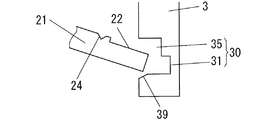
また本発明においては図13Aに示すように、下地段板21における後端差込部23の後端面下縁部に面取り部(下地段板側面取り部)29を形成するようにしても良い。この場合には、後端差込部23の厚さT1が下地段板挿入部31の巾W1よりも厚い場合でも、下地段板21を容易に挿入することができる。また図13Bに示すように、けこみ板3における段板挿入溝30の開口縁部下側に面取り部(けこみ板側面取り部)39を形成しても、上記と同様に後端差込部23の厚さT1が下地段板挿入部31の巾W1よりも厚い場合でも、下地段板21を容易に挿入することができる。言うまでもなく本発明においては、図13Aに示す下地段板側面取り部29と、図13Bに示すけこみ板側面取り部39とを共に形成するようにしても良い。
Further, in the present invention, as shown in FIG. 13A, a chamfered portion (base step plate side chamfered portion) 29 may be formed on the lower edge portion of the rear
また図13Bに示すように、けこみ板側面取り部39を形成する場合には、釘打ち角度にかかわらず下地段板21をけこみ板3に確実に固定することができる。すなわち図14Aに示すように、けこみ板側面取り部39が形成されていない場合、釘打ち角度が高いと(釘打ち方向が垂直に近いと)、釘打ち用溝24から打ち込んだ釘51が段板挿入溝30内に届かず、下地段板21の下方に抜け出してけこみ板3の前面における段板挿入溝30の下側で跳ね返されて折れ曲がってしまい、釘51をけこみ板3に固定できないおそれがある。
Further, as shown in FIG. 13B, when the side plate chamfered
そこで図14Bに示すようにけこみ板側面取り部39を形成しておくと、釘打ち角度が高い場合であっても、釘打ち用溝24から打ち込んだ釘51が面取り部39に導かれるため、釘51をけこみ板3に確実に固定することができる。
14B, the
参考までに図14Cに示すように釘打ち角度が低い場合には、けこみ板側面取り部が39が形成されていなくとも、釘打ち用溝24から打ち込んだ釘51は段板挿入溝30内に導かれるため、釘51をけこみ板3に確実に固定することができる。
For reference, when the nail driving angle is low as shown in FIG. 14C, the
この発明の安全施工階段は、例えば一般住宅等の屋内に組み付けられる木質製のひな壇階段等に適用することができる。 The safe construction staircase of the present invention can be applied to, for example, a wooden stairs that are assembled indoors such as a general house.
1:側板
12:段板取付用木口(段板取付部)
13:けこみ板取付用木口(けこみ板取付部)
14:蹴込板挿入用切欠部
21:下地段板
22:下地段板切欠凹段部
25:化粧段板
26:化粧段板切欠凹段部
27:雄ざね部
29:下地段板側面取り部
3:けこみ板
30:段板挿入溝
31:下地段板挿入部
35:化粧段板挿入部
39:けこみ板側面取り部
4:段鼻
41:雌ざね部
6:接着剤
T1:下地段板後端部の厚さ
T2:化粧段板の厚さ
W1:下地段板挿入部の巾
W2:化粧段板挿入部の巾
1: Side plate 12: Cutout for attaching a stepboard (stepboard attachment portion)
13: Diagonal plate attachment clerk (distance plate attachment part)
14: Notch portion for inserting a kick plate 21: Base step plate 22: Base step plate notch concave step portion 25: Makeup step plate 26: Makeup step plate notch concave step portion 27: Male ridge portion 29: Base step plate side chamfer portion 3 : Kake board 30: Corrugated board insertion groove 31: Base board board insertion part 35: Makeup board board insertion part 39: Kake board side surface taking part 4: Nose 41: Female ridge part 6: Adhesive T1: After the base board board End thickness T2: thickness of decorative step board W1: width of base plate insertion portion W2: width of base plate insertion portion
Claims (18)
前記けこみ板の前面下端部に、前記下地段板の後端に対応して段板挿入溝が形成されるとともに、その段板挿入溝に前記下地段板の後端が挿入された状態に配置されていることを特徴とする安全施工階段。 Provided with a plurality of base plate arranged at intervals in the diagonal direction, the upper end of the squeeze plate arranged between the adjacent base plate is arranged corresponding to the front lower surface of the upper base plate In addition to the temporary state in which the lower end of the front surface of the dent plate is disposed corresponding to the rear end of the lower base plate, a decorative step plate is attached to the upper surface of the base plate and finished. Safe construction stairs
A step plate insertion groove corresponding to the rear end of the base step plate is formed in the front lower end portion of the scraping plate, and the rear end of the base step plate is inserted into the step plate insertion groove. Safe construction stairs characterized by being arranged.
前記段板挿入溝における前記下地段板の上面と前記段板挿入溝の内周上側面との間の隙間が化粧段板挿入部として構成され、
仕上げ状態では前記化粧段板の後端が前記化粧段板挿入部に挿入された状態に配置されている請求項1に記載の安全施工階段。 The lower side of the step plate insertion groove is configured as a base step plate insertion portion for inserting the base step plate,
A gap between the upper surface of the base plate in the step plate insertion groove and the inner peripheral upper side surface of the step plate insertion groove is configured as a decorative step plate insertion portion,
The safe construction staircase according to claim 1, wherein in a finished state, the rear end of the decorative step board is disposed in a state of being inserted into the decorative step board insertion portion.
その下地段板切欠凹部の前端位置が上位のけこみ板の前面よりも前方に配置されている請求項2〜5のいずれか1項に記載の安全施工階段。 A base step plate notch recess is formed at the rear end of the upper surface of the base step plate,
The safety construction stair according to any one of claims 2 to 5, wherein a front end position of the base plate notch recess is disposed in front of a front surface of the upper indenting plate.
仕上げ状態では前記養生材が前記けこみ板から取り外されている請求項1〜11のいずれか1項に記載の安全施工階段。 In the temporary state, a peelable curing material is laminated on the front surface of the rake plate,
The safe construction stair according to any one of claims 1 to 11, wherein in the finished state, the curing material is removed from the rake plate.
仮設状態において前記けこみ板は前記けこみ板化粧材が取り外された状態であり、仕上げ状態では前記けこみ板にけこみ板化粧材が貼り付けられている請求項1〜11のいずれか1項に記載の安全施工階段。 A decorative board decorative material that can be attached to the front surface of the electronic board is provided,
The said board is a state in which the said board decoration material was removed in the temporary state, and the board decoration material is affixed on the said board in the finishing state. Safe construction stairs as described in the section.
前記雄ざね部が前記雌ざね部に嵌め込まれて、前記段鼻が前記化粧段板に取り付けられている請求項14に記載の安全施工階段。 A male ridge is formed on the front end surface of the decorative corrugated board, and a female ridge is formed on the back side of the nose,
The safety construction staircase according to claim 14, wherein the male ridge portion is fitted into the female ridge portion, and the nose is attached to the decorative step board.
前記側板の上端縁に、前記下地段板の両側下面を支持する水平な段板取付部と、前記けこみ板の両側下端を支持する垂直なけこみ板取付部とが交互に設けられ、
前記側板における前記段板取付部の後端に前記けこみ板の下端を挿入配置するためのけこみ板挿入用切欠部が形成されている請求項1〜17のいずれか1項に記載の安全施工階段。
A side plate supporting the side edge of the base plate and the side edge of the rake plate;
On the upper edge of the side plate, horizontal step plate mounting portions that support the lower surfaces of both sides of the base step plate, and vertical scoop plate mounting portions that support the bottom ends of both sides of the scoring plate are alternately provided,
The safety plate according to any one of claims 1 to 17, wherein a notch portion for inserting a dent plate for inserting and arranging a lower end of the dent plate is formed at a rear end of the step plate attachment portion of the side plate. Construction stairs.
Priority Applications (1)
| Application Number | Priority Date | Filing Date | Title |
|---|---|---|---|
| JP2015124372A JP6580388B2 (en) | 2015-06-22 | 2015-06-22 | Safety construction stairs |
Applications Claiming Priority (1)
| Application Number | Priority Date | Filing Date | Title |
|---|---|---|---|
| JP2015124372A JP6580388B2 (en) | 2015-06-22 | 2015-06-22 | Safety construction stairs |
Publications (2)
| Publication Number | Publication Date |
|---|---|
| JP2017008567A true JP2017008567A (en) | 2017-01-12 |
| JP6580388B2 JP6580388B2 (en) | 2019-09-25 |
Family
ID=57761101
Family Applications (1)
| Application Number | Title | Priority Date | Filing Date |
|---|---|---|---|
| JP2015124372A Active JP6580388B2 (en) | 2015-06-22 | 2015-06-22 | Safety construction stairs |
Country Status (1)
| Country | Link |
|---|---|
| JP (1) | JP6580388B2 (en) |
Citations (7)
| Publication number | Priority date | Publication date | Assignee | Title |
|---|---|---|---|---|
| JPS5889529U (en) * | 1981-12-11 | 1983-06-17 | 朝日特殊合板株式会社 | wooden stairs |
| JPH0735979Y2 (en) * | 1990-02-06 | 1995-08-16 | ミサワホーム株式会社 | Floor |
| JPH08144461A (en) * | 1994-09-20 | 1996-06-04 | Sumitomo Forestry Co Ltd | Constitutional way of stairs |
| JPH11247390A (en) * | 1998-03-05 | 1999-09-14 | Sumitomo Forestry Co Ltd | Stairs |
| JP2004197409A (en) * | 2002-12-18 | 2004-07-15 | Ibiken Kk | Build-up simplified stairs |
| JP2013144884A (en) * | 2012-01-13 | 2013-07-25 | Wood One:Kk | Stair for temporary and permanent use and construction method of the same |
| JP2015031090A (en) * | 2013-08-05 | 2015-02-16 | 株式会社ノダ | Staircase structure and staircase construction method |
-
2015
- 2015-06-22 JP JP2015124372A patent/JP6580388B2/en active Active
Patent Citations (7)
| Publication number | Priority date | Publication date | Assignee | Title |
|---|---|---|---|---|
| JPS5889529U (en) * | 1981-12-11 | 1983-06-17 | 朝日特殊合板株式会社 | wooden stairs |
| JPH0735979Y2 (en) * | 1990-02-06 | 1995-08-16 | ミサワホーム株式会社 | Floor |
| JPH08144461A (en) * | 1994-09-20 | 1996-06-04 | Sumitomo Forestry Co Ltd | Constitutional way of stairs |
| JPH11247390A (en) * | 1998-03-05 | 1999-09-14 | Sumitomo Forestry Co Ltd | Stairs |
| JP2004197409A (en) * | 2002-12-18 | 2004-07-15 | Ibiken Kk | Build-up simplified stairs |
| JP2013144884A (en) * | 2012-01-13 | 2013-07-25 | Wood One:Kk | Stair for temporary and permanent use and construction method of the same |
| JP2015031090A (en) * | 2013-08-05 | 2015-02-16 | 株式会社ノダ | Staircase structure and staircase construction method |
Also Published As
| Publication number | Publication date |
|---|---|
| JP6580388B2 (en) | 2019-09-25 |
Similar Documents
| Publication | Publication Date | Title |
|---|---|---|
| JP4685109B2 (en) | Panel assembly set and its construction method | |
| JP6150657B2 (en) | Stair structure and stairs construction method | |
| JP5086694B2 (en) | Vertical skirting boards for stairs, skirting boards for stairs and stairs | |
| JP6580388B2 (en) | Safety construction stairs | |
| JP5986385B2 (en) | Temporary combined stairs and construction method | |
| JP5455448B2 (en) | Stair baseboard structure | |
| JP6522922B2 (en) | Junction structure of stairs and construction method of stairs | |
| JP2011236577A (en) | Stairs, side plate for forming stairs, and stairs construction method | |
| JP6417147B2 (en) | Stairs and their assembly structure | |
| JP3378299B2 (en) | Floor material | |
| JP6328601B2 (en) | Nose member and construction method thereof | |
| JP6055590B2 (en) | Slope material manufacturing method | |
| JP2017203288A (en) | Unit stair and stair lateral plate | |
| JP4703908B2 (en) | Skirting board | |
| JP2012007358A (en) | Stair baseboard cover and housing structure for stair surface side end of stair baseboard therewith | |
| JPS6114512Y2 (en) | ||
| JP6215904B2 (en) | Staircase | |
| JP2015055097A (en) | Stair structure, stair, construction method of stair, and reforming method of stair | |
| JP5603139B2 (en) | Stair baseboard cover | |
| JPS6239249Y2 (en) | ||
| JP2004285728A (en) | Stepping rail for remodeling and remodeling method | |
| JP2021134584A (en) | Fixing structure of riser board, construction method of riser board, and riser board fixing member used for them and riser board | |
| JP2007162413A (en) | Floor finishing structure continuous with rail | |
| JP5603140B2 (en) | Stair baseboard cover and staircase base joint connection structure using the same | |
| JP2013130020A (en) | Stair baseboard |
Legal Events
| Date | Code | Title | Description |
|---|---|---|---|
| A621 | Written request for application examination |
Free format text: JAPANESE INTERMEDIATE CODE: A621 Effective date: 20180312 |
|
| A977 | Report on retrieval |
Free format text: JAPANESE INTERMEDIATE CODE: A971007 Effective date: 20190116 |
|
| A131 | Notification of reasons for refusal |
Free format text: JAPANESE INTERMEDIATE CODE: A131 Effective date: 20190122 |
|
| A521 | Request for written amendment filed |
Free format text: JAPANESE INTERMEDIATE CODE: A523 Effective date: 20190319 |
|
| TRDD | Decision of grant or rejection written | ||
| A01 | Written decision to grant a patent or to grant a registration (utility model) |
Free format text: JAPANESE INTERMEDIATE CODE: A01 Effective date: 20190806 |
|
| A61 | First payment of annual fees (during grant procedure) |
Free format text: JAPANESE INTERMEDIATE CODE: A61 Effective date: 20190828 |
|
| R150 | Certificate of patent or registration of utility model |
Ref document number: 6580388 Country of ref document: JP Free format text: JAPANESE INTERMEDIATE CODE: R150 |
|
| RD02 | Notification of acceptance of power of attorney |
Free format text: JAPANESE INTERMEDIATE CODE: R3D02 |
|
| R250 | Receipt of annual fees |
Free format text: JAPANESE INTERMEDIATE CODE: R250 |
|
| R250 | Receipt of annual fees |
Free format text: JAPANESE INTERMEDIATE CODE: R250 |