JP2016534789A5 - - Google Patents
Download PDFInfo
- Publication number
- JP2016534789A5 JP2016534789A5 JP2016526033A JP2016526033A JP2016534789A5 JP 2016534789 A5 JP2016534789 A5 JP 2016534789A5 JP 2016526033 A JP2016526033 A JP 2016526033A JP 2016526033 A JP2016526033 A JP 2016526033A JP 2016534789 A5 JP2016534789 A5 JP 2016534789A5
- Authority
- JP
- Japan
- Prior art keywords
- balloon
- catheter
- connector
- refrigerant
- refrigerant delivery
- Prior art date
- Legal status (The legal status is an assumption and is not a legal conclusion. Google has not performed a legal analysis and makes no representation as to the accuracy of the status listed.)
- Granted
Links
- 238000002679 ablation Methods 0.000 claims description 19
- 238000000034 method Methods 0.000 claims description 3
- 238000005286 illumination Methods 0.000 claims description 2
- 239000003507 refrigerant Substances 0.000 claims 41
- 238000005057 refrigeration Methods 0.000 claims 13
- 239000012530 fluid Substances 0.000 claims 2
- 230000023298 conjugation with cellular fusion Effects 0.000 claims 1
- 238000007710 freezing Methods 0.000 claims 1
- 230000013011 mating Effects 0.000 claims 1
- 230000021037 unidirectional conjugation Effects 0.000 claims 1
- 241000255925 Diptera Species 0.000 description 1
- 238000003384 imaging method Methods 0.000 description 1
Images


Description
冷凍バルーンアブレーションシステムのいくつかの例は、以下の単数又は複数を備えることができる。前記デリバリラインは、前記中空モータ軸を貫通して当該モータ軸と共に回転するべくこのモータ軸に接続することができる。前記カテーテル軸は、当該カテーテル軸の遠端部および近端部間に延出するとともに、前記遠端部において前記バルーン内部に開口する感圧ルーメンを備えることができる。前記カテーテルカプラは、前記感圧ルーメンに流体接続された排気アセンブリを備えることができる。コネクタは、前記感圧ルーメンに流体接続されたバルーン感圧ポートを備えることができる。前記カテーテルカプラは、前記バルーン感圧ポートに流体接続された圧力トランスデューサーを備えることができる。前記カテーテルカプラは、前記接続チップに固定された軸接続アセンブリと、前記ハウジングに取り付けられるとともに、前記軸接続アセンブリの遠位側に位置するコネクタレセプタクルアセンブリとを備えることができる。前記コネクタレセプタクルアセンブリは、前記コネクタの前記本体を受け入れるためのレセプタクルルーメンを備えることができる。前記圧力トランスデューサーは、前記コネクタレセプタクルアセンブリに取り付けることができる。前記排気アセンブリは、前記コネクタレセプタクルアセンブリを介して前記感圧ルーメンに流体接続することができる。前記感圧ルーメンに圧力レリーフバルブを流体接続することができ、当該圧力レリーフバルブは、前記感圧ルーメン内の圧力がホールド圧以上になった時に開放するように構成することができる。前記圧力レリーフバルブは、処置中に発生するノイズを低減するべくノイズ減衰装置を備えることができる。前記排気アセンブリは、少なくとも1つのユーザ制御排気バルブを備えることができる。そのような排気バルブの一例は、注射器作動式排気バルブとして構成することができる。そのような排気バルブの別の例は、ユーザによるハンドル上のトリガの操作に従って作動するように構成することができる。 Some examples of frozen balloon ablation systems can include one or more of the following. The delivery line can be connected to the motor shaft to pass through the hollow motor shaft and rotate with the motor shaft. The catheter shaft may include a pressure-sensitive lumen that extends between a distal end portion and a proximal end portion of the catheter shaft and opens into the balloon at the distal end portion. The catheter coupler can include an exhaust assembly fluidly connected to the pressure sensitive lumen. The connector can include a balloon pressure sensitive port fluidly connected to the pressure sensitive lumen. The catheter coupler can comprise a pressure transducer fluidly connected to the balloon pressure sensitive port. The catheter coupler may include a shaft connection assembly fixed to the connection tip, and a connector receptacle assembly attached to the housing and positioned on a distal side of the shaft connection assembly. The connector receptacle assembly can include a receptacle lumen for receiving the body of the connector. The pressure transducer can be attached to the connector receptacle assembly. The exhaust assembly may be fluidly connected to the pressure sensitive lumen via the connector receptacle assembly. A pressure relief valve can be fluidly connected to the pressure sensitive lumen, and the pressure relief valve can be configured to open when the pressure in the pressure sensitive lumen becomes equal to or higher than the hold pressure. The pressure relief valve can include a noise attenuator to reduce noise generated during the procedure. The exhaust assembly may comprise at least one user controlled exhaust valve. An example of such an exhaust valve can be configured as a syringe operated exhaust valve. Another example of such an exhaust valve may be configured to operate in accordance with trigger operation of the handle by a user.
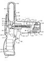
病巣標的化が改良されたアブレーションシステム2の一例が図1および2に図示され、これは、内視鏡4と、図2を参照、図1に図示されているもののような冷凍バルーンアブレーションアセンブリ10、とを有する。前記内視鏡は従来式のものとすることができ、これら近端および遠端部間に延出する通路8を形成する近端部6と遠端部7を備える内視鏡チューブ5を含むことができる。内視鏡4は、前記内視鏡チューブ5内の別の通路9を通過することが可能な、内視鏡的画像化および照明装置を含む、従来式および/又は非従来式の内視鏡装置と共に使用することができる。 An example of an ablation system 2 with improved focus targeting is illustrated in FIGS. 1 and 2, which includes an endoscope 4 and a frozen balloon ablation assembly 10 such as that illustrated in FIG. , And. The endoscope can be conventional and includes an endoscope tube 5 having a proximal end 6 and a distal end 7 forming a passage 8 extending between the proximal and distal ends. be able to. The endoscope 4 includes a conventional and / or non-conventional endoscope that includes an endoscopic imaging and illumination device that can pass through another passage 9 in the endoscope tube 5. Can be used with the device.
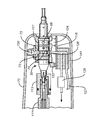
図11および図12に図示されているように、ハンドルアセンブリ14は、ハウジング72内の開口部118に隣接して位置するコネクタレセプタクルアセンブリ116を有する。協働で、前記軸接続アセンブリ110と前記コネクタレセプタクルアセンブリ116とは、カテーテルカプラを構成する。コネクタレセプタクルアセンブリ116は、コネクタアセンブリ30のOリング73間の部分を収納するレセプタクルルーメン117を有する。コネクタアセンブリ30は、開口部118を通って、コネクタレセプタクルアセンブリ116の軸ロック機構120が軸ロック構造66と係合するまで、レセプタクルルーメン117内へと挿入される。マイクロスイッチ123は、コネクタアセンブリ30がコネクタレセプタクルアセンブリ116に正しく接続された時にその表示を制御電子装置94に提供する。これによって、コンポーネントが正しく接続されていない時のハンドルアセンブリ10の作動が防止される。前記デリバリライン100とマニホルド98との境界にはアダプタアセンブリ99、図10を参照、が設けられ、これは前記二つの部材を流体接続する。この実施例において、前記アダプタアセンブリ99は、更に、ステッパモータ軸102と協働して処置中の不意の回転を防止することに役立つ圧力作動ブレーキとして作用する。
As shown in FIGS. 11 and 12, the handle assembly 14 has a
Claims (21)
近端部と遠端部、そしてこれら近端部および遠端部の間に延出するカテーテル軸ルーメンを有するカテーテル軸と、
前記カテーテル軸の前記遠端部に取り付けられた膨張および収縮可能であり、バルーン内部を形成する内面を有するバルーンと、
前記カテーテル軸の前記近端部に設けられたコネクタと、
冷媒デリバリチューブアセンブリと、を含み、
前記バルーンは、遠端部と近端部と中央部分とを有し、
当該冷媒デリバリチューブアセンブリは、
前記カテーテル軸内に収納され、前記カテーテル軸に対して回転移動する冷媒デリバリチューブを備え、
当該冷媒デリバリチューブは前記コネクタに向けた開口近端部と、前記バルーンの開口遠端部と、これらの間に延出する冷媒デリバリルーメンと、を有し、
前記冷媒デリバリチューブの前記遠端部に設けられた冷媒デリバリエレメントを備え、
当該冷媒デリバリエレメントは、前記バルーン内部内に出口を有し、当該出口は前記冷媒デリバリチューブの前記開口遠端部に流体接続されるとともに、当該出口は、前記冷媒デリバリチューブの回転向きに応じた様々な回転位置で前記バルーンの前記内面に向けて外側に冷媒を向けるように構成されており、
前記近端部と前記遠端部とを有する第1長手部材を備え、当該第1長手部材の前記近端部は、前記冷媒デリバリエレメントに接続され、前記第1長手部材は前記冷媒デリバリエレメントから遠位側に延出しており、
前記第1長手部材に接続されるとともに当該第1長手部材から遠位側に延出する第2長手部材を備え、前記バルーンの遠位部分は前記第2長手部材に固定されており、そして、
前記第1長手部材は、前記冷媒デリバリエレメントと中空チップ延出部との少なくとも一方にスライド可能に接続されている冷凍アブレーションカテーテル。 A cryoablation catheter,
A catheter shaft having a proximal end and a distal end, and a catheter shaft lumen extending between the proximal and distal ends;
A balloon having an inner surface that is inflatable and deflate attached to the distal end of the catheter shaft and forms a balloon interior;
A connector provided at the proximal end of the catheter shaft;
A refrigerant delivery tube assembly, and
The balloon has a distal end, a proximal end, and a central portion;
The refrigerant delivery tube assembly is
A refrigerant delivery tube that is housed in the catheter shaft and rotates relative to the catheter shaft;
The refrigerant delivery tube has an opening near end facing the connector, an opening far end of the balloon, and a refrigerant delivery lumen extending therebetween.
Comprising a refrigerant delivery element provided at the far end of the refrigerant delivery tube;
The refrigerant delivery element has an outlet inside the balloon. The outlet is fluidly connected to the far end of the opening of the refrigerant delivery tube, and the outlet corresponds to the rotation direction of the refrigerant delivery tube. It is configured to direct the refrigerant outward toward the inner surface of the balloon at various rotational positions ,
A first longitudinal member having the proximal end and the distal end; the proximal end of the first longitudinal member being connected to the refrigerant delivery element; and the first longitudinal member from the refrigerant delivery element Extending distally,
A second longitudinal member connected to the first longitudinal member and extending distally from the first longitudinal member, the distal portion of the balloon being secured to the second longitudinal member; and
The first longitudinal member is a cryoablation catheter slidably connected to at least one of the refrigerant delivery element and the hollow tip extension .
冷凍アブレーションカテーテルを備え、当該冷凍アブレーションカテーテルは以下を有する、
近端部と遠端部、そしてこれら近端部および遠端部の間に延出するカテーテル軸ルーメンを有するカテーテル軸と、
前記カテーテル軸の前記遠端部に取り付けられた膨張および収縮可能であり、バルーン内部を形成する内面を有するバルーンと、
前記カテーテル軸の前記近端部に設けられたコネクタと、
前記コネクタは、冷媒デリバリチューブに固定された接続チップとおよび本体を有し、前記接続チップと前記冷媒デリバリチューブとは共に、前記コネクタの前記本体に対して回転可能であり、そして、
冷媒デリバリチューブアセンブリを備え、当該冷媒デリバリチューブアセンブリは、前記カテーテル軸内に収納され、前記カテーテル軸に対して回転移動する前記冷媒デリバリチューブを備え、当該冷媒デリバリチューブは前記コネクタに向けた開口近端部と、前記バルーンの開口遠端部と、これらの間に延出する冷媒デリバリルーメンと、を有し、
前記冷媒デリバリチューブの前記遠端部に設けられた冷媒デリバリエレメントを備え、当該冷媒デリバリエレメントは、前記バルーン内部内に出口を有し、当該出口は前記冷媒デリバリチューブの前記開口遠端部に流体接続されるとともに、当該出口は、前記冷媒デリバリチューブの回転向きに応じた様々な回転位置で前記バルーンの前記内面に向けて外
側に冷媒を向けるように構成されており、
ハンドルアセンブリを備え、
前記ハンドルアセンブリは冷凍ガス源に接続され、前記ハンドルアセンブリは、
ハウジングと、
前記ハウジングに取り付けられるとともに、前記コネクタと嵌合係合するように構成されたカテーテルカプラと、
前記ハウジングに取り付けられるとともに、中空の回転可能なモータ軸を有するモータと、
前記冷凍ガス源に流体接続されて前記冷媒デリバリチューブの前記開口近端部に冷凍ガスを供給するデリバリラインと、を備え、
前記冷媒デリバリチューブと前記デリバリラインとの少なくとも一方が中空モータ軸を少なくとも部分的に通過し、そして、前記冷凍ガス源を前記デリバリラインに選択的に流体接続するユーザ作動式バルブを備え、そして、前記接続チップと前記冷媒デリバリチューブは、前記中空モータ軸に、当該軸とともに回転移動するように作動接続されている冷凍バルーンアブレーションシステム。 A frozen balloon ablation system,
Comprising a cryo, the cryoablation catheter having a following,
A catheter shaft having a proximal end and a distal end, and a catheter shaft lumen extending between the proximal and distal ends;
A balloon having an inner surface that is inflatable and deflate attached to the distal end of the catheter shaft and forms a balloon interior;
A connector provided at the proximal end of the catheter shaft;
The connector has a connection tip fixed to a refrigerant delivery tube and a body, the connection tip and the refrigerant delivery tube are both rotatable relative to the body of the connector; and
A refrigerant delivery tube assembly, wherein the refrigerant delivery tube assembly is housed in the catheter shaft and includes the refrigerant delivery tube that rotates relative to the catheter shaft, the refrigerant delivery tube being near an opening toward the connector. An end, an open distal end of the balloon, and a refrigerant delivery lumen extending therebetween,
The refrigerant delivery element includes a refrigerant delivery element provided at the far end of the refrigerant delivery tube, the refrigerant delivery element has an outlet inside the balloon, and the outlet is a fluid at the far end of the refrigerant delivery tube. The outlet is configured to direct the refrigerant outward toward the inner surface of the balloon at various rotational positions according to the rotational direction of the refrigerant delivery tube.
A handle assembly,
The handle assembly is connected to a refrigeration gas source, and the handle assembly is
A housing;
A catheter coupler attached to the housing and configured for mating engagement with the connector;
A motor attached to the housing and having a hollow rotatable motor shaft;
A delivery line that is fluidly connected to the refrigeration gas source and supplies refrigeration gas to the opening near end of the refrigerant delivery tube;
Comprising at least one of the refrigerant delivery tube and the delivery line at least partially through a hollow motor shaft, and a user-actuated valve that selectively fluidly connects the refrigeration gas source to the delivery line; and The freezing balloon ablation system in which the connection chip and the refrigerant delivery tube are operatively connected to the hollow motor shaft so as to rotate together with the shaft.
ションシステム。 The frozen balloon ablation system according to claim 8 , wherein the delivery line is connected to the motor shaft so as to pass through the hollow motor shaft and rotate together with the hollow motor shaft.
前記接続チップに固定された軸接続アセンブリと、
前記ハウジングに取り付けられるとともに、前記軸接続アセンブリの遠位側に位置し、かつ、前記コネクタの前記本体を受けるためのレセプタクルルーメンを有する、コネクタレセプタクルアセンブリと、を備え、前記圧力トランスデューサーは、前記コネクタレセプタクルアセンブリに取り付けられ、前記排気アセンブリは前記コネクタレセプタクルアセンブリを通して前記第2感圧ルーメンに流体接続されている請求項12に記載の冷凍バルーンアブレーションシステム。 The catheter coupler is
A shaft connection assembly secured to the connection tip;
A connector receptacle assembly attached to the housing and located distally of the shaft connection assembly and having a receptacle lumen for receiving the body of the connector, the pressure transducer comprising: The frozen balloon ablation system of claim 12 , wherein the cryoballoon ablation system is attached to a connector receptacle assembly and the exhaust assembly is fluidly connected to the second pressure sensitive lumen through the connector receptacle assembly.
前記ハンドルアセンブリは、前記第1ユーザ制御排気バルブに作動接続されたユーザ作動アクチュエータを有し、そして、
前記第2ユーザ制御排気バルブは、注射器作動式バルブを有する請求項11に記載の冷凍バルーンアブレーションシステム。 The exhaust assembly includes a first user controlled exhaust valve and a second user controlled exhaust valve fluidly connected to the second pressure sensitive lumen;
The handle assembly includes a user-actuated actuator operatively connected to the first user-controlled exhaust valve; and
The frozen balloon ablation system of claim 11 , wherein the second user-controlled exhaust valve comprises a syringe operated valve.
前記ハンドルアセンブリは、
ハンドルハウジングと、前記ハンドルハウジングに接続された冷凍ガス源と、前記ハンドルハウジングに取り付けられるとともに、前記コネクタと嵌合係合するように構成されたカテーテルカプラと、
前記ハンドルハウジングに取り付けられるとともに、中空の回転可能なモータ軸を有するモータと、
前記冷凍ガス源に流体接続されて前記冷媒ルーメンに冷凍ガスを供給するデリバリラインと、当該デリバリラインは、中空モータ軸を通過し、かつ、当該中空モータ軸と共に回転するべくこのモータ軸に接続されており、
前記冷凍ガス源を前記デリバリラインに選択的に流体接続するユーザ作動式バルブを備え、そして、
前記中空の回転可能な前記モータ軸は、冷凍アブレーションカテーテルを回転運動するべく、前記コネクタの前記接続チップに作動接続されているハンドルアセンブリ。 A handle assembly for use with a cryoablation catheter of the type having a refrigerant lumen and having a catheter shaft with a connector at the proximal end of the catheter shaft, said connector comprising a connecting tip,
The handle assembly is
A handle housing, a cryogenic gas source connected to the handle housing, a catheter coupler attached to the handle housing and configured to engage and engage the connector;
A motor attached to the handle housing and having a hollow rotatable motor shaft;
A delivery line that is fluidly connected to the refrigeration gas source to supply refrigeration gas to the refrigerant lumen, and the delivery line is connected to the motor shaft to pass through the hollow motor shaft and to rotate with the hollow motor shaft. And
A user-actuated valve for selectively fluidly connecting the refrigeration gas source to the delivery line; and
The handle assembly in which the hollow rotatable motor shaft is operatively connected to the connecting tip of the connector for rotational movement of a cryoablation catheter .
冷媒ルーメンを形成しその近端部にコネクタを備えるカテーテル軸を有する冷凍アブレーションカテーテルを備え、前記コネクタは接続チップを備え、
ハンドルアセンブリを備え、前記ハンドルアセンブリは、
ハンドルハウジングと、前記ハンドルアセンブリに接続された冷凍ガス源と、前記ハンドルハウジングに取り付けられるとともに、前記コネクタと嵌合係合するように構成されたカテーテルカプラと、
前記ハンドルハウジングに取り付けられるとともに、中空の回転可能なモータ軸を有するモータと、
前記冷凍ガス源に流体接続されて前記冷媒ルーメンに冷凍ガスを供給するデリバリラインと、当該デリバリラインは、中空モータ軸を通過し、かつ、当該中空モータ軸と共に回転するべくこのモータ軸に接続されており、
前記冷凍ガス源を前記デリバリラインに選択的に流体接続するユーザ作動式バルブを備え、そして、
前記中空の回転可能な前記モータ軸は、前記接続チップと前記カテーテル軸とにそれらと共に回転運動するべく作動接続されている冷凍バルーンアブレーションシステム。 A frozen balloon ablation system,
A cryoablation catheter having a catheter shaft that forms a refrigerant lumen and has a connector at its proximal end, the connector comprising a connection tip,
A handle assembly, the handle assembly comprising:
A handle housing, a cryogenic gas source connected to the handle assembly, a catheter coupler attached to the handle housing and configured to matingly engage with the connector;
A motor attached to the handle housing and having a hollow rotatable motor shaft;
A delivery line that is fluidly connected to the refrigeration gas source and supplies refrigeration gas to the refrigerant lumen, and the delivery line is connected to the motor shaft to pass through the hollow motor shaft and to rotate with the hollow motor shaft. And
A user-actuated valve for selectively fluidly connecting the refrigeration gas source to the delivery line; and
The hollow balloon ablation system wherein the hollow rotatable motor shaft is operatively connected to the connecting tip and the catheter shaft for rotational movement therewith.
Applications Claiming Priority (3)
| Application Number | Priority Date | Filing Date | Title |
|---|---|---|---|
| US201361899077P | 2013-11-01 | 2013-11-01 | |
| US61/899,077 | 2013-11-01 | ||
| PCT/US2014/063518 WO2015066521A1 (en) | 2013-11-01 | 2014-10-31 | Cryogenic balloon ablation system |
Related Child Applications (1)
| Application Number | Title | Priority Date | Filing Date |
|---|---|---|---|
| JP2018140150A Division JP6811749B2 (en) | 2013-11-01 | 2018-07-26 | Cryoablation catheter, cryoballoon ablation system, and handle assembly |
Publications (3)
| Publication Number | Publication Date |
|---|---|
| JP2016534789A JP2016534789A (en) | 2016-11-10 |
| JP2016534789A5 true JP2016534789A5 (en) | 2017-11-09 |
| JP6402317B2 JP6402317B2 (en) | 2018-10-10 |
Family
ID=53005218
Family Applications (2)
| Application Number | Title | Priority Date | Filing Date |
|---|---|---|---|
| JP2016526033A Active JP6402317B2 (en) | 2013-11-01 | 2014-10-31 | Frozen balloon ablation system |
| JP2018140150A Active JP6811749B2 (en) | 2013-11-01 | 2018-07-26 | Cryoablation catheter, cryoballoon ablation system, and handle assembly |
Family Applications After (1)
| Application Number | Title | Priority Date | Filing Date |
|---|---|---|---|
| JP2018140150A Active JP6811749B2 (en) | 2013-11-01 | 2018-07-26 | Cryoablation catheter, cryoballoon ablation system, and handle assembly |
Country Status (5)
| Country | Link |
|---|---|
| US (2) | US9050073B2 (en) |
| EP (1) | EP3062720B1 (en) |
| JP (2) | JP6402317B2 (en) |
| CN (2) | CN105705108B (en) |
| WO (1) | WO2015066521A1 (en) |
Families Citing this family (29)
| Publication number | Priority date | Publication date | Assignee | Title |
|---|---|---|---|---|
| US8382746B2 (en) | 2008-11-21 | 2013-02-26 | C2 Therapeutics, Inc. | Cryogenic ablation system and method |
| US20140228875A1 (en) | 2013-02-08 | 2014-08-14 | Nidus Medical, Llc | Surgical device with integrated visualization and cauterization |
| US20150031946A1 (en) | 2013-07-24 | 2015-01-29 | Nidus Medical, Llc | Direct vision cryosurgical probe and methods of use |
| US9687288B2 (en) | 2013-09-30 | 2017-06-27 | Arrinex, Inc. | Apparatus and methods for treating rhinitis |
| US10098685B2 (en) | 2013-10-30 | 2018-10-16 | Medtronic Cryocath Lp | Feedback system for cryoablation of cardiac tissue |
| CN105705108B (en) * | 2013-11-01 | 2017-12-01 | C2治疗公司 | Low temperature sacculus ablation system |
| US9763743B2 (en) | 2014-07-25 | 2017-09-19 | Arrinex, Inc. | Apparatus and method for treating rhinitis |
| US9414878B1 (en) | 2015-05-15 | 2016-08-16 | C2 Therapeutics, Inc. | Cryogenic balloon ablation system |
| US9568918B1 (en) * | 2015-08-27 | 2017-02-14 | Southwest Research Institute | Balloon system |
| EP3413822B1 (en) | 2016-02-11 | 2023-08-30 | Arrinex, Inc. | Device for image guided post-nasal nerve ablation |
| US11871977B2 (en) | 2016-05-19 | 2024-01-16 | Csa Medical, Inc. | Catheter extension control |
| AU2017267476B2 (en) * | 2016-05-20 | 2021-10-14 | Pentax Of America, Inc. | Cryogenic ablation system with rotatable and translatable catheter |
| EP3471638A4 (en) | 2016-06-15 | 2020-03-11 | Arrinex, Inc. | Devices and methods for treating a lateral surface of a nasal cavity |
| WO2018026985A1 (en) * | 2016-08-04 | 2018-02-08 | Csa Medical, Inc. | Rotational cryogen delivery device |
| US11253312B2 (en) | 2016-10-17 | 2022-02-22 | Arrinex, Inc. | Integrated nasal nerve detector ablation-apparatus, nasal nerve locator, and methods of use |
| JP6868694B2 (en) * | 2016-12-09 | 2021-05-12 | セント・ジュード・メディカル,カーディオロジー・ディヴィジョン,インコーポレイテッド | Pulmonary vein isolation balloon catheter |
| EP3360496B1 (en) | 2017-02-10 | 2022-04-06 | Erbe Elektromedizin GmbH | Fluid connection device and cryosurgical probe having same |
| US11278356B2 (en) | 2017-04-28 | 2022-03-22 | Arrinex, Inc. | Systems and methods for locating blood vessels in the treatment of rhinitis |
| CN111263617A (en) * | 2017-08-21 | 2020-06-09 | 波士顿科学医学有限公司 | Method for controlling pressure within an inflatable balloon of an intravascular catheter system |
| US10349997B1 (en) * | 2017-11-27 | 2019-07-16 | Lewis O'Reilly | Cryogenic treatment system |
| WO2020096630A1 (en) * | 2018-11-07 | 2020-05-14 | Biosense Webster (Israel) Ltd. | Cryo-balloon with directional gas control |
| CN109431595B (en) * | 2019-01-28 | 2019-04-26 | 上海导向医疗系统有限公司 | The flexible freezing ablation needle device of low temperature resistant high pressure |
| CN114980827A (en) * | 2019-12-02 | 2022-08-30 | 帕西拉冷冻技术股份有限公司 | Cryogenic device with venting feature |
| CN111481286B (en) * | 2020-04-23 | 2021-03-23 | 中国人民解放军陆军特色医学中心 | Wart body freezing device |
| AU2021324578A1 (en) * | 2020-08-14 | 2023-03-16 | Adagio Medical, Inc. | Novel flow manifold for cryoablation catheter |
| CN112370147B (en) * | 2021-01-15 | 2021-04-09 | 上海安钛克医疗科技有限公司 | Control handle of balloon catheter, balloon catheter and cryoablation system |
| US20220273915A1 (en) * | 2021-02-26 | 2022-09-01 | Alucent Biomedical, Inc. | Apparatus and methods for restoring tissue |
| WO2022261146A1 (en) * | 2021-06-07 | 2022-12-15 | Agil Therapeutics, Inc. | Cryogenic catheter probe, system, and method for selective ablation of mucosa and submucosa of the gastrointestinal tract |
| WO2024073455A1 (en) * | 2022-09-26 | 2024-04-04 | Ágil Therapeutics, Inc. | Catheter, system, and method for selective ablation in the mucosa and submucosa of the gastrointestinal tract |
Family Cites Families (47)
| Publication number | Priority date | Publication date | Assignee | Title |
|---|---|---|---|---|
| US5035705A (en) | 1989-01-13 | 1991-07-30 | Scimed Life Systems, Inc. | Method of purging a balloon catheter |
| US5342301A (en) | 1992-08-13 | 1994-08-30 | Advanced Polymers Incorporated | Multi-lumen balloons and catheters made therewith |
| US6669689B2 (en) * | 1997-02-27 | 2003-12-30 | Cryocath Technologies Inc. | Cryosurgical catheter |
| US7220257B1 (en) * | 2000-07-25 | 2007-05-22 | Scimed Life Systems, Inc. | Cryotreatment device and method |
| US5971979A (en) | 1997-12-02 | 1999-10-26 | Odyssey Technologies, Inc. | Method for cryogenic inhibition of hyperplasia |
| US6432102B2 (en) * | 1999-03-15 | 2002-08-13 | Cryovascular Systems, Inc. | Cryosurgical fluid supply |
| JP2001087303A (en) * | 1999-09-27 | 2001-04-03 | Nidek Co Ltd | Ophthalmic surgery apparatus |
| US6443947B1 (en) | 2000-03-01 | 2002-09-03 | Alexei Marko | Device for thermal ablation of a cavity |
| US6537271B1 (en) | 2000-07-06 | 2003-03-25 | Cryogen, Inc. | Balloon cryogenic catheter |
| JP4021141B2 (en) * | 2000-10-20 | 2007-12-12 | 株式会社ニデック | Vitreous surgery device |
| EP1429820A4 (en) | 2001-09-27 | 2007-11-14 | Galil Medical Ltd | Cryoplasty apparatus and method |
| US20030088240A1 (en) * | 2001-11-02 | 2003-05-08 | Vahid Saadat | Methods and apparatus for cryo-therapy |
| TWI235073B (en) * | 2002-08-20 | 2005-07-01 | Toray Industries | Catheter for treating cardiac arrhythmias |
| US8172747B2 (en) * | 2003-09-25 | 2012-05-08 | Hansen Medical, Inc. | Balloon visualization for traversing a tissue wall |
| US7727228B2 (en) | 2004-03-23 | 2010-06-01 | Medtronic Cryocath Lp | Method and apparatus for inflating and deflating balloon catheters |
| US7860555B2 (en) * | 2005-02-02 | 2010-12-28 | Voyage Medical, Inc. | Tissue visualization and manipulation system |
| US8992515B2 (en) * | 2005-05-13 | 2015-03-31 | Medtronic Cryocath Lp | Coolant injection tube |
| US20070066961A1 (en) * | 2005-09-21 | 2007-03-22 | Rutter Michael J | Airway balloon dilator |
| WO2007136591A1 (en) * | 2006-05-15 | 2007-11-29 | Baystate Health, Inc. | Balloon endoscope device |
| US8123751B2 (en) | 2006-06-09 | 2012-02-28 | Zimmer Spine, Inc. | Methods and apparatus for access to and/or treatment of the spine |
| US20080312644A1 (en) * | 2007-06-14 | 2008-12-18 | Boston Scientific Scimed, Inc. | Cryogenic balloon ablation instruments and systems |
| JP5562869B2 (en) | 2008-01-11 | 2014-07-30 | ボストン サイエンティフィック サイムド,インコーポレイテッド | Ablation device and method of use |
| EP2259739B1 (en) * | 2008-02-19 | 2015-04-01 | Boston Scientific Scimed, Inc. | Apparatus for uniformly distributing coolant within a cryo-ablation device |
| KR20110000654A (en) * | 2008-03-13 | 2011-01-04 | 보스톤 싸이엔티픽 싸이메드 인코포레이티드 | Cryo-ablation refrigerant distribution catheter |
| CN101584602A (en) * | 2008-05-20 | 2009-11-25 | 上海导向医疗系统有限公司 | Multi-stage precooling cryoablation method and equipment |
| US8187261B2 (en) | 2008-05-29 | 2012-05-29 | Boston Scientific Scimed, Inc. | Regulating internal pressure of a cryotherapy balloon catheter |
| US8226601B2 (en) | 2008-11-12 | 2012-07-24 | Sanovas, Inc. | Resector balloon system |
| US8382746B2 (en) * | 2008-11-21 | 2013-02-26 | C2 Therapeutics, Inc. | Cryogenic ablation system and method |
| US9039626B2 (en) * | 2009-03-31 | 2015-05-26 | Sunnybrook Health Sciences Centre | Medical device with means to improve transmission of torque along a rotational drive shaft |
| JP5843777B2 (en) * | 2009-10-27 | 2016-01-13 | ホライラ, インコーポレイテッド | Delivery device having a coolable energy release assembly |
| US8986293B2 (en) * | 2010-01-27 | 2015-03-24 | Medtronic Cryocath Lp | Cryoballoon refrigerant dispersion control |
| US9402676B2 (en) | 2010-08-26 | 2016-08-02 | Cryomedix, Llc | Cryoablation balloon catheter and related method |
| US8911434B2 (en) * | 2010-10-22 | 2014-12-16 | Medtronic Cryocath Lp | Balloon catheter with deformable fluid delivery conduit |
| US20120158104A1 (en) * | 2010-10-26 | 2012-06-21 | Medtronic Ardian Luxembourg S.A.R.L. | Neuromodulation cryotherapeutic devices and associated systems and methods |
| US11246653B2 (en) | 2010-12-07 | 2022-02-15 | Boaz Avitall | Catheter systems for cardiac arrhythmia ablation |
| US9283022B2 (en) * | 2011-02-01 | 2016-03-15 | Channel Medsystems, Inc. | Methods and apparatus for cryogenic treatment of a body cavity or lumen |
| WO2012162829A1 (en) | 2011-05-27 | 2012-12-06 | Colibri Technologies Inc. | Medical probe with fluid rotary joint |
| US20130018366A1 (en) | 2011-07-11 | 2013-01-17 | C2 Therapeutics | Focal Ablation Assembly |
| US9314588B2 (en) * | 2011-10-28 | 2016-04-19 | Medtronic Cryocath Lp | Systems and methods for variable injection flow |
| US9220556B2 (en) * | 2012-01-27 | 2015-12-29 | Medtronic Cryocath Lp | Balloon design to enhance cooling uniformity |
| US9144449B2 (en) | 2012-03-02 | 2015-09-29 | Csa Medical, Inc. | Cryosurgery system |
| US9241752B2 (en) * | 2012-04-27 | 2016-01-26 | Medtronic Ardian Luxembourg S.A.R.L. | Shafts with pressure relief in cryotherapeutic catheters and associated devices, systems, and methods |
| CN105705108B (en) * | 2013-11-01 | 2017-12-01 | C2治疗公司 | Low temperature sacculus ablation system |
| US9510743B2 (en) * | 2013-12-17 | 2016-12-06 | Biovision Technologies, Llc | Stabilized surgical device for performing a sphenopalatine ganglion block procedure |
| US9855089B2 (en) * | 2014-03-21 | 2018-01-02 | Medtronic Cryocath Lp | Shape changing ablation balloon |
| US9936997B2 (en) * | 2014-05-28 | 2018-04-10 | Kyphon SÀRL | Cryogenic kyphoplasty instrument and methods of use |
| US9414878B1 (en) | 2015-05-15 | 2016-08-16 | C2 Therapeutics, Inc. | Cryogenic balloon ablation system |
-
2014
- 2014-10-31 CN CN201480058955.0A patent/CN105705108B/en active Active
- 2014-10-31 JP JP2016526033A patent/JP6402317B2/en active Active
- 2014-10-31 CN CN201711084674.4A patent/CN107669332B/en active Active
- 2014-10-31 EP EP14858416.2A patent/EP3062720B1/en active Active
- 2014-10-31 US US14/530,288 patent/US9050073B2/en active Active
- 2014-10-31 WO PCT/US2014/063518 patent/WO2015066521A1/en active Application Filing
-
2015
- 2015-03-24 US US14/667,421 patent/US9700364B2/en active Active
-
2018
- 2018-07-26 JP JP2018140150A patent/JP6811749B2/en active Active
Similar Documents
| Publication | Publication Date | Title |
|---|---|---|
| JP2016534789A5 (en) | ||
| JP6811749B2 (en) | Cryoablation catheter, cryoballoon ablation system, and handle assembly | |
| US11534190B2 (en) | Medical systems, devices, and related methods | |
| JP5752444B2 (en) | Internally pressurized medical device | |
| JP4922690B2 (en) | Endoscope fluid supply device and endoscope | |
| US20160113655A1 (en) | Reposable multiplatform endoscopic surgical clip applier | |
| US9511213B2 (en) | Coupling for a medical instrument | |
| JP2017506100A (en) | Atherectomy catheter and occlusion crossing device | |
| JP2017502734A5 (en) | ||
| JP2009527337A (en) | Endoscope suction device | |
| JP2011514201A5 (en) | ||
| JP7398419B2 (en) | trocar | |
| US20190290311A1 (en) | Endoscopic Tool for Facilitating Injection of a Fluid into a Submucosal Layer of Tissue | |
| US20200205649A1 (en) | Endoscope unblocking flush system | |
| US11607484B2 (en) | Variable suction control | |
| CN106659358B (en) | Fluid spigot and insertion equipment | |
| JP2012045326A5 (en) | ||
| JP6472078B2 (en) | Endoscope system | |
| JP2017217109A (en) | Fluid control device of endoscope |