EP3360496B1 - Fluid connection device and cryosurgical probe having same - Google Patents
Fluid connection device and cryosurgical probe having same Download PDFInfo
- Publication number
- EP3360496B1 EP3360496B1 EP17155740.8A EP17155740A EP3360496B1 EP 3360496 B1 EP3360496 B1 EP 3360496B1 EP 17155740 A EP17155740 A EP 17155740A EP 3360496 B1 EP3360496 B1 EP 3360496B1
- Authority
- EP
- European Patent Office
- Prior art keywords
- line
- adhesive
- socket
- fluid
- inner line
- Prior art date
- Legal status (The legal status is an assumption and is not a legal conclusion. Google has not performed a legal analysis and makes no representation as to the accuracy of the status listed.)
- Active
Links
- 239000012530 fluid Substances 0.000 title claims description 75
- 239000000523 sample Substances 0.000 title claims description 7
- 239000000853 adhesive Substances 0.000 claims description 60
- 230000001070 adhesive effect Effects 0.000 claims description 60
- 230000002093 peripheral effect Effects 0.000 claims description 18
- 125000006850 spacer group Chemical group 0.000 claims description 9
- 238000004891 communication Methods 0.000 claims description 3
- 238000003780 insertion Methods 0.000 claims 1
- 230000037431 insertion Effects 0.000 claims 1
- 229920003023 plastic Polymers 0.000 description 9
- 238000004026 adhesive bonding Methods 0.000 description 8
- 239000004033 plastic Substances 0.000 description 7
- 238000000034 method Methods 0.000 description 5
- 238000007789 sealing Methods 0.000 description 5
- 230000004888 barrier function Effects 0.000 description 4
- 239000004020 conductor Substances 0.000 description 4
- 238000002347 injection Methods 0.000 description 4
- 239000007924 injection Substances 0.000 description 4
- 238000004519 manufacturing process Methods 0.000 description 4
- 239000007789 gas Substances 0.000 description 3
- 239000007788 liquid Substances 0.000 description 3
- 230000000712 assembly Effects 0.000 description 2
- 238000000429 assembly Methods 0.000 description 2
- 239000003292 glue Substances 0.000 description 2
- 230000005499 meniscus Effects 0.000 description 2
- 238000003848 UV Light-Curing Methods 0.000 description 1
- 238000001723 curing Methods 0.000 description 1
- 239000012636 effector Substances 0.000 description 1
- 230000000694 effects Effects 0.000 description 1
- 230000002349 favourable effect Effects 0.000 description 1
- 238000001746 injection moulding Methods 0.000 description 1
- 230000010354 integration Effects 0.000 description 1
- 238000005304 joining Methods 0.000 description 1
- 239000000463 material Substances 0.000 description 1
- 229910052751 metal Inorganic materials 0.000 description 1
- 239000002184 metal Substances 0.000 description 1
- 150000002739 metals Chemical class 0.000 description 1
- 238000003825 pressing Methods 0.000 description 1
- 230000005855 radiation Effects 0.000 description 1
- 230000007704 transition Effects 0.000 description 1
Images


Classifications
-
- A—HUMAN NECESSITIES
- A61—MEDICAL OR VETERINARY SCIENCE; HYGIENE
- A61B—DIAGNOSIS; SURGERY; IDENTIFICATION
- A61B18/00—Surgical instruments, devices or methods for transferring non-mechanical forms of energy to or from the body
-
- A—HUMAN NECESSITIES
- A61—MEDICAL OR VETERINARY SCIENCE; HYGIENE
- A61B—DIAGNOSIS; SURGERY; IDENTIFICATION
- A61B18/00—Surgical instruments, devices or methods for transferring non-mechanical forms of energy to or from the body
- A61B18/02—Surgical instruments, devices or methods for transferring non-mechanical forms of energy to or from the body by cooling, e.g. cryogenic techniques
-
- A—HUMAN NECESSITIES
- A61—MEDICAL OR VETERINARY SCIENCE; HYGIENE
- A61B—DIAGNOSIS; SURGERY; IDENTIFICATION
- A61B17/00—Surgical instruments, devices or methods, e.g. tourniquets
-
- A—HUMAN NECESSITIES
- A61—MEDICAL OR VETERINARY SCIENCE; HYGIENE
- A61B—DIAGNOSIS; SURGERY; IDENTIFICATION
- A61B17/00—Surgical instruments, devices or methods, e.g. tourniquets
- A61B17/00491—Surgical glue applicators
-
- B—PERFORMING OPERATIONS; TRANSPORTING
- B29—WORKING OF PLASTICS; WORKING OF SUBSTANCES IN A PLASTIC STATE IN GENERAL
- B29C—SHAPING OR JOINING OF PLASTICS; SHAPING OF MATERIAL IN A PLASTIC STATE, NOT OTHERWISE PROVIDED FOR; AFTER-TREATMENT OF THE SHAPED PRODUCTS, e.g. REPAIRING
- B29C65/00—Joining or sealing of preformed parts, e.g. welding of plastics materials; Apparatus therefor
- B29C65/02—Joining or sealing of preformed parts, e.g. welding of plastics materials; Apparatus therefor by heating, with or without pressure
- B29C65/14—Joining or sealing of preformed parts, e.g. welding of plastics materials; Apparatus therefor by heating, with or without pressure using wave energy, i.e. electromagnetic radiation, or particle radiation
- B29C65/1403—Joining or sealing of preformed parts, e.g. welding of plastics materials; Apparatus therefor by heating, with or without pressure using wave energy, i.e. electromagnetic radiation, or particle radiation characterised by the type of electromagnetic or particle radiation
- B29C65/1406—Ultraviolet [UV] radiation
-
- B—PERFORMING OPERATIONS; TRANSPORTING
- B29—WORKING OF PLASTICS; WORKING OF SUBSTANCES IN A PLASTIC STATE IN GENERAL
- B29C—SHAPING OR JOINING OF PLASTICS; SHAPING OF MATERIAL IN A PLASTIC STATE, NOT OTHERWISE PROVIDED FOR; AFTER-TREATMENT OF THE SHAPED PRODUCTS, e.g. REPAIRING
- B29C65/00—Joining or sealing of preformed parts, e.g. welding of plastics materials; Apparatus therefor
- B29C65/02—Joining or sealing of preformed parts, e.g. welding of plastics materials; Apparatus therefor by heating, with or without pressure
- B29C65/14—Joining or sealing of preformed parts, e.g. welding of plastics materials; Apparatus therefor by heating, with or without pressure using wave energy, i.e. electromagnetic radiation, or particle radiation
- B29C65/1429—Joining or sealing of preformed parts, e.g. welding of plastics materials; Apparatus therefor by heating, with or without pressure using wave energy, i.e. electromagnetic radiation, or particle radiation characterised by the way of heating the interface
- B29C65/1435—Joining or sealing of preformed parts, e.g. welding of plastics materials; Apparatus therefor by heating, with or without pressure using wave energy, i.e. electromagnetic radiation, or particle radiation characterised by the way of heating the interface at least passing through one of the parts to be joined, i.e. transmission welding
-
- B—PERFORMING OPERATIONS; TRANSPORTING
- B29—WORKING OF PLASTICS; WORKING OF SUBSTANCES IN A PLASTIC STATE IN GENERAL
- B29C—SHAPING OR JOINING OF PLASTICS; SHAPING OF MATERIAL IN A PLASTIC STATE, NOT OTHERWISE PROVIDED FOR; AFTER-TREATMENT OF THE SHAPED PRODUCTS, e.g. REPAIRING
- B29C65/00—Joining or sealing of preformed parts, e.g. welding of plastics materials; Apparatus therefor
- B29C65/48—Joining or sealing of preformed parts, e.g. welding of plastics materials; Apparatus therefor using adhesives, i.e. using supplementary joining material; solvent bonding
- B29C65/4805—Joining or sealing of preformed parts, e.g. welding of plastics materials; Apparatus therefor using adhesives, i.e. using supplementary joining material; solvent bonding characterised by the type of adhesives
- B29C65/483—Reactive adhesives, e.g. chemically curing adhesives
- B29C65/4845—Radiation curing adhesives, e.g. UV light curing adhesives
-
- B—PERFORMING OPERATIONS; TRANSPORTING
- B29—WORKING OF PLASTICS; WORKING OF SUBSTANCES IN A PLASTIC STATE IN GENERAL
- B29C—SHAPING OR JOINING OF PLASTICS; SHAPING OF MATERIAL IN A PLASTIC STATE, NOT OTHERWISE PROVIDED FOR; AFTER-TREATMENT OF THE SHAPED PRODUCTS, e.g. REPAIRING
- B29C65/00—Joining or sealing of preformed parts, e.g. welding of plastics materials; Apparatus therefor
- B29C65/48—Joining or sealing of preformed parts, e.g. welding of plastics materials; Apparatus therefor using adhesives, i.e. using supplementary joining material; solvent bonding
- B29C65/52—Joining or sealing of preformed parts, e.g. welding of plastics materials; Apparatus therefor using adhesives, i.e. using supplementary joining material; solvent bonding characterised by the way of applying the adhesive
- B29C65/54—Joining or sealing of preformed parts, e.g. welding of plastics materials; Apparatus therefor using adhesives, i.e. using supplementary joining material; solvent bonding characterised by the way of applying the adhesive between pre-assembled parts
- B29C65/548—Joining or sealing of preformed parts, e.g. welding of plastics materials; Apparatus therefor using adhesives, i.e. using supplementary joining material; solvent bonding characterised by the way of applying the adhesive between pre-assembled parts by capillarity
-
- B—PERFORMING OPERATIONS; TRANSPORTING
- B29—WORKING OF PLASTICS; WORKING OF SUBSTANCES IN A PLASTIC STATE IN GENERAL
- B29C—SHAPING OR JOINING OF PLASTICS; SHAPING OF MATERIAL IN A PLASTIC STATE, NOT OTHERWISE PROVIDED FOR; AFTER-TREATMENT OF THE SHAPED PRODUCTS, e.g. REPAIRING
- B29C66/00—General aspects of processes or apparatus for joining preformed parts
- B29C66/01—General aspects dealing with the joint area or with the area to be joined
- B29C66/05—Particular design of joint configurations
- B29C66/10—Particular design of joint configurations particular design of the joint cross-sections
- B29C66/12—Joint cross-sections combining only two joint-segments; Tongue and groove joints; Tenon and mortise joints; Stepped joint cross-sections
- B29C66/122—Joint cross-sections combining only two joint-segments, i.e. one of the parts to be joined comprising only two joint-segments in the joint cross-section
- B29C66/1222—Joint cross-sections combining only two joint-segments, i.e. one of the parts to be joined comprising only two joint-segments in the joint cross-section comprising at least a lapped joint-segment
-
- B—PERFORMING OPERATIONS; TRANSPORTING
- B29—WORKING OF PLASTICS; WORKING OF SUBSTANCES IN A PLASTIC STATE IN GENERAL
- B29C—SHAPING OR JOINING OF PLASTICS; SHAPING OF MATERIAL IN A PLASTIC STATE, NOT OTHERWISE PROVIDED FOR; AFTER-TREATMENT OF THE SHAPED PRODUCTS, e.g. REPAIRING
- B29C66/00—General aspects of processes or apparatus for joining preformed parts
- B29C66/01—General aspects dealing with the joint area or with the area to be joined
- B29C66/05—Particular design of joint configurations
- B29C66/10—Particular design of joint configurations particular design of the joint cross-sections
- B29C66/12—Joint cross-sections combining only two joint-segments; Tongue and groove joints; Tenon and mortise joints; Stepped joint cross-sections
- B29C66/122—Joint cross-sections combining only two joint-segments, i.e. one of the parts to be joined comprising only two joint-segments in the joint cross-section
- B29C66/1224—Joint cross-sections combining only two joint-segments, i.e. one of the parts to be joined comprising only two joint-segments in the joint cross-section comprising at least a butt joint-segment
-
- B—PERFORMING OPERATIONS; TRANSPORTING
- B29—WORKING OF PLASTICS; WORKING OF SUBSTANCES IN A PLASTIC STATE IN GENERAL
- B29C—SHAPING OR JOINING OF PLASTICS; SHAPING OF MATERIAL IN A PLASTIC STATE, NOT OTHERWISE PROVIDED FOR; AFTER-TREATMENT OF THE SHAPED PRODUCTS, e.g. REPAIRING
- B29C66/00—General aspects of processes or apparatus for joining preformed parts
- B29C66/01—General aspects dealing with the joint area or with the area to be joined
- B29C66/32—Measures for keeping the burr form under control; Avoiding burr formation; Shaping the burr
- B29C66/322—Providing cavities in the joined article to collect the burr
-
- B—PERFORMING OPERATIONS; TRANSPORTING
- B29—WORKING OF PLASTICS; WORKING OF SUBSTANCES IN A PLASTIC STATE IN GENERAL
- B29C—SHAPING OR JOINING OF PLASTICS; SHAPING OF MATERIAL IN A PLASTIC STATE, NOT OTHERWISE PROVIDED FOR; AFTER-TREATMENT OF THE SHAPED PRODUCTS, e.g. REPAIRING
- B29C66/00—General aspects of processes or apparatus for joining preformed parts
- B29C66/50—General aspects of joining tubular articles; General aspects of joining long products, i.e. bars or profiled elements; General aspects of joining single elements to tubular articles, hollow articles or bars; General aspects of joining several hollow-preforms to form hollow or tubular articles
- B29C66/51—Joining tubular articles, profiled elements or bars; Joining single elements to tubular articles, hollow articles or bars; Joining several hollow-preforms to form hollow or tubular articles
- B29C66/52—Joining tubular articles, bars or profiled elements
- B29C66/522—Joining tubular articles
- B29C66/5221—Joining tubular articles for forming coaxial connections, i.e. the tubular articles to be joined forming a zero angle relative to each other
-
- B—PERFORMING OPERATIONS; TRANSPORTING
- B29—WORKING OF PLASTICS; WORKING OF SUBSTANCES IN A PLASTIC STATE IN GENERAL
- B29C—SHAPING OR JOINING OF PLASTICS; SHAPING OF MATERIAL IN A PLASTIC STATE, NOT OTHERWISE PROVIDED FOR; AFTER-TREATMENT OF THE SHAPED PRODUCTS, e.g. REPAIRING
- B29C66/00—General aspects of processes or apparatus for joining preformed parts
- B29C66/50—General aspects of joining tubular articles; General aspects of joining long products, i.e. bars or profiled elements; General aspects of joining single elements to tubular articles, hollow articles or bars; General aspects of joining several hollow-preforms to form hollow or tubular articles
- B29C66/51—Joining tubular articles, profiled elements or bars; Joining single elements to tubular articles, hollow articles or bars; Joining several hollow-preforms to form hollow or tubular articles
- B29C66/52—Joining tubular articles, bars or profiled elements
- B29C66/522—Joining tubular articles
- B29C66/5229—Joining tubular articles involving the use of a socket
- B29C66/52291—Joining tubular articles involving the use of a socket said socket comprising a stop
- B29C66/52292—Joining tubular articles involving the use of a socket said socket comprising a stop said stop being internal
-
- B—PERFORMING OPERATIONS; TRANSPORTING
- B29—WORKING OF PLASTICS; WORKING OF SUBSTANCES IN A PLASTIC STATE IN GENERAL
- B29C—SHAPING OR JOINING OF PLASTICS; SHAPING OF MATERIAL IN A PLASTIC STATE, NOT OTHERWISE PROVIDED FOR; AFTER-TREATMENT OF THE SHAPED PRODUCTS, e.g. REPAIRING
- B29C66/00—General aspects of processes or apparatus for joining preformed parts
- B29C66/50—General aspects of joining tubular articles; General aspects of joining long products, i.e. bars or profiled elements; General aspects of joining single elements to tubular articles, hollow articles or bars; General aspects of joining several hollow-preforms to form hollow or tubular articles
- B29C66/51—Joining tubular articles, profiled elements or bars; Joining single elements to tubular articles, hollow articles or bars; Joining several hollow-preforms to form hollow or tubular articles
- B29C66/52—Joining tubular articles, bars or profiled elements
- B29C66/522—Joining tubular articles
- B29C66/5229—Joining tubular articles involving the use of a socket
- B29C66/52291—Joining tubular articles involving the use of a socket said socket comprising a stop
- B29C66/52293—Joining tubular articles involving the use of a socket said socket comprising a stop said stop being external
-
- B—PERFORMING OPERATIONS; TRANSPORTING
- B29—WORKING OF PLASTICS; WORKING OF SUBSTANCES IN A PLASTIC STATE IN GENERAL
- B29C—SHAPING OR JOINING OF PLASTICS; SHAPING OF MATERIAL IN A PLASTIC STATE, NOT OTHERWISE PROVIDED FOR; AFTER-TREATMENT OF THE SHAPED PRODUCTS, e.g. REPAIRING
- B29C66/00—General aspects of processes or apparatus for joining preformed parts
- B29C66/50—General aspects of joining tubular articles; General aspects of joining long products, i.e. bars or profiled elements; General aspects of joining single elements to tubular articles, hollow articles or bars; General aspects of joining several hollow-preforms to form hollow or tubular articles
- B29C66/51—Joining tubular articles, profiled elements or bars; Joining single elements to tubular articles, hollow articles or bars; Joining several hollow-preforms to form hollow or tubular articles
- B29C66/53—Joining single elements to tubular articles, hollow articles or bars
- B29C66/534—Joining single elements to open ends of tubular or hollow articles or to the ends of bars
- B29C66/5344—Joining single elements to open ends of tubular or hollow articles or to the ends of bars said single elements being substantially annular, i.e. of finite length, e.g. joining flanges to tube ends
-
- A—HUMAN NECESSITIES
- A61—MEDICAL OR VETERINARY SCIENCE; HYGIENE
- A61B—DIAGNOSIS; SURGERY; IDENTIFICATION
- A61B17/00—Surgical instruments, devices or methods, e.g. tourniquets
- A61B2017/00017—Electrical control of surgical instruments
-
- A—HUMAN NECESSITIES
- A61—MEDICAL OR VETERINARY SCIENCE; HYGIENE
- A61B—DIAGNOSIS; SURGERY; IDENTIFICATION
- A61B17/00—Surgical instruments, devices or methods, e.g. tourniquets
- A61B2017/00831—Material properties
-
- A—HUMAN NECESSITIES
- A61—MEDICAL OR VETERINARY SCIENCE; HYGIENE
- A61B—DIAGNOSIS; SURGERY; IDENTIFICATION
- A61B18/00—Surgical instruments, devices or methods for transferring non-mechanical forms of energy to or from the body
- A61B2018/00005—Cooling or heating of the probe or tissue immediately surrounding the probe
- A61B2018/00011—Cooling or heating of the probe or tissue immediately surrounding the probe with fluids
-
- A—HUMAN NECESSITIES
- A61—MEDICAL OR VETERINARY SCIENCE; HYGIENE
- A61B—DIAGNOSIS; SURGERY; IDENTIFICATION
- A61B18/00—Surgical instruments, devices or methods for transferring non-mechanical forms of energy to or from the body
- A61B2018/00053—Mechanical features of the instrument of device
- A61B2018/00172—Connectors and adapters therefor
-
- A—HUMAN NECESSITIES
- A61—MEDICAL OR VETERINARY SCIENCE; HYGIENE
- A61B—DIAGNOSIS; SURGERY; IDENTIFICATION
- A61B18/00—Surgical instruments, devices or methods for transferring non-mechanical forms of energy to or from the body
- A61B2018/00982—Surgical instruments, devices or methods for transferring non-mechanical forms of energy to or from the body combined with or comprising means for visual or photographic inspections inside the body, e.g. endoscopes
-
- A—HUMAN NECESSITIES
- A61—MEDICAL OR VETERINARY SCIENCE; HYGIENE
- A61B—DIAGNOSIS; SURGERY; IDENTIFICATION
- A61B18/00—Surgical instruments, devices or methods for transferring non-mechanical forms of energy to or from the body
- A61B18/02—Surgical instruments, devices or methods for transferring non-mechanical forms of energy to or from the body by cooling, e.g. cryogenic techniques
- A61B2018/0212—Surgical instruments, devices or methods for transferring non-mechanical forms of energy to or from the body by cooling, e.g. cryogenic techniques using an instrument inserted into a body lumen, e.g. catheter
-
- A—HUMAN NECESSITIES
- A61—MEDICAL OR VETERINARY SCIENCE; HYGIENE
- A61B—DIAGNOSIS; SURGERY; IDENTIFICATION
- A61B18/00—Surgical instruments, devices or methods for transferring non-mechanical forms of energy to or from the body
- A61B18/02—Surgical instruments, devices or methods for transferring non-mechanical forms of energy to or from the body by cooling, e.g. cryogenic techniques
- A61B2018/0231—Characteristics of handpieces or probes
- A61B2018/0262—Characteristics of handpieces or probes using a circulating cryogenic fluid
-
- A—HUMAN NECESSITIES
- A61—MEDICAL OR VETERINARY SCIENCE; HYGIENE
- A61M—DEVICES FOR INTRODUCING MEDIA INTO, OR ONTO, THE BODY; DEVICES FOR TRANSDUCING BODY MEDIA OR FOR TAKING MEDIA FROM THE BODY; DEVICES FOR PRODUCING OR ENDING SLEEP OR STUPOR
- A61M25/00—Catheters; Hollow probes
- A61M25/0021—Catheters; Hollow probes characterised by the form of the tubing
- A61M25/0023—Catheters; Hollow probes characterised by the form of the tubing by the form of the lumen, e.g. cross-section, variable diameter
- A61M25/0026—Multi-lumen catheters with stationary elements
- A61M2025/0039—Multi-lumen catheters with stationary elements characterized by lumina being arranged coaxially
-
- B—PERFORMING OPERATIONS; TRANSPORTING
- B29—WORKING OF PLASTICS; WORKING OF SUBSTANCES IN A PLASTIC STATE IN GENERAL
- B29L—INDEXING SCHEME ASSOCIATED WITH SUBCLASS B29C, RELATING TO PARTICULAR ARTICLES
- B29L2023/00—Tubular articles
- B29L2023/005—Hoses, i.e. flexible
- B29L2023/007—Medical tubes other than catheters
-
- F—MECHANICAL ENGINEERING; LIGHTING; HEATING; WEAPONS; BLASTING
- F16—ENGINEERING ELEMENTS AND UNITS; GENERAL MEASURES FOR PRODUCING AND MAINTAINING EFFECTIVE FUNCTIONING OF MACHINES OR INSTALLATIONS; THERMAL INSULATION IN GENERAL
- F16L—PIPES; JOINTS OR FITTINGS FOR PIPES; SUPPORTS FOR PIPES, CABLES OR PROTECTIVE TUBING; MEANS FOR THERMAL INSULATION IN GENERAL
- F16L39/00—Joints or fittings for double-walled or multi-channel pipes or pipe assemblies
Definitions
- the invention relates to an instrument or a probe with a fluid connection device for connecting two coaxial lines to one another, in particular for cryoprobes.
- the invention also relates to a cryoprobe equipped with a fluid connection device according to the invention.
- the end of the outer line protrudes beyond the end of the inner line in the first fluid guide arrangement.
- the second fluid guide arrangement is arranged distally with respect to the first fluid guide arrangement.
- the proximal end of the inner line protrudes from the proximal end of the outer line.
- the ends of the two external lines are each connected to an external line socket.
- the inner-line socket and the outer-line socket are axially spaced from each other. Likewise, the overlap of the ends of the outer leads is spaced axially apart from the overlap of the ends of the inner leads.
- connection concept according to the invention for the two fluid guide arrangements is preferably based on the fact that the outer lines are connected to one another indirectly via the outer line socket and the inner lines are directly connected to one another.
- the outer line socket has an outer peripheral surface forming a seat that receives the first outer line.
- the seat can be structured and have corresponding ribs, projections, depressions and the like.
- the first outer line can be glued to the outer peripheral surface of the outer line socket.
- the bonding is preferably carried out using an adhesive with externally initiable curing, for example using UV light.
- the axial arrangement and the extent of the outer lines are preferably such that the end of the second outer line extends into the first outer line, i.e. the ends of both outer lines overlap.
- the adhesive reservoir is thus arranged between the inner surface of the first fluid conducting line and the outer surface of the second outer line, which in turn benefits the process-reliable manufacturability of the adhesive connection.
- the outer cable socket bridges the radial distance between the outer cables due to the difference in diameter.
- the inner-line socket has a second adhesive filling opening.
- This is formed, for example, by the edge of an adhesive-receiving trough through which the second inner line extends.
- This trough is adjacent to the tubular seat and is arranged on the side of the inner pipe socket facing the outer pipe socket.
- the trough forms an adhesive reservoir from which adhesive can penetrate into a gap formed between the outer surface of the second inner duct and the inner surface of the first inner duct.
- the width of the gap is preferably dimensioned such that a capillary gap is formed into which the adhesive can penetrate or is drawn. In this way, the production of the adhesive connection between the two inner lines is possible in a simple and process-reliable manner, in that adhesive is filled into the adhesive filling openings after the inner lines have been inserted into the connecting body.
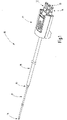
- a cryoprobe 10 is illustrated which is set up for endoscopic use.
- the cryoprobe 10 has a fluid connector 11 with connector pins 12, 13, 14, via which liquid or gaseous fluids are discharged to and from the cryoprobe 10.
- a coaxial fluid guide arrangement 15 leads to a fluid connection device, which is preferably formed by a connection piece 16.
- a second fluid guide arrangement 17 extends away from the connecting piece 16 in the distal direction.
- An effector for example a cryohead 18 , is arranged at the distal end of the second fluid guide arrangement 17 .
- the representation in figure 1 is not to scale - the length of the first fluid guide arrangement 15 can be up to several meters.
- the length of the second fluid guiding arrangement can also be considerable and range from a few decimeters to over a meter. The specific length depends on the desired application.
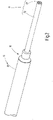
- the two fluid guide assemblies 15, 17 are coaxial assemblies, as can be seen from the figures 2 and 3 results.
- the first fluid guide arrangement 15 includes a first inner line 19 and a first outer line 20, preferably made of UV-transparent plastic.
- the inner line 19 extends through the lumen of the outer line 20, with the diameter of the lumen of the outer line 20 being significantly larger than the outer diameter of the first inner line 19.
- the inner line 19 lies with play within the lumen of the first outer line 20.
- a coaxial arrangement is also referred to when the inner line 19 is not located in the center of the outer line.
- the second fluid-guiding arrangement 17 which includes a second inner line 21 and a second outer line 22, which are arranged coaxially with one another are.
- the first inner line 19 is connected to one of the connector pins 12 to 14 of the fluid connector 11 .
- the first fluid guiding line 20 is connected to another of the connector pins 12 to 14 .
- the free flow cross sections of the first inner line 19 and the first outer line 20 are significantly larger than the free flow cross sections of the second inner line 21 and the second outer line 22.
- the outer diameter of the second fluid guide arrangement 17 is preferably significantly smaller than the outer diameter of the first fluid guide arrangement 15.
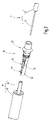
- the fluid connector goes out before assembly figure 3 as well as in the assembled state from the figures 4 and 5 out.
- the connecting piece 16 which is preferably made of UV-transparent plastic and has a socket-like section that forms an outer line socket 23 .
- This has a collar 24 which delimits an outer peripheral surface 25 ending at a collar 24 , which forms a seat for the first outer line 20 .
- the outer peripheral surface 25 can be cylindrical or, as shown, structured by having a plurality of grooves 26, preferably running in the circumferential direction, and optionally one or more ribs 27, the sawtooth profile of which allows the outer line 20 to be pushed onto the outer peripheral surface 25, but which prevents it from being pulled off .
- a radial passage 28 extends from the outer peripheral surface 25 to an axial passage opening 29, which receives the second outer pipe 22 and forms a seat for it.
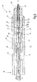
- the through-opening 29 extends up to a step 30 at which the diameter of the through-opening 29 is reduced somewhat.
- the reduced inner diameter is significantly larger than the outer diameter of the second inner line 21, preferably at least as large as the inner diameter of the second outer line 22.
- a capillary gap is formed between the inner surface of the passage opening 29 and the outer surface of the second outer line 22, the width of which is dimensioned such that curable adhesive filled into the passage 28 pulls into the gap formed and forms a meniscus at the distal end of the passage opening 29 , without running out.
- the second inner duct 21 protrudes from the proximal end of the second outer duct 22 and extends up to the distal end of the first inner line 19, which in turn is clearly surmounted by the first outer line 20.
- the distal end of the first inner lead 19 is received in an inner lead socket 32 which is connected to the outer lead socket 23 via one or more spacers 33 .
- the inner line socket 32 is formed by a tubular section, the inner diameter of which is slightly larger than the outer diameter of the first inner line 19.
- the tubular section of the inner line socket 32 transitions at an annular shoulder 34 into a trough section 35 which has an adhesive filling opening 36 and towards the Spacer 33 is closed by a wall 37.
- This has an opening 38 whose diameter is preferably significantly larger than the diameter of the second inner line 21 .
- the diameter of the opening 38 is preferably at least as large as the inner diameter of the annular shoulder 34.
- a particularly simple injection molding tool for producing the connecting piece 16 can be constructed as an injection molded part.
- the second inner line 21 extends through this opening 38 and through the trough section 35 and into or through the inner line socket 32.
- the inner line socket 32 at least preferably has an adhesive filling opening 39 which breaks through the wall of the tubular inner line socket 32 in the radial direction and is preferably adjacent to the adhesive filling opening 36 .
- a capillary gap is preferably formed between the inner surface of the inner line mount 32 and the outer surface of the first inner line 19, the width of which is dimensioned such that adhesive is drawn into the capillary gap without running out.
- the adhesive forms a corresponding meniscus on the proximal face of inner lead socket 32 .
- the inside diameter of the first inner line 19 and the outside diameter of the second inner line 21 are matched to one another in such a way that the preferably cylindrical annular gap formed between them in the trough section 35 receives adhesive 41 without it reaching the proximal end of the second inner line 21 or closing it.
- the diameter of the opening 38 is preferably also dimensioned such that an uncontrolled outflow of the adhesive 41 from the trough section 35 after the latter has been filled with liquid adhesive is prevented.
- the second fluid guide arrangement 17 is first introduced until the second inner line 21 protrudes through the inner line socket 32 and the second outer line 22 rests against the step 30 . Furthermore, the first fluid guide arrangement 15 is attached to the fluid connection device by pushing the first inner line 19 onto the second inner line 21 and inserting it into the inner line holder 32 up to the stop formed by the annular shoulder 34 . Adhesive 31, 40, 41 is now filled into the passage 28 and into the adhesive filling openings 36, 39. The adhesive wets the inner surface of the through opening 29 and the outer surface of the second outer line 22. In addition, the adhesive 40 wets the outer surface of the first inner line 19 and the inner surface of the inner line socket 32.
- the adhesive 41 filled in via the adhesive filling opening 36 wets the outer surface of the second inner line 21 and penetrates into the space between the two inner lines 19, 21. Further adhesive is applied to the grooves 26 or the outer peripheral surface 25, after which the first outer line 20 is applied to the outer peripheral surface 25 is postponed. Then the adhesive 31, 40, 41 is caused to harden. This can preferably be done with UV radiation.
- the first outer line 20 and/or the fluid connection device ie the plastic from which this injection-molded part is made, is designed to be UV-transmissive and/or UV-light-conducting.
- the fluid connection device consists of a single plastic injection-molded part, which accommodates a coaxial first fluid guide arrangement 15 and a second fluid guide arrangement 17, which is also coaxial, and provides a plurality of adhesive reservoirs that allow the two fluid guide arrangements 15, 17 to be bonded to one another in a pressure-tight, process-reliable manner.
- the fluid connection device is characterized by a high level of functional integration in just one component, namely the connection piece 16 .
- the connecting piece 16 and the adhesive connection a mechanically tensile connection of the two fluid-guiding arrangements 15, 17 to one another is achieved.
- FIG. 12 illustrates a modified embodiment of the fluid connection device according to the invention, to which the above description applies accordingly.
- this embodiment has a barrier 42 arranged on the second inner line 21, which is held on the inner line 21 by friction and is formed, for example, by a rubber or plastic disk. During the joining process, the barrier 42 rests against the opening 38 and prevents adhesive from leaking out there during the gluing process. After the same has hardened, the barrier 42 has no function.
- FIG. 7 A further modified embodiment of the fluid connection device according to the invention is figure 7 illustrated.
- the opening 38 can be narrower than the annular shoulder 34 and also narrower than the through-opening 29 .
- the opening 38 can be designed like a funnel, ie widening conically towards the opening 29, in order to facilitate the introduction of the second inner line 21 into the connecting piece 16 on the one hand and the handling of the gluing process on the other.
- Each of the fluid connection devices described above has only a few (namely four) interfaces that have to be connected and sealed, which is preferably done by extensive gluing.
- the structure only requires a small amount of coordination in terms of matching the dimensions and dimensions of parts to one another.
- the connecting device according to the invention allows quick assembly and low assembly costs. This leads to reduced product costs due to low costs for the necessary parts. Finally, the dimensions and weight of the connecting device are reduced.
- the invention allows the use of a simple sealing and connection technique, in particular gluing (for example by means of UV-curing adhesives, the use of the capillary effect to fill the adhesive gap).
- gluing for example by means of UV-curing adhesives, the use of the capillary effect to fill the adhesive gap.
- the parts used in particular the inner lines 19, 21 and the outer lines 20, 22, are subject to lower accuracy requirements.
- the inner lines 19, 21 can be pushed far into one another in the axial direction (eg several centimeters). This also prevents adhesive from running into the open end of the second inner line 21 when the end between the two inner lines 19, 21 formed adhesive gap has a larger gap width than should ideally be provided. Again, less precise parts are required.
- plastics instead of metals allows for lower part and material costs, particularly as a result of the use of plastic injection molded parts.
- cryoprobe 11 fluid connector 12, 13, 14 connector pins 15 first fluid guide arrangement 16 Connector / fluid connector 17 second fluid guide arrangement 18 cryohead 19 first inner line 20 first outside line 21 second inner line 22 second external line 23 outdoor line socket 24 Federation 25 outer peripheral surface 26 grooves 27 rib 28 radial passage 29 axial through hole 30 step 31 adhesive 32 inner line fitting 33 spacers 34 ring shoulder 35 tub section 36 Adhesive Filling Port 37 Wall 38 opening 39 Adhesive Filling Port 40, 41 adhesive 42 barrier
Landscapes
- Health & Medical Sciences (AREA)
- Engineering & Computer Science (AREA)
- Mechanical Engineering (AREA)
- Surgery (AREA)
- Life Sciences & Earth Sciences (AREA)
- Nuclear Medicine, Radiotherapy & Molecular Imaging (AREA)
- Public Health (AREA)
- Heart & Thoracic Surgery (AREA)
- Medical Informatics (AREA)
- Molecular Biology (AREA)
- Animal Behavior & Ethology (AREA)
- General Health & Medical Sciences (AREA)
- Biomedical Technology (AREA)
- Veterinary Medicine (AREA)
- Otolaryngology (AREA)
- Physics & Mathematics (AREA)
- Electromagnetism (AREA)
- Toxicology (AREA)
- Chemical & Material Sciences (AREA)
- Chemical Kinetics & Catalysis (AREA)
- General Chemical & Material Sciences (AREA)
- Endoscopes (AREA)
- Infusion, Injection, And Reservoir Apparatuses (AREA)
- Surgical Instruments (AREA)
- Arrangements For Transmission Of Measured Signals (AREA)
Description
Die Erfindung betrifft ein Instrument oder eine Sonde mit einer Fluidverbindungseinrichtung zur Verbindung zweier Koaxialleitungen miteinander, insbesondere für Kryosonden. Außerdem betrifft die Erfindung eine mit einer erfindungsgemäßen Fluidverbindungseinrichtung ausgerüstete Kryosonde.The invention relates to an instrument or a probe with a fluid connection device for connecting two coaxial lines to one another, in particular for cryoprobes. The invention also relates to a cryoprobe equipped with a fluid connection device according to the invention.
Bei Kryosonden und anderen medizinischen Instrumenten, die mit Fluiden, zum Beispiel Flüssigkeiten oder Gasen, zu versorgen sind, müssen häufig Versorgungsleitungen an entsprechende Applikatorleitungen angeschlossen werden.In the case of cryoprobes and other medical instruments that are to be supplied with fluids, for example liquids or gases, supply lines often have to be connected to corresponding applicator lines.
Dazu beschreibt die
Dem gleichen Prinzip genügt die aus der
Solche Instrumente eignen sich für offenchirurgische Anwendungen, bei denen das Instrument am Handgriff manuell geführt wird und der Handgriffe eine Weiche bilden kann. Für laparoskopische oder endoskopische Anwendungen eignen sich diese Einrichtungen nicht.Such instruments are suitable for open surgical applications in which the instrument is guided manually by the handle and the handle can form a switch. These devices are not suitable for laparoscopic or endoscopic applications.
Aus der
Aus der
Es ist Aufgabe der Erfindung, ein Instrument mit einer Fluidverbindungseinrichtung zu schaffen, die sich zur Anwendung an endoskopisch zu verwendenden Instrumenten, Sonden oder dergleichen, eignet. Diese Aufgaben werden mit einem Instrument oder einer Sonde nach Anspruch 1 gelöst:It is the object of the invention to provide an instrument with a fluid connection device which is suitable for use on instruments, probes or the like to be used endoscopically. These tasks are solved with an instrument or a probe according to claim 1:
Die erfindungsgemäße Fluidverbindungseinrichtung bildet eine mechanische und fluiddurchlässige Verbindung zwischen einer ersten Fluidführungsanordnung und einer zweiten Fluidführungsanordnung. Diese beiden Fluidführungsanordnungen weisen gleiche oder auch, typischerweise, unterschiedliche Außendurchmesser auf. Zu jeder koaxialen Fluidführungsanordnung gehören eine Innenleitung und eine Außenleitung, wobei sich die jeweilige Innenleitung durch das innere Lumen der betreffenden Außenleitung erstreckt. Die Fluidführungsanordnung heißt auch dann "koaxial", wenn die Innenleitung in dem Lumen der Außenleitung über ihre gesamte Länge oder Teile derselben außermittig angeordnet ist, sich jedenfalls aber durch das Lumen erstreckt. Bei typischen Anwendungen strömt das Fluid in den Innenleitungen in distaler Richtung, in den Außenleitungen strömt es in proximaler Richtung und somit jedenfalls gegensätzlich. Die Strömungsrichtungen können aber auch umgekehrt sein, wobei die nachfolgende Beschreibung und Ansprüche entsprechend gelten.The fluid connection device according to the invention forms a mechanical and fluid-permeable connection between a first fluid-guiding arrangement and a second fluid-guiding arrangement. These two fluid guiding arrangements have the same or also, typically, different outside diameters. Each coaxial fluid conduit assembly includes an inner conduit and an outer conduit, with each inner conduit extending through the inner lumen of the respective outer conduit. The fluid guiding arrangement is also called "coaxial" when the inner line is arranged eccentrically in the lumen of the outer line over its entire length or parts thereof, but in any case extends through the lumen. In typical applications, the fluid in the inner lines flows in the distal direction, in the outer lines it flows in the proximal direction and thus in any case in the opposite direction. However, the directions of flow can also be reversed, with the following description and claims applying accordingly.
Bei der erfindungsgemäßen Fluidverbindungseinrichtung ragt bei der ersten Fluidführungsanordnung das Ende der Außenleitung über das Ende der Innenleitung hinaus. Die zweite Fluidführungsanordnung ist bezüglich der ersten Fluidführungsanordnung distal angeordnet. Bei der zweiten Fluidführungsanordnung ragt das proximale Ende der Innenleitung aus dem proximalen Ende der Außenleitung heraus. Die Enden der beiden Außenleitungen sind jeweils mit einer Außenleitungsfassung verbunden.In the fluid connection device according to the invention, the end of the outer line protrudes beyond the end of the inner line in the first fluid guide arrangement. The second fluid guide arrangement is arranged distally with respect to the first fluid guide arrangement. In the case of the second fluid guiding arrangement, the proximal end of the inner line protrudes from the proximal end of the outer line. The ends of the two external lines are each connected to an external line socket.
Vorzugsweise sind die Enden der Innenleitungen direkt miteinander verbunden und in einer Innenleitungsfassung gehalten. Die Innenleitungsfassung und die Außenleitungsfassung sind miteinander über einen Abstandshalter verbunden. Die Außenleitungsfassung, die Innenleitungsfassung und der Abstandshalter bilden ein Verbindungsstück, das als einstückiges Kunststoff-Spritzgussteil ausgebildet sein kann.The ends of the inner lines are preferably connected directly to one another and held in an inner line socket. The inner-wire socket and the outer-wire socket are connected to each other via a spacer. The outer line socket, the inner line socket and the spacer form a connection piece which can be designed as a one-piece plastic injection molded part.
Die Innenleitungsfassung und die Außenleitungsfassung sind axial voneinander distanziert. Gleichfalls ist die Überlappung der Enden der Außenleitungen von der Überlappung der Enden der Innenleitungen voneinander axial distanziert.The inner-line socket and the outer-line socket are axially spaced from each other. Likewise, the overlap of the ends of the outer leads is spaced axially apart from the overlap of the ends of the inner leads.
Diese Anordnung baut äußerst schlank und ist insbesondere zur Verbindung von Fluidführungsanordnungen mit unterschiedlichen Außendurchmessern geeignet. Vorzugsweise weist die distale, d.h. die zweite Fluidführungsanordnung einen geringeren Außendurchmesser auf, als die erste, d.h. proximale Fluidführungsanordnung. Insbesondere ermöglicht der Durchmesserunterschied einerseits eine sehr schlanke, zur Anwendung in Kathetern geeignete Bauweise für die distale Kryosonde und andererseits kann die proximale Fluidführungsanordnung einen ausreichend großen Durchmesser aufweisen, um günstige Strömungsverhältnisse, insbesondere einen niedrigen Strömungswiderstand zu ermöglichen.This arrangement is extremely slim and is particularly suitable for connecting fluid-guiding arrangements with different outside diameters. The distal, ie the second, fluid guiding arrangement preferably has a smaller outer diameter than the first, ie proximal, fluid guiding arrangement. In particular, the difference in diameter enables a very slim design for the distal cryoprobe, suitable for use in catheters, and the proximal fluid guide arrangement can have a sufficiently large diameter to enable favorable flow conditions, in particular low flow resistance.
Das erfindungsgemäße Verbindungskonzept für die beiden Fluidführungsanordnungen geht vorzugsweise davon aus, dass die Außenleitungen mittelbar über die Außenleitungsfassung und die Innenleitungen unmittelbar direkt miteinander verbunden sind. Zum Anschluss der ersten, d.h. proximalen, Rückführungsleitung weist der Außenleitungsfassung eine Außenumfangsfläche auf, die einen Sitz bildet, der die erste Außenleitung aufnimmt. Der Sitz kann strukturiert sein und dazu entsprechende Rippen, Vorsprünge, Vertiefungen und dergleichen, aufweisen. Insbesondere kann die erste Außenleitung mit der Außenumfangsfläche der Außenleitungsfassung verklebt sein. Die Verklebung erfolgt vorzugsweise durch einen Klebstoff mit extern initiierbarer Aushärtung, beispielsweise durch UV-Licht.The connection concept according to the invention for the two fluid guide arrangements is preferably based on the fact that the outer lines are connected to one another indirectly via the outer line socket and the inner lines are directly connected to one another. For connection of the first, i.e. proximal, return line, the outer line socket has an outer peripheral surface forming a seat that receives the first outer line. The seat can be structured and have corresponding ribs, projections, depressions and the like. In particular, the first outer line can be glued to the outer peripheral surface of the outer line socket. The bonding is preferably carried out using an adhesive with externally initiable curing, for example using UV light.
Der Außenleitungsfassung weist vorzugsweise eine Öffnung auf, in der die zweite, d.h. distale Außenleitung gehalten ist. Vorzugsweise ist diese Außenleitung mit der Innenfläche der Öffnung verklebt. Der Außenleitungsfassung kann einen Durchgang aufweisen, der sich von der Außenumfangsfläche bis zu der Innenfläche der Öffnung erstreckt und vorzugsweise als Klebstoffreservoir dient. Damit können beide Außenleitungen prozesstechnisch einfach, druckfest und prozesssicher durch Klebung mit der Außenleitungsfassung verbunden werden. Es wird bei der Herstellung nach dem Einstecken der zweiten Fluidführungsanordnung in die Außenleitungsfassung der Durchgang bzw. das Klebstoffreservoir mit Klebstoff gefüllt, wobei der Klebstoff durch Kapillarkräfte in den Fügespalt zwischen der zweiten Außenleitung und der Außenleitungsfassung einzieht. Dazu sind der Fügespalt und der Klebstoff so aufeinander abgestimmte, dass sich der Fügespalt durch die vorhandenen Kapillarkräfte entlang des gesamten Umfangs der Durchgangsöffnung und entlang ihrer gesamten Länge mit Klebstoff füllt.The outer line holder preferably has an opening in which the second, ie distal, outer line is held. Preferably, this outer lead is glued to the inner surface of the opening. The outer wire socket may have a passage extending from the outer peripheral surface to the inner surface of the opening and preferably serves as an adhesive reservoir. This means that both external lines can be connected to the external line socket in a process-technical simple, pressure-resistant and process-reliable manner by gluing. During production, after the second fluid guiding arrangement has been inserted into the outer line socket, the passage or the adhesive reservoir is filled with adhesive, with the adhesive being drawn into the joint gap between the second outer line and the outer line socket by capillary forces. For this purpose, the joint gap and the adhesive are matched to one another in such a way that the joint gap is filled with adhesive by the capillary forces that are present along the entire circumference of the through-opening and along its entire length.
Es kann bei der Montage so viel Klebstoff in das Klebstoffreservoir eingefüllt werden, dass der Klebstoff ungeachtet etwaiger Produktionstoleranzen jedenfalls zur Füllung des Spalts zwischen der Außenleitungsfassung und der zweiten Außenleitung genügt, was der prozesssicheren Herstellbarkeit der Klebeverbindung zugutekommt. Außerdem kann er auch die Außenumfangsfläche benetzen, so dass die auf diese Umfangsfläche aufgeschobene Außenleitung mit der Außenumfangsfläche verklebt, sobald der Klebstoff aushärtet. Alternativ kann der Klebstoff gesondert auf die Außenumfangsfläche, z.B. auf einen mit in Umfangsrichtung verlaufenden Rillen versehenen Bereich, aufgetragen werden.During assembly, enough adhesive can be filled into the adhesive reservoir that the adhesive is sufficient to fill the gap between the outer line socket and the second outer line, regardless of any production tolerances, which benefits the process-reliable manufacturability of the adhesive connection. In addition, it can also wet the outer peripheral surface, so that the outer line pushed onto this peripheral surface sticks to the outer peripheral surface as soon as the adhesive hardens. Alternatively, the adhesive may be separately applied to the outer peripheral surface, such as an area provided with circumferential grooves.
Die axiale Anordnung und die Ausdehnung der Außenleitungen sind dabei vorzugsweise so getroffen, dass sich die zweite Außenleitung mit ihrem Ende in die erste Außenleitung erstreckt, d.h. die Enden beider Außenleitungen überlappen einander. Insbesondere ist dadurch das Klebstoffreservoir zwischen der Innenfläche der ersten Fluidführungsleitung und der Außenfläche der zweiten Außenleitung angeordnet, was wiederum der prozesssicheren Herstellbarkeit der Klebeverbindung zugutekommt. Den radialen, auf Grund der Durchmesserunterschiede gegebenen Abstand zwischen den Außenleitungen überbrückt die Außenleitungsfassung.The axial arrangement and the extent of the outer lines are preferably such that the end of the second outer line extends into the first outer line, i.e. the ends of both outer lines overlap. In particular, the adhesive reservoir is thus arranged between the inner surface of the first fluid conducting line and the outer surface of the second outer line, which in turn benefits the process-reliable manufacturability of the adhesive connection. The outer cable socket bridges the radial distance between the outer cables due to the difference in diameter.
Auch die Innenleitungen der beiden Fluidführungsanordnungen sind vorzugsweise direkt miteinander verklebt, wobei sich dazu vorzugsweise die zweite Innenleitung mit ihrem proximalen Ende in das distale Ende der ersten Innenleitung hinein erstreckt, d.h. das Ende der zweiten Innenleitung ist von dem Ende der ersten Innenleitung aufgenommen. Vorzugsweise ist das distale Ende der ersten Innenleitung in einer Innenleitungsfassung gefasst, die zu dem Verbindungsstück gehört und mit der gleichfalls zu dem Abstandshalter gehörenden Außenleitungsfassung über einen Abstandshalter verbunden ist.The inner lines of the two fluid guide arrangements are also preferably glued directly to one another, with the second inner line preferably extending with its proximal end into the distal end of the first inner line, ie the end of the second inner line is accommodated by the end of the first inner line. Preferably, the distal end of the first inner line is held in an inner line socket that belongs to the connector and also to the spacer associated external cable socket is connected via a spacer.
Die Innenleitungsfassung weist zur Aufnahme der ersten Innenleitung einen rohrförmigen Sitz auf, der mit einer vorzugsweise radial orientierten Klebstoffeinfüllöffnung versehen ist, die mit der Außenfläche der ersten Innenleitung in Verbindung steht. Hier eingefüllter Klebstoff verbindet den rohrförmigen Sitz mit der Außenfläche der ersten Innenleitung, indem er in einen Kapillarspalt eintritt, der zwischen dem rohrartigen Sitz der Innenleitungsfassung und der Innenleitung ausgebildet ist.For receiving the first inner line, the inner line socket has a tubular seat which is provided with a preferably radially oriented adhesive filling opening which communicates with the outer surface of the first inner line. Adhesive filled here bonds the tubular seat to the outer surface of the first inner duct by entering a capillary gap formed between the tubular seat of the inner duct socket and the inner duct.
Vorzugsweise weist die Innenleitungsfassung eine zweite Klebstoffeinfüllöffnung auf. Diese wird z.B. von dem Rand einer klebstoffaufnehmenden Wanne gebildet, durch die sich die zweite Innenleitung hindurch erstreckt. Diese Wanne ist dem rohrartigen Sitz benachbart und auf der der Außenleitungsfassung zugewandten Seite der Innenleitungsfassung angeordnet. Die Wanne bildet ein Klebstoffreservoir, von dem aus Klebstoff in einen Zwischenraum eindringen kann, der zwischen der Außenfläche der zweiten Innenleitung und der Innenfläche der ersten Innenleitung gebildet ist. Vorzugsweise ist die Weite des Spalts so bemessen, dass sich ein Kapillarspalt bildet, in den der Klebstoff eindringen kann bzw. eingezogen wird. Die Herstellung der Klebeverbindung zwischen den beiden Innenleitungen ist auf diese Weise einfach und prozesssicher möglich, indem nach dem Einstecken der Innenleitungen in den Verbindungskörper Klebstoff in die Klebstoffeinfüllöffnungen eingefüllt wird.Preferably, the inner-line socket has a second adhesive filling opening. This is formed, for example, by the edge of an adhesive-receiving trough through which the second inner line extends. This trough is adjacent to the tubular seat and is arranged on the side of the inner pipe socket facing the outer pipe socket. The trough forms an adhesive reservoir from which adhesive can penetrate into a gap formed between the outer surface of the second inner duct and the inner surface of the first inner duct. The width of the gap is preferably dimensioned such that a capillary gap is formed into which the adhesive can penetrate or is drawn. In this way, the production of the adhesive connection between the two inner lines is possible in a simple and process-reliable manner, in that adhesive is filled into the adhesive filling openings after the inner lines have been inserted into the connecting body.
Die Innenleitungsfassung ist mit der Außenleitungsfassung vorzugsweise durch einen Abstandshalter verbunden, der einen Abstand zwischen der Außenleitungsfassung und der der Innenleitungsfassung schafft. Durch diesen Abstand wird eine Fluidverbindung zwischen den beiden Außenleitungen ermöglicht. Dieses Konzept gestattet die Herstellung des Verbindungsstücks ohne Hinterschneidungen, so dass es als besonders einfach zu fertigendes Spritzgussteil aus Kunststoff gefertigt werden kann.The inner-line socket is preferably connected to the outer-line socket by a spacer that creates a distance between the outer-line socket and that of the inner-line socket. This spacing enables fluid communication between the two outer lines. This concept allows the connection piece to be made without undercuts, so that it can be manufactured as a particularly easy-to-manufacture injection molded part made of plastic.
Weitere Einzelheiten vorteilhafter Ausführungsformen der Erfindung sind Gegenstand der Zeichnung oder der Beschreibung. Die dort Einzelmerkmale der beschriebenen Ausführungsformen können losgelöst vom Gesamtzusammenhang erfinderische Bedeutung haben. Es zeigen:
-
Figur 1 eine erfindungsgemäße Kryosonde in stark verkürzter perspektivischer Darstellung mit einer Fluidverbindungseinrichtung zwischen dem distalen Sondenteil und der proximalen Fluidzuführung, -
Figur 2 die Fluidverbindungseinrichtung der Kryosonde nachFigur 1 , in einer perspektivischen Darstellung aus einer anderen Blickrichtung, -
Figur 3 die Fluidverbindungseinrichtung nachFigur 2 , vor der Montage, in einer Explosionsdarstellung, -
Figur 4 die Fluidverbindungseinrichtung nach den Figuren 2 und 3, in einer teilweise geschnittenen perspektivischen Ansicht, -
Figur 5 die Fluidverbindungseinrichtung nach den Figuren 2 bis 4 im Längsschnitt und -
Figuren 6 und7 abgewandelte Ausführungsformen der erfindungsgemäßen Fluidverbindungseinrichtung, jeweils im Längsschnitt.
-
figure 1 a cryoprobe according to the invention in a greatly shortened perspective view with a fluid connection device between the distal probe part and the proximal fluid supply, -
figure 2 the fluid connector of the cryoprobefigure 1 , in a perspective view from a different perspective, -
figure 3 the fluid connection devicefigure 2 , before assembly, in an exploded view, -
figure 4 the fluid connection device according to Figures 2 and 3, in a partially sectioned perspective view, -
figure 5 the fluid connection device according to Figures 2 to 4 in longitudinal section and -
figures 6 and7 modified embodiments of the fluid connection device according to the invention, each in longitudinal section.
In
Die beiden Fluidführungsanordnungen 15, 17 sind Koaxialanordnungen, wie sich aus den
Entsprechendes gilt für die zweite Fluidführungsanordnung 17, zu der eine zweite Innenleitung 21 und eine zweite Außenleitung 22 gehören, die koaxial zueinander angeordnet sind. Dies bedeutet, dass sich die zweite Innenleitung 21 durch das Lumen der zweiten Außenleitung 22 erstreckt, ohne dass sie dabei genau mittig verlaufen müsste. Zwischen der Außenfläche der zweiten Innenleitung 21 und der Innenfläche der zweiten Außenleitung 22 ist ein Abstand gegeben, so dass der vorhandene Ringraum zur Fluidrückführung dienen kann.The same applies to the second fluid-guiding
Die erste Innenleitung 19 ist mit einem der Steckerpins 12 bis 14 des Fluidsteckers 11 verbunden. Die erste Fluidführungsleitung 20 ist mit einem anderen der Steckerpins 12 bis 14 verbunden. Die freien Strömungsquerschnitte der ersten Innenleitung 19 und der ersten Außenleitung 20 sind wesentlich größer als die freien Strömungsquerschnitte der zweiten Innenleitung 21 und der zweiten Außenleitung 22. Ebenso ist der Außendurchmesser der zweiten Fluidführungsanordnung 17 vorzugsweise wesentlich geringer als der Außendurchmesser der ersten Fluidführungsanordnung 15.The first
Die Fluidverbindungseinrichtung geht vor der Montage aus
Von der Außenumfangsfläche 25 ausgehend erstreckt sich ein radialer Durchgang 28 zu einer axialen Durchgangsöffnung 29, die die zweite Außenleitung 22 und einen Sitz für diese bildet aufnimmt. Die Durchgangsöffnung 29 erstreckt sich bis zu einer Stufe 30, bei der sich der Durchmesser der Durchgangsöffnung 29 etwas verringert. Der verringerte Innendurchmesser ist jedoch wesentlich größer als der Außendurchmesser der zweiten Innenleitung 21, vorzugsweise mindestens so groß, wie der Innendurchmesser der zweiten Außenleitung 22. In montiertem Zustand liegt die zweite Außenleitung 22 mit ihrer proximalen Stirnfläche an dieser Stufe an und die zweite Innenleitung erstreckt sich mit radialem Spiel durch die Durchgangsöffnung 29.A
Zwischen der Innenfläche der Durchgangsöffnung 29 und der Außenfläche der zweiten Außenleitung 22 ist ein Kapillarspalt ausgebildet, dessen Weite so bemessen ist, dass sich in den Durchgang 28 eingefüllter aushärtbarer Klebstoff in den gebildeten Spalt zieht und an dem stirnseitigen distalen Ende der Durchgangsöffnung 29 einen Meniskus bildet, ohne auszulaufen.A capillary gap is formed between the inner surface of the
Wie ersichtlich, ist die Stufe 30 aus distaler Richtung gesehen jenseits des Durchgangs 28 angeordnet, so dass der Durchgang 28 von der Innenseite der ersten Außenleitung 20 ausgeht und sich bis zu der Außenseite der zweiten Außenleitung 22 erstreckt. Der Durchgang 28 ist zwischen der Stufe 30 und dem Bund 24 angeordnet. Mit anderen Worten, die zweite Außenleitung 22 steckt mit ihrem Ende in der ersten Außenleitung 20. In den Durchgang 28 eingefüllter Klebstoff 31 benetzt auch die Außenumfangsfläche 25 und gegebenenfalls die Rillen 26, so dass in gefügtem Zustand eine Klebeverbindung zwischen der ersten Außenleitung 20 und der zweiten Rückführungsleitung 22 unter Vermittlung der Außenleitungsfassung 23 der Fluidverbindungseinrichtung 16 gebildet ist.As can be seen, the
Die zweite Innenleitung 21 ragt aus dem proximalen Ende der zweiten Außenleitung 22 heraus und erstreckt sich bis in das distale Ende der ersten Innenleitung 19 hinein, das seinerseits von der ersten Außenleitung 20 deutlich überragt wird. Das distale Ende der ersten Innenleitung 19 ist von einer Innenleitungsfassung 32 aufgenommen, die über einen oder mehrere Abstandshalter 33 mit der Außenleitungsfassung 23 verbunden ist.The second
Die Innenleitungsfassung 32 wird durch einen rohrartigen Abschnitt gebildet, dessen Innendurchmesser geringfügig größer ist als der Außendurchmesser der ersten Innenleitung 19. Der rohrförmige Abschnitt der Innenleitungsfassung 32 geht an einer Ringschulter 34 in einem Wannenabschnitt 35 über, der eine Klebstoffeinfüllöffnung 36 aufweist und in Richtung zu dem Abstandshalter 33 durch eine Wand 37 abgeschlossen ist. Diese weist eine Öffnung 38 auf, deren Durchmesser vorzugsweise deutlich größer als der Durchmesser der zweiten Innenleitung 21 ist. Vorzugsweise ist der Durchmesser der Öffnung 38 wenigstens so groß wie der innere Durchmesser der Ringschulter 34. Dadurch lässt sich ein besonders einfaches Spritzgusswerkzeug zur Herstellung des Verbindungsstücks 16 als Spritzgussteil konstruieren. Die zweite Innenleitung 21 erstreckt sich durch diese Öffnung 38 und durch den Wannenabschnitt 35 sowie in oder durch die Innenleitungsfassung 32.The
Die Innenleitungsfassung 32 weist zumindest vorzugsweise eine Klebstoffeinfüllöffnung 39 auf, die die Wandung der rohrförmigen Innenleitungsfassung 32 in Radialrichtung durchbricht und der Klebstoffeinfüllöffnung 36 vorzugsweise benachbart ist. Zwischen der Innenfläche der Innenleitungsfassung 32 und der Außenfläche der ersten Innenleitung 19 ist vorzugsweise ein Kapillarspalt ausgebildet, dessen Weite so bemessen ist, dass Klebstoff in den Kapillarspalt eingezogen wird, ohne auszulaufen. Vorzugsweise bildet der Klebstoff an der proximalen Stirnfläche der Innenleitungsfassung 32 einen entsprechenden Meniskus. Ebenso sind der Innendurchmesser der ersten Innenleitung 19 und der Außendurchmesser der zweiten Innenleitung 21 so aufeinander abgestimmt, dass der zwischen ihnen ausgebildete, vorzugsweise zylindrische Ringspalt in dem Wannenabschnitt 35 vorhanden Klebstoff 41 aufnimmt, ohne dass dieser das proximale Ende der zweiten Innenleitung 21 erreicht oder diese verschließt.The
Die Öffnung 38 ist vorzugsweise ebenfalls von ihrem Durchmesser her so bemessen, dass ein unkontrolliertes Ausfließen des Klebstoffs 41 aus dem Wannenabschnitt 35 nach Befüllung desselben mit flüssigem Klebstoff unterbleibt.The diameter of the
Die insoweit beschriebene Fluidverbindungseinrichtung 16 wird wie folgt wie nachfolgend mit Bezug auf die
In die Fluidverbindungseinrichtung nach
Nach Aushärtung des Klebstoffs ist eine dauerhafte feste druckdichte Verbindung zwischen der ersten Fluidführungsanordnung 15 und der zweiten Fluidführungsanordnung 17 gebildet.After the adhesive has hardened, a permanent, firm, pressure-tight connection is formed between the first
Die erfindungsgemäße Fluidverbindungseinrichtung besteht aus einem einzigen Kunststoff-Spritzgussteil, das eine koaxiale erste Fluidführungsanordnung 15 sowie eine ebenfalls koaxiale zweite Fluidführungsanordnung 17 aufnimmt und mehrere Klebstoffreservoirs bereitstellt, die eine druckfeste prozesssichere Verklebung der beiden Fluidführungsanordnungen 15, 17 miteinander gestatten. Die Fluidverbindungseinrichtung zeichnet sich durch eine hohe Funktionsintegration in nur einem Bauteil, nämlich dem Verbindungsstück 16 aus. Außerdem wird mit Hilfe des Verbindungsstücks 16 und der Klebeverbindung wird mechanisch zugfeste Verbindung der beiden Fluidführungsanordnungen 15, 17 miteinander erreicht.The fluid connection device according to the invention consists of a single plastic injection-molded part, which accommodates a coaxial first
Eine weiter abgewandelte Ausführungsform der erfindungsgemäßen Fluidverbindungseinrichtung ist in
Jede der vorbeschriebenen Fluidverbindungseinrichtungen weist nur wenige (nämlich vier) Schnittstellen auf, die verbunden und abgedichtet werden müssen, was vorzugsweise durch flächenhafte Verklebung erfolgt. Der Aufbau erfordert lediglich einen geringen Abstimmungsbedarf hinsichtlich der Abstimmung von Abmessungen und Maßen von Teilen aufeinander. Außerdem gestattet die erfindungsgemäße Verbindungseinrichtung eine schnelle Montage und geringen Montageaufwand. Die führt zu verminderten Produktkosten durch geringen Kosten für die nötigen Teile. Schließlich sind die Maße und das Gewicht der Verbindungseinrichtung verringert.Each of the fluid connection devices described above has only a few (namely four) interfaces that have to be connected and sealed, which is preferably done by extensive gluing. The structure only requires a small amount of coordination in terms of matching the dimensions and dimensions of parts to one another. In addition, the connecting device according to the invention allows quick assembly and low assembly costs. This leads to reduced product costs due to low costs for the necessary parts. Finally, the dimensions and weight of the connecting device are reduced.
Die Erfindung gestattet die Verwendung einer einfachen Dichtungs- und Verbindungstechnik, insbesondere Verklebung (z.B. mittels UV-aushärtender Klebstoffe, die Ausnutzung des Kapillareffekts zur Füllung der Klebespalte). Durch die Verbindung und Abdichtung durch Verkleben können Toleranzen ausgeglichen werden, weswegen an die verwendeten Teile, insbesondere die Innenleitungen 19, 21 und die Außenleitungen 20, 22 geringere Genauigkeitsanforderungen zu stellen sind. Z.B. können die Innenleitungen 19, 21 in Axialrichtung weit ineinandergeschoben sein (z.B. mehrere Zentimeter). Dadurch wird ein Einlaufen von Klebstoff in das offene Ende der zweiten Innenleitung 21 auch dann vermieden, wenn der zwischen den beiden Innenleitungen 19, 21 gebildete Klebespalt eine größere Spaltweite aufweist, als idealerweise vorzusehen. Wiederum, es werden weniger genaue Teile benötigt. Außerdem werden durch die Dichtung durch Verkleben keine Teile zum z.B. Pressen von Dichtelementen benötigt. Auch entfallen gesonderte Dichtelemente, wie O-Ringe oder dergleichen. Durch die Verwendung von vordefinierten Klebewanne (Klebstoffreservoirs), kann der Klebeprozess automatisiert und prozesssicher gestaltet werden. Mit Hilfe des Klebstoffes wird der Gaszulauf gegenüber dem Gasrücklauf bis zu 130 bar abgedichtet.The invention allows the use of a simple sealing and connection technique, in particular gluing (for example by means of UV-curing adhesives, the use of the capillary effect to fill the adhesive gap). By connecting and sealing by gluing, tolerances can be compensated, which is why the parts used, in particular the
Die Verwendung von Kunststoffen anstelle von Metallen ermöglicht geringere Teilekosten- und Materialkosten, insbesondere infolge der Nutzung von Kunststoff-Spritzgussteilen.The use of plastics instead of metals allows for lower part and material costs, particularly as a result of the use of plastic injection molded parts.
Claims (14)
- Instrument or probe particularly for endoscopic use,having a first coaxial fluid conveying arrangement (15) with a first outer diameter that comprises a first inner line (19) and a first outer line (20), the end of which extends beyond the end of the first inner line (19),having a second coaxial fluid conveying arrangement (17) with a second outer diameter that comprises a second outer line (22) and a second inner line (21),wherein the end of the second inner line (21) extends beyond the end of the second outer line (22) and extends into the first inner line (19) and is connected therewith,characterized by a connection piece (16) for connection of the first fluid conveying arrangement (15) with the second fluid conveying arrangement (17),wherein the ends of the two outer lines (20, 22) are connected with one another by means of an outer line socket (23) of the connection piece (16),wherein the outer line socket (23) comprises an outer peripheral surface (25) on which the first outer line (20) is held.
- Instrument according to claim 1, characterized in that the first outer line (20) is glued to the outer peripheral surface (25) of the outer line socket (23).
- Instrument according to any of the preceding claims, characterized in that the outer line socket (23) comprises an opening (29) in which the second outer line (22) is held.
- Instrument according to claim 4, characterized in that the second outer line (22) is glued to an inner surface of the opening (29).
- Instrument according to any of the claims 2 or 3 and 5, characterized in that the outer line (23) comprises a passage (28) that extends from the outer peripheral surface (25) to the inner surface of the opening (29).
- Instrument according to claim 5, characterized in that the passage (28) is an adhesive reservoir.
- Instrument according to any of the preceding claims, characterized in that the end of the second outer line (22) extends into the first outer line (20).
- Instrument according to any of the preceding claims, characterized in that the first inner line (19) and the second inner line (21) are glued to one another.
- Instrument according to any of the preceding claims, characterized in that the connection piece (16) comprises an inner line socket (32) in which the first inner line (19) is held.
- Instrument according to claim 9, characterized in that the inner line socket (32) comprises a seat for the first inner line (19), wherein the seat comprises an adhesive insertion opening (39) in communication with the outer surface of the first inner line (19) and is configured as adhesive reservoir.
- Instrument according to any of the preceding claims, characterized in that the connection piece (16) comprises an inner line socket (32) in which the second inner line (21) is held.
- Instrument according to claim 11, characterized in that the inner line socket (32) comprises an adhesive receiving space (35) through which the second inner line (21) extends and which is in communication with the first inner line (19).
- Instrument according to claim 9 or 11, characterized in that the connection piece (16) comprises a spacer (33) that is connected to the inner line socket (32).
- Instrument according to any of the preceding claims, characterized in that the instrument is a cryoprobe (10) .
Priority Applications (8)
| Application Number | Priority Date | Filing Date | Title |
|---|---|---|---|
| EP17155740.8A EP3360496B1 (en) | 2017-02-10 | 2017-02-10 | Fluid connection device and cryosurgical probe having same |
| PL17155740T PL3360496T3 (en) | 2017-02-10 | 2017-02-10 | Fluid connection device and cryosurgical probe having same |
| BR102017027706-2A BR102017027706B1 (en) | 2017-02-10 | 2017-12-21 | FLUID CONNECTION SYSTEM AND CRYOGENIC SURGICAL PROBE WITH THE SAME |
| JP2018010714A JP7045203B2 (en) | 2017-02-10 | 2018-01-25 | Fluid connection system and freezing probe using it |
| KR1020180009736A KR102471300B1 (en) | 2017-02-10 | 2018-01-26 | Fluid connecting system and cryoprobe with same |
| US15/891,901 US10864032B2 (en) | 2017-02-10 | 2018-02-08 | Fluid connecting system and cryoprobe with same |
| RU2018105019A RU2751967C2 (en) | 2017-02-10 | 2018-02-09 | Flow communication device and cryoprobe with such flow communication device |
| CN201810135300.9A CN108403205B (en) | 2017-02-10 | 2018-02-09 | Fluid connection system and cryoprobe with fluid connection system |
Applications Claiming Priority (1)
| Application Number | Priority Date | Filing Date | Title |
|---|---|---|---|
| EP17155740.8A EP3360496B1 (en) | 2017-02-10 | 2017-02-10 | Fluid connection device and cryosurgical probe having same |
Publications (2)
| Publication Number | Publication Date |
|---|---|
| EP3360496A1 EP3360496A1 (en) | 2018-08-15 |
| EP3360496B1 true EP3360496B1 (en) | 2022-04-06 |
Family
ID=58043902
Family Applications (1)
| Application Number | Title | Priority Date | Filing Date |
|---|---|---|---|
| EP17155740.8A Active EP3360496B1 (en) | 2017-02-10 | 2017-02-10 | Fluid connection device and cryosurgical probe having same |
Country Status (7)
| Country | Link |
|---|---|
| US (1) | US10864032B2 (en) |
| EP (1) | EP3360496B1 (en) |
| JP (1) | JP7045203B2 (en) |
| KR (1) | KR102471300B1 (en) |
| CN (1) | CN108403205B (en) |
| PL (1) | PL3360496T3 (en) |
| RU (1) | RU2751967C2 (en) |
Citations (1)
| Publication number | Priority date | Publication date | Assignee | Title |
|---|---|---|---|---|
| EP1433990A1 (en) * | 2002-12-26 | 2004-06-30 | Calsonic Kansei Corporation | Flexible hose |
Family Cites Families (39)
| Publication number | Priority date | Publication date | Assignee | Title |
|---|---|---|---|---|
| US3439680A (en) | 1965-04-12 | 1969-04-22 | Univ Northwestern | Surgical instrument for cataract removal |
| US3536075A (en) | 1967-08-01 | 1970-10-27 | Univ Northwestern | Cryosurgical instrument |
| US3841671A (en) * | 1973-10-30 | 1974-10-15 | Gen Motors Corp | Coaxial fluid lines with plug-in connector assemblies |
| CN1038220A (en) * | 1988-03-07 | 1989-12-27 | 利奥卡有限公司 | Band is the minimal type gabarit angioplasty balloon catheter of the removable guide line of control easily |
| US4884573A (en) * | 1988-03-07 | 1989-12-05 | Leocor, Inc. | Very low profile angioplasty balloon catheter with capacity to use steerable, removable guidewire |
| CN1030559C (en) | 1988-06-08 | 1995-12-27 | 程慧雄 | Radiation-type vacuum continuous filter using internal filtering in rotating drum |
| US5047045A (en) * | 1989-04-13 | 1991-09-10 | Scimed Life Systems, Inc. | Multi-section coaxial angioplasty catheter |
| US5344395A (en) * | 1989-11-13 | 1994-09-06 | Scimed Life Systems, Inc. | Apparatus for intravascular cavitation or delivery of low frequency mechanical energy |
| US5334162A (en) * | 1993-03-15 | 1994-08-02 | Eli Lilly And Company | Cartridge assembly for a lyophilized compound forming a disposable portion of an injector pen and method for same |
| US5916213A (en) | 1997-02-04 | 1999-06-29 | Medtronic, Inc. | Systems and methods for tissue mapping and ablation |
| US5846235A (en) | 1997-04-14 | 1998-12-08 | Johns Hopkins University | Endoscopic cryospray device |
| US20030028182A1 (en) * | 1999-04-21 | 2003-02-06 | Cryocath Technologies Inc. | Cryoablation catheter handle |
| DE10128701B4 (en) * | 2001-06-07 | 2005-06-23 | Celon Ag Medical Instruments | probe assembly |
| US6767346B2 (en) | 2001-09-20 | 2004-07-27 | Endocare, Inc. | Cryosurgical probe with bellows shaft |
| US6858025B2 (en) * | 2002-08-06 | 2005-02-22 | Medically Advanced Designs, Llc | Cryo-surgical apparatus and method of use |
| US7189228B2 (en) | 2003-06-25 | 2007-03-13 | Endocare, Inc. | Detachable cryosurgical probe with breakaway handle |
| FI20045456A (en) * | 2004-11-24 | 2006-05-25 | Wallac Oy | Punching tool for taking a biological test piece |
| CA2597586C (en) * | 2005-02-14 | 2014-12-09 | Gilero, Llc | Valved fluid connector |
| CN100408001C (en) | 2005-04-14 | 2008-08-06 | 北京库蓝医疗设备有限公司 | Disposable freezing probe |
| US20070191732A1 (en) | 2006-02-10 | 2007-08-16 | Voegele James W | Cryogenic probe |
| US20070241560A1 (en) * | 2006-04-18 | 2007-10-18 | Malone David S | Coaxial quick connector |
| CN102065785B (en) | 2008-06-11 | 2013-06-12 | 奥瑞舒科技公司 | Cryo-surgical systems and methods of using the same |
| US8251987B2 (en) | 2008-08-28 | 2012-08-28 | Vivant Medical, Inc. | Microwave antenna |
| US9332973B2 (en) * | 2008-10-01 | 2016-05-10 | Covidien Lp | Needle biopsy device with exchangeable needle and integrated needle protection |
| DE202009018056U1 (en) * | 2009-04-16 | 2010-12-30 | Erbe Elektromedizin Gmbh | Endoscopic surgical instrument |
| US20130207383A1 (en) * | 2009-12-15 | 2013-08-15 | Georg Fischer Llc | Containment Pipe Fittings and Methods |
| US9023033B2 (en) | 2010-08-04 | 2015-05-05 | St. Jude Medical, Atrial Fibrillation Division, Inc. | Magnetically guided catheters |
| US8986303B2 (en) | 2010-11-09 | 2015-03-24 | Biosense Webster, Inc. | Catheter with liquid-cooled control handle |
| WO2012162829A1 (en) | 2011-05-27 | 2012-12-06 | Colibri Technologies Inc. | Medical probe with fluid rotary joint |
| US8992413B2 (en) | 2011-05-31 | 2015-03-31 | Covidien Lp | Modified wet tip antenna design |
| CN105705108B (en) | 2013-11-01 | 2017-12-01 | C2治疗公司 | Low temperature sacculus ablation system |
| US10463417B2 (en) | 2014-09-17 | 2019-11-05 | Medtronic Cryocath Lp | Universal adaptor for gas scavenging systems |
| CN204797985U (en) | 2015-07-09 | 2015-11-25 | 宁波胜杰康生物科技有限公司 | Novel pipe is melted in tumour refrigeration |
| US10449332B2 (en) * | 2015-08-05 | 2019-10-22 | Biosense Webster (Israel) Ltd. | Guide wire luer hub |
| CN105943159B (en) | 2016-05-16 | 2019-07-23 | 安隽医疗科技(南京)有限公司 | A kind of adjustable water filling ablating electrode needle |
| US20170336008A1 (en) * | 2016-05-17 | 2017-11-23 | Q Holding Company | Tubing and junction assembly and method of making the same |
| CN105852932B (en) * | 2016-06-23 | 2018-01-19 | 天津大学 | A kind of fluid-operated plaque within blood vessels remove device |
| CN106264721B (en) | 2016-08-29 | 2019-01-11 | 安隽医疗科技(南京)有限公司 | A kind of SAPMAC method ablation needle system |
| CN106264707B (en) | 2016-09-28 | 2018-08-21 | 康沣生物科技(上海)有限公司 | Cryoablation quick coupling |
-
2017
- 2017-02-10 EP EP17155740.8A patent/EP3360496B1/en active Active
- 2017-02-10 PL PL17155740T patent/PL3360496T3/en unknown
-
2018
- 2018-01-25 JP JP2018010714A patent/JP7045203B2/en active Active
- 2018-01-26 KR KR1020180009736A patent/KR102471300B1/en active IP Right Grant
- 2018-02-08 US US15/891,901 patent/US10864032B2/en active Active
- 2018-02-09 CN CN201810135300.9A patent/CN108403205B/en active Active
- 2018-02-09 RU RU2018105019A patent/RU2751967C2/en active
Patent Citations (1)
| Publication number | Priority date | Publication date | Assignee | Title |
|---|---|---|---|---|
| EP1433990A1 (en) * | 2002-12-26 | 2004-06-30 | Calsonic Kansei Corporation | Flexible hose |
Also Published As
| Publication number | Publication date |
|---|---|
| JP7045203B2 (en) | 2022-03-31 |
| BR102017027706A8 (en) | 2023-03-28 |
| RU2018105019A (en) | 2019-08-09 |
| US10864032B2 (en) | 2020-12-15 |
| KR20180092835A (en) | 2018-08-20 |
| RU2018105019A3 (en) | 2020-12-15 |
| KR102471300B1 (en) | 2022-11-29 |
| US20180228526A1 (en) | 2018-08-16 |
| RU2751967C2 (en) | 2021-07-21 |
| BR102017027706A2 (en) | 2018-11-21 |
| PL3360496T3 (en) | 2022-06-06 |
| JP2018126502A (en) | 2018-08-16 |
| CN108403205A (en) | 2018-08-17 |
| CN108403205B (en) | 2021-08-17 |
| EP3360496A1 (en) | 2018-08-15 |
Similar Documents
| Publication | Publication Date | Title |
|---|---|---|
| DE3722904C2 (en) | ||
| EP2545315B1 (en) | Device for connecting a fluid-conducting channel to an adjacent component | |
| DE2601993A1 (en) | CANNULA ARRANGEMENT | |
| EP3217057B1 (en) | Device and method for fixing and sealing a pipe lead through in a wall passage of a building wall | |
| EP3846697B1 (en) | Medical instrument for introducing a therapeutic substance into a cavity in a targeted manner, and tool for same | |
| DE3629858C2 (en) | ||
| DE29516077U1 (en) | Spraying device | |
| EP3360496B1 (en) | Fluid connection device and cryosurgical probe having same | |
| DE102017119704B4 (en) | Line coupling and container herewith | |
| DE102011082470A1 (en) | Fitting structure of connection assembly of measuring device for examining e.g. high performance liquid chromatography (HPLC) liquid, has capillary whose end portion dimension is adjusted with respect to that of adjacent portion | |
| DE10162455A1 (en) | Elongating method for suction hose of vacuum cleaner involves using flexible extendable hose connected between cleaner and vacuum head unit | |
| DE202007019213U1 (en) | Hose, in particular shower hose with encapsulation | |
| DE102009033365B4 (en) | check valve | |
| EP3388104B1 (en) | Flexible hose and method for its manufacture | |
| DE102011009909B4 (en) | Device for guiding a cable in a medical-technical metering device, metering device and treatment device | |
| EP3034124B1 (en) | Hose system for medical use | |
| EP3378301B1 (en) | Agricultural distributor comprising a hose connecting device for a system for transporting a gas stream | |
| DE102007030935B4 (en) | Method for connecting a pipe to a pipe socket | |
| DE10229788B4 (en) | pipette tip | |
| EP2457610A1 (en) | Luer lock adapter with catheter connection and method for producing same | |
| DE102016219083A1 (en) | Probe device for insertion into a patient's body and hose / connector assembly | |
| DE102016210653A1 (en) | Tubing / connector assembly | |
| EP3033998B1 (en) | Multi-lumen micro-catheter hose and method for producing a multi-lumen micro-catheter hose | |
| DE10251063B4 (en) | Device for placing a medical catheter according to the Seldinger method | |
| DE102017126428A1 (en) | Catheter for injection and / or application of a fluid |
Legal Events
| Date | Code | Title | Description |
|---|---|---|---|
| PUAI | Public reference made under article 153(3) epc to a published international application that has entered the european phase |
Free format text: ORIGINAL CODE: 0009012 |
|
| STAA | Information on the status of an ep patent application or granted ep patent |
Free format text: STATUS: THE APPLICATION HAS BEEN PUBLISHED |
|
| AK | Designated contracting states |
Kind code of ref document: A1 Designated state(s): AL AT BE BG CH CY CZ DE DK EE ES FI FR GB GR HR HU IE IS IT LI LT LU LV MC MK MT NL NO PL PT RO RS SE SI SK SM TR |
|
| AX | Request for extension of the european patent |
Extension state: BA ME |
|
| STAA | Information on the status of an ep patent application or granted ep patent |
Free format text: STATUS: REQUEST FOR EXAMINATION WAS MADE |
|
| 17P | Request for examination filed |
Effective date: 20181206 |
|
| RBV | Designated contracting states (corrected) |
Designated state(s): AL AT BE BG CH CY CZ DE DK EE ES FI FR GB GR HR HU IE IS IT LI LT LU LV MC MK MT NL NO PL PT RO RS SE SI SK SM TR |
|
| STAA | Information on the status of an ep patent application or granted ep patent |
Free format text: STATUS: REQUEST FOR EXAMINATION WAS MADE |
|
| STAA | Information on the status of an ep patent application or granted ep patent |
Free format text: STATUS: EXAMINATION IS IN PROGRESS |
|
| 17Q | First examination report despatched |
Effective date: 20210419 |
|
| STAA | Information on the status of an ep patent application or granted ep patent |
Free format text: STATUS: EXAMINATION IS IN PROGRESS |
|
| GRAP | Despatch of communication of intention to grant a patent |
Free format text: ORIGINAL CODE: EPIDOSNIGR1 |
|
| STAA | Information on the status of an ep patent application or granted ep patent |
Free format text: STATUS: GRANT OF PATENT IS INTENDED |
|
| RIC1 | Information provided on ipc code assigned before grant |
Ipc: B29C 65/54 20060101ALI20211105BHEP Ipc: B29C 65/48 20060101ALI20211105BHEP Ipc: B29L 23/00 20060101ALI20211105BHEP Ipc: B29C 65/14 20060101ALI20211105BHEP Ipc: B29C 65/00 20060101ALI20211105BHEP Ipc: A61M 25/00 20060101ALI20211105BHEP Ipc: A61B 18/02 20060101AFI20211105BHEP |
|
| INTG | Intention to grant announced |
Effective date: 20211214 |
|
| GRAS | Grant fee paid |
Free format text: ORIGINAL CODE: EPIDOSNIGR3 |
|
| GRAA | (expected) grant |
Free format text: ORIGINAL CODE: 0009210 |
|
| STAA | Information on the status of an ep patent application or granted ep patent |
Free format text: STATUS: THE PATENT HAS BEEN GRANTED |
|
| AK | Designated contracting states |
Kind code of ref document: B1 Designated state(s): AL AT BE BG CH CY CZ DE DK EE ES FI FR GB GR HR HU IE IS IT LI LT LU LV MC MK MT NL NO PL PT RO RS SE SI SK SM TR |
|
| REG | Reference to a national code |
Ref country code: GB Ref legal event code: FG4D Free format text: NOT ENGLISH |
|
| REG | Reference to a national code |
Ref country code: CH Ref legal event code: EP |
|
| REG | Reference to a national code |
Ref country code: AT Ref legal event code: REF Ref document number: 1480577 Country of ref document: AT Kind code of ref document: T Effective date: 20220415 |
|
| REG | Reference to a national code |
Ref country code: DE Ref legal event code: R096 Ref document number: 502017012885 Country of ref document: DE |
|
| REG | Reference to a national code |
Ref country code: IE Ref legal event code: FG4D Free format text: LANGUAGE OF EP DOCUMENT: GERMAN |
|
| REG | Reference to a national code |
Ref country code: LT Ref legal event code: MG9D |
|
| REG | Reference to a national code |
Ref country code: NL Ref legal event code: MP Effective date: 20220406 |
|
| PG25 | Lapsed in a contracting state [announced via postgrant information from national office to epo] |
Ref country code: NL Free format text: LAPSE BECAUSE OF FAILURE TO SUBMIT A TRANSLATION OF THE DESCRIPTION OR TO PAY THE FEE WITHIN THE PRESCRIBED TIME-LIMIT Effective date: 20220406 |
|
| PG25 | Lapsed in a contracting state [announced via postgrant information from national office to epo] |
Ref country code: SE Free format text: LAPSE BECAUSE OF FAILURE TO SUBMIT A TRANSLATION OF THE DESCRIPTION OR TO PAY THE FEE WITHIN THE PRESCRIBED TIME-LIMIT Effective date: 20220406 Ref country code: PT Free format text: LAPSE BECAUSE OF FAILURE TO SUBMIT A TRANSLATION OF THE DESCRIPTION OR TO PAY THE FEE WITHIN THE PRESCRIBED TIME-LIMIT Effective date: 20220808 Ref country code: NO Free format text: LAPSE BECAUSE OF FAILURE TO SUBMIT A TRANSLATION OF THE DESCRIPTION OR TO PAY THE FEE WITHIN THE PRESCRIBED TIME-LIMIT Effective date: 20220706 Ref country code: LT Free format text: LAPSE BECAUSE OF FAILURE TO SUBMIT A TRANSLATION OF THE DESCRIPTION OR TO PAY THE FEE WITHIN THE PRESCRIBED TIME-LIMIT Effective date: 20220406 Ref country code: HR Free format text: LAPSE BECAUSE OF FAILURE TO SUBMIT A TRANSLATION OF THE DESCRIPTION OR TO PAY THE FEE WITHIN THE PRESCRIBED TIME-LIMIT Effective date: 20220406 Ref country code: GR Free format text: LAPSE BECAUSE OF FAILURE TO SUBMIT A TRANSLATION OF THE DESCRIPTION OR TO PAY THE FEE WITHIN THE PRESCRIBED TIME-LIMIT Effective date: 20220707 Ref country code: FI Free format text: LAPSE BECAUSE OF FAILURE TO SUBMIT A TRANSLATION OF THE DESCRIPTION OR TO PAY THE FEE WITHIN THE PRESCRIBED TIME-LIMIT Effective date: 20220406 Ref country code: ES Free format text: LAPSE BECAUSE OF FAILURE TO SUBMIT A TRANSLATION OF THE DESCRIPTION OR TO PAY THE FEE WITHIN THE PRESCRIBED TIME-LIMIT Effective date: 20220406 Ref country code: BG Free format text: LAPSE BECAUSE OF FAILURE TO SUBMIT A TRANSLATION OF THE DESCRIPTION OR TO PAY THE FEE WITHIN THE PRESCRIBED TIME-LIMIT Effective date: 20220706 |
|
| PG25 | Lapsed in a contracting state [announced via postgrant information from national office to epo] |
Ref country code: RS Free format text: LAPSE BECAUSE OF FAILURE TO SUBMIT A TRANSLATION OF THE DESCRIPTION OR TO PAY THE FEE WITHIN THE PRESCRIBED TIME-LIMIT Effective date: 20220406 Ref country code: LV Free format text: LAPSE BECAUSE OF FAILURE TO SUBMIT A TRANSLATION OF THE DESCRIPTION OR TO PAY THE FEE WITHIN THE PRESCRIBED TIME-LIMIT Effective date: 20220406 Ref country code: IS Free format text: LAPSE BECAUSE OF FAILURE TO SUBMIT A TRANSLATION OF THE DESCRIPTION OR TO PAY THE FEE WITHIN THE PRESCRIBED TIME-LIMIT Effective date: 20220806 |
|
| REG | Reference to a national code |
Ref country code: DE Ref legal event code: R097 Ref document number: 502017012885 Country of ref document: DE |
|
| PG25 | Lapsed in a contracting state [announced via postgrant information from national office to epo] |
Ref country code: SM Free format text: LAPSE BECAUSE OF FAILURE TO SUBMIT A TRANSLATION OF THE DESCRIPTION OR TO PAY THE FEE WITHIN THE PRESCRIBED TIME-LIMIT Effective date: 20220406 Ref country code: SK Free format text: LAPSE BECAUSE OF FAILURE TO SUBMIT A TRANSLATION OF THE DESCRIPTION OR TO PAY THE FEE WITHIN THE PRESCRIBED TIME-LIMIT Effective date: 20220406 Ref country code: RO Free format text: LAPSE BECAUSE OF FAILURE TO SUBMIT A TRANSLATION OF THE DESCRIPTION OR TO PAY THE FEE WITHIN THE PRESCRIBED TIME-LIMIT Effective date: 20220406 Ref country code: EE Free format text: LAPSE BECAUSE OF FAILURE TO SUBMIT A TRANSLATION OF THE DESCRIPTION OR TO PAY THE FEE WITHIN THE PRESCRIBED TIME-LIMIT Effective date: 20220406 Ref country code: DK Free format text: LAPSE BECAUSE OF FAILURE TO SUBMIT A TRANSLATION OF THE DESCRIPTION OR TO PAY THE FEE WITHIN THE PRESCRIBED TIME-LIMIT Effective date: 20220406 Ref country code: CZ Free format text: LAPSE BECAUSE OF FAILURE TO SUBMIT A TRANSLATION OF THE DESCRIPTION OR TO PAY THE FEE WITHIN THE PRESCRIBED TIME-LIMIT Effective date: 20220406 |
|
| PLBE | No opposition filed within time limit |
Free format text: ORIGINAL CODE: 0009261 |
|
| STAA | Information on the status of an ep patent application or granted ep patent |
Free format text: STATUS: NO OPPOSITION FILED WITHIN TIME LIMIT |
|
| 26N | No opposition filed |
Effective date: 20230110 |
|
| PG25 | Lapsed in a contracting state [announced via postgrant information from national office to epo] |
Ref country code: AL Free format text: LAPSE BECAUSE OF FAILURE TO SUBMIT A TRANSLATION OF THE DESCRIPTION OR TO PAY THE FEE WITHIN THE PRESCRIBED TIME-LIMIT Effective date: 20220406 |
|
| PG25 | Lapsed in a contracting state [announced via postgrant information from national office to epo] |
Ref country code: SI Free format text: LAPSE BECAUSE OF FAILURE TO SUBMIT A TRANSLATION OF THE DESCRIPTION OR TO PAY THE FEE WITHIN THE PRESCRIBED TIME-LIMIT Effective date: 20220406 |
|
| PG25 | Lapsed in a contracting state [announced via postgrant information from national office to epo] |
Ref country code: MC Free format text: LAPSE BECAUSE OF FAILURE TO SUBMIT A TRANSLATION OF THE DESCRIPTION OR TO PAY THE FEE WITHIN THE PRESCRIBED TIME-LIMIT Effective date: 20220406 |
|
| REG | Reference to a national code |
Ref country code: CH Ref legal event code: PL |
|
| REG | Reference to a national code |
Ref country code: BE Ref legal event code: MM Effective date: 20230228 |
|
| PG25 | Lapsed in a contracting state [announced via postgrant information from national office to epo] |
Ref country code: LU Free format text: LAPSE BECAUSE OF NON-PAYMENT OF DUE FEES Effective date: 20230210 Ref country code: LI Free format text: LAPSE BECAUSE OF NON-PAYMENT OF DUE FEES Effective date: 20230228 Ref country code: CH Free format text: LAPSE BECAUSE OF NON-PAYMENT OF DUE FEES Effective date: 20230228 |
|
| REG | Reference to a national code |
Ref country code: IE Ref legal event code: MM4A |
|
| PG25 | Lapsed in a contracting state [announced via postgrant information from national office to epo] |
Ref country code: IE Free format text: LAPSE BECAUSE OF NON-PAYMENT OF DUE FEES Effective date: 20230210 |
|
| PG25 | Lapsed in a contracting state [announced via postgrant information from national office to epo] |
Ref country code: BE Free format text: LAPSE BECAUSE OF NON-PAYMENT OF DUE FEES Effective date: 20230228 |
|
| REG | Reference to a national code |
Ref country code: AT Ref legal event code: MM01 Ref document number: 1480577 Country of ref document: AT Kind code of ref document: T Effective date: 20230210 |
|
| PG25 | Lapsed in a contracting state [announced via postgrant information from national office to epo] |
Ref country code: AT Free format text: LAPSE BECAUSE OF NON-PAYMENT OF DUE FEES Effective date: 20230210 |
|
| PG25 | Lapsed in a contracting state [announced via postgrant information from national office to epo] |
Ref country code: AT Free format text: LAPSE BECAUSE OF NON-PAYMENT OF DUE FEES Effective date: 20230210 |
|
| PGFP | Annual fee paid to national office [announced via postgrant information from national office to epo] |
Ref country code: DE Payment date: 20240228 Year of fee payment: 8 Ref country code: GB Payment date: 20240220 Year of fee payment: 8 |
|
| PGFP | Annual fee paid to national office [announced via postgrant information from national office to epo] |
Ref country code: PL Payment date: 20240117 Year of fee payment: 8 Ref country code: IT Payment date: 20240222 Year of fee payment: 8 Ref country code: FR Payment date: 20240226 Year of fee payment: 8 |