JP2016531455A - Distributed remote sensing system component interface - Google Patents
Distributed remote sensing system component interface Download PDFInfo
- Publication number
- JP2016531455A JP2016531455A JP2016514156A JP2016514156A JP2016531455A JP 2016531455 A JP2016531455 A JP 2016531455A JP 2016514156 A JP2016514156 A JP 2016514156A JP 2016514156 A JP2016514156 A JP 2016514156A JP 2016531455 A JP2016531455 A JP 2016531455A
- Authority
- JP
- Japan
- Prior art keywords
- gateway
- sensing device
- communication
- distributed remote
- remote sensing
- Prior art date
- Legal status (The legal status is an assumption and is not a legal conclusion. Google has not performed a legal analysis and makes no representation as to the accuracy of the status listed.)
- Granted
Links
Images


Classifications
-
- G—PHYSICS
- G08—SIGNALLING
- G08G—TRAFFIC CONTROL SYSTEMS
- G08G1/00—Traffic control systems for road vehicles
- G08G1/14—Traffic control systems for road vehicles indicating individual free spaces in parking areas
- G08G1/141—Traffic control systems for road vehicles indicating individual free spaces in parking areas with means giving the indication of available parking spaces
- G08G1/144—Traffic control systems for road vehicles indicating individual free spaces in parking areas with means giving the indication of available parking spaces on portable or mobile units, e.g. personal digital assistant [PDA]
-
- G—PHYSICS
- G01—MEASURING; TESTING
- G01S—RADIO DIRECTION-FINDING; RADIO NAVIGATION; DETERMINING DISTANCE OR VELOCITY BY USE OF RADIO WAVES; LOCATING OR PRESENCE-DETECTING BY USE OF THE REFLECTION OR RERADIATION OF RADIO WAVES; ANALOGOUS ARRANGEMENTS USING OTHER WAVES
- G01S13/00—Systems using the reflection or reradiation of radio waves, e.g. radar systems; Analogous systems using reflection or reradiation of waves whose nature or wavelength is irrelevant or unspecified
- G01S13/88—Radar or analogous systems specially adapted for specific applications
- G01S13/91—Radar or analogous systems specially adapted for specific applications for traffic control
-
- G—PHYSICS
- G01—MEASURING; TESTING
- G01S—RADIO DIRECTION-FINDING; RADIO NAVIGATION; DETERMINING DISTANCE OR VELOCITY BY USE OF RADIO WAVES; LOCATING OR PRESENCE-DETECTING BY USE OF THE REFLECTION OR RERADIATION OF RADIO WAVES; ANALOGOUS ARRANGEMENTS USING OTHER WAVES
- G01S19/00—Satellite radio beacon positioning systems; Determining position, velocity or attitude using signals transmitted by such systems
- G01S19/01—Satellite radio beacon positioning systems transmitting time-stamped messages, e.g. GPS [Global Positioning System], GLONASS [Global Orbiting Navigation Satellite System] or GALILEO
- G01S19/03—Cooperating elements; Interaction or communication between different cooperating elements or between cooperating elements and receivers
- G01S19/10—Cooperating elements; Interaction or communication between different cooperating elements or between cooperating elements and receivers providing dedicated supplementary positioning signals
- G01S19/11—Cooperating elements; Interaction or communication between different cooperating elements or between cooperating elements and receivers providing dedicated supplementary positioning signals wherein the cooperating elements are pseudolites or satellite radio beacon positioning system signal repeaters
-
- G—PHYSICS
- G01—MEASURING; TESTING
- G01S—RADIO DIRECTION-FINDING; RADIO NAVIGATION; DETERMINING DISTANCE OR VELOCITY BY USE OF RADIO WAVES; LOCATING OR PRESENCE-DETECTING BY USE OF THE REFLECTION OR RERADIATION OF RADIO WAVES; ANALOGOUS ARRANGEMENTS USING OTHER WAVES
- G01S19/00—Satellite radio beacon positioning systems; Determining position, velocity or attitude using signals transmitted by such systems
- G01S19/38—Determining a navigation solution using signals transmitted by a satellite radio beacon positioning system
- G01S19/39—Determining a navigation solution using signals transmitted by a satellite radio beacon positioning system the satellite radio beacon positioning system transmitting time-stamped messages, e.g. GPS [Global Positioning System], GLONASS [Global Orbiting Navigation Satellite System] or GALILEO
- G01S19/42—Determining position
- G01S19/48—Determining position by combining or switching between position solutions derived from the satellite radio beacon positioning system and position solutions derived from a further system
-
- G—PHYSICS
- G08—SIGNALLING
- G08G—TRAFFIC CONTROL SYSTEMS
- G08G1/00—Traffic control systems for road vehicles
- G08G1/01—Detecting movement of traffic to be counted or controlled
- G08G1/04—Detecting movement of traffic to be counted or controlled using optical or ultrasonic detectors
-
- G—PHYSICS
- G08—SIGNALLING
- G08G—TRAFFIC CONTROL SYSTEMS
- G08G1/00—Traffic control systems for road vehicles
- G08G1/01—Detecting movement of traffic to be counted or controlled
- G08G1/042—Detecting movement of traffic to be counted or controlled using inductive or magnetic detectors
-
- G—PHYSICS
- G01—MEASURING; TESTING
- G01S—RADIO DIRECTION-FINDING; RADIO NAVIGATION; DETERMINING DISTANCE OR VELOCITY BY USE OF RADIO WAVES; LOCATING OR PRESENCE-DETECTING BY USE OF THE REFLECTION OR RERADIATION OF RADIO WAVES; ANALOGOUS ARRANGEMENTS USING OTHER WAVES
- G01S13/00—Systems using the reflection or reradiation of radio waves, e.g. radar systems; Analogous systems using reflection or reradiation of waves whose nature or wavelength is irrelevant or unspecified
- G01S13/88—Radar or analogous systems specially adapted for specific applications
- G01S13/93—Radar or analogous systems specially adapted for specific applications for anti-collision purposes
- G01S13/931—Radar or analogous systems specially adapted for specific applications for anti-collision purposes of land vehicles
- G01S2013/9314—Parking operations
-
- G—PHYSICS
- G07—CHECKING-DEVICES
- G07B—TICKET-ISSUING APPARATUS; FARE-REGISTERING APPARATUS; FRANKING APPARATUS
- G07B15/00—Arrangements or apparatus for collecting fares, tolls or entrance fees at one or more control points
- G07B15/02—Arrangements or apparatus for collecting fares, tolls or entrance fees at one or more control points taking into account a variable factor such as distance or time, e.g. for passenger transport, parking systems or car rental systems
Abstract
少なくとも1つのゲートウェイと、少なくとも1つの感知装置と、各感知装置と少なくとも1つのゲートウェイの1つとの間の共有の周波数スキームによる無線周波数通信、および、各感知装置と少なくとも1つのゲートウェイの別の1つとの間の異なる周波数スキームによる無線周波数通信を提供する通信インターフェースと、を含む分散型遠隔感知システム。Radio frequency communication according to a shared frequency scheme between at least one gateway, at least one sensing device, each sensing device and one of the at least one gateway, and another one of each sensing device and at least one gateway And a communication interface that provides radio frequency communication according to different frequency schemes between the two.
Description
[関連出願の相互参照]
本出願は、2013年5月17日に出願された米国仮特許出願第61/824,609号の利益を主張する通常出願であって、その開示内容の全ては、参照により本明細書に組み込まれる。
[Cross-reference of related applications]
This application is a conventional application claiming the benefit of US Provisional Patent Application No. 61 / 824,609, filed May 17, 2013, the entire disclosure of which is incorporated herein by reference. It is.
例示的な実施形態は、一般的に、分散型遠隔感知システムに関し、特に、所定の物理的特徴を検知するための遠隔センサを有する分散型遠隔感知システムに関する。 Exemplary embodiments generally relate to distributed remote sensing systems, and more particularly, to distributed remote sensing systems having remote sensors for sensing predetermined physical characteristics.
従来、パーキングモニタリング/感知システムが収益を上げるために使用されてきた。そのような装置には、硬貨を要求するタイマおよび巻き上げ機構が含まれる。より最近では、LCD時間インジケータを有する電子タイマを含む、電子メータが開発されている。 Traditionally, parking monitoring / sensing systems have been used to generate revenue. Such devices include a timer that requires coins and a winding mechanism. More recently, electronic meters have been developed that include an electronic timer with an LCD time indicator.
電子パーキングモニタリング装置の出現により、パーキングモニタを、関連するパーキングスペースにおける車両交通とインタラクティブにしようとする試みがなされてきた。パーキングスペースにおける車両交通に関する情報を得るための1つの方法は、パーキングモニタを車両感知装置に連結させることである。車両感知装置は、車両がパーキングスペースに入るとき、また、車両がパーキングスペースを出るときを検知することができる。車両感知装置によって収集されたデータは、分析およびユーザアカウントへの適用のために最終的に中央集中型のモニタリング場所へと転送される、中央集中型の車両パーキングスペースモニタリングの試みがなされてきた。 With the advent of electronic parking monitoring devices, attempts have been made to make the parking monitor interactive with vehicle traffic in the associated parking space. One way to obtain information about vehicle traffic in the parking space is to connect a parking monitor to the vehicle sensing device. The vehicle sensing device can detect when the vehicle enters the parking space and when the vehicle leaves the parking space. Centralized vehicle parking space monitoring attempts have been made where the data collected by the vehicle sensing device is ultimately transferred to a centralized monitoring location for analysis and application to user accounts.
一般的に、車両感知装置、および、車両感知装置と中央集中型のモニタリング場所との間の通信手段は電力供給されなければならない。物理的に引かれた電力(hard lined power)を各車両感知装置および各通信手段に供給することは非常に高価になり得る。そのため、車両感知装置および通信手段は限られた電力供給を有し得る。パーキングモニタリングシステムの構成要素はまた、故障および/または停電の影響を受ける。 In general, the vehicle sensing device and the communication means between the vehicle sensing device and the centralized monitoring location must be powered. Providing hard lined power to each vehicle sensing device and each communication means can be very expensive. Thus, the vehicle sensing device and the communication means may have a limited power supply. The components of the parking monitoring system are also subject to failure and / or power outages.
システムの構成要素の電力管理を向上させるだけでなく、システムにおける1つまたは複数の冗長性によって信頼性を向上させる分散型遠隔感知システムを有することは有利となり得る。 It may be advantageous to have a distributed remote sensing system that not only improves power management of system components, but also improves reliability through one or more redundancy in the system.
開示される実施形態の上記の態様および他の特徴が、添付の図面に関連して以下の記述において説明される。 The above aspects and other features of the disclosed embodiments are set forth in the following description with reference to the accompanying drawings.
図1は、開示される実施形態の態様に係る分散型遠隔感知システムの一部の概略図である。分散型遠隔感知システムは、車両の検知、交通パターン、車両ナビゲーション、車両位置、または、任意の適切な所定の特徴などの、特徴を感知するための遠隔センサを含んでもよい。開示される実施形態の態様が図面に関連して説明されるが、開示される実施形態の態様は、多くの形態で実施されてもよいことが理解されるべきである。さらに、任意の適切なサイズ、形状、または要素もしくは材料の種類が使用されてもよい。 FIG. 1 is a schematic diagram of a portion of a distributed remote sensing system according to aspects of the disclosed embodiment. The distributed remote sensing system may include remote sensors for sensing features, such as vehicle detection, traffic patterns, vehicle navigation, vehicle location, or any suitable predetermined feature. Although aspects of the disclosed embodiments are described with reference to the drawings, it should be understood that aspects of the disclosed embodiments may be implemented in many forms. Furthermore, any suitable size, shape, or element or material type may be used.
一の態様では、分散型遠隔感知システムは、1つまたは複数の車両パーキングスペースの使用に対して、少なくとも、モニタリングおよび/または支払請求サービスを提供し得る中央集中型の制御装置を有する、車両パーキングメータ/検知システム100であってもよい。一の態様では、車両計測システム100は、中央制御装置101と、1つまたは複数のゲートウェイ110A〜110Cと、1つまたは複数の感知装置グループ120〜122と、1つまたは複数のパーキングスペースに関する任意の適切な情報を表示するための任意の適切なディスプレイを含んでもよい1つまたは複数の周辺装置130〜132と、を含んでもよい。他の態様では、車両パーキングメータシステムは、車両パーキングメータシステム100に関連する車両パーキングスペースのモニタリングを容易にするために、任意の適切な数、および種類の構成要素を含んでもよい。中央制御装置101は、1つまたは複数のゲートウェイ110A〜110C(および1つまたは複数のゲートウェイと通信している感知装置)、および、1つまたは複数の周辺装置130〜132と、感知装置から中央制御装置へ、そして中央制御装置から周辺装置へ延びる、任意の適切な、無線または有線通信インターフェースリンクを使用して通信可能である任意の適切な制御装置であってもよい(インターフェースは、単一の通信プロトコルまたは異なる通信プロトコルの組み合わせを含んでもよい)。一の態様では、少なくとも中央制御装置101と、1つまたは複数のゲートウェイ110A〜110C(および感知装置)および/または周辺装置130〜132との間の通信は、セルラ通信リンク141、衛星通信リンク142、公衆交換電話ネットワーク145、インターネット/ワールドワイドウェブ143、イーサネット(登録商標)144、ローカルエリアネットワーク、または他の適切な、無線もしくは有線プロトコルまたは接続を介してもよい。一の態様では、感知装置グループ120〜122の中の感知装置からの通信は、ほぼリアルタイムで中央制御装置101および/または周辺装置130〜132に供給されてもよい。
In one aspect, a distributed remote sensing system includes vehicle parking having a centralized controller that can provide at least monitoring and / or billing services for use of one or more vehicle parking spaces. Meter / sensing system 100 may be used. In one aspect, the vehicle metering system 100 is optional for the
中央制御装置101は、モニタリングされる各パーキングスペースについて、パーキングスペースのユーザ、パーキングスペースの割当て/配分、到着時間、出発時間、取引料金、ユーザアカウントの貨幣残高、支払請求処理、駐車違反、パーキングスペースの利用可能性、または車両パーキングメータシステム100によってモニタリングされている各パーキングスペースの使用および支払請求に関する、他の任意の適切な情報を追跡および報告するように構成された、1つまたは複数の、プロセッサ、記憶装置および、他の任意の適切なハードウェア/ソフトウェアを含んでもよい。中央制御装置101は、ユーザに中央制御装置101へのアクセスおよび操作を可能にする、1つまたは複数のユーザインターフェースを有して構成されてもよい。一の態様では、中央制御装置101は、モニタ、キーボード、および/または他の任意の適切なユーザインターフェースを有する任意の適切な演算装置であってもよい。他の態様では、周辺装置130〜132の1つまたは複数は、任意の適切な、長距離もしくは短距離無線通信リンクおよび/または有線接続のどちらかを介して、中央制御装置101にアクセスし操作するためのユーザインターフェースを提供してもよい。中央制御装置101は、感知装置からの任意の適切なデータを受信するように構成されてもよい。感知装置から送信されたデータは、たとえば、モニタリングされているパーキングスペース、車両の検知、ならびに/または感知装置の正常性および安定/整備状態に関する任意の適切なデータを含むか、さもなければ具現化してもよい。一の態様では、中央制御装置101は、感知装置からのデータに任意の適切な処理を実行するように構成されてもよいが、他の態様では、感知装置からのデータは、たとえば中央制御装置101による処理なしに、周辺装置の1つまたは複数に表示するために構成されてもよい。
For each monitored parking space, the
一の態様では、周辺装置130〜132の1つまたは複数は、たとえば、パーキングの職員/法執行員によって使用されるための携帯ユニットであり得る執行ユニットを含んでもよい。執行ユニットは、電子的発券およびデータの取込みが分散型遠隔感知システムに統合されるように、駐車違反および/または駐車違反チケットの発行を中央制御装置101に報告するように構成されてもよい。たとえば、周辺装置130〜132を用いる警察官は、違反の通知を受けた後にパーキングスペースに到着し、法律に違反している車両があることを証明するために、パーキングスペースの目視による調査を行ってもよい。違反は周辺装置に入力されてもよく、任意に、違反車両の写真が、周辺装置によって撮影されるか、あるいは周辺装置内に読み込まれてもよい。召喚状は、周辺装置130〜132から印刷され、任意の適切な方法で車両に貼り付けられるなどの、任意の適切な方法で発行されてもよい。執行ユニットは、たとえば、パーキングの執行員によって行われた他の如何なる行動および/または他の如何なる適切な情報も、中央制御装置101に報告してもよい。そのため、周辺装置に入力された違反データは、ほぼリアルタイムで、自動的に、中央制御装置101の記憶装置のような、記憶装置に取り込まれ、保存される。理解され得るように、違反情報を分散型遠隔感知システム内に保存することは、別の違反閾値が満たされる、または新しい車両がスペースに駐車するまで、システムに、そのスペースについて警察官に警報させないようにする。別の態様では、感知装置は、消火栓の前、消防車専用車線、横断歩道、交差点などの、パーキングスペースではない場所においても使用されてもよい。分散型遠隔感知システムは、たとえば、周辺装置130〜132を介して警報が執行官へ送信されるように、車両がパーキングスペースではない場所の1つに駐車されたときには必ず、任意の適切な所定の時間枠の後に違反とするように構成されてもよい。理解できるように、分散型遠隔感知システムは、センサグループ120〜122の感知装置と併せて使用され得るカメラおよび赤外線センサなどの他の任意の適切なセンサを組み込んでもよい。カメラおよび赤外線センサからの情報は、違反および違反の履歴を追跡するために、センサグループ120〜122の感知装置によって提供された違反データと併せて使用されてもよい。審判に関する目的のために、違反履歴は、車両のパーキングスペースへの入場/パーキングスペースからの退場についてのパーキングセンサのタイムスタンプを含めて、たとえば、周辺装置130〜132から印刷されてもよい。
In one aspect, one or more of the peripheral devices 130-132 may include an enforcement unit that may be, for example, a portable unit for use by a parking staff / law enforcement officer. The enforcement unit may be configured to report parking violations and / or issuance of parking violation tickets to the
周辺装置130〜132の1つまたは複数は、たとえば、車両パーキングメータシステム100によってモニタリングされているパーキングスペースにアクセスする運転手によって使用されるための携帯ユニットであってもよい運転手用ユニットを含んでもよい。一の態様では、運転手用ユニットは、専用の車両パーキングシステムの携帯ユニットであってもよいが、他の態様では、運転手用ユニットは、無線電話機、GPSユニット、または他の演算装置上で実行可能なアプリケーションプログラム等によって、ユーザの無線電話機、車両のGPSユニット、または、他のユーザの演算装置に統合されてもよい。さらに別の態様では、運転手用ユニットは、運転手が、たとえば、預金残高を確かめること、ユーザのアカウントへ資金を追加すること、支払請求/違反の支払い処理を行うこと、利用可能であるパーキングスペースを検索すること、または所定の日時に1つまたは複数のパーキングスペースを予約することなどの他の任意の適切な(1つまたは複数の)行動を可能にするように、任意の適切な方法で実装されてもよい。運転手用ユニットは、たとえば、感知装置によって提供されたデータに基づいた、分散型遠隔感知システムの展開エリアに亘る、パーキングの利用可能性(およびパーキングまでのルート)の実質的にリアルタイムの画像表示を含む経路探索情報を運転手に提供してもよい。運転手用ユニットは、ユーザが、場所を選択し、たとえば、色分けされた、または他の適切なインジケータを用いて、あるエリア内でパーキングスペースがどれだけ混雑しているかを見ることが出来るように構成されてもよい。各パーキングスペースでの駐車の価格設定も提供されてもよい。運転手用ユニットによって提供される経路探索情報は、ユーザにどこに駐車するか把握させてもよい。ある態様では、ユーザが、たとえば、分散型遠隔感知システムによってモニタリングされているパーキングスペースを離れる車両で渋滞していない駐車場の出口または通りを選択することが出来るように、運転手用ユニットは、ユーザにパーキングスペースに関する交通情報を提供するために、全地球測位システムまたは他のマッピングデータを含むか、それらと併せて使用されてもよい。 One or more of the peripheral devices 130-132 includes a driver unit that may be a portable unit for use by a driver accessing a parking space being monitored by the vehicle parking meter system 100, for example. But you can. In one aspect, the driver unit may be a portable unit of a dedicated vehicle parking system, but in another aspect, the driver unit is on a radiotelephone, GPS unit, or other computing device. It may be integrated into the user's wireless telephone, the vehicle's GPS unit, or another user's computing device by an executable application program or the like. In yet another aspect, the driver unit may allow the driver to use, for example, verify deposit balance, add funds to the user's account, perform billing / violation payment processing, parking available Any suitable method to allow for any other suitable action (s) such as searching for a space or reserving one or more parking spaces at a given date and time May be implemented. The driver unit can display a substantially real-time image of parking availability (and the route to parking) over the deployment area of the distributed remote sensing system, for example, based on data provided by the sensing device. The route search information including may be provided to the driver. The driver unit allows the user to select a location and see how busy the parking space is within an area, for example using color-coded or other suitable indicators It may be configured. Parking pricing at each parking space may also be provided. The route search information provided by the driver unit may allow the user to know where to park. In an aspect, the driver unit may be selected so that the user can select an exit or street in a parking lot that is not congested with a vehicle leaving a parking space being monitored by a distributed remote sensing system, for example. A global positioning system or other mapping data may be included or used in conjunction to provide the user with traffic information regarding the parking space.
前述のように、中央制御装置101は、1つまたは複数のゲートウェイ110A〜110Cと(および感知装置と)任意の適切な方法で接続され得る。一の態様では、1つまたは複数のコミュニケータ(communicator)140が、ゲートウェイ110A〜110Cと中央制御装置101との間の通信リンクとして使用され得る。1つまたは複数の通信リンク140は、たとえば、セルラ通信ネットワークにおける1つまたは複数のセルラ通信の中継塔/プロバイダ(cell tower/provider)を含んでもよい。他の態様では、1つまたは複数の通信リンク140は、たとえば、衛星通信ネットワークにおける1つまたは複数の人工衛星、公衆交換電話ネットワーク、インターネット/ワールドワイドウェブアクセスポイント、または、前述の有線および/または無線通信プロトコルに使用されるような、他の任意の適切な通信アクセスポイントを含んでもよい。さらに別の態様では、1つまたは複数の通信リンク140は、セルラ方式および衛星通信の組み合わせ、または他の任意の適切な、有線もしくは無線通信リンクであってもよい。
As described above, the
図2も参照すると、ゲートウェイ110A〜110Cのそれぞれは、任意の適切な形状およびサイズを有する、任意の適切なハウジング299を含んでもよい。一の態様では、ハウジングは防水および耐UV(紫外)線であってもよい。ハウジング299は、ある態様において、無線周波数がハウジングを通過できるように、任意の適切な材料で構築されてもよい。各ゲートウェイ110A〜110C(総じて、ゲートウェイ110と呼ばれる)は、たとえば、それぞれのハウジング内に、(任意の適切な記憶装置、および適切なプログラミングを含んでもよく、本明細書において説明されるようなゲートウェイの機能を実行するように構成されてもよい)プロセッサモジュール200、GPSモジュール201、クロックモジュール204、充電制御装置205、電力供給モジュール202、および任意の適切な数の通信モジュール203、208を含んでもよい。
Referring also to FIG. 2, each of the
GPSモジュール201は、プロセッサモジュール200に動作可能に接続され、1つまたは複数のGPS人工衛星との通信のために任意の適切なアンテナ209を含む。GPSモジュール201は、位置/位置決めデータ、日付データ、および時刻データを含むが、これらに限定されない任意の適切なデータをプロセッサモジュールに提供するように構成されてもよい。クロックモジュール204はプロセッサモジュール200に動作可能に接続されてもよく、GPSモジュール201から取得された日付および/または時刻データを用いて、プロセッサモジュール200によって周期的に(または任意の適切な、1つまたは複数の時刻に)更新されてもよい時刻データを、プロセッサモジュール200に提供してもよい。
The
充電制御装置205は、プロセッサモジュール200に動作可能に接続されてもよい。1つまたは複数のソーラーパネル207が、ハウジング299上に配置、ハウジング299から離れて設置、あるいは、ハウジング299に接続され得る。一の態様では、1つまたは複数のソーラーパネル207は、移動可能であってもよく、1つまたは複数の電力貯蔵ユニット206の再充電周期を最適化するために、1つまたは複数の利用可能な光源、たとえば最良の光源を追跡するように、任意の適切な方法で構成されてもよい。ここで、1つまたは複数のソーラーパネルは、1つまたは複数のソーラーパネルの光追跡動作(light tracking movement)をもたらすための任意の適切なモータおよび光センサを含んでもよい。理解できるように、光追跡動作をもたらすための、あらゆる必要な計算および制御のために、モータおよび光センサは、プロセッサモジュール200に接続されてもよい。他の態様では、ソーラーパネル207は、光追跡動作をもたらすために必要な計算を実行するためのプロセッサを含んでもよい。ソーラーパネル207は、1つまたは複数の再充電可能電力貯蔵ユニット206を充電するために、充電制御装置205に動作可能に接続されてもよい。一の態様では、ゲートウェイ110は、明るい状態の間(たとえば、日中)、実質的に、1つまたは複数のソーラーパネル207によって供給される電力により動作するように、および、暗いまたは低い明るさの状態の間(たとえば、夜間、夕方、夜明け、など)、実質的に、1つまたは複数の再充電可能電力貯蔵ユニット206によって供給される電力により動作するように構成され得る。別の態様では、ゲートウェイ110は、1つまたは複数のソーラーパネル207、および1つまたは複数の電力貯蔵ユニット206の出力の組み合わせによって供給される電力により動作するように構成されてもよい。さらに別の態様では、ゲートウェイは、公共電力などからの物理的なラインによって電力供給されてもよく、公共電力をゲートウェイが使用可能な電力に変換するための、適切な電子装置を含んでもよい。
The charging
電力供給202は、1つまたは複数の電力貯蔵ユニット206および/またはソーラーパネル207からの、ゲートウェイ110の動作のための電力を供給および管理するために、プロセッサユニット200、および1つまたは複数の電力貯蔵ユニット206に動作可能に接続され得る。一の態様では、電力供給モジュール202は、プロセッサモジュール200に1つまたは複数の電力貯蔵ユニット206の充電状態を提供してもよい。プロセッサモジュール200は、たとえば、充電状態が既定の閾値に達したとき、または任意の適切な時刻に、充電制御装置205の動作をもたらすように構成されてもよく、それによって、1つまたは複数の電力貯蔵ユニット206を充電するために、電力が、1つまたは複数のソーラーパネル207から、1つまたは複数の電力貯蔵ユニット206に送られる。電力供給モジュール202は、たとえば、1つまたは複数の電力貯蔵ユニット206の充電周期をモニタリングする予知保全を提供してもよい。プロセッサモジュール200は、たとえば、電力供給モジュール202からの、1つまたは複数のソーラーパネル207の電圧/電流曲線、および/または1つまたは複数の電力貯蔵ユニット206の充電周期のなどのデータを使用して、1つまたは複数の電力貯蔵ユニット206の寿命を決定あるいは予測するように構成されてもよい。プロセッサモジュール200は、任意の適切な、車両パーキングメータシステムのオペレータ/整備要員との通信のために、(1つまたは複数の電力貯蔵ユニット206の状態/寿命を含む)メッセージを、ゲートウェイ110から中央制御装置101へ送信させる。
The
一の態様では、ゲートウェイ110は、2つの通信モジュール203、208を含んでもよい。一方の通信モジュール203は、たとえば、それぞれの感知装置120A〜120C、121A〜121C、122A〜122Cとの、セルラ方式、衛星、または他の長距離もしくは短距離通信プロトコルなどの任意の適切な無線プロトコルによる通信のために構成された「ローカル」通信モジュールであってもよい。他方の通信モジュール208は、たとえば、以下により詳細に説明されるようなアンテナ211を使用した、たとえば、1つまたは複数のコミュニケータ140との通信のために構成された「遠距離」通信モジュールであってもよい。他の態様では、単一のコミュニケータが、感知装置120A〜120C、121A〜121C、122A〜122C、および1つまたは複数のコミュニケータ140の両方と通信するために使用されてもよい。
In one aspect, the
一の態様では、任意の適切なアンテナ210は、感知装置120A〜120C、121A〜121C、122A〜122Cとの、任意の適切な無線周波数通信を可能にするために、通信モジュール203に接続され得る。アンテナ210は、ハウジング299内に配置され、ハウジング299に取り付けられ、またはハウジング299から離れて設置されてもよい。一の態様では、アンテナ210は、感知装置120A〜120C、121A〜121C、122A〜122Cとの間で情報を送信および受信するために、感知装置120A〜120C、121A〜121C、122A〜122Cの方向を向くように回転可能/旋回可能である指向性アンテナであってもよい。指向性アンテナは、アンテナを感知装置120A〜120C、121A〜121C、122A〜122Cに向けることによって、ゲートウェイ110により受信する利得を向上させ得る。一の態様では、アンテナ210は回転可能架台に取り付けられてもよく、および、アンテナを回転させるために、任意の適切な駆動モータを含んでもよい。プロセッサモジュール200は、ゲートウェイと通信している感知装置120A〜120C、121A〜121C、122A〜122Cのそれぞれについてのアンテナの方位付け(directional orientation)を保存するように構成された記憶装置を含んでもよい。各感知装置120A〜120C、121A〜121C、122A〜122Cのための、この方位付けは、見通し線の直線化(line of sight alignment)を用いて確立されてもよく、また他の態様では、方位付けは、感知装置の通信の信号強度を用いて、ほぼ自動的に確立および/または微調整されてもよい。たとえば、可能な最大または最良の信号強度が得られ、それぞれの感知装置のための方位付けが記憶装置に保存されるように、プロセッサユニット200は、感知装置から来るメッセージの信号強度をモニタリングするためにアンテナ210を使用し、アンテナ210の方位付けを調整してもよい。アンテナ210の方位付けの調整は、必要に応じて、ゲートウェイ110によって行われ得る。一の態様では、新しい、または追加の感知装置120A〜120C、121A〜121C、122A〜122Cの取り付けの際に、ゲートウェイ110は、アンテナ210をゲートウェイの使用可能領域に亘って掃引させることによって、自動的に、新しいまたは追加の感知装置を検知し、その新しいまたは追加の感知装置から送信されたメッセージの信号強度に基づいて、新しいまたは追加の感知装置と通信するための、アンテナ210の方位付けを記録するように構成されてもよい。他の態様では、アンテナ210は、無指向性アンテナであってもよい。
In one aspect, any
図3を参照すると、感知装置のグループ120、121、122の中の各感知装置120A〜120C、121A〜121C、122A〜122Cは、感知装置400と、ほぼ同様であってよい。一の態様では、感知装置400は、任意の適切なハウジング401を含んでもよい。ハウジング401は、任意の適切な形状を有してもよく、任意の適切な材料で構築されてもよく、それによって、ある様態では、感知装置が、パーキングスペースの地面/車道の中に(たとえば、パーキングスペースの走行面より実質的に低く、またはほぼ同じ高さ、または実質的に上方に)設置されるか、あるいは、少なくとも部分的に埋め込まれてもよい。別の態様では、ハウジング401は、それぞれのパーキングスペースにおいて車両を感知するために、任意の適切な場所で地面上に設置されるために構成されてもよい。ハウジング401は、プロセッサ402、(本明細書において説明されるように、感知装置の動作態様をもたらすために、プロセッサ402と共に適切に構成される)記憶装置403、センサシステムクロック406、センサ電源システム、センサ通信システム、および任意の適切な車両検知センサなどの、感知装置400の構成要素を収容するように構成されてもよい。一の態様では、センサ電源システムは、プロセッサ402に接続された電力供給および管理ユニット404を含んでもよい。任意の適切な(1つまたは複数の)電力貯蔵ユニット405が、感知装置400の構成要素に電力を供給するために、電力供給および管理ユニット404に接続されてもよい。電力供給および管理ユニット404は、プロセッサ402の制御下のような任意の適切な方法で、電力貯蔵ユニット405からの電力を調節および分配するように構成されてもよい。センサ通信システムは、プロセッサ402および関連するアンテナ408に接続された(任意の適切な無線周波数通信モジュールであり得る)通信モジュール407を含み得る。アンテナ408は、ある様態においては無指向性アンテナであり、別の態様では、指向性アンテナであるなど、任意の適切なアンテナであり得る。アンテナ408が指向性アンテナである場合、アンテナを旋回させるか、あるいは回転させるために、適切なモーター、または、他のソリッドステートもしくは機械的駆動ユニットが設けられてもよく、それによって、受信または送信された通信の信号強度が、ゲートウェイ110(図2)に関してすでに説明されたものとほぼ同様の方法で最大化される。車両検知装置は、(1つまたは複数の)レーダーセンサ409および(1つまたは複数の)磁力計414を含むが、これらに限定されない任意の適切な車両検知センサであってもよい。磁力計414およびレーダーセンサ409は、任意の適切な方法でプロセッサ402に接続されてもよく、個別に(たとえば、別個に動作する−プロセッサがレーダーセンサ409または磁力計のどちらかを、車両を感知するために使用し得る)、互いに合せて(たとえば、共に動作する)、または任意の所定の動作シーケンスに従って、車両を感知するように構成されてもよい。たとえば、レーダーセンサ409は磁力計414の感知動作の正しさを確かめるために使用されてもよく、またその逆も同様である。理解できるように、任意の適切な補助回路が、車両センサ409、414の1つまたは複数とプロセッサ402との通信を可能にするように設けられてもよい。たとえば、デジタル・アナログ変換機412、ならびに/または利得制御および信号補償モジュール411が、プロセッサ402からレーダーセンサ409への通信のために設けられてもよいが、一方では、信号調節モジュール410およびアナログ・デジタル変換機413が、レーダーセンサ409からプロセッサ402への通信のために設けられてもよい。
Referring to FIG. 3, each
図1および図4を再び参照すると、動作において、それぞれが1つまたは複数のゲートウェイ110A〜110C、310A〜310C、310D〜310Fを有する、ゲートウェイグループ300〜302があってもよく、各ゲートウェイは、たとえば、この態様ではセルラ方式のプロバイダ140A、140B、140Cである、1つまたは複数のコミュニケータを介して、中央制御装置101と通信している。ゲートウェイグループ300、および関連する感知装置グループ120〜122を例として用いると、車両パーキングメータシステム100内での通信のために、いくつかの水準の冗長性が提供され得る。以下においてより詳細に説明されるが、感知装置グループ120〜122内の感知装置と、ゲートウェイ110A〜110Cとの間の通信に関して、一の水準の冗長性があり得る。ゲートウェイ110A〜110Cとコミュニケータ140A〜140Cとの間の通信の間で、別の水準の冗長性があり得る。1つまたは複数のゲートウェイ、およびコミュニケータ140A〜140Cが利用不可能の場合、感知装置のメッセージがゲートウェイ110A〜110C内に保存される、感知装置からの通信に関する冗長性の水準もあってもよい。
Referring again to FIGS. 1 and 4, in operation, there may be gateway groups 300-302, each having one or
前述のように、各ゲートウェイ110A〜110Cは、それ自体の感知装置グループ120、121、122とひと組にされる。感知装置120A〜120C、121A〜121C、122A〜122Cは、任意の適切な感知装置であり得、たとえばこれらは、米国仮特許出願番号第61/824、512号および第61/824、630号を有し、2013年5月17日に出願された、米国仮特許出願(現在は、それぞれに代理人整理番号1195P014931US(PAR)および1195P014933US(PAR)を有し、2014年5月19日に出願された米国特許本出願)に記載され、その開示内容の全ては、参照により本明細書に組み込まれる。一の態様では、感知装置は、関連するパーキングスペース内で、車両の到着および出発を検知してもよい。たとえば、前述のように、1つまたは複数の感知装置は、車両パーキングメータシステム100によってモニタリングされる各パーキングスペースに(たとえば、道路表面に埋め込まれる、または他の状態などで)位置してもよい。ゲートウェイグループ300の中の各ゲートウェイ110A〜110Cは、感知装置グループ120〜122との通信のための冗長性を提供してもよい。一の態様では、各感知装置が少なくとも2つのゲートウェイと通信可能であるように、ゲートウェイは、車両パーキングメータシステム100の展開エリアじゅうに配列されるか、あるいは位置決めされてもよい。例として、ゲートウェイ110Aは、一次ゲートウェイとして、(たとえば、ゲートウェイ110Aのための一次感知装置グループを規定する)感知装置グループ120内の感知装置120A〜120Cとひと組にされ、二次ゲートウェイとして、(たとえば、ゲートウェイ110Aのための二次感知装置グループを規定する)感知装置グループ121、122内の感知装置とひと組にされ得る。ゲートウェイ110Bは、一次ゲートウェイとして、(たとえば、ゲートウェイ110Bのための一次感知装置グループを規定する)感知装置グループ121内の感知装置121A〜121Cとひと組にされ、二次ゲートウェイとして、(たとえば、ゲートウェイ110Bのための二次感知装置グループを規定する)感知装置グループ120、122の感知装置とひと組にされ得る。ゲートウェイ110Cは、一次ゲートウェイとして、(たとえば、ゲートウェイ110Cのための一次感知装置グループを規定する)感知装置グループ122内の感知装置122A〜122Cとひと組にされ、二次ゲートウェイとして、(たとえば、ゲートウェイ110Cのための二次感知装置グループを規定する)感知装置グループ120、121の中の感知装置とひと組にされ得る。
As described above, each
一次ゲートウェイは、それぞれの一次感知装置グループと通信するときに、優先権を与えられるゲートウェイである。二次ゲートウェイは、それらの二次感知装置グループのための一次ゲートウェイが利用不可能である場合、その二次感知装置グループと通信するように構成される。換言すれば、ゲートウェイグループ300の中の各ゲートウェイ110A〜110Cは、各一次感知装置グループの中の各感知装置に、冗長なゲートウェイを提供する(たとえば、ゲートウェイグループ300の中のゲートウェイ110A〜110Cの1つが利用不可能である場合、そのゲートウェイグループ内の他のゲートウェイ110A〜110Cは、利用不可能のゲートウェイに関連する感知装置との通信を可能にするように構成される)。たとえば、ゲートウェイ110Aが利用不可能である場合、ゲートウェイ110Bまたはゲートウェイ110Cのどちらか1つは、感知装置グループ120の感知装置との通信を可能にする。グループ内の各ゲートウェイ110A〜110Cは、冗長性を有する通信に関して、互いに対して優先権を与えられてもよい。二次ゲートウェイを用いた、感知装置グループ120〜122内の感知装置との通信のための優先度付け(たとえば、通信のためにどの二次ゲートウェイが選ばれるか、および、どのようなシーケンスで通信が行われるか)は、(たとえば、二次ゲートウェイと通信するときに、最少の電力が感知装置によって使用されるように)二次ゲートウェイの、利用不可能なゲートウェイのための、一次感知装置グループへの近接性に基づいてもよく、または、他の任意の適切な基準に基づいてもよい。一の態様では、ゲートウェイ110A〜110Cは、感知装置(たとえば一次感知装置、二次感知装置、または両方)からのメッセージを待つように構成され、感知装置からのメッセージが受信されるとき、メッセージがゲートウェイによって受信されたことを示す、感知装置に送り返される表示があるように、メッセージはゲートウェイによって受取り確認される。感知装置が受取り確認のメッセージを受信しない場合、感知装置は続いて、動作可能のゲートウェイが感知装置のメッセージを受取り確認するまで、ゲートウェイの優先度付けに従って二次ゲートウェイのそれぞれと通信する。
A primary gateway is a gateway that is given priority when communicating with each primary sensing device group. The secondary gateways are configured to communicate with the secondary sensing device group if the primary gateway for those secondary sensing device groups is unavailable. In other words, each
一の態様では、ゲートウェイ110A〜110Cは、互いに通信することが可能であり、ゲートウェイの動作状態に関する、正常性および安定性のメッセージを互いに提供することが可能である。1つのゲートウェイが別のゲートウェイから、一次感知装置グループとの通信に利用不可能であるというメッセージを受信する場合、メッセージを受信するゲートウェイは、一次感知装置グループからの、利用不可能であるゲートウェイについてのメッセージを待ってもよい。正常性および安定性のメッセージは、システム内のどのような利用不可能性も整備要員によって対処され得る、システム管理およびモニタリングのために、中央制御装置200に送信されてもよい。
In one aspect, the
前述のように、そして図4を参照すると、各ゲートウェイは、本態様においてセルラ方式のプロバイダであってもよい1つまたは複数のコミュニケータ140A〜140Cを介して、中央制御装置101(図1)と通信するように構成されてもよい。一の態様では、コミュニケータはセルラ方式のプロバイダであってもよい。本明細書において使用されるセルラ方式のプロバイダとは、セルラ方式のネットワークアクセスポイントおよび/またはセルラ方式のキャリアに関連してもよい。他の態様では、前述のように、通信の各形態が、ゲートウェイグループ300〜302に利用可能である、1つまたは複数のアクセスポイントを有する、任意の適切な通信プロトコルが使用されてもよい。さらに別の態様では、異なる通信プロトコルを通じて、各ゲートウェイは1つまたは複数のコミュニケータ140A〜140Cに接続されてもよい。たとえば、グループ300の中のゲートウェイは、セルラ方式接続を通じてコミュニケータ140Aと接続されてもよく、公衆交換電話ネットワークを通じてコミュニケータ140Bと接続されてもよく、ワールドワイドウェブなどのネットワーク接続を通じてコミュニケータ140Cと接続されてもよい。各ゲートウェイグループ300〜302は、所定の(たとえば一次)コミュニケータ140A〜140Cの1つと関連してもよく、あるいはひと組にされてもよい。たとえば、コミュニケータ140A〜140Cとゲートウェイ300〜301の各グループとの間でのペアリングは、たとえば、(たとえば、通信のために最小の電力が使用され得るように)ゲートウェイの各グループとセルラ方式のプロバイダとの間の近接性、または他の任意の適切な基準に基づいてもよい。理解できるように、1つのコミュニケータ140A〜140Cは、複数のゲートウェイグループのための、一次のセルラ方式のプロバイダとしての役割を果たしてもよい。さらにゲートウェイグループ300を例として用いると、各ゲートウェイ110A〜110Cは、車両パーキングメータシステム100に、もう1つの水準の冗長性を提供するために、少なくとも2つのセルラ方式のプロバイダと通信可能であってもよい。例として、図4を参照すると、感知装置グループ300の中のゲートウェイ110A〜110Cが、一次コミュニケータとしてコミュニケータ140Aとひと組にされ、感知装置によるゲートウェイへのアクセスに関して、すでに説明されたものと同様の方法で(たとえば、セルラ方式のプロバイダとの通信のために最小の電力がゲートウェイによって使用されるように、ゲートウェイが最も近い利用可能であるセルラ方式のプロバイダを選択するように近接性に基づいて、および、たとえば有線または無線などの通信プロトコルの優先性に基づいて、など)、アクセスに対し優先度付けされ得る、二次コミュニケータとしてコミュニケータ140B、140Cの1つまたは複数とひと組にされる(図5、ブロック500)。一の態様では、ゲートウェイ110A〜110Cは、各コミュニケータ140A〜140Cのゲートウェイ110A〜110Cへの近接性を決定し、ゲートウェイ110A〜110Cの消費電力の効率性をもたらすために、最も近い利用可能なコミュニケータ140A〜140Cと通信するように構成されてもよい。中央制御装置101と通信しているときに、ゲートウェイ110A〜110Cによってコミュニケータ140Aに優先性が与えられてもよい。コミュニケータ140Aが利用不可能である場合、利用可能であるプロバイダが見つかるまで、ゲートウェイ110A〜110Cは、任意の適切な所定の二次のセルラ方式のプロバイダの優先度に従って、二次コミュニケータ140B、140Cと通信するために通信を切り替えてもよい(図5、ブロック510)(たとえば、ゲートウェイは、ゲートウェイとコミュニケータとの間で最もよい通信を求めてもよい)。理解できるように、ゲートウェイは、コミュニケータ140A〜140Cからの受取り確認メッセージを受信するように構成されてもよく、受取り確認メッセージが受信されない場合、ゲートウェイ110A〜110Cは続いて、他のセルラ方式のプロバイダと通信してもよい。
As described above and with reference to FIG. 4, each gateway is connected to the central controller 101 (FIG. 1) via one or
別の態様では、ゲートウェイ110A〜110Cがその一次コミュニケータ140A〜140Cとの通信を復旧させるまで待機するように構成される場合、ゲートウェイ110A〜110Cは、一次コミュニケータが利用不可能となっても、コミュニケータ140A〜140Cを切り替えなくてもよい(図5、ブロック520)。一の態様では、ゲートウェイ110A〜110Cは、コミュニケータ140A〜140C間で切り替えする前に、所定の長さの時間、待機するように構成される。ここで、1つまたは複数のコミュニケータ140A〜140Cが利用不可能であるときに、感知装置のメッセージがゲートウェイ110A〜110C内で保存される場合、感知装置からの通信に関して、1つの水準の冗長性があってもよい。一の態様では、ゲートウェイ110Aを例として用いると、ゲートウェイ110Aは、(ゲートウェイ110Aのための一次コミュニケータであってもよい)コミュニケータ140Aとの通信を確立させてもよい。コミュニケータ140Aが利用不可能となる場合、ゲートウェイは、ゲートウェイ110Aの記憶装置内に1つまたは複数の感知装置グループ120〜122(たとえば、一次感知装置、および/または、二次感知装置)からのメッセージを保存してもよい(図5、ブロック530)。ゲートウェイは、一次コミュニケータ140Aの利用可能性をモニタリングし、ゲートウェイ110Aが一次コミュニケータ140Aとの通信を復旧させるときに、保存されたメッセージを送信してもよい。ゲートウェイ110Aによって保存された各メッセージは、ゲートウェイ110Aによって、いつメッセージが受信されたのかを示すタイムスタンプを与えられ、それによって、たとえば、到着、出発、違反、および他の感知装置からのメッセージが正確に追跡されることが可能であり、中央制御装置101によってユーザアカウントに適用されることが可能である。コミュニケータ140Aとの通信が復旧されるとき、ゲートウェイ110Aは、中央制御装置101が対応するパーキングスペースの使用をモニタリングすることが可能となるように、タイムスタンプとともにメッセージを送信する(図5、ブロック540)。1つまたは複数のゲートウェイ110A〜110Cが利用不可能であり、コミュニケータ140A〜140Cとの通信が確立できない場合、感知装置は、(たとえば、本明細書において優先保存ゲートウェイ(store forward gateway)と呼ばれる)利用可能なゲートウェイが見つかるまで、一次および二次ゲートウェイ110A〜110Cと通信する。この場合、別のゲートウェイ、またはコミュニケータ140A〜140Cの少なくとも1つのどちらかと、通信が復旧されるまで、優先保存ゲートウェイのみが、タイムスタンプを記録されたメッセージを保存する(図5、ブロック550)。一の態様では、メッセージが二次ゲートウェイに保存され、一次(または他の最適な)ゲートウェイとの通信が復旧される場合、中央制御装置101への送信のために、二次ゲートウェイは、一次ゲートウェイにメッセージを移してもよい(図5、ブロック560)。一次ゲートウェイへのメッセージの移動の後で、コミュニケータが利用不可能である場合、一次ゲートウェイは、コミュニケータとの通信が復旧されるまで、メッセージを保存し得る。別の態様では、1つまたは複数のコミュニケータ140A〜140Cとの通信が復旧されたときに、二次ゲートウェイは、中央制御装置にメッセージを移してもよい。さらに別の態様では、利用可能なゲートウェイ110A〜110Cが無い場合、感知装置120A〜120C、121A〜121C、122A〜122Cは、1つまたは複数のゲートウェイが感知装置との通信を復旧したときに、タイムスタンプを記録し、メッセージを保存し、保存されたメッセージを送信する。
In another aspect, if the
ゲートウェイ110A〜110Cとコミュニケータ140A〜140Cとの間において、すでに説明したものと同様の方法で、感知装置400(図3)は、任意の適切な方法で、たとえば、それぞれのゲートウェイグループまたは別のゲートウェイグループの中の一次ゲートウェイおよび少なくとも1つの二次ゲートウェイとひと組にされる(図6、ブロック600)。たとえば、感知装置400は、たとえば、感知装置とゲートウェイとの間の通信信号強度、および/または(たとえば、ゲートウェイによって提供されるGPS情報に基づいた)感知装置とゲートウェイとの間の距離のような、任意の適切な基準に基づいて、どのゲートウェイが一次ゲートウェイになるかを自動的に決定するように構成されてもよい。他の態様では、一次ゲートウェイは、任意の適切な方法で、たとえば、見通し線(line of sight)によって手動で選択されてもよい。感知装置400は、一次ゲートウェイと、1つまたは複数のコミュニケータとの間の通信が利用不可能であるとき、および/または、一次ゲートウェイが利用不可能であるとき、または、一次ゲートウェイとの通信が混雑しているとき、一次ゲートウェイから二次ゲートウェイに通信を切り替えるように構成されてもよい(図6、ブロック610)。たとえば、図4を参照すると、センサグループ122の感知装置122A〜122Cは、一次ゲートウェイとしてゲートウェイ110A〜110Cの1つとひと組にされてもよく、二次ゲートウェイとしてゲートウェイ110A〜110Cの他のゲートウェイと、および/またはゲートウェイグループ301、302のゲートウェイ310A〜310Eと、ひと組にされてもよい。感知装置400による二次ゲートウェイの選択は、ゲートウェイの二次コミュニケータの選択に関してすでに説明したものと同様の任意の適切な優先度または基準に基づいてもよい(たとえば、感知装置は、感知装置とゲートウェイとの間の最も良い通信を求めてもよい)。他の態様では、利用可能なゲートウェイがない場合、感知装置400は、任意の適切なパーキングデータにタイムスタンプを記録し、記憶装置403に保存するように(図6、ブロック620)、ゲートウェイ110の通信が復旧されたときに、保存されたデータを送信するように(図6、ブロック630)構成されてもよい。
Between the
一の態様では、ゲートウェイ110A〜110Cのそれぞれは、(たとえば、ゲートウェイおよびコミュニケータの間の前述のものと同様であってもよい)任意の適切な有線または無線通信インターフェースを通じて、疑似ランダムチャネルシーケンスを使用する時分割複信(TDD)方式で、それぞれの感知装置120A〜120C、121A〜121C、122A〜122Cと通信する。たとえば、感知装置400は、ゲートウェイ110(一次または二次ゲートウェイのどちらか)からの応答を要求するか、あるいは引き起こすメッセージ(たとえば、モニタリングされているパーキングスペースの状態ならびに/または、感知装置の正常性および整備状態を具現化しているデータを含むメッセージ)を開始してもよく、感知装置400がゲートウェイ110との通信のために準備をする時間であると決定するまで、「スリープする」か、あるいはゲートウェイ110との能動的な関与から感知装置400自体を取り除いてもよい。一の態様では、ゲートウェイ110および感知装置400は、メッセージの送信および応答が複数の利用可能な送信周波数のいずれかによって送られることが可能である、無線通信リンクを通じて通信してもよい。情報の送信および通信された情報の受信が通信周波数のシーケンスに従って行われる限りにおいて、周波数ホッピングが使用される。周波数ホッピングシステムにおいて、通信周波数は、一定に留まらず、むしろ、情報が通信される頻度を連続的に変えるために、時間とともに、および/または、契機となる事態に関連して変化する。
In one aspect, each of the
一の態様では、少なくとも1つの周波数ホッピングシーケンスは、感知装置400とゲートウェイ110との間で、共有され、および、ほぼ同期される。周波数ホッピングシステムにおいて、応答時期および調整はささいな検討事項ではない。メッセージに対する応答は、ゲートウェイ110において、如何なる特定の時期にも形成されなくてよく、むしろ、応答の形成は、周波数ホッピングシーケンスにおいて、現在アクティブの周波数に関連して任意の時点で完了され得る。したがって、感知装置400は、ある程度確かな時間に応答を受信することを予期することができないかもしれない。感知装置400が周波数ホッピングシーケンスの全ての周波数において(1つまたは複数の)応答を待つ場合、感知装置400は情報を受信し処理しようと連続的に試みる必要がある。そのような連続的なモニタリングは、とりわけ、処理のためのかなりの資源を必要とし、かなりの電力消費を伴う。これは、感知装置400がバッテリ駆動である場合、限られた貴重な電力資源が不必要に浪費され得るため、特に問題となる。
In one aspect, at least one frequency hopping sequence is shared and substantially synchronized between the
感知装置400およびゲートウェイ110は、周波数ホッピングシーケンスを共有する。たとえば、感知装置400およびゲートウェイ110のそれぞれは、所与の時点で、どの周波数が通信のためにアクティブであるかを認識するために、周波数ホッピングシーケンスの周波数のそれぞれの間を同期して進んでもよい。共有された、(1つまたは複数の)周波数ホッピングシーケンスなどの、任意の同期方法が使用されてもよい。通常の動作において、周波数ホッピングシーケンスの周波数は、連続するループにおいて再循環すると考えられ得る。
一の態様では、感知装置400によってメッセージが送信されるアクティブの周波数が、たとえば、プロセッサ402(図4)によって決定される。たとえば、プロセッサ402は、周波数ホッピングシーケンスを保存、あるいはアクセスしてもよく、メッセージを送信するために使用された前回の送信周波数を保存してもよい。シーケンスおよび前回使用された送信周波数を認識することにより、感知装置400は周波数ホッピングシーケンスにおいて使用する次の送信周波数を容易に識別することができる。いくつかの態様では、現在アクティブの、または将来のある時点においてアクティブとなる周波数(たとえば、現在アクティブの周波数の後の周波数)が、メッセージを送信するために使用され得る。さらに別の態様において、メッセージを送信する周波数を決定する任意の方法が使用されてもよい。
In one aspect, the active frequency at which messages are sent by the
周波数ホッピングシーケンスは、どの周波数においてメッセージが送信されるかを決定するために使用されるだけではなく、一の態様では、入ってくるメッセージをモニタリングするために使用されてもよい。たとえば、感知装置400は、どの周波数をモニタリングするか、ならびに、いつ、および/または、どの程度の期間モニタリングするのか、を認識してもよい。プロセッサ420は、いつ、周波数ホッピングシーケンスの周波数のそれぞれが、たとえば、ゲートウェイ110から入ってくる信号(たとえば、応答信号)をモニタリングするためのアクティブ周波数になるか、を決定するために使用されてもよい。一の態様では、プロセッサ402は、メッセージが送信された同じ周波数が、周波数ホッピングシーケンスにおいて、いつ再び現れるかを決定してもよい。例として、プロセッサ402は、メッセージを送信するために使用された同じ周波数が再びシーケンスに現れるまで、少なくとも、周波数ホッピングシーケンスの周波数の数、周波数の順序(シーケンス)、および、周波数のそれぞれがアクティブであるタイムスロットの長さ、に基づいて期間を計算してもよい。一の態様において、プロセッサ402は、周波数がシーケンスにおいて、いつ再びアクティブになるかを認識するため、計算された期間をカウントするために、クロック406を使用してもよい。
The frequency hopping sequence is not only used to determine at which frequency the message is transmitted, but in one aspect may be used to monitor incoming messages. For example,
一の態様では、プロセッサ402は、関連する周波数の発生間の計算された時間の合間中に、1つまたは複数の機能要素403〜414をスリープモードに入れるように構成されてもよい。一の態様では、感知装置400は、それぞれのメッセージを送信した後、スリープモードに入る。これは、メッセージの送信に続いて即座に、または、メッセージの受取り確認の受信などの他の、1つまたは複数の事態の後、またはメッセージの受信もしくは送信の後の任意の適切な時点において、起こり得る。スリープモードは、処理電力、バッテリ電力などのローカルの資源を浪費しないように、1つまたは複数の機能動作および/または装置の構成要素を、減少させる、および/または一時停止させることを伴う。たとえば、電力を浪費しないように、一の態様では、感知装置400は、メッセージを送信し、ゲートウェイ110からメッセージの受取り確認を受信した後に、スリープモードに入ってもよい。別の態様では、ゲートウェイが利用不可であるときなど、ゲートウェイ110からの応答が即座に提供されないことがあり得るため、ゲートウェイ110にメッセージを送信した後に、ゲートウェイからの応答を受信することなく、そのようなスリープモードに入る。
In one aspect, the
一の態様では、各ゲートウェイ110A〜110Cは、TDDを使用して連続的に送信してもよく、所定のチャネル/周波数をスイッチング/ホッピングするスキーム(たとえば、前述のチャネルホッピング)に従って、通信チャネル/周波数(本明細書において、チャネルおよび周波数という用語は互換的に用いられる)を変更可能であってもよい。各ゲートウェイは、他のゲートウェイのチャネル/周波数スイッチングスキームと異なる、それぞれのチャネル/周波数スイッチングスキームを有してもよい。ゲートウェイ110は、任意の適切な周波数帯に亘って、感知装置400と通信しているとき、任意の適切な数の周波数の間でホッピングしてもよい。一の態様では、例として、ゲートウェイ110は、902MHzから928MHzまでの周波数帯に亘って、50の周波数の間でホッピングしてもよいが、他の態様では、周波数の数は50より多くても少なくてもよく、周波数帯は902MHzから928MHzよりも高くても低くてもよい。一の態様では、チャネルの変更ごとに、送出メッセージがゲートウェイ110A〜110Cによって送信され、そして、ゲートウェイ110A〜110Cは、それぞれの感知装置120A〜120C、121A〜121C、122A〜122Cからの応答メッセージを待つ。したがって、どの時点においても、ゲートウェイ110A〜110Cは、各自の(たとえば、一次および二次)感知装置120A〜120C、121A〜121C、122A〜122Cそれぞれと、共通の通信チャネルを通じて通信している。一の態様では、チャネルの速度の変化は、たとえば、ほぼ100m秒であってもよく、ゲートウェイ110A〜110Cからの送出メッセージは、感知装置の長い応答時間のために、チャネル通信ウィンドウのほぼ40%を使用してもよい。他の態様では、チャネルの速度の変化は、(たとえば、100m秒より長い、または短い)任意の適切な時間間隔であってもよく、送出メッセージは、チャネル通信ウィンドウの任意の適切な割合を使用してもよい。各ゲートウェイ110A〜110Cのプロセッサモジュール200(図2)は、たとえば、256のチャネルホッピングシーケンスなどの、任意の適切な数のチャネルホッピングシーケンスを備えて構成されてもよい。各ゲートウェイはまた、たとえば、各ゲートウェイ110A〜110Cに固有の16ビットアドレス識別子などの、任意の適切なアドレス識別子を割り当てられてもよい。各ゲートウェイ110A〜110Cは、感知装置が、アドレス識別子を待ち、どのゲートウェイ110A〜110Cと通信できるかを決定し得るように、たとえば送出メッセージの中の、固有のアドレス識別子を一斉送信するように構成され得る。ゲートウェイ110A〜110Cとそれぞれの(1つまたは複数の)感知装置120A〜120C、121A〜121C、122A〜122Cとの間で通信が確立されると、感知装置がゲートウェイと通信するために必要である(たとえば、アドレス識別子およびチャネルホッピングシーケンスなどの)ゲートウェイの所定のパラメータは、必要度による基準などの、任意の適切なときに、または所定の、任意の適切な頻度で、更新され得る。
In one aspect, each
一の態様では、たとえば、特定のチャネルのエラー率が、所定のエラー率の閾値を超過するときに、チャネルが変更されるおよび/または避けられるように、ゲートウェイ110A〜110Cは、適応型チャネル/周波数ホッピングのために構成されてもよい。例として、周波数ジャミング(frequency jam)または他のエラーがある場合、ゲートウェイは、ホッピングシーケンスに使用される新しいチャネル/周波数を選択する。一の態様では、たとえば、それ自体によるジャミングの可能性を減少させるために、ゲートウェイグループの全てのゲートウェイは、ほぼ同時にメッセージを送信し、ほぼ同時に感知装置からのメッセージを待つ。他の態様では、分散型遠隔感知システムの任意の数のゲートウェイが、たとえば、それ自体によるジャミングの可能性を減少させるために、ほぼ同時に送信してもよく、ほぼ同時に待ってもよい。同様に、任意の適切な数の感知装置400が、ほぼ同時に、ゲートウェイと通信してもよい。ゲートウェイ110A〜110Cは「次のホップインデックス」メッセージを、送出メッセージのタイムスロットごとに送信してもよく、感知装置120A〜120C、121A〜121C、122A〜122Cのホップインデックスと比較したとき、"ホッピング"先となる次のチャネルは、ゲートウェイのホップシーケンスインデックスおよび感知装置のホップシーケンスインデックスの両方において合致するはずである。一の態様では、ゲートウェイ110A〜110C、およびそれぞれの感知装置120A〜120C、121A〜121C、122A〜122Cの両方に認識される、いくつかの予備のチャネルが利用可能であってよい。その予備のチャネルが、特定のチャネルホッピングシーケンスに有効な予備であれば、ゲートウェイ110A〜110Cは、予備のチャネルを選択するように感知装置を動的に指示するように構成されてもよい。
In one aspect, for example, the
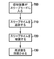
一の態様では、前述のように、感知装置400は、たとえば、電力を節約するために、1つまたは複数の構成要素をスリープさせるか、あるいは非活性状態にする。理解できるように、疑似ランダムチャネルシーケンスを用いて通信しているとき、感知装置400およびゲートウェイ110の周波数は、その2つの間で起こる通信のために一致しなければならない。一の態様では、感知装置400は、所定の期間、スリープしてもよく(図7、ブロック700)、感知装置400がウェイクアップするとき、ゲートウェイ110のホッピング周波数と同期しなければならない。ここで、感知装置400は、たとえば、センサシステムクロック406を使用することによってなどの任意の適切な方法で、感知装置がスリープしている期間(たとえばスリープタイム)を追跡するように構成され(図7、ブロック710)、ウェイクアップする際、たとえば、スリープタイムを補償するためにスリープタイムとほぼ同等の時間待機するように構成され(図7、ブロック720)、それによって、リアルタイムデータが感知装置によって提供され得るように、感知装置400とゲートウェイ110との周波数が通信のためにウェイクアップの際にほぼすぐに同期される(たとえば、感知装置は、スリープからウェイクアップする際に、チャネルホッピングシーケンスのアクティブな周波数を選ぶ)(図7、ブロック730)。一の態様では、周波数の同期を容易にするために、1つまたは複数のゲートウェイ110の周波数ホッピングスキームは、たとえば、感知装置400の記憶装置403内に保存されてもよい。一の態様では、周波数ホッピングスキームおよび/またはセンサシステムクロック406は更新されてもよく、また、クロック406においては、一次および/または二次ゲートウェイと感知装置との間で通信が確立されているときに、任意の適切な時間間隔でゲートウェイのクロック204と同期してもよい。一の態様では、ゲートウェイからの送信の度に、センサシステムクロック406はゲートウェイのクロック204と同期されてもよい(たとえば、ゲートウェイが感知装置に送信信号を送るほぼ全ての度に、ゲートウェイの現在時刻が感知装置に送られる)。
In one aspect, as described above, the
一の態様では、ゲートウェイ110とそれぞれの感知装置400との間のインターフェースは、遠隔的な、感知装置400の任意の適切な所定の特性の設定における変更および/または更新を可能にし得る。一の態様では、所定の特性は、ファームウェアのバージョン、通信インターフェースのための周波数ホッピングシーケンスの1つまたは複数、感知装置の動作日数、感知装置の動作時間、レーダーセンサの強度、磁力計の感度、および磁力計の較正を含んでもよい。理解できるように、各感知装置400の設定の更新は、たとえば、自動的、または中央制御装置のユーザによって手動で開始されるなどの、任意の適切な方法で、中央制御装置101(図1)からもたらされてもよい。センサ400とゲートウェイ110との間の通信インターフェースはまた、正常性および安定性の信号がゲートウェイと感知装置との間で、共有されることを可能にする。一の態様では、感知装置400は、任意の適切な所定の時間間隔で、それぞれのゲートウェイに正常性および安定性のメッセージを送ってもよい。たとえば、一の態様では、正常性および安定性のメッセージは、ほぼ30分ごとに送られてもよいが、他の態様では、正常性および安定性のメッセージは、30分より小さいまたは大きい間隔で送られてもよい。さらに別の態様では、正常性および安定性のメッセージは、感知装置400によってモニタリングされているそれぞれのパーキングスペースの占有状態を含んでもよい。感知装置が交通量の多いエリアにあり、それぞれのパーキングスペース内の占有状態の移行が多いために感知装置がスリープしない場合、感知装置400は、電力を節約するために、それ自体をオフにする(たとえば、スリープする)ように構成されてもよい。ゲートウェイ110は、一次ゲートウェイが感知装置から中央制御装置101(図1)にメッセージを送信することが出来ない場合に感知装置400が二次ゲートウェイに切り替え得るように、それぞれの感知装置400に正常性および安定性のメッセージを送ってもよい。
In one aspect, the interface between the
開示される実施形態の1つまたは複数の態様に従って、分散型遠隔感知システムが提供される。分散型遠隔感知システムは、少なくとも1つのゲートウェイ、少なくとも1つの感知装置、ならびに、共有の周波数スキームによる、各感知装置と少なくとも1つのゲートウェイの1つとの間の、および、異なる周波数スキームによる、各感知装置と少なくとも1つのゲートウェイの別の1つとの間の、無線周波数通信を提供する通信インターフェースを含む。 In accordance with one or more aspects of the disclosed embodiment, a distributed remote sensing system is provided. The distributed remote sensing system includes at least one gateway, at least one sensing device, and each sensing between each sensing device and one of the at least one gateway according to a shared frequency scheme and according to a different frequency scheme. A communication interface that provides radio frequency communication between the device and another one of the at least one gateway.
開示される実施形態の1つまたは複数の態様によると、分散型遠隔感知システムは、パーキングモニタリングシステムを含む。 According to one or more aspects of the disclosed embodiment the distributed remote sensing system includes a parking monitoring system.
開示される実施形態の1つまたは複数の態様によると、通信インターフェースは、少なくとも1つのゲートウェイと周辺装置との間の通信をさらに提供する。 According to one or more aspects of the disclosed embodiment the communication interface further provides communication between the at least one gateway and the peripheral device.
開示される実施形態の1つまたは複数の態様によると、少なくとも1つのゲートウェイと周辺装置との間の通信は、中央制御装置を介している。 According to one or more aspects of the disclosed embodiment, communication between the at least one gateway and the peripheral device is via a central controller.
開示される実施形態の1つまたは複数の態様によると、周辺装置は携帯装置であり、中央制御装置は、周辺装置のディスプレイにパーキングスペースの情報を提供する。 According to one or more aspects of the disclosed embodiment the peripheral device is a portable device and the central controller provides parking space information on the peripheral device display.
開示される実施形態の1つまたは複数の態様によると、分散型遠隔感知システムは、少なくとも1つの感知装置からのデータを処理するように構成された制御装置を含む。 According to one or more aspects of the disclosed embodiment a distributed remote sensing system includes a controller configured to process data from at least one sensing device.
開示される実施形態の1つまたは複数の態様によると、少なくとも1つの感知装置は、少なくとも1つのゲートウェイの1つとの通信の性質に応じて、少なくとも1つのゲートウェイの1つから少なくとも1つのゲートウェイの別の1つに通信を切り替えるように構成される。 In accordance with one or more aspects of the disclosed embodiment, the at least one sensing device is configured to communicate with at least one gateway from one of the at least one gateway, depending on the nature of communication with one of the at least one gateway. It is configured to switch communication to another one.
開示される実施形態の1つまたは複数の態様によると、少なくとも1つの感知装置は、少なくとも1つのゲートウェイの1つから少なくとも1つのゲートウェイの別の1つへの、通信の切り替えを始めるように構成される。 In accordance with one or more aspects of the disclosed embodiment the at least one sensing device is configured to initiate a switch of communication from one of the at least one gateway to another one of the at least one gateway. Is done.
開示される実施形態の1つまたは複数の態様によると、少なくとも1つのゲートウェイの別の1つは、少なくとも1つの感知装置と共有される周波数ホッピングスキームを有する。 According to one or more aspects of the disclosed embodiment, another one of the at least one gateway has a frequency hopping scheme shared with the at least one sensing device.
開示される実施形態の1つまたは複数の態様によると、少なくとも1つの感知装置は、少なくとも1つのゲートウェイの1つから少なくとも1つのゲートウェイの別の1つへの切り替えの時間に対応する、周波数ホッピングスキームの周波数を選択する。 According to one or more aspects of the disclosed embodiment, the at least one sensing device is frequency hopping corresponding to a time of switching from one of the at least one gateway to another one of the at least one gateway. Select the frequency of the scheme.
開示される実施形態の1つまたは複数の態様に従って、分散型遠隔感知システムが提供される。分散型遠隔感知システムは、少なくとも1つのゲートウェイ、少なくとも1つの感知装置、ならびに、共有の周波数スキームによる、各感知装置と少なくとも1つのゲートウェイの1つとの間の、および、異なる周波数スキームによる、各感知装置と少なくとも1つのゲートウェイの別の1つとの間の無線周波数通信を提供する通信インターフェースを含み、通信インターフェースは、少なくとも1つの感知装置と少なくとも1つのゲートウェイとの間の通信の性質に応じた適応型の変化のために構成される。 In accordance with one or more aspects of the disclosed embodiment, a distributed remote sensing system is provided. The distributed remote sensing system includes at least one gateway, at least one sensing device, and each sensing between each sensing device and one of the at least one gateway according to a shared frequency scheme and according to a different frequency scheme. A communication interface for providing radio frequency communication between the device and another one of the at least one gateway, the communication interface being adapted according to the nature of the communication between the at least one sensing device and the at least one gateway Configured for mold changes.
開示される実施形態の1つまたは複数の態様によると、分散型遠隔感知システムは、パーキングモニタリングシステムを含む。 According to one or more aspects of the disclosed embodiment the distributed remote sensing system includes a parking monitoring system.
開示される実施形態の1つまたは複数の態様によると、分散型遠隔感知システムは、少なくとも1つの感知装置からのデータを処理するように構成された制御装置を含む。 According to one or more aspects of the disclosed embodiment a distributed remote sensing system includes a controller configured to process data from at least one sensing device.
開示される実施形態の1つまたは複数の態様によると、少なくとも1つの感知装置は、少なくとも1つのゲートウェイの1つとの通信の性質に応じて、少なくとも1つのゲートウェイの1つから少なくとも1つのゲートウェイの別の1つに通信を切り替えるように構成される。 In accordance with one or more aspects of the disclosed embodiment, the at least one sensing device is configured to communicate with at least one gateway from one of the at least one gateway, depending on the nature of communication with one of the at least one gateway. It is configured to switch communication to another one.
開示される実施形態の1つまたは複数の態様によると、少なくとも1つの感知装置は、少なくとも1つのゲートウェイの1つから少なくとも1つのゲートウェイの別の1つへの、通信の切り替えを始めるように構成される。 In accordance with one or more aspects of the disclosed embodiment the at least one sensing device is configured to initiate a switch of communication from one of the at least one gateway to another one of the at least one gateway. Is done.
開示される実施形態の1つまたは複数の態様に従って、分散型遠隔感知システムが提供される。分散型遠隔感知システムは、少なくとも1つのゲートウェイ、少なくとも1つの感知装置、ならびに、共有の周波数スキームによる、各感知装置と少なくとも1つのゲートウェイの1つとの間の、および、異なる周波数スキームによる、各感知装置と少なくとも1つのゲートウェイの別の1つとの間の無線周波数通信を提供する通信インターフェースを含み、通信インターフェースは、通信インターフェースを通じて、各感知装置の所定の特性の設定を可能にするように構成される。 In accordance with one or more aspects of the disclosed embodiment, a distributed remote sensing system is provided. The distributed remote sensing system includes at least one gateway, at least one sensing device, and each sensing between each sensing device and one of the at least one gateway according to a shared frequency scheme and according to a different frequency scheme. Including a communication interface that provides radio frequency communication between the device and another one of the at least one gateway, the communication interface configured to allow setting of predetermined characteristics of each sensing device through the communication interface. The
開示される実施形態の1つまたは複数の態様によると、分散型遠隔感知システムは、パーキングモニタリングシステムを含む。 According to one or more aspects of the disclosed embodiment the distributed remote sensing system includes a parking monitoring system.
開示される実施形態の1つまたは複数の態様によると、分散型遠隔感知システムは、少なくとも1つの感知装置からのデータを処理するように構成された制御装置を含む。 According to one or more aspects of the disclosed embodiment a distributed remote sensing system includes a controller configured to process data from at least one sensing device.
開示される実施形態の1つまたは複数の態様によると、各感知装置の所定の特性は、通信インターフェースのための周波数ホッピングシーケンスの1つまたは複数、ファームウェアのバージョン、感知装置の動作の日数、感知装置の動作の時間、レーダーセンサの強度、磁力計の感度、および、磁力計の較正、を含む。 In accordance with one or more aspects of the disclosed embodiment, the predetermined characteristics of each sensing device include one or more of the frequency hopping sequences for the communication interface, firmware version, number of days of sensing device operation, sensing Including time of device operation, radar sensor strength, magnetometer sensitivity, and magnetometer calibration.
前記の記載は、開示される実施形態の態様の例証にすぎないことが理解されるべきである。様々な代替例および修正例が、開示される実施形態の態様から逸脱することなく、当業者によって案出され得る。従って、開示された実施形態の態様は、添付された請求項の範囲に該当する、そのような全ての代替例、修正例、および変形例を包含することを意図している。さらに、異なる特徴が相互に異なる従属請求項または独立請求項に列挙されるという単なる事実は、これらの特徴の組み合わせは有利に使用されることが出来ないということは意味せず、そのような組み合わせは本発明の態様の範囲内に留まる。 It should be understood that the foregoing description is only illustrative of the aspects of the disclosed embodiment. Various alternatives and modifications can be devised by those skilled in the art without departing from the aspects of the disclosed embodiments. Accordingly, the aspects of the disclosed embodiments are intended to embrace all such alternatives, modifications and variations that fall within the scope of the appended claims. Furthermore, the mere fact that different features are recited in mutually different dependent or independent claims does not imply that a combination of these features cannot be used to advantage. Remain within the scope of embodiments of the present invention.
Claims (19)
少なくとも1つの感知装置と、
各感知装置と前記少なくとも1つのゲートウェイの1つとの間の共有の周波数スキームによる無線周波数通信、および、各感知装置と前記少なくとも1つのゲートウェイの別の1つとの間の異なる周波数スキームによる無線周波数通信を提供する通信インターフェースと、
を備える、分散型遠隔感知システム。 At least one gateway;
At least one sensing device;
Radio frequency communication with a shared frequency scheme between each sensing device and one of the at least one gateway, and radio frequency communication with a different frequency scheme between each sensing device and another one of the at least one gateway Providing a communication interface;
A distributed remote sensing system comprising:
少なくとも1つのゲートウェイと、
少なくとも1つの感知装置と、
各感知装置と前記少なくとも1つのゲートウェイの1つとの間の共有の周波数スキームによる無線周波数通信、および、各感知装置と前記少なくとも1つのゲートウェイの別の1つとの間の異なる周波数スキームによる無線周波数通信を提供する通信インターフェースとを備え、
前記通信インターフェースが、前記少なくとも1つの感知装置と、前記少なくとも1つのゲートウェイとの間の通信の性質に応じた適応型の変化のために構成される、分散型遠隔感知システム。 A distributed remote sensing system,
At least one gateway;
At least one sensing device;
Radio frequency communication with a shared frequency scheme between each sensing device and one of the at least one gateway, and radio frequency communication with a different frequency scheme between each sensing device and another one of the at least one gateway Providing a communication interface,
A distributed remote sensing system, wherein the communication interface is configured for adaptive change depending on the nature of communication between the at least one sensing device and the at least one gateway.
少なくとも1つのゲートウェイと、
少なくとも1つの感知装置と、
各感知装置と前記少なくとも1つのゲートウェイの1つとの間の共有の周波数スキームによる無線周波数通信、および、各感知装置と前記少なくとも1つのゲートウェイの別の1つとの間の異なる周波数スキームによる無線周波数通信を提供する通信インターフェースとを備え、
前記通信インターフェースが、前記通信インターフェースを通じて、各感知装置の所定の特性の設定を可能にするように構成される、分散型遠隔感知システム。 A distributed remote sensing system,
At least one gateway;
At least one sensing device;
Radio frequency communication with a shared frequency scheme between each sensing device and one of the at least one gateway, and radio frequency communication with a different frequency scheme between each sensing device and another one of the at least one gateway Providing a communication interface,
A distributed remote sensing system, wherein the communication interface is configured to allow setting of predetermined characteristics of each sensing device through the communication interface.
Applications Claiming Priority (5)
| Application Number | Priority Date | Filing Date | Title |
|---|---|---|---|
| US201361824609P | 2013-05-17 | 2013-05-17 | |
| US61/824,609 | 2013-05-17 | ||
| PCT/US2014/038588 WO2014186788A1 (en) | 2013-05-17 | 2014-05-19 | Distributed remote sensing system component interface |
| US14/281,024 US9652987B2 (en) | 2013-05-17 | 2014-05-19 | Distributed remote sensing system component interface |
| US14/281,024 | 2014-05-19 |
Related Child Applications (1)
| Application Number | Title | Priority Date | Filing Date |
|---|---|---|---|
| JP2019166629A Division JP2020017977A (en) | 2013-05-17 | 2019-09-12 | Distributed remote sensing system component interface |
Publications (2)
| Publication Number | Publication Date |
|---|---|
| JP2016531455A true JP2016531455A (en) | 2016-10-06 |
| JP6629188B2 JP6629188B2 (en) | 2020-01-15 |
Family
ID=51895361
Family Applications (2)
| Application Number | Title | Priority Date | Filing Date |
|---|---|---|---|
| JP2016514156A Expired - Fee Related JP6629188B2 (en) | 2013-05-17 | 2014-05-19 | Distributed remote sensing system component interface |
| JP2019166629A Pending JP2020017977A (en) | 2013-05-17 | 2019-09-12 | Distributed remote sensing system component interface |
Family Applications After (1)
| Application Number | Title | Priority Date | Filing Date |
|---|---|---|---|
| JP2019166629A Pending JP2020017977A (en) | 2013-05-17 | 2019-09-12 | Distributed remote sensing system component interface |
Country Status (10)
| Country | Link |
|---|---|
| US (4) | US9652987B2 (en) |
| EP (1) | EP2997723A4 (en) |
| JP (2) | JP6629188B2 (en) |
| CN (2) | CN111508083A (en) |
| AU (3) | AU2014265192B2 (en) |
| BR (1) | BR112015028722A2 (en) |
| CA (1) | CA2912610A1 (en) |
| MX (1) | MX353291B (en) |
| SG (2) | SG11201509385TA (en) |
| WO (1) | WO2014186788A1 (en) |
Families Citing this family (18)
| Publication number | Priority date | Publication date | Assignee | Title |
|---|---|---|---|---|
| US20140343891A1 (en) | 2013-05-17 | 2014-11-20 | fybr | Distributed remote sensing system sensing device |
| US10399495B1 (en) * | 2014-09-05 | 2019-09-03 | United Services Automobile Association (Usaa) | Systems and methods for indicating proximity conditions for a vehicle |
| DE102015216900A1 (en) | 2015-09-03 | 2017-03-09 | Robert Bosch Gmbh | Motor vehicle and parking space for motor vehicles and communication system |
| DE102016206871A1 (en) * | 2016-04-22 | 2017-10-26 | Robert Bosch Gmbh | Sensor device and method for monitoring an occupancy state of a parking space of a parking lot and parking |
| BR112019003566A2 (en) | 2016-08-22 | 2019-05-21 | fybr | system for distributed intelligent remote sensing systems |
| US10692374B2 (en) * | 2017-08-25 | 2020-06-23 | Denise Lisa Salvucci | Automotive vehicle parking systems, methods, and apparatus |
| EP3591853B1 (en) * | 2018-07-02 | 2021-09-01 | Semtech Corporation | Low-power, frequency-hopping, wide-area network with random medium access |
| EP3591852B1 (en) * | 2018-07-02 | 2022-01-12 | Semtech Corporation | Collision mitigation in low-power, frequency-hopping, wide-area network |
| US10847028B2 (en) * | 2018-08-01 | 2020-11-24 | Parkifi, Inc. | Parking sensor magnetometer calibration |
| CN109243183B (en) * | 2018-09-18 | 2020-12-08 | 青岛海信网络科技股份有限公司 | Parking space occupation judgment method and device |
| US10991249B2 (en) | 2018-11-30 | 2021-04-27 | Parkifi, Inc. | Radar-augmentation of parking space sensors |
| CN109981204B (en) * | 2019-02-21 | 2021-03-05 | 福建星云电子股份有限公司 | Multi-machine synchronization method of BMS (battery management system) simulation system |
| CN110535736A (en) * | 2019-08-22 | 2019-12-03 | 厦门盈趣科技股份有限公司 | A kind of method, network node and the home network of dynamic adjustment gateway |
| CN111105509B (en) * | 2019-12-26 | 2022-03-08 | 成都纳雷科技有限公司 | ETC vehicle detection method and system based on millimeter wave radar and storage medium |
| CN111275998A (en) * | 2020-02-03 | 2020-06-12 | 谢华秋 | Parking method and system |
| US11869352B2 (en) * | 2020-02-12 | 2024-01-09 | James CHODORSKI | Emergency alert transmission system and method |
| CN111354218A (en) * | 2020-03-06 | 2020-06-30 | 遂宁市锐毅科技有限公司 | Parking space management method and system |
| CN111674380B (en) * | 2020-06-15 | 2021-09-24 | 中国第一汽车股份有限公司 | Remote vehicle moving system, method, vehicle and storage medium |
Citations (2)
| Publication number | Priority date | Publication date | Assignee | Title |
|---|---|---|---|---|
| JP2004528629A (en) * | 2001-02-07 | 2004-09-16 | ビークルセンス, インク. | Parking management system |
| JP2007535203A (en) * | 2003-07-17 | 2007-11-29 | センシキャスト・システムズ・インコーポレーテッド | Wireless communication method and apparatus in mesh network |
Family Cites Families (68)
| Publication number | Priority date | Publication date | Assignee | Title |
|---|---|---|---|---|
| US4321589A (en) | 1980-07-07 | 1982-03-23 | King Frederick N | Detection system for emergency vehicles with signal preemption means |
| US4626850A (en) | 1983-05-16 | 1986-12-02 | David Chey | Vehicle detection and collision avoidance apparatus |
| US5182564A (en) | 1984-07-26 | 1993-01-26 | The Boeing Company | Guidance apparatus with dual mode sensor |
| JP3022156B2 (en) | 1994-05-10 | 2000-03-15 | 松下電工株式会社 | Parking lot control system equipment |
| US5640386A (en) | 1995-06-06 | 1997-06-17 | Globalstar L.P. | Two-system protocol conversion transceiver repeater |
| US5672975A (en) * | 1995-06-07 | 1997-09-30 | Rosemount Inc. | Two-wire level transmitter |
| WO1999061933A2 (en) | 1998-04-16 | 1999-12-02 | Raytheon Company | Airborne gps guidance system for defeating multiple jammers |
| US6437692B1 (en) * | 1998-06-22 | 2002-08-20 | Statsignal Systems, Inc. | System and method for monitoring and controlling remote devices |
| AU6031499A (en) | 1998-09-11 | 2000-04-03 | Key-Trak, Inc. | Object control and tracking system with zonal transition detection |
| JP2003508939A (en) * | 1999-05-28 | 2003-03-04 | ベーシック・リソーシィズ・インコーポレイテッド | Wireless transceiver network using inter-node data messages |
| JP3096291B1 (en) | 1999-06-08 | 2000-10-10 | 勝 伊東 | Abrasion-resistant composite metal material and method for producing the same |
| US8140658B1 (en) | 1999-10-06 | 2012-03-20 | Borgia/Cummins, Llc | Apparatus for internetworked wireless integrated network sensors (WINS) |
| JP4522521B2 (en) | 2000-01-19 | 2010-08-11 | 日本信号株式会社 | Parking meter centralized monitoring system |
| US6502053B1 (en) | 2000-06-12 | 2002-12-31 | Larry Hardin | Combination passive and active speed detection system |
| US20080074259A1 (en) | 2000-09-21 | 2008-03-27 | Robert Houston | Solar powered security system |
| CA2363915A1 (en) | 2001-11-27 | 2003-05-27 | J.J. Mackay Canada Limited | Parking meter reset device |
| US6825778B2 (en) | 2002-10-21 | 2004-11-30 | International Road Dynamics Inc. | Variable speed limit system |
| JP3096291U (en) | 2003-01-31 | 2003-09-12 | 株式会社スリーエス | Management meter with solar panel |
| US7019639B2 (en) * | 2003-02-03 | 2006-03-28 | Ingrid, Inc. | RFID based security network |
| US7113127B1 (en) * | 2003-07-24 | 2006-09-26 | Reynolds And Reynolds Holdings, Inc. | Wireless vehicle-monitoring system operating on both terrestrial and satellite networks |
| JP2005085187A (en) | 2003-09-11 | 2005-03-31 | Oki Electric Ind Co Ltd | Parking lot management system utilizing radio lan system |
| US7104447B1 (en) | 2003-12-15 | 2006-09-12 | Anthony Lopez | Parking meters, systems and methods of parking enforcement |
| US8031650B2 (en) | 2004-03-03 | 2011-10-04 | Sipco, Llc | System and method for monitoring remote devices with a dual-mode wireless communication protocol |
| EP1730506B1 (en) * | 2004-04-02 | 2018-09-26 | Silicon Laboratories Inc. | An integrated electronic sensor |
| US8145219B2 (en) * | 2004-07-28 | 2012-03-27 | Broadcom Corporation | Handoff of a multimedia call session using background network scanning |
| KR100871200B1 (en) * | 2004-11-05 | 2008-12-01 | 메시네트웍스, 인코포레이티드 | Method and node for dynamic frequency selection in a multihopping wireless network |
| US20060197650A1 (en) | 2005-03-02 | 2006-09-07 | Magnadyne Corporation | Passive transmitter |
| WO2007027945A1 (en) | 2005-08-30 | 2007-03-08 | Sensact Applications, Incorporated | Wireless parking guidance system |
| US20070085067A1 (en) | 2005-10-18 | 2007-04-19 | Lewis John R | Gated parking corral |
| US20070093974A1 (en) * | 2005-10-20 | 2007-04-26 | Hoogenboom Christopher L | Remote configuration of a sensor for monitoring the structural integrity of a building |
| US20110298603A1 (en) | 2006-03-06 | 2011-12-08 | King Timothy I | Intersection Collision Warning System |
| JP5046560B2 (en) | 2006-05-29 | 2012-10-10 | 株式会社アイテック | Parking lot management system and management method thereof |
| US7868784B2 (en) * | 2006-12-22 | 2011-01-11 | Industrial Technology Research Institute | System and apparatus for parking management |
| CN100576278C (en) * | 2007-04-23 | 2009-12-30 | 财团法人工业技术研究院 | Wireless sensor and the intelligent traffic control system and the method that drive the networking |
| JP2009260778A (en) | 2008-04-18 | 2009-11-05 | Hitachi High-Tech Control Systems Corp | Sensor network gateway, and sensor network system |
| US8787266B2 (en) | 2008-06-13 | 2014-07-22 | Infineon Technologies Ag | Medium access control in industrial and automotive wireless with combined wired and wireless sensor networks |
| NL1036075C (en) | 2008-10-15 | 2010-04-16 | Univ Eindhoven Tech | DETECTION UNIT FOR OBSERVATION OF AN EVENT, DETECTION SYSTEM, AND METHODS FOR CONTROLLING SUCH A DETECTION UNIT OR DETECTION SYSTEM. |
| WO2010069002A1 (en) | 2008-12-19 | 2010-06-24 | Park Assist Pty Ltd | Method, apparatus and system for vehicle detection |
| WO2010071972A1 (en) * | 2008-12-23 | 2010-07-01 | J.J.Mackay Canada Limited | Low power wireless parking meter and parking meter network |
| CH700149A1 (en) | 2008-12-23 | 2010-06-30 | Dzotec Sa | The standalone radar electrically. |
| WO2010081547A1 (en) * | 2009-01-14 | 2010-07-22 | Tomtom International B.V. | Navigation apparatus, server apparatus and method of collecting parking location information |
| CA2725784A1 (en) * | 2009-01-14 | 2010-07-22 | Tomtom International B.V. | Navigation apparatus and method |
| JP5348013B2 (en) * | 2009-05-26 | 2013-11-20 | ソニー株式会社 | Wireless communication apparatus, estimation server, wireless communication method, and estimation method |
| US20110218940A1 (en) | 2009-07-28 | 2011-09-08 | Recharge Power Llc | Parking Meter System |
| US8330624B2 (en) * | 2009-08-10 | 2012-12-11 | Eric Groft | Enhancements to meterless remote parking monitoring systems |
| US20110082991A1 (en) | 2009-10-02 | 2011-04-07 | Softthinks Sas | Remote backup with local buffering |
| US8981959B2 (en) * | 2010-06-02 | 2015-03-17 | Badger Meter, Inc. | Apparatus and method for priority addressing and message handling in a fixed meter reading network |
| WO2012037637A1 (en) * | 2010-09-23 | 2012-03-29 | Research In Motion Limited | System and method for dynamic coordination of radio resources usage in a wireless network environment |
| US8964568B2 (en) * | 2010-10-22 | 2015-02-24 | Qualcomm Incorporated | Systems, methods, and apparatus for managing IP addresses and network traffic in wireless networks |
| US20120185569A1 (en) * | 2011-01-14 | 2012-07-19 | Qualcomm Incorporated | Techniques for dynamic task processing in a wireless communication system |
| US20120182160A1 (en) | 2011-01-14 | 2012-07-19 | TCS International, Inc. | Directional Vehicle Sensor Matrix |
| US8662279B2 (en) * | 2011-05-10 | 2014-03-04 | Duncan Solutions, Inc. | Upgraded single space parking meter and method |
| JP5687567B2 (en) * | 2011-06-01 | 2015-03-18 | 富士通株式会社 | Node device, communication system, and channel selection method |
| EP2530850A3 (en) * | 2011-06-03 | 2015-07-08 | Samsung Electronics Co., Ltd. | Repeater connected to a gateway and a client device via the Wi-Fi protocol with filtering of different frequency bands. |
| JP2012257016A (en) | 2011-06-08 | 2012-12-27 | Panasonic Corp | Radio system |
| US9072100B2 (en) * | 2011-07-20 | 2015-06-30 | Cisco Technology, Inc. | Sub-slotting to improve packet success rate in carrier sense multiple access networks |
| US8704676B2 (en) | 2011-08-09 | 2014-04-22 | Qualcomm Incorporated | Dynamic road markers to provide visual feedback as to vehicle speed |
| US20130201316A1 (en) * | 2012-01-09 | 2013-08-08 | May Patents Ltd. | System and method for server based control |
| US9781745B2 (en) * | 2012-03-19 | 2017-10-03 | Tyco Fire & Security Gmbh | Scalable protocol for large WSNS having low duty cycle end nodes |
| CN102769894A (en) * | 2012-07-04 | 2012-11-07 | 上海大学 | Multi-gateway multi-node wireless sensor network and multi-gateway channel selection and node adaptive network access method for same |
| CN102882751B (en) | 2012-09-21 | 2016-01-27 | 鸿富锦精密工业(深圳)有限公司 | Intelligent domestic network system and chromacoder thereof |
| CN103002597A (en) * | 2012-11-29 | 2013-03-27 | 大连工业大学 | Seamless connection multi-gateway wireless sensor network (WSN) structure |
| US20140210646A1 (en) | 2012-12-28 | 2014-07-31 | Balu Subramanya | Advanced parking and intersection management system |
| ES2873203T3 (en) | 2013-01-25 | 2021-11-03 | Municipal Parking Services Inc | Parking meter system |
| US10121172B2 (en) | 2013-01-25 | 2018-11-06 | Municipal Parking Services Inc. | Parking lot monitoring system |
| US20140324614A1 (en) | 2013-04-25 | 2014-10-30 | Readme Systems, Inc. | Systems, methods, and devices for providing a retail store platform for interacting with shoppers in real-time |
| SG11201509422SA (en) * | 2013-05-17 | 2015-12-30 | fybr | Distributed remote sensing system gateway |
| CN110177415B (en) * | 2013-10-23 | 2022-02-01 | 鲍尔卡斯特公司 | Automated system for lighting control |
-
2014
- 2014-05-19 AU AU2014265192A patent/AU2014265192B2/en not_active Ceased
- 2014-05-19 WO PCT/US2014/038588 patent/WO2014186788A1/en active Application Filing
- 2014-05-19 SG SG11201509385TA patent/SG11201509385TA/en unknown
- 2014-05-19 CN CN202010127826.XA patent/CN111508083A/en active Pending
- 2014-05-19 SG SG10201803681QA patent/SG10201803681QA/en unknown
- 2014-05-19 EP EP14797134.5A patent/EP2997723A4/en not_active Withdrawn
- 2014-05-19 CN CN201480040331.6A patent/CN105594189B/en not_active Expired - Fee Related
- 2014-05-19 CA CA2912610A patent/CA2912610A1/en active Pending
- 2014-05-19 BR BR112015028722A patent/BR112015028722A2/en not_active Application Discontinuation
- 2014-05-19 MX MX2015015763A patent/MX353291B/en active IP Right Grant
- 2014-05-19 JP JP2016514156A patent/JP6629188B2/en not_active Expired - Fee Related
- 2014-05-19 US US14/281,024 patent/US9652987B2/en active Active
-
2017
- 2017-05-12 US US15/593,799 patent/US9852630B2/en active Active
- 2017-12-15 US US15/844,230 patent/US10937317B2/en active Active
-
2018
- 2018-06-06 AU AU2018204005A patent/AU2018204005B2/en not_active Ceased
-
2019
- 2019-09-12 JP JP2019166629A patent/JP2020017977A/en active Pending
-
2020
- 2020-05-22 AU AU2020203357A patent/AU2020203357B2/en not_active Expired - Fee Related
-
2021
- 2021-03-02 US US17/189,956 patent/US20210183248A1/en not_active Abandoned
Patent Citations (2)
| Publication number | Priority date | Publication date | Assignee | Title |
|---|---|---|---|---|
| JP2004528629A (en) * | 2001-02-07 | 2004-09-16 | ビークルセンス, インク. | Parking management system |
| JP2007535203A (en) * | 2003-07-17 | 2007-11-29 | センシキャスト・システムズ・インコーポレーテッド | Wireless communication method and apparatus in mesh network |
Also Published As
| Publication number | Publication date |
|---|---|
| WO2014186788A1 (en) | 2014-11-20 |
| CA2912610A1 (en) | 2014-11-20 |
| AU2014265192B2 (en) | 2018-05-17 |
| US9652987B2 (en) | 2017-05-16 |
| AU2018204005A1 (en) | 2018-06-21 |
| CN105594189A (en) | 2016-05-18 |
| US10937317B2 (en) | 2021-03-02 |
| US20170249841A1 (en) | 2017-08-31 |
| EP2997723A4 (en) | 2017-03-29 |
| US9852630B2 (en) | 2017-12-26 |
| US20180130352A1 (en) | 2018-05-10 |
| BR112015028722A2 (en) | 2017-07-25 |
| US20210183248A1 (en) | 2021-06-17 |
| US20140340240A1 (en) | 2014-11-20 |
| JP6629188B2 (en) | 2020-01-15 |
| AU2018204005B2 (en) | 2020-05-21 |
| AU2020203357B2 (en) | 2022-05-26 |
| AU2014265192A1 (en) | 2015-12-03 |
| CN105594189B (en) | 2020-03-27 |
| AU2020203357A1 (en) | 2020-06-11 |
| JP2020017977A (en) | 2020-01-30 |
| CN111508083A (en) | 2020-08-07 |
| SG11201509385TA (en) | 2015-12-30 |
| EP2997723A1 (en) | 2016-03-23 |
| MX353291B (en) | 2018-01-05 |
| SG10201803681QA (en) | 2018-06-28 |
| MX2015015763A (en) | 2016-08-03 |
Similar Documents
| Publication | Publication Date | Title |
|---|---|---|
| AU2020203357B2 (en) | Distributed remote sensing system component interface | |
| JP2019125380A (en) | Distributed remote sensing system gateway | |
| US11699346B1 (en) | Advanced parking management system | |
| US20220030335A1 (en) | Retrofit vehicle sensor | |
| US7714742B1 (en) | Wireless mesh network parking measurement system | |
| US20180322710A1 (en) | Method for detecting parked vehicles and for collecting parking fees | |
| US20140343891A1 (en) | Distributed remote sensing system sensing device | |
| DK2709071T3 (en) | PROCEDURE, WIRELESS RADIO FIRE AND ONBOARD DEVICE FOR GENERATION OF PARKING FEE TRANSACTIONS | |
| CN108777077A (en) | A kind of road-surface concrete management system, server and method | |
| WO2012002838A2 (en) | Method for transmitting data relating to the location and status of vehicles in transport monitoring systems | |
| WO2022238994A1 (en) | Multi-space parking detection units and method of use |
Legal Events
| Date | Code | Title | Description |
|---|---|---|---|
| A529 | Written submission of copy of amendment under article 34 pct |
Free format text: JAPANESE INTERMEDIATE CODE: A529 Effective date: 20160115 |
|
| RD01 | Notification of change of attorney |
Free format text: JAPANESE INTERMEDIATE CODE: A7426 Effective date: 20160115 |
|
| A621 | Written request for application examination |
Free format text: JAPANESE INTERMEDIATE CODE: A621 Effective date: 20170508 |
|
| A977 | Report on retrieval |
Free format text: JAPANESE INTERMEDIATE CODE: A971007 Effective date: 20180530 |
|
| A131 | Notification of reasons for refusal |
Free format text: JAPANESE INTERMEDIATE CODE: A131 Effective date: 20180605 |
|
| A601 | Written request for extension of time |
Free format text: JAPANESE INTERMEDIATE CODE: A601 Effective date: 20180827 |
|
| A521 | Request for written amendment filed |
Free format text: JAPANESE INTERMEDIATE CODE: A523 Effective date: 20181204 |
|
| A131 | Notification of reasons for refusal |
Free format text: JAPANESE INTERMEDIATE CODE: A131 Effective date: 20190312 |
|
| A601 | Written request for extension of time |
Free format text: JAPANESE INTERMEDIATE CODE: A601 Effective date: 20190610 |
|
| A521 | Request for written amendment filed |
Free format text: JAPANESE INTERMEDIATE CODE: A523 Effective date: 20190912 |
|
| TRDD | Decision of grant or rejection written | ||
| A01 | Written decision to grant a patent or to grant a registration (utility model) |
Free format text: JAPANESE INTERMEDIATE CODE: A01 Effective date: 20191105 |
|
| A61 | First payment of annual fees (during grant procedure) |
Free format text: JAPANESE INTERMEDIATE CODE: A61 Effective date: 20191204 |
|
| R150 | Certificate of patent or registration of utility model |
Ref document number: 6629188 Country of ref document: JP Free format text: JAPANESE INTERMEDIATE CODE: R150 |
|
| LAPS | Cancellation because of no payment of annual fees |