JP2016526427A - Dispenser for dispensing unit dose of active pharmaceutical substance in solid dosage form - Google Patents
Dispenser for dispensing unit dose of active pharmaceutical substance in solid dosage form Download PDFInfo
- Publication number
- JP2016526427A JP2016526427A JP2016522719A JP2016522719A JP2016526427A JP 2016526427 A JP2016526427 A JP 2016526427A JP 2016522719 A JP2016522719 A JP 2016522719A JP 2016522719 A JP2016522719 A JP 2016522719A JP 2016526427 A JP2016526427 A JP 2016526427A
- Authority
- JP
- Japan
- Prior art keywords
- chamber
- unit dose
- processing unit
- unit
- dispensing
- Prior art date
- Legal status (The legal status is an assumption and is not a legal conclusion. Google has not performed a legal analysis and makes no representation as to the accuracy of the status listed.)
- Pending
Links
Images


Classifications
-
- B—PERFORMING OPERATIONS; TRANSPORTING
- B65—CONVEYING; PACKING; STORING; HANDLING THIN OR FILAMENTARY MATERIAL
- B65D—CONTAINERS FOR STORAGE OR TRANSPORT OF ARTICLES OR MATERIALS, e.g. BAGS, BARRELS, BOTTLES, BOXES, CANS, CARTONS, CRATES, DRUMS, JARS, TANKS, HOPPERS, FORWARDING CONTAINERS; ACCESSORIES, CLOSURES, OR FITTINGS THEREFOR; PACKAGING ELEMENTS; PACKAGES
- B65D83/00—Containers or packages with special means for dispensing contents
- B65D83/04—Containers or packages with special means for dispensing contents for dispensing annular, disc-shaped, or spherical or like small articles, e.g. tablets or pills
- B65D83/0409—Containers or packages with special means for dispensing contents for dispensing annular, disc-shaped, or spherical or like small articles, e.g. tablets or pills the dispensing means being adapted for delivering one article, or a single dose, upon each actuation
-
- B—PERFORMING OPERATIONS; TRANSPORTING
- B65—CONVEYING; PACKING; STORING; HANDLING THIN OR FILAMENTARY MATERIAL
- B65D—CONTAINERS FOR STORAGE OR TRANSPORT OF ARTICLES OR MATERIALS, e.g. BAGS, BARRELS, BOTTLES, BOXES, CANS, CARTONS, CRATES, DRUMS, JARS, TANKS, HOPPERS, FORWARDING CONTAINERS; ACCESSORIES, CLOSURES, OR FITTINGS THEREFOR; PACKAGING ELEMENTS; PACKAGES
- B65D25/00—Details of other kinds or types of rigid or semi-rigid containers
- B65D25/02—Internal fittings
- B65D25/10—Devices to locate articles in containers
- B65D25/101—Springs, elastic lips, or other resilient elements to locate the articles by pressure
-
- B—PERFORMING OPERATIONS; TRANSPORTING
- B65—CONVEYING; PACKING; STORING; HANDLING THIN OR FILAMENTARY MATERIAL
- B65D—CONTAINERS FOR STORAGE OR TRANSPORT OF ARTICLES OR MATERIALS, e.g. BAGS, BARRELS, BOTTLES, BOXES, CANS, CARTONS, CRATES, DRUMS, JARS, TANKS, HOPPERS, FORWARDING CONTAINERS; ACCESSORIES, CLOSURES, OR FITTINGS THEREFOR; PACKAGING ELEMENTS; PACKAGES
- B65D49/00—Arrangements or devices for preventing refilling of containers
- B65D49/12—Arrangements or devices for preventing refilling of containers by destroying, in the act of opening the container, an integral portion thereof
-
- B—PERFORMING OPERATIONS; TRANSPORTING
- B65—CONVEYING; PACKING; STORING; HANDLING THIN OR FILAMENTARY MATERIAL
- B65D—CONTAINERS FOR STORAGE OR TRANSPORT OF ARTICLES OR MATERIALS, e.g. BAGS, BARRELS, BOTTLES, BOXES, CANS, CARTONS, CRATES, DRUMS, JARS, TANKS, HOPPERS, FORWARDING CONTAINERS; ACCESSORIES, CLOSURES, OR FITTINGS THEREFOR; PACKAGING ELEMENTS; PACKAGES
- B65D51/00—Closures not otherwise provided for
- B65D51/24—Closures not otherwise provided for combined or co-operating with auxiliary devices for non-closing purposes
- B65D51/26—Closures not otherwise provided for combined or co-operating with auxiliary devices for non-closing purposes with means for keeping contents in position, e.g. resilient means
-
- B—PERFORMING OPERATIONS; TRANSPORTING
- B65—CONVEYING; PACKING; STORING; HANDLING THIN OR FILAMENTARY MATERIAL
- B65D—CONTAINERS FOR STORAGE OR TRANSPORT OF ARTICLES OR MATERIALS, e.g. BAGS, BARRELS, BOTTLES, BOXES, CANS, CARTONS, CRATES, DRUMS, JARS, TANKS, HOPPERS, FORWARDING CONTAINERS; ACCESSORIES, CLOSURES, OR FITTINGS THEREFOR; PACKAGING ELEMENTS; PACKAGES
- B65D51/00—Closures not otherwise provided for
- B65D51/24—Closures not otherwise provided for combined or co-operating with auxiliary devices for non-closing purposes
- B65D51/28—Closures not otherwise provided for combined or co-operating with auxiliary devices for non-closing purposes with auxiliary containers for additional articles or materials
- B65D51/30—Closures not otherwise provided for combined or co-operating with auxiliary devices for non-closing purposes with auxiliary containers for additional articles or materials for desiccators
-
- B—PERFORMING OPERATIONS; TRANSPORTING
- B65—CONVEYING; PACKING; STORING; HANDLING THIN OR FILAMENTARY MATERIAL
- B65D—CONTAINERS FOR STORAGE OR TRANSPORT OF ARTICLES OR MATERIALS, e.g. BAGS, BARRELS, BOTTLES, BOXES, CANS, CARTONS, CRATES, DRUMS, JARS, TANKS, HOPPERS, FORWARDING CONTAINERS; ACCESSORIES, CLOSURES, OR FITTINGS THEREFOR; PACKAGING ELEMENTS; PACKAGES
- B65D81/00—Containers, packaging elements, or packages, for contents presenting particular transport or storage problems, or adapted to be used for non-packaging purposes after removal of contents
- B65D81/24—Adaptations for preventing deterioration or decay of contents; Applications to the container or packaging material of food preservatives, fungicides, pesticides or animal repellants
- B65D81/26—Adaptations for preventing deterioration or decay of contents; Applications to the container or packaging material of food preservatives, fungicides, pesticides or animal repellants with provision for draining away, or absorbing, or removing by ventilation, fluids, e.g. exuded by contents; Applications of corrosion inhibitors or desiccators
- B65D81/266—Adaptations for preventing deterioration or decay of contents; Applications to the container or packaging material of food preservatives, fungicides, pesticides or animal repellants with provision for draining away, or absorbing, or removing by ventilation, fluids, e.g. exuded by contents; Applications of corrosion inhibitors or desiccators for absorbing gases, e.g. oxygen absorbers or desiccants
-
- B—PERFORMING OPERATIONS; TRANSPORTING
- B65—CONVEYING; PACKING; STORING; HANDLING THIN OR FILAMENTARY MATERIAL
- B65D—CONTAINERS FOR STORAGE OR TRANSPORT OF ARTICLES OR MATERIALS, e.g. BAGS, BARRELS, BOTTLES, BOXES, CANS, CARTONS, CRATES, DRUMS, JARS, TANKS, HOPPERS, FORWARDING CONTAINERS; ACCESSORIES, CLOSURES, OR FITTINGS THEREFOR; PACKAGING ELEMENTS; PACKAGES
- B65D2215/00—Child-proof means
- B65D2215/02—Child-proof means requiring the combination of simultaneous actions
Abstract
本発明は、固体剤形の活性物質のユニットドーズ(Mi)を分与するための安全な装置に関する。こうした装置は、ユニットドーズを収容するチャンバの再充填を防ぐ手段を備える。装置は、処理ユニットと、外の世界と通信するための手段とをさらに受け入れる(51)ことができる。こうした装置は、薬の偽造に対抗するのに特に効果的である。装置はさらに、臨床試験中の患者の不遵守、又は慢性疾患を患っている患者の不遵守を検出するために使用できる。The present invention relates to a safe device for dispensing a unit dose (Mi) of an active substance in solid dosage form. Such an apparatus comprises means for preventing refilling of the chamber containing the unit dose. The apparatus may further accept 51 a processing unit and means for communicating with the outside world. Such devices are particularly effective in combating drug counterfeiting. The device can further be used to detect patient non-compliance during a clinical trial or non-compliance of a patient suffering from a chronic disease.
Description
本発明は、固体剤形の薬剤物質のユニットドーズを分与するための装置に関する。具体的には、本発明は、医薬品の偽造、及び患者の臨床試験プロトコルの不遵守又は慢性的に体調がすぐれない患者の不遵守の対策に関する。 The present invention relates to an apparatus for dispensing a unit dose of a drug substance in a solid dosage form. Specifically, the present invention relates to measures against counterfeiting of pharmaceuticals and non-compliance of patients' clinical trial protocols or chronically unwell patients.
薬の偽造は世界的な現象である。偽造医薬品は世界的な薬剤取引の10%以上を占めることを調査は示している。或る途上国では、2つの薬剤のうちの1つは偽造薬である場合がある。世界保健機関によれば、偽造は、毎年750億ドル以上に相当する闇経済を生み出し、所謂先進国も例外ではないことが浮き彫りになっている。1992年以来、多数の世界保健機関(WHO)加盟諸国、国際刑事警察機構、世界関税機関、国際麻薬統制委員会、国際製薬団体連合会、国際消費者団体、並びに国際薬学連合は、以下の定義を承認した。「偽造医薬品は、「同一性や出所起源に関して、故意に不正に偽造表示された」製品である。偽造は、先発医薬品と後発医薬品との両方に当てはめることができ、偽造製品は、正しい又は誤った成分若しくは賦形剤を有する、活性成分を有さない、不十分な活性成分を有する、又は偽のパッケージを有する製品を含む場合がある。」 Forgery of medicine is a global phenomenon. Research shows that counterfeit drugs account for more than 10% of global drug trade. In certain developing countries, one of the two drugs may be a counterfeit drug. According to the World Health Organization, counterfeiting creates a dark economy worth more than $ 75 billion annually, and so-called developed countries are no exception. Since 1992, many World Health Organization (WHO) member states, the International Criminal Police Organization, the World Customs Organization, the International Drug Control Committee, the International Pharmaceutical Association, the International Consumer Organization, and the International Pharmaceutical Association have the following definitions: Approved. “Counterfeit medicines” are products that are “intentionally fraudulently labeled with respect to identity and origin”. Counterfeiting can be applied to both original and generic drugs, and counterfeit products have the right or wrong ingredients or excipients, no active ingredients, insufficient active ingredients, or fake May include a product having a package of "
薬剤の偽造は、患者の健康と安全性に直接影響する。これはまた、産業部門で営業する会社及び政府機関の財政を危うくする。 Drug counterfeiting has a direct impact on patient health and safety. This also jeopardizes the finances of companies and government agencies operating in the industrial sector.
例として、偽造されている薬の特徴を再現できない偽造薬によって生じる影響は、治療の失敗につながる場合があり、抗生物質などの特定の薬剤物質への耐性をもたらすこともある。偽造医薬品は、患者の健康を脅かす又は様々な合併症を介して病気の悪化を引き起こすことがある。これはまた、患者、特に子供及び高齢者などの弱い人々の死を直接引き起こす可能性がある。 By way of example, the effects caused by counterfeit drugs that cannot reproduce the characteristics of the counterfeit drug may lead to treatment failure and may result in resistance to certain drug substances such as antibiotics. Counterfeit medicines can threaten patient health or cause disease deterioration through various complications. This can also directly cause the death of patients, especially vulnerable people such as children and the elderly.
製薬産業は、増えつつある悪意のある偽造に関連した危険をはっきりと意識している。これはまた、フランスの製薬会社だけで1年に約60億ユーロの多大な資金欠損を計上し、とりわけそのパッケージングチェーン及び流通経路の確保を図ることによって偽造に対抗する新戦略を実施する試みがなされている。 The pharmaceutical industry is clearly aware of the dangers associated with an increasing number of malicious counterfeiting. This is also an attempt to implement a new strategy to counter counterfeiting, especially by securing a packaging chain and distribution channel, with a significant loss of funds of around 6 billion euros per year at the French pharmaceutical company alone. Has been made.
官公庁もこの現象に対処するべく動かされている。政府も、多大な財務上の損失に悩まされている。公衆衛生への脅威は、有害な製品に曝されている場合がある人々の医療費をカバーするために、及び、偽造薬の在庫の差し替えのために実質的な費用を生み出す。現場の医薬品供給経路の制御及び監視サービスの強化によってもリソースの消費が増加の一途をたどっている。 Government agencies are also moving to deal with this phenomenon. The government is also suffering from significant financial losses. The public health threat creates substantial costs to cover the medical costs of people who may be exposed to harmful products and to replace the inventory of counterfeit drugs. Consumption of resources continues to increase as a result of strengthening control and monitoring services for on-site pharmaceutical supply.
今日まで開発された又は関係者によって実施された解決策及び戦略は、費用がかさみ、比較的効率的でないことが証明されている。しかもなお悪いことに、一部の意見では、これらの戦略は、不可欠であると考えられたが、研究にあてられる出資をさらに抑制し、新分子の開発を制限する可能性がある。偽造者は特に巧妙であり、彼らはほぼ同じ見た目の、しかし明らかに活性成分を含有しない、ボトル、バイアル、ブリスターパック、錠剤、及びカプセルをなんとか再現しようとする。一部の偽造者はさらに、空の元の容器をリサイクルし、それらに偽造医薬品を詰め替え、前記容器を市場に再導入する。 Solutions and strategies developed to date or implemented by interested parties have proven costly and relatively inefficient. To make matters worse, in some opinions, these strategies were considered essential, but they could further constrain funding for research and limit the development of new molecules. Counterfeiters are particularly clever and they try to recreate bottles, vials, blister packs, tablets, and capsules that look almost the same, but clearly contain no active ingredients. Some counterfeiters further recycle empty original containers, refill them with counterfeit drugs, and reintroduce the containers to the market.
製薬産業は、患者の臨床試験プロトコルの不遵守に関連した第2の問題に直面している。臨床試験の目的は、特に投薬計画に関する厳しいプロトコルに従うことに同意する患者に対する活性物質の効果を評価することである。彼らはまた、自分が観察した何らかのポジティブな影響又はネガティブな影響についての正確な報告をする又は臨床上のアンケートに記入しなければならない。薬剤の服薬の順守は、それが特定の治療指示で推奨するのに最も効果的な毒性のないドーズ又は適正な用量を確立する唯一の方法であるため、臨床試験段階の臨床相では極めて重要である。したがって、でたらめに薬を服用するなどの患者によるプロトコルの順守又は遵守の失敗は、結果的に不精確な又は不十分なデータの収集をもたらす。偏った臨床試験は、効き目がある可能性のある薬剤の放棄、又は逆に、効き目の疑わしい薬剤又はさらには確立された用量では有毒な薬剤の承認につながることがある。患者の臨床試験プロトコルの不遵守は、残念なことによくある挙動である。新薬開発の平均費用は、ほぼ10億ユーロと推定される。販売許可を得る又は研究を活用するのに要する時間は、約12年(時にはそれ以上)である。臨床試験中の患者の不遵守をなくそうと努めること又は少なくともこれを検出することは、製薬産業にとっての第2の課題である。臨床試験の実施に関連した費用及び時間を減らすには、登録された被検者の臨床プロトコルの遵守を向上させることによってその結果の妥当性及び質を向上させることが不可欠である。したがって、利害関係者らは、情報伝達型のパンフレット、ホットライン、ウェブサイトなどを通じて患者の意識及び心がけの向上に努める。患者がプロトコル及び医師の推奨に従うのを助けるために、一部の利害関係者は、いつ薬剤を服用するか及びいつ医師との予定された面会を行うかをリマインドするシステムを確立することを試みている。リマインダは、電話、電子メール、又は電子手帳を通じて行われる場合がある。他の利害関係者らは、例えば患者にいつ服用させるかをリマインドするタイマを有する新しい形態の「スマート」パックを開発した。こうした解決策は非常に高価であり、患者の臨床プロトコルの不遵守を判定する、したがって検出することを可能にしない。 The pharmaceutical industry faces a second problem associated with non-compliance with patient clinical trial protocols. The purpose of clinical trials is to assess the effect of active substances on patients who agree to follow a strict protocol, especially regarding dosing schedules. They must also make accurate reports or fill out clinical questionnaires about any positive or negative effects they have observed. Adherence to medication is extremely important in the clinical phase of the clinical trial phase, as it is the only way to establish the most effective non-toxic dose or the appropriate dose to recommend with a specific treatment instruction. is there. Thus, failure to comply or adhere to the protocol by the patient, such as taking medications randomly, results in inaccurate or insufficient data collection. Biased clinical trials can lead to the abandonment of potentially efficacious drugs, or conversely, approval of suspicious drugs or even toxic drugs at established doses. Unfortunately, patient compliance with clinical trial protocols is a common behavior. The average cost of new drug development is estimated at almost 1 billion euros. The time required to obtain a marketing license or to utilize research is about 12 years (sometimes more). Attempting to eliminate or at least detect patient non-compliance during clinical trials is a second challenge for the pharmaceutical industry. To reduce the costs and time associated with conducting clinical trials, it is essential to improve the validity and quality of the results by improving the compliance of registered subjects with clinical protocols. Stakeholders therefore strive to improve patient awareness and awareness through information-driven brochures, hotlines, websites, and the like. To help patients follow the protocol and physician recommendations, some stakeholders have attempted to establish a system that reminds them when to take the drug and when to have a scheduled visit to the physician. ing. The reminder may be performed through a telephone, e-mail, or electronic notebook. Other stakeholders have developed a new form of “smart” pack with a timer that reminds the patient when to take it, for example. These solutions are very expensive and do not make it possible to determine and thus detect non-compliance with a patient's clinical protocol.
本発明は、現在の解決策の欠点のほとんどへの打開案を提供する。 The present invention provides a solution to most of the shortcomings of current solutions.
本発明の多くの利点のうち、以下、つまり、
内容物と容器との一貫性を証明する悪意のある偽造医薬品への効果的な対策をとること、
薬剤物質のすべての固体剤形に適応できる経済的な容器又はディスペンサを提供すること、
種々の実施形態によれば、
薬剤ディスペンサを大気中の湿度の高い領域に配備することで、薬の薬剤物質及びそれらの完全な状態を保つこと、
ディスペンサ内の前記ドーズ間の衝突から生じる薬剤ユニットドーズの損傷を防ぐこと、
高齢者による容易な使用を維持しながら、監視されていない子供へのドーズの送達を防ぐことによって、事故又は薬剤中毒のリスクを制限すること、
患者の臨床試験プロトコルの遵守、又は慢性疾患を患っている患者における不遵守を評価すること、及び、
治療処置中の患者支援サービスの実施に寄与すること、
を選び出すことができる。
Among the many advantages of the present invention, the following:
Taking effective measures against malicious counterfeit drugs that demonstrate consistency between contents and containers;
Providing an economical container or dispenser that can be adapted to all solid dosage forms of the drug substance;
According to various embodiments,
Deploying drug dispensers in humid areas of the atmosphere to keep the drug substances in the drug and their integrity;
Preventing damage to the drug unit dose resulting from a collision between the doses in the dispenser;
Limit the risk of accidents or drug addiction by preventing the delivery of doses to unsupervised children while maintaining easy use by the elderly,
Assessing patient compliance with clinical trial protocols or non-compliance in patients with chronic illnesses; and
Contribute to the implementation of patient support services during therapeutic procedures;
Can be selected.
この目的のために、ディスペンサは、特に、固体剤形の活性物質のユニットドーズを分与することを意図される。こうした装置は、前記薬剤物質の複数のユニットドーズを保持するためのチャンバと、ユーザによって作動可能な指図機構と、ユーザによる指図機構の作動に応答してチャンバ内の複数のユニットドーズのうちの単一のユニットドーズを前記チャンバから取り出し、且つ、送達するための手段と、チャンバと協働するケーシング又はハウジングとを含む。薬剤の偽造を効果的になくそうと努めるために、こうした装置は、チャンバの悪意のある再充填を防ぐように特別に設計される。さらに、これはまた、患者へのユニットドーズの分与を制御する。 For this purpose, the dispenser is specifically intended to dispense a unit dose of the active substance in solid dosage form. Such a device includes a chamber for holding a plurality of unit doses of the drug substance, an instruction mechanism operable by a user, and a single unit dose of the plurality of unit doses in the chamber in response to actuation of the instruction mechanism by the user. Means for removing and delivering a unit dose from the chamber and a casing or housing cooperating with the chamber. In an effort to effectively eliminate drug counterfeiting, such devices are specifically designed to prevent malicious refilling of the chamber. In addition, it also controls the dispensing of unit doses to the patient.
このために、前記包囲体は、チャンバを不可逆的に包囲し又は取り囲み、かつ、包囲体が損傷される場合に前記変更を証明する、目立たせる、又は際立たせる手段を含む。さらに、ユニットドーズを取り出す及び分与するシステムは、ユニットドーズがチャンバ内に戻るのを防ぐ機構を含む。 To this end, the enclosure includes means for irreversibly surrounding or enclosing the chamber and proving, highlighting, or prominently indicating the change if the enclosure is damaged. Further, the system for removing and dispensing the unit dose includes a mechanism that prevents the unit dose from returning into the chamber.
本発明により、チャンバは、再導入を防ぐように設計された装置又は機構の包囲体を損傷せずして詰め替えることはできず、これにより、こうした損傷は不正な行為又は無理な侵入の証拠となる。 In accordance with the present invention, the chamber cannot be refilled without damaging the enclosure of the device or mechanism designed to prevent re-introduction, so that such damage can be done with evidence of fraud or unreasonable intrusion. Become.
特定の物質中の活性成分、コーティングの品質を保つために、又は湿度の高い国若しくは地域で用いることができる装置内の分散性錠剤を運ぶために、本発明に係る装置はまた、チャンバの内部の乾燥雰囲気を維持するために湿度を吸収する手段を含むこともできる。 In order to preserve the active ingredients in certain substances, the quality of the coating, or to carry dispersible tablets in a device that can be used in humid countries or regions, the device according to the invention is also provided inside the chamber. Means for absorbing humidity may be included to maintain a dry atmosphere.
ディスペンサのチャンバ内のユニット薬剤ドーズの完全な状態を維持し、前記ユニットドーズ間の衝突から変化が生じないようにそれらを保護するために、本発明に係る装置は、有利には、チャンバの内部のユニットドーズにそれらを動かなくするのに十分な圧力を及ぼす手段を含むことができる。 In order to maintain the integrity of the unit drug doses in the chamber of the dispenser and to protect them from changes from collisions between said unit doses, the device according to the invention advantageously comprises an interior of the chamber Means for applying sufficient pressure to the unit doses to keep them from moving.
薬剤中毒のリスクを減らすために、本発明に係る装置を用いる薬剤物質のユニットドーズの分与は、幼い介助なしの子供を除いてどのような患者(高齢者を含む)にとっても容易となり得る。これを念頭に置いて、本発明に係る装置の指図機構は、ユニットドーズを取り出す及び分与するためのそれぞれの手段を作動させるのにユーザによる2つの別個のアクションを必要とするように設計することができる。 In order to reduce the risk of drug addiction, the dispensing of drug substance unit doses using the device according to the present invention can be facilitated for any patient (including the elderly) except for young unassisted children. With this in mind, the ordering mechanism of the device according to the present invention is designed to require two separate actions by the user to activate the respective means for extracting and dispensing the unit dose. be able to.
チャンバから出されるユニットドーズが分与され、且つ、汚れる可能性を防ぐために、本発明に係る装置は、有利には、取り出す及び分与する手段によってチャンバから取り出されたユニットドーズを収集するために受け部を含むことができる。有利な実施形態によれば、本発明に係る装置のチャンバを、包囲体の内壁によって構成することができる。 In order to avoid the possibility of unit doses coming out of the chamber being dispensed and fouling, the apparatus according to the invention is advantageously for collecting unit doses removed from the chamber by means of removal and dispensing A receiver can be included. According to an advantageous embodiment, the chamber of the device according to the invention can be constituted by the inner wall of the enclosure.
一変形では、前記チャンバは、インサートによって構成できる。 In one variant, the chamber can be constituted by an insert.
好ましい実施形態によれば、本発明に係る装置の取り出す及び分与する手段は、1つ又は複数のユニットドーズを運ぶことができる円螺旋の形状のチューブを含むことができ、前記チューブは、下底部にオリフィスを有するチャンバの内部にあり、チューブの下側遠位部では、前記オリフィスによって前記チャンバが開放される。 According to a preferred embodiment, the removal and dispensing means of the apparatus according to the invention can comprise a circular spiral shaped tube capable of carrying one or more unit doses, said tube being Inside the chamber with an orifice at the bottom, at the lower distal part of the tube, the orifice opens the chamber.
本発明に係る装置がまだ使用されていないことを示すために、装置は、有利には、ユニットドーズのどのような最初の分配も存在しないことを示す手段を備えてもよい。第1の実施形態によれば、ユニットドーズがこれまで分与されていないことを示すこうした手段は、ユニットドーズの分与に対するストッパからなることもできる。代替的に又は加えて、それらは、ユーザによって動作可能な指図機構をロックする付属物からなってもよい。 In order to indicate that the device according to the invention has not yet been used, the device may advantageously comprise means for indicating that there is no initial distribution of unit doses. According to the first embodiment, such means for indicating that the unit dose has not been dispensed so far can also comprise a stopper for the dispensing of the unit dose. Alternatively or additionally, they may consist of appendages that lock the instruction mechanism operable by the user.
偽造対策を向上させる、慢性疾患を患っている患者に関する支援サービスの要件を満たす、又はさらには患者の臨床試験プロトコルの遵守を測るために、本発明に係る装置はまた、指図機構と協働する処理ユニット及び前記処理ユニットを動作させるのに必要な電力を提供するソースを有する階層を含むこともできる。こうした処理ユニットは、取り出す及び分与するシステムをトリガする指図機構のすべての動作にタイムスタンプを付与する及び記録するためにタイマ及びメモリを有してもよい。 In order to improve counterfeiting measures, meet the requirements of support services for patients suffering from chronic illnesses, or even measure patient compliance with clinical trial protocols, the device according to the invention also cooperates with the instruction mechanism It may also include a hierarchy having processing units and sources that provide the power necessary to operate the processing units. Such a processing unit may have a timer and memory to time stamp and record all operations of the instruction mechanism that trigger the system to retrieve and dispense.
一変形では、こうした装置の取り出す及び分与するシステムは、ユニットドーズの送達を検出するためのセンサを含むことができる。この態様によれば、装置は、前記センサと及び前記処理ユニットに給電するための電力源と協働する処理ユニットを収容する階層を有してもよく、処理ユニットはまた、センサによって検出されるユニットドーズのすべての分与にタイムスタンプを付与する及び記録するためにタイマ及びメモリを含む。 In one variation, such a device removal and dispensing system may include a sensor for detecting the delivery of the unit dose. According to this aspect, the apparatus may have a hierarchy housing a processing unit that cooperates with the sensor and a power source for powering the processing unit, the processing unit also being detected by the sensor. Includes timers and memory to time stamp and record all dispenses of unit doses.
階層及びこれが収容する要素を保護するために、本発明は、有利には、本発明に係る装置の包囲体がチャンバ及び前記階層を包囲してもよいことを示す。 In order to protect the hierarchy and the elements it contains, the invention advantageously indicates that the enclosure of the device according to the invention may surround the chamber and the hierarchy.
本発明に係る装置における処理ユニットのメモリを利用するために、前記処理ユニットは、有利には、外の世界と通信するための無線インターフェースを含むことができる。一変形では又は補足として、処理ユニットは、外の世界と通信するための配線接続される通信インターフェースを含んでもよい。同様に、本発明に係る装置は、メモリに格納された又は処理ユニットによって生成された情報を検索することができるヒューマンマシンインターフェースを含むことができ、処理ユニットは前記ヒューマンマシンインターフェースを駆動する。 In order to utilize the memory of the processing unit in the device according to the invention, the processing unit may advantageously include a wireless interface for communicating with the outside world. In one variation or supplement, the processing unit may include a wired interface for communication with the outside world. Similarly, an apparatus according to the present invention can include a human machine interface that can retrieve information stored in memory or generated by a processing unit, which drives the human machine interface.
本発明に係る装置が処理ユニットを収容する時に該装置を追跡するために、ユニットのメモリは、それぞれ、装置専用の、及びチャンバに最初に充填したオペレータ専用の、第1の識別子及び第2の識別子を含んでもよい。前記メモリはまた、チャンバ内に収容される固体剤形の薬剤有効物質を特徴づける識別子を有することができる。 In order to keep track of the device as the device according to the invention accommodates the processing unit, the memory of the unit is respectively dedicated to the device and to the operator who initially filled the chamber, the first identifier and the second An identifier may be included. The memory may also have an identifier characterizing the solid dosage form of the active drug substance contained within the chamber.
本発明に係る装置の悪意のある二次利用を防ぐために、又は装置に搭載された処理ユニットのメモリの内容を変更するどのような試みも防ぐために、前記メモリは、有利には、消去不能となるように設計することもできる。 In order to prevent malicious secondary use of the device according to the invention or to prevent any attempt to change the contents of the memory of the processing unit mounted in the device, the memory is advantageously non-erasable. It can also be designed to be
第2の目的によれば、本発明は、本発明に係る装置が外の世界との通信インターフェースを有する処理ユニットを搭載する時に本発明に係る装置の処理ユニットによって実施されるプロセスに関する。 According to a second object, the invention relates to a process carried out by the processing unit of the device according to the invention when the device according to the invention is equipped with a processing unit having a communication interface with the outside world.
こうしたプロセスは、
チャンバから取り出され、分与される各ユニットドーズにタイムスタンプを付与するステップと、
処理ユニットのメモリの内容から生成された情報をエンコードし、外の世界に返すステップと、
を含む。
These processes are
Time stamping each unit dose removed from the chamber and dispensed;
Encoding the information generated from the memory contents of the processing unit and returning it to the outside world;
including.
第3の目的によれば、本発明は、本発明に係る装置の処理ユニットによって解釈又は実行される時に上述のプロセスを立ち上げる1つまたは複数のプログラム命令を含むコンピュータソフトウェアに関する。 According to a third object, the invention relates to computer software comprising one or more program instructions that, when interpreted or executed by a processing unit of the device according to the invention, launch a process as described above.
以下の説明を読むこと及び添付図をよく見ることで他の特徴及び利点がより明らかとなるであろう。 Other features and advantages will become more apparent upon reading the following description and upon reviewing the accompanying drawings.
本発明は、固体剤形にパッケージされる薬剤物質、主に薬の分与に関する。本発明との関連では、固体剤形のこうした薬剤有効物質のユニットドーズは、以下を(網羅的でなく)意味する。
患者によって飲み込まれることを意図される所謂「普通」錠剤又は「丸剤」。これは、体内で溶け、胃腸管を通じて吸収され得る。
患者によって飲み込まれるのではなく舐められることを意図されるチュアブル錠剤。薬剤物質が粘膜を通じて血流に入る。
数秒以内に患者の口の中で溶ける口腔内分散性錠剤(orodispersible tablets)。
患者によって直接飲み込まれるのではなく、患者の舌の下に置かれ、そこで溶けることを意図される舌下錠剤。薬剤物質が舌の下の血管の多い粘膜を介して血流に入る。
好ましくはコップ1杯の液体中で迅速に崩壊又は分解する発泡錠剤又は分散性錠剤。
特定の効果、例えば、腸溶性(gastro−resistance)を得る、色又は不快な味をマスクする、「商業上の」色をつける、又は薬剤を売り出す会社のロゴ又はリファレンスをつけるように設計されたコーティング錠剤若しくは糖衣錠剤、又はフィルムコーティング錠剤。
コーティングされた又はコーティングされていない発泡錠剤。発泡錠剤は、迅速に分解し、溶けるように設計されたものである。
薬剤物質を収容する中空ケースからなるソフトシェル又はハードシェルを有するカプセル。種々のタイプがある中で、カプセルは、以下のように区別できる。
カプセル(capsules又はcapsulines)と呼ばれる楕円形の様々なサイズの浸漬カプセル(dipped capsules)。
液体、ペースト、又は粉末を収容するキャビティを作製するためにゼラチンペーストの2つの薄いシートを互いに溶着するのに高圧を用いる機械で生産される、丸薬又はビードと呼ばれる、楕円又は球形の形状の、加圧生成されたカプセル。
充填カプセルを作製するのに用いられるのと本質的に同じ製造プロセスで生産されるが、シェルをより薄く、より可撓性にするために調製物にグリセリンが添加された、軟カプセル又は弾性カプセル。これらは充填の前に乾燥させる必要はなく、ゼラチン溶液中に浸漬されたリングで閉鎖される。それらは、普通は油性物質を含有する。
・普通は円筒形又は平たい球形の形状の丸剤又はトローチ剤。
The present invention relates to the dispensing of drug substances, mainly drugs, that are packaged in solid dosage forms. In the context of the present invention, the unit dose of such pharmaceutically active substance in solid dosage form means (not exhaustively):
So-called “normal” tablets or “pills” intended to be swallowed by the patient. It can dissolve in the body and be absorbed through the gastrointestinal tract.
Chewable tablets intended to be licked rather than swallowed by the patient. The drug substance enters the bloodstream through the mucosa.
Orally dispersible tablets that dissolve in the patient's mouth within seconds.
A sublingual tablet that is placed under the patient's tongue and is intended to melt there, rather than being swallowed directly by the patient. The drug substance enters the bloodstream through the vascular mucosa beneath the tongue.
Effervescent tablets or dispersible tablets that disintegrate or disintegrate rapidly, preferably in a glass of liquid.
Designed to obtain a specific effect, such as a gastro-resistance, mask a color or unpleasant taste, apply a “commercial” color, or attach a logo or reference for a company that sells drugs Coated tablet or sugar-coated tablet, or film-coated tablet.
Coated or uncoated effervescent tablets. Effervescent tablets are designed to disintegrate rapidly and dissolve.
A capsule having a soft shell or a hard shell comprising a hollow case for containing a drug substance. Among the various types, capsules can be distinguished as follows.
Various sizes of dip capsules, referred to as capsules or capsulenes.
Produced in a machine that uses high pressure to weld two thin sheets of gelatin paste together to create a cavity containing liquid, paste, or powder, in the shape of an ellipse or sphere, called a pill or bead, Pressurized capsule.
Soft or elastic capsules produced in essentially the same manufacturing process used to make filled capsules, but with glycerin added to the preparation to make the shell thinner and more flexible . They do not need to be dried prior to filling and are closed with a ring immersed in the gelatin solution. They usually contain oily substances.
・ Pills or lozenges usually in the form of cylinders or flat spheres.
さらに、本発明との関連では、こうしたユニットドーズは、1つ又は複数の錠剤又若しくはカプセルからなってもよく、前記複数のユニットは、所与の薬量学に関して患者によって服用されるべきユニットドーズを形成する。ユニットドーズは、したがって、いくつかのユニットからなることができ、そのユーザに薬剤物質を分与するように設計された装置の指図機構を作動させることによって十分に分与される。 Further, in the context of the present invention, such unit doses may consist of one or more tablets or capsules, which units are to be taken by the patient for a given dosage. Form. The unit dose can therefore consist of several units and is fully dispensed by activating the command mechanism of the device designed to dispense the drug substance to the user.
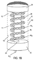
図1A及び図1Bは、固体剤形の薬剤物質のユニットドーズを分与する装置1の実施形態の第1の例を説明する。より詳細には、図1A及び図1Bは、こうした装置の外側図(図1A)及び内側図(図1B)をより詳細に示す。この装置は、固体剤形の薬剤有効物質の複数のユニットドーズを保持するチャンバ11を含む。この例に示すように、チャンバ11は、包囲体の内面10i/包囲体10によって構成、画定、又は具体化される。こうしたチャンバは、図1Bで説明される例に示すように円筒形の形状とすることもできる。図1Bに示された例では楕円形の糖衣錠剤に対応するドーズM1、M2、Miがチャンバ11内に存在する。錠剤(図1Bで参照されるM3)を取り出す及び分与するために、ユーザが指図機構を動かす。図1Bを参照すると、この機構は、有利には蓋又はハンドル20の形態をとる。アクションに応答して、指図機構は、チャンバ11からユニットドーズを取り出す手段をトリガする。したがって、ドーズM3が患者に分与される。有利には、こうしたディスペンサは、分与される時にユニットドーズが投与前に汚れる又は汚染されるリスクを伴って放出されないように、窓付きの受け部30を含んでもよい。
1A and 1B illustrate a first example of an embodiment of an apparatus 1 for dispensing a unit dose of a drug substance in a solid dosage form. More particularly, FIGS. 1A and 1B show an outer view (FIG. 1A) and an inner view (FIG. 1B) of such a device in more detail. The apparatus includes a
図1Bを参照すると、こうした取り出す及び分与するための手段は、有利には、1つ又は複数のユニットドーズを送達するように設計された、円螺旋状に形状設定された中空チューブ28の形態を取ることができる。このチューブは、下底部にオリフィスを有するチャンバ11の内部にあり、チューブの下側遠位部23では、前記オリフィスによって前記チャンバが開放される。こうしたチューブは、チャンバ11の回転軸に実質的に平行な軸を中心に回転するように組み立てることができる。加えて、チューブは蓋又はハンドルと一体にされる。したがって、前記蓋を部分的に又は完全に回転させる行為が、チャンバ内に存在するユニットドーズをチューブ28に沿って動かし、チューブ28がガイドのようにユニットドーズ(すなわちM3)をチャンバのオリフィス13の方に誘導することになるルーチンを引き起こす。こうしたユニットドーズは、したがって、随意的な受け部30を経由してチャンバ11から取り出され、患者に分与される。
Referring to FIG. 1B, such means for removing and dispensing is advantageously in the form of a helically shaped
薬の偽造に対抗するために、より詳細には、容器の二次的な、不正な使用を防ぐために、本発明によれば、装置1の包囲体10は、その最初の充填後にチャンバ11を不可逆的に包囲するように設計することができ、これにより、チャンバのどのような再充填も不可能にする。
In order to combat drug counterfeiting, and more particularly to prevent secondary, unauthorized use of the container, according to the present invention, the
図1Aを参照すると、こうした包囲体10は、例えば熱成形することができる。一変形では、これは、相互に溶着又は接着することができる複数の部品の組立体から得ることができる。各部品は、組立段階の終了によってすべての部品がユニットドーズのための単一のユニット又は閉じ込めチャンバを形成するように、不可逆的な取付けのための手段(例えばクリップ)を含むこともできる。
Referring to FIG. 1A, such an
本発明に係る装置を不正な様態で使用することを試みるには、チャンバ11にアクセスするのに包囲体の完全な状態を変更することが必要となる。好ましい実施形態によれば、こうした包囲体10は、これを破る何らかの試みがなされる場合に前述の試みを示す又は証明する手段を備えることができる。包囲体10は、例えば、外面10e上に印刷された又は彫り込まれた一連の編み縄模様モチーフを有することもできる。代替的に又は加えて、包囲体10はまた、その特徴又は構造により、包囲体に不正開封の試みがなされる時に、包囲体の物理的構造に与えられるどのような損傷も自動的に際立たせる、脆弱領域又は弱い破壊域を有することができる。加えて又は一変形として、試みられた不正開封に反応して、例えば、インク噴射システムによって、チャンバを、ユニットドーズを保持するのに不適合にする、他の技術を用いることもできる。本発明は、包囲体10の完全な状態への不正開封の何らかの試みを示すこれらの方法の例だけに限定されない。図1Aで説明される例によれば、その最初の充填後にこのように形成された包囲体は、所望のパッケージ、装置の計画された使用、必要とされる仕様、又は地方条例に従って、剛性、可撓性、又は半硬質であってもよい。したがって、プラスチック、金属、ポリマーなどの任意のタイプの材料を用いることができる。
In order to attempt to use the device according to the invention in an unauthorized manner, it is necessary to change the complete state of the enclosure in order to access the
包囲体、ひいてはチャンバ11は、図1A及び図1Bで説明されるように実質的に円筒形とすることができる。一方又は他方の変形は、他の幾何学的構成、例えば、円錐、多角形の断面を有する立体、半月形の断面を有する立体などで提示することができる。
The enclosure, and thus the
図1Bで説明される例によれば、チャンバは、包囲体10の内壁10iによって直接画定される。包囲体のライニング材料とユニットドーズとのどのような相互作用も防ぐために、包囲体10の内壁10iは、有利には、複数の保護層、例えば、食品用ワニスを備えることができる。したがって、チャンバ11の内容物に対する包囲体の内面の最適な中立性が確保される。
According to the example described in FIG. 1B, the chamber is defined directly by the inner wall 10 i of the
一変形として、チャンバ11は、包囲体10内に封入することができるインサート、例えば、スリーブ、カートリッジ、又はカセット(図1Bには図示せず)からなることができる。インサートには、最初にユニットドーズが充填される。この変形は、特に、ユニットドーズのバッチ構成、すなわちインサートへの充填を、最終パッケージステップ、すなわち本発明に係る装置の組み立てから分離することを可能にする。この変形はまた、包囲体材料とユニットドーズとのどのような相互作用も防ぐべく包囲体の内面上にどのような保護材料も堆積させる必要性をなくす。ユニットドーズはインサートによって保護される。
As a variant, the
大気中の湿度の高い国々又は領域での一部の薬剤の分与は困難なことがある。湿気に曝されると、特定の薬の活性成分、コーティングの品質、又は分散性錠剤の完全な状態が湿気に曝されるとすぐにダメージを受けることがある。本発明に係る装置のチャンバに格納されたユニットドーズを保護するために、チャンバはまた、有利には、周囲の水分を隔離するべく湿気を吸収する手段12をさらに収容することができ、これにより、チャンバ11内の乾燥雰囲気を維持する。図1Bで説明される例によれば、チャンバ11の上側部分は、周囲の湿気又はチャンバの内部の結露を隔離又は吸収する吸取り紙又は任意の他の材料のストリップを備える。加えて又は代替的に、こうした手段は、装置1内の他の地点に埋め込むこともできる。
Dispensing some drugs in humid countries or regions in the atmosphere can be difficult. When exposed to moisture, the active ingredients of certain drugs, coating quality, or the complete state of dispersible tablets may be damaged as soon as exposed to moisture. In order to protect the unit dose stored in the chamber of the device according to the invention, the chamber can also advantageously contain further means 12 for absorbing moisture in order to isolate ambient moisture, thereby The dry atmosphere in the
補足として、本発明に係る装置はまた、ユニットドーズが分与されていないことを示す手段を含むことができる。網羅的でない例として、こうした手段は、ユニットドーズの分与を阻止するストッパ、例えば、装置のユーザによく見える膜シールからなってもよい。有利には、こうしたストッパは、前記受け部のウィンドウを覆い隠すべく受け部30と協働してもよい。これは、代替的に包囲体と協働する、又は前記包囲体への延長部又は付属物を構成することができる。前記ストッパのレイアウトは、有利には、その取り外しがユーザに見えることになる及び見えたままであるように設計される。例えば、ストッパの取り外しは、ユーザが、装置が既に使用されていることを一目で確認できるように、包囲体又は受け部上に可視の損傷を残すことができる。一変形では又は補足として、ユニットドーズの何らかの以前の分与の存在を示す前記手段は、ユニットドーズの分与をトリガするためにユーザが動作する指図機構20をロックするように設計された機構又は付属物からなることができる。したがって、第1のユニットドーズを送達するには、指図機構を解放するべく前記ロックを外すことが必要となる。例えば、こうした手段は、パッチ又は接着剤ストリップからなることができ、その除去は、有利には、必須ではないが、その支持体上に可視の断片を残すことができ、又は代替的に、例えば蓋又はハンドル20、及び装置の包囲体又は本体と一緒に協働するストリップを残すことができる。
As a supplement, the device according to the invention can also include means for indicating that no unit dose is dispensed. As a non-exhaustive example, such means may consist of a stopper that prevents the dispensing of unit doses, for example a membrane seal that is visible to the user of the device. Advantageously, such a stop may cooperate with the receiving
図2Aは、本発明に係る装置1の第2の実施形態を説明する。こうした装置は、複数のユニットドーズM1〜Miを収容するためにチャンバ11を備える。装置1は、有利には、2つ又は3つの階層若しくはモジュールからなる。上側の階層E1は、凹形の下底部E1bを有する中空シリンダからなる。前記下底部の空洞に開口部13が存在し、その形状はユニットドーズの形状と実質的に適合する。さらに、図2Aで説明される例によれば、階層E1の下底部は、前記開口部13又は下底部上の逆円錐の先端部が前記階層の内壁によって構成されるチャンバの回転軸a11に対してオフセットされるようにレイアウトされる。ユニットドーズは、階層E1の上側開口部E1hでチャンバ11の内部に配列できる。チャンバにユニットドーズが充填されると、チャンバ11の上側区域が蓋14で封止される。蓋14は、溶着、グルー、クリップなどを通じて結合されてもよい上側部分E1hと不可逆的に協働する。そして、上側の階層E1の内壁によって構成されるチャンバ11は、1つだけの開口部、すなわち開口部13を有することになる。
FIG. 2A illustrates a second embodiment of the device 1 according to the present invention. Such an apparatus includes a
チャンバ11の内部の乾燥雰囲気を維持するために、蓋14は、吸取り紙などの周囲の湿気を吸収する手段を含むことができる。加えて、チャンバ11の内部の前記ユニットドーズ間の衝突を防ぐために、蓋14は、一組の螺旋ウィック15又はばね、弾性ファイバなどの任意の他の等価なシステムを備えることができ、その機能は、チャンバ11の頂部に位置するユニットドーズに十分な圧力をかけることである。徐々に、ユニットドーズは、互いに寄りかかっていき、動かなくなる。図2Aに示すように、有利には、圧力ディスク16を前記螺旋ウィック15とユニットドーズとの間に挿入することができ、その下面(すなわちユニットドーズと接触している面)は、螺旋ウィック15とユニットドーズとのどのような直接接触も防ぐために不活性コーティングを有する。一変形として、圧力ディスク16は、すべて不活性コーティング又は材料で作製することができる。図1Bで説明される装置1に関しては、チャンバ11の内面は保護ワニスで被覆することができる。
In order to maintain a dry atmosphere inside the
こうした上側の階層のレイアウトでは、ユニットドーズは、装置が多かれ少なかれ垂直な位置に保持される時に重力及び螺旋ウィックの影響によってチャンバ11の開口部13の方に自然に押される。
In such an upper level layout, the unit dose is naturally pushed towards the opening 13 of the
装置1は第2の階層E2を備え、その機能は、チャンバ11内に収容された複数のユニットドーズのうちの1つのユニットドーズを取り出すこと、及び、取り出されたドーズを患者又はより一般には装置1のユーザに分与することである。
The device 1 comprises a second tier E2, whose function is to take out one unit dose of the plurality of unit doses contained in the
装置1が多かれ少なかれ垂直に保持される時に階層E1よりも下にある階層E2は、チャンバ11の回転軸a11に実質的に平行な分与チャネル25を含む。前記チャネル25の回転軸a25はまた、開口部13の断面に垂直な軸a13に実質的に平行である。軸a13及び軸a25は、チャネル25が開口部13の真向かいにならないようにオフセットされる。軸a13と軸a25との間の距離は、チャンバ11内のユニットドーズの最大寸法よりも大きいか又はこれに等しい。図2Aで説明される例との関連においては、階層E2は、階層E1の外径と実質的に同一の外径を有するシリンダのように見える。
The hierarchy E2, which is below the hierarchy E1 when the device 1 is held more or less vertically, includes a dispensing
階層E2の上側部分は、階層E2の回転軸に垂直な横溝29をさらに備える。溝29はまた、前記溝29に出るチャネル25と交わる。こうした溝29は、一方の端でのみ開口し、指図機構20がそれに沿ってスライドすることができる溝を構成する。円形の断面を有する溝29に関して、機構20は、有利には、前記ハウジング内にスライドするように配置されたフルシリンダのように見える。ハウジング及び機構20は、円形ではないが該機構をハウジングの内部にスライドさせることができるように適合され得る断面を有することができる。指図機構20は、その遠位部21が突き出たままであるように十分長い。機構20は、有利には、その経路が溝29内に制限されるようにショルダ20aを含むことができ、ショルダは階層E2の内面に対する止め部として作用する。したがって、指図機構20は、装置1の組み立て後に取り外すことはできない。溝29はまた、階層E2の内面及び指図機構20の近位部(すなわち内部)と協働するばね又はシリンダ26を特徴とする。したがって、指図機構20はプッシュボタンに似ており、階層の内部でのその経路は、ショルダ20a及びばね26の抵抗によって制限される。指図機構20は、有利には、開口部13の断面と類似した断面を有する横凹部20eとは別の全体構造を有する。したがって、クレードルのように、機構20はユニットドーズを溝29の内部に運ぶことができる。横凹部は、機構20がその休止位置にあり(ショルダ20aが階層E2の内面に対して止まるまでばね26が前記機構を押し戻す)、かつ、階層E1が階層E2よりも上に位置付けられるように装置1が保持される時に、単一のユニットドーズが重力によってチャンバ11から取り出され、前記凹部の中に受け入れられるようにレイアウトされる。
The upper part of the level E2 further includes a
指図機構が装置1のユーザによって作動される時に、前記機構20は溝29に入り、ばね26を引き伸ばす。横凹部20eがユニットドーズを搬送し、ユニットドーズは溝29の下壁上に載る。凹部20eがチャネル25の真向かいにある時に、単純に重力によってユニットドーズが解放され且つ分与される。指図機構20の通過中に、チャンバ11の開口部13が指図機構20の本体によって阻止される。装置のユーザが指図機構20を解放する時に、ばね26がこれをその休止位置に押し戻す。次に、機構20の本体がチャネル25を阻止する。チャンバの開口部13が再び凹部20eの真向かいになり、したがって、ユニットドーズを凹部20e内で生じさせることができる。確実に1つだけのユニットドーズを運ぶことができるようにするために、凹部20eの高さは1つのユニットドーズの高さに近い。
When the instruction mechanism is actuated by the user of the device 1, the
階層E1及び階層E2を一緒に接合又は封止するために、前記階層は、有利には、不可逆の適合する接合点を含む。したがって、階層E1の下部と階層E2の上部は、例えば溶着、グルー、クリップなどの手段を用いて不可逆的な様態で互いに協働するようにレイアウトされる。階層E1及び階層E2のそれぞれの外壁、並びに上側蓋14の外壁が、装置1の包囲体10を構成する。したがって、チャンバ11だけでなくユニットドーズを取り出す及び分与するシステムも包囲される。
In order to join or seal layer E1 and layer E2 together, the layer advantageously includes an irreversible matching junction. Therefore, the lower part of the hierarchy E1 and the upper part of the hierarchy E2 are laid out so as to cooperate with each other in an irreversible manner using means such as welding, glue, and clips. The outer wall of each of the hierarchy E1 and the hierarchy E2 and the outer wall of the
取り出され、分与されるドーズがそのまま落下しないように、装置1は受け部30を含んでもよい。これは、装置1の下側階層E3を構成する。相互に不可逆的に組み立てられる他の2つの階層とは対照的に、受け部30は、例えば受け部を定位置に保つのに十分な摩擦を与えるねじ又は調整部を通じて可逆的に階層E2の下底部と協働する。したがって、ユーザは、受け部30を取り外し、ユニットドーズを回収し、次いで、前記受け部30を階層E2の下底部上に再配置することができる。チャネル25の下部が再び閉鎖される。受け部の使用は、機構の作動をユニットドーズを分与するのに必要とされる第2の動作と関連付けることを可能にする。幼い子供は、これらの2つの連続するアクションを再現することができないはずなので、これにより、保護される。一変形では又は補足として、本発明は、補足的な機構を指図機構20の経路を阻止/解放することと関連付けることができる可能性を提供する。例として、溝29の内部の機構20の経路を解放するべくユーザによって作動可能な割りピン又は第2のプッシュボタン(図2Aには図示せず)が存在してもよい。これは、チャンバ11からユニットドーズを取り出し、前記ユニットドーズを装置1のユーザに分与するのにユーザによる2つの別個のアクションを必要とする混合メタ指図機構を構成する。
The device 1 may include a receiving
こうしたレイアウトは、指図機構の1作動につき1つだけのユニットドーズを分与することができる。複数のユニットドーズを一緒に構成する複数の錠剤又はカプセルを分与するために、寸法、特に、凹部20eが該当数の錠剤又はカプセルを受け入れることができるように凹部20eの深さを単純に調整する。
Such a layout can dispense only one unit dose per actuation of the instruction mechanism. To dispense multiple tablets or capsules that together comprise multiple unit doses, simply adjust the dimensions, particularly the depth of the
チャンバ11の不正な再充填を防ぐために、階層E1及び階層E2、それに加えてもしかすると蓋14との組立体から得られる装置の包囲体は、図1A及び図1Bに係る装置1に言及して上述した手段などの任意の手段を含むことができ、その機能は、どのような不正開封の試みも目立たせる又はさらにはこうした試みによって生じる損傷を増幅させることにある。こうした装置はまた、ユニットドーズがこれまで分与されていないという証拠をもつ手段を含むことができる。したがって、図1A又は図1Bに示される装置の例に続いて、こうした所謂「不正開封防止(tamper−evident)」手段は、有利には、ユニットドーズを分与するためのシャッタ手段からなることができる。単なる例として、こうしたシャッタは、故意に取り外されるまで受け部30と階層E2の下面とを接合するシール又は接着剤ストリップからなることができる。一変形として、ユニットドーズがこれまで分与されていないことを確認するこうした手段はまた、前記付属物が除去又は変更されていない限り指図機構20を阻止する付属物からなることもできる。
In order to prevent unauthorized refilling of the
加えて、チャネル25を介するチャンバの充填を防ぐために、本発明に係る装置は、チャンバ11へのユニットドーズのどのような「戻り」も防ぐ手段を含むことができる。
In addition, in order to prevent filling of the chamber via the
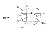
限定ではない例として、こうした手段は、チャンバ11の開口部13又はチャネル25を閉鎖するように設計された1つ又は複数のフラップからなることができる。したがって、特に図2Bで説明されるように、凹部20eの内側近位壁、すなわち、機構20の溝29の内部に残る端に最も近い壁は、フラップ27と協働することができる。この動作は、前記凹部20eの幅にほぼ等しい長さを有する、凹部の上部に位置付けられるピボット連結によって達成できる。こうしたフラップは、最初にチャンバ11に存在するユニットドーズが凹部に入っている時に凹部20eの内壁に対して自然に平らにされた状態に保たれる。ユニットドーズが前記凹部20e又はチャンバの中に存在しない場合であっても、フラップ27は、装置が多かれ少なかれ垂直に保たれる限り、すなわち、階層E1が階層E2よりも上にある時に、凹部の壁に対して平らにされたままである。装置の向きが変化すると、フラップ27は開口部13のすべて又は一部を閉鎖し、装置が垂直に「さかさまに」保持される場合に、すなわち、階層E2が階層E1よりも上に位置付けられる時に、開口部13を完全に閉鎖する。フラップ27の回転は、凹部20e内の対向する内壁上の小さい止め部27’の存在によって制約される。前記止め部27’は、有利には、ユニットドーズが開口部13を通過する及び凹部20e内に入るのを妨げないように配設される。この簡単なフラップ27は、分与チャネル25を介してチャンバ11に充填するどのような試みも防ぐ。こうした動作を達成するには、分与チャネル25の遠位部25bが上に向く状態で装置を逆さまにすること、前記チャネル25に「不正な」ドーズを導入すること、凹部20eがチャネル25の正面に来る、ひいては前記ドーズを凹部20eに導入するように指図機構20を作動させることが必要である。機構20を解放することによって、凹部がチャンバ11の開口部13に位置付けられる。フラップ27は、出てきたユニットドーズと開口部13との間に位置付けられたままである。このユニットドーズはチャンバに入ることはできない。他の技術又はフラップは、ドーズがチャネル25の遠位部25bから溝29の方に移動する時に指図機構20の変位を阻止する又はチャネル25へのドーズの伝達を阻止するように位置付けできる。随意的な受け部30内の雰囲気を乾燥した状態に保つために、湿気及び/又は結露を吸収する手段(図2Aには図示せず)を収容することができる。
By way of non-limiting example, such means can consist of one or more flaps designed to close the
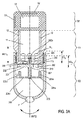
図3Aは、本発明に係るユニットドーズを分与するための装置の第3の実施形態を説明する。実質的に円筒形の中空の第1の階層E1は、ユニットドーズM1、M2、Miを格納するように設計されたチャンバ11を包囲する。シリンダE1はその下底部11bで閉鎖される。前記下底部は、ユニットドーズの寸法に実質的に適合する構成を有する開口部13を有する。階層E1の円筒形の壁の厚さは、階層E1を下側階層E2の上部に挿入することができるような状態で高さE1bにわたって底部の方にテーパする(後述)。階層E1の上部を、蓋を用いて、又は後で分かることとなるように、上側の階層E0によって、閉鎖することができる。前記蓋又は前記随意的な上側の階層E0の下部は、階層E1の上部と協働し、これに恒久的に、溶着、グルー、クリップなどによる不可逆的な連結で封止される。したがって、チャンバ11は階層E1の内面によって画定される。この内壁は、有利には、ユニットドーズとE1を構成する材料との相互作用を防ぐために食品用ワニスの層又は任意の他の保護層を含むことができる。チャンバ11の内壁はまた、チャンバ11内の雰囲気を乾燥させるために湿気又は結露を吸収するある材料の1つ又は複数のストリップ12を含むことができる。
FIG. 3A illustrates a third embodiment of an apparatus for dispensing unit doses according to the present invention. A substantially cylindrical hollow first tier E1 encloses a
階層E1よりも下の階層E2は中空シリンダからなり、その外径は階層E1の上部の外径と実質的に同一である。階層E2の上部の円筒形の壁の厚さは、上述の高さE1bと実質的に等しい高さE2hにわたって減少する。したがって、2つの階層E1及び階層E2は、それぞれ高さE1b及び/又はE2hと実質的に等しい距離にわたってE1の下部がE2の上部に滑り込む状態で協働することができる。階層E2の上側区域上の内部ショルダを、E2の内面とE1の外壁との間に挿入されるばね209を固定するのに用いることができる。このばね209は、両方の階層を相互に押し戻す傾向がある力Fを及ぼす。
The level E2 below the level E1 is formed of a hollow cylinder, and the outer diameter thereof is substantially the same as the outer diameter of the upper part of the level E1. The thickness of the cylindrical wall at the top of level E2 decreases over a height E2h that is substantially equal to the height E1b described above. Thus, the two levels E1 and E2 can cooperate with the lower part of E1 sliding into the upper part of E2 over a distance substantially equal to the height E1b and / or E2h, respectively. An internal shoulder on the upper section of level E2 can be used to secure a
階層E2は、階層E2の回転軸と実質的に直交する4つのアーム204a、204b、204c、204dを有する内部構造体、例えば、星形の構造体をさらに備える。本発明は前記アームの数又はこの構造体の構成に限定されない。前記アームは、実質的に階層E2の回転軸との交差点で出会う。前記アームの接合部も、その回転軸が階層E2の回転軸と実質的に一致するねじれシャフト203との固定連結に従って協働する。前記シャフトは、2つの階層の組み立て後に階層E1のチャンバ11内部の開口部を通して出ることができるような長さである。各アーム204a〜204dは、ねじれシャフト203の方向に近い方向をたどる突き出たラグを有する。
The hierarchy E2 further includes an internal structure having four
本発明によれば、チャンバ11の開口部13と類似した開口部213を有するディスク201は、ねじれシャフト203上で回転するように設置されるはずである。ディスク201は、階層E1の下底部11bの外壁に実質的に当接するようにシャフト203上に位置付けられる。シャフト203の周りのコイルばね207は、ディスク201を、ねじれシャフト203に沿ってスライドするように階層E1の下底部に対して実質的に平らにされた状態に保つ。前記ディスク201の下側、すなわち階層E1とは反対側の側部は、階層E2における星形の構造体上のアームと同数の(この例では4つの)凹部202を備える。各凹部202は、ラグ又は突起205a〜205dの遠位部を受け入れるようにレイアウトされ、前記ラグの長さは、ばね209が収縮する時にそれらの遠位部が凹部202とのみ協働するように設定される。有利には、前記ばね207のそれぞれの端は、凹部202を突起205a〜205dと位置合わせされた状態に保つために、一方の側部でディスク201に及び他方の側部でねじれシャフト203の下底部に接合される。シャフト203の遠位部は、組み立て後に、例えば、階層E1の下面の適切な開口部と協働する、シャフト203の遠位部上の1つ又は複数の長手方向のラグ又は突き出たストッパ206によって、チャンバ11の下部に固定される。こうしたE1及びE2のレイアウトは、階層E2の上部における階層E1の下部の第1の「スライド」型のMVT1移動を可能にする。シャフト203はガイドとして作用する。これはまた、チャンバ11内に出るシャフト203の端に位置する止め部206bによって階層E1の経路を制約する。図3A及び図3Bで説明されるE1及びE2の配置はまた、階層E1に対する階層E2の第2の回転型のMVT2移動を可能にする。実際には、ねじれシャフト203は、例えばユーザのアクションを通じてこのMVT2移動を可能にする。ねじれシャフト203は、ユーザが機構を解放するとすぐにシャフトによって及ぼされるばね機能により階層E1及び階層E2を自動的に相対的な休止位置にする。
According to the present invention, a
ディスク201の開口部213は、チャンバ11の開口部13と類似し、有利には、前記シャフトの開口部13を隔てる距離又は半径に実質的に等しいシャフト203の距離又は半径で位置する。対照的に、ディスク201は、最初に、すなわち、階層E1及び階層E2がそれらの相対的な休止位置にある時に、ねじれシャフトが最大ねじれに達し、かつ、ばね209を押し込むのに十分な圧力の影響下で凹部202に入っているラグ204a〜205dによってディスク201が阻止される時にのみ開口部13及び213が互いに向き合うような状態で位置する。したがって、両方の移動MVT1及びMVT2が組み合わされない限り、ユニットドーズをチャンバ11から出し、分与することはできない。したがって、この配置は、介助のない幼い子供がユニットドーズディスペンサを使用するリスクへの打開案を提供する。実際には、ユニットドーズの分与をトリガするのに2つの別個の動作が必要とされる。ユニットドーズは、重力によって取り出され且つ分与され、前記ユニットドーズは、装置が実質的に垂直に保持され、階層E1が階層E2よりも上に位置付けられるという条件が揃っていれば、開口部13を介してチャンバ11の外に出て、開口部13と一時的に位置合わせされた開口部213を通り、アーム205a〜205dを通過して階層E2の下部300に落下する。したがって、指図機構は、本発明との関連では、装置1のユーザによって互いに対して作動可能な2つの階層E1及び階層E2の組み合わせからなる。
The
階層E2は、その下底部300で開口することができる。これは代替的に、取り出したユニットドーズを受け入れることを意図された受け部を形成するべく逆円錐形又はドームの形状を有してもよい。前記ユニットドーズを使用できるようにするために、ユーザは、階層E2の下部の開口部を閉鎖するように設計されたキャップ31を取り外すことができる。E2の下部はまた、受け部300に存在するどのような湿気又は結露も吸収する手段を含むことができる。
The hierarchy E2 can be opened at its
階層E1と階層E2の組立体は、一方ではシャフト203の遠位部に位置する止め部206bを設定又は機械加工することによって、及びカバー又は随意的な上側の階層E0を介して充填された後でチャンバ11の上部を閉鎖することによって、不可逆にすることができる。図3A及び図3Bで説明される装置は、全体として円筒形の構成を有する。一変形として、これは、多角形又は他の形状の断面を有する階層を含むことができる。
After the assembly of level E1 and level E2 has been filled on the one hand by setting or machining a stop 206b located at the distal part of the
偽造対策を改善し、慢性疾患を患っている患者に関する支援サービスの要件を満足し、さらには患者の臨床試験プロトコルの遵守を測るために、本発明に係る装置はまた、そのどのような実施形態も、装置又はさらにはチャンバ内のユニットドーズの組成物に含まれる活性物質を識別するための、又はさらに、ユニットドーズが分与される度にタイムスタンプを付与する及び記録するための電子手段を含んでもよい。 In order to improve anti-counterfeiting, meet the requirements of support services for patients suffering from chronic illnesses, and also measure patient compliance with clinical trial protocols, the device according to the invention is also in any embodiment thereof The electronic means for identifying the active substance contained in the composition of the unit dose in the apparatus or even in the chamber, or additionally for providing a time stamp and recording each time the unit dose is dispensed May be included.
こうした電子手段を入れるために、本発明に係る装置は専用の階層を備えることができる。 In order to include such electronic means, the device according to the invention can be provided with a dedicated hierarchy.
図3Aで説明される例は、こうした代替的な実施形態を例示する。これは、指図機構と協働する処理ユニット及び前記処理ユニットを駆動するための電力源を収納又は収容するために特別なハウジング51を有する階層E0を含む。例として、こうした電源は、前記処理ユニットと協働する、前記ハウジング51の中に入れられたバッテリ又は光起電力セル52であってもよい。こうした処理ユニット(図3Aには図示せず)は、有利には、ユニットドーズを取り出す及び分与するシステムをトリガする指図機構の作動ごとにタイムスタンプを付与する及び記録するためにタイマ及びメモリを組み込む。図3Aに示される例を参照すると、階層E1は、シャフト203のねじれを制限するべく下側階層と協働する止め部を含むことができる。処理ユニットは、この接触を、2つの階層E1及び階層E2の組み合わせによって構成される指図機構によって伝送される、ユニットドーズが分与されていることを確認する1つの情報として利用することができる。処理ユニットは、例えば、階層E1と階層E2が処理ユニットによって検出可能な対地又は電気リポジトリを構成することができる止め部による2つの階層間の接触を電気的に伝導する材料で作成される場合に、この情報をリレーするのに任意のプロトコルを用いることができる。
The example described in FIG. 3A illustrates such an alternative embodiment. This includes a hierarchy E0 having a
第2の例によれば、図2Aで説明される装置1は、ユーザによって機構20に及ぼされる力を検出するために実行終了センサを搭載することができる。こうしたセンサは溝29に位置できる。前記センサが機構20の近位部によって要求されるとすぐに、すなわちユーザが前記機構20を溝29に押し込んだ時に、前記実行終了センサは送達情報を処理ユニットに伝送する。
According to the second example, the device 1 described in FIG. 2A can be equipped with an execution end sensor to detect the force exerted on the
一変形として、ユニットドーズを取り出す及び分与する手段は、それ自体でユニットドーズの分与を検出するセンサを含むことができる。図3A及び図3Bで説明される例によれば、こうした光学センサ又は誘導型センサは、開口部213に近いディスク201上に存在することができる。この変形によれば、処理ユニットは、もはや指図機構と直接協働しないが、ユニットドーズが開口部213を通るとすぐに情報を伝送する前記センサと協働する。
As a variant, the means for taking and dispensing the unit dose may comprise a sensor that itself detects the dispensing of the unit dose. According to the example described in FIGS. 3A and 3B, such an optical sensor or inductive sensor can be present on the
どの解決策が選ばれても、処理ユニットは、ユニットドーズが分与される度にタイムスタンプを付与する及び記録することができる。 Whatever solution is chosen, the processing unit can give and record a time stamp each time a unit dose is dispensed.
ハウジング51の完全な状態及びこの内部のすべての構成要素を保つために、本発明によれば、本発明に係る装置の包囲体は、有利には、チャンバ11及び前記ハウジング51を包囲することができる。このために、図3Aを参照すると、階層E1と階層E0を、固定される不可逆的な連結を介して、例えば、溶着、グルー、クリップなどによって封止する、すなわち協働させることができる。この包囲体は、2つの階層E0及びE1の外壁によって具体化される。チャンバ11を覆い、これにより閉鎖するための階層E0の選択は、特別な蓋の必要性をなくす。階層E1と階層E0の組立体から得られる前記包囲体は、図1A及び図2Aを参照して説明される上記の実施形態について前述したようにどのような不正開封の試みも証明する又はさらには増幅させる任意の適切な手段を収容することができる。ハウジング51は、有利には、前記ハウジング内の湿気及び結露に対して電子部品を保護するために非導電性樹脂又は発泡体を収容することができる。
In order to maintain the integrity of the
本発明に係る装置内に収容される処理ユニットのメモリの内容を利用できるようにするために、前記処理ユニットは、有利には、外の世界と通信するために無線通信インターフェースを含むことができる。一変形では又は補足として、処理ユニットは、外の世界と通信するために配線接続される通信インターフェースを含むことができる。このように、適切なヒューマンマシンインターフェースを通じて記憶されている又は処理ユニットによって生成された情報を収集し、処理し、送り返すために、リーダ又は端末との通信を確立することができる。リーダ又は端末は、装置の処理ユニットとの通信プロトコルを実装することができるであろう。 In order to be able to use the contents of the memory of the processing unit contained in the device according to the invention, the processing unit can advantageously include a wireless communication interface for communicating with the outside world. . In one variation or supplement, the processing unit may include a communication interface that is wired to communicate with the outside world. In this way, communication with a reader or terminal can be established to collect, process and send back information stored through a suitable human machine interface or generated by a processing unit. The reader or terminal could implement a communication protocol with the processing unit of the device.
したがって、処理ユニットのメモリに記録された特定の情報、例えば、それぞれ、装置専用の、及びチャンバに最初に充填したオペレータ(例えば、薬剤のユニットドーズをパッケージすることを担当する製薬会社又は任意の下請業者)専用の、第1の識別子及び第2の識別子、又は代替的に、チャンバ内に収容された固体剤形の活性物質を特徴づける識別子を調べることによって本発明に係る装置を追跡することができる。 Thus, certain information recorded in the memory of the processing unit, eg, the operator dedicated to the device and the first filling of the chamber (eg, the pharmaceutical company responsible for packaging the unit dose of the drug or any subcontractor, respectively). Tracking a device according to the invention by examining a dedicated first identifier and a second identifier, or alternatively an identifier characterizing the active substance of the solid dosage form contained in the chamber it can.
ユニットドーズの分与の履歴を回収することも可能である。 It is also possible to collect the unit dose distribution history.
本発明に係る装置は、メモリに記録された又は処理ユニットによって生成された情報を送り返すことができる特定のヒューマンマシンインターフェースを含むことができ、処理ユニットは前記ヒューマンマシンインターフェースを制御する。例として、図3Aで説明される装置1は、フレキシブルディスプレイ53、例えば、LCD画面を含むことができる。好ましい変形によれば、処理ユニットは、特別なコマンドボタンを通じたユーザによる要求に応答して、又は場合により、所定数のユニットドーズの分与動作の後で、可逆ハッシュ関数又は圧縮関数を実行することができる。装置と通信することができる電子リーダ又は端末(一部の顧客にとっては費用がかかりすぎる場合がある)の代わりに、メモリ内の又は処理ユニットによって生成された情報は、人間が収集し、例えば特にユニットドーズの分与の履歴とリンクさせることができる。これを行うために、ユーザは、装置のヒューマンマシンインターフェース53を調べることによって、ユーザの労力、及び不正確な情報を戻すリスクを制限するべく、好ましくは4〜16文字の短い英数字コードを読み取る。ユーザは、次いで、このコードを電話、ファックス、電子メールなどによって通信することができる。本発明によれば、ヒューマンマシンインターフェースは、加えて又は代替的に、スピーカ又はより一般には人間が情報を知覚することを可能にする任意の手段からなってもよい。本発明によれば、処理ユニットとのすべての通信は、従来の技術を通じて、例えばコーディング及び/又は署名及び/又は認証などによって保護されるべきである。
The apparatus according to the invention can include a specific human machine interface that can send back information recorded in memory or generated by a processing unit, which controls the human machine interface. As an example, the device 1 described in FIG. 3A can include a
本発明に係る装置の悪意のある二次使用の可能性を排除するために、又は装置に収納された処理ユニットのメモリの内容を変更するどのような試みも防ぐために、前記メモリを、有利には、消去不能となるように設計することができる。 In order to eliminate the possibility of malicious secondary use of the device according to the invention, or to prevent any attempt to change the contents of the memory of the processing unit housed in the device, said memory is advantageously Can be designed to be non-erasable.
処理ユニットが特にユニットドーズの分与の履歴を生成するように、本発明はまた、本発明に係る装置の処理ユニットによって実施されるプロセスに関する。こうしたプロセスは、特に、チャンバから出され、分与されるすべてのユニットドーズにタイムスタンプを付与するステップを含む。これを行うために、処理ユニットは、ユニットドーズの分与をトリガする指図機構又はこうした分与を検出するセンサと協働する。処理ユニット内のクロックの存在は、分与動作にタイムスタンプを付与することを可能にする。タイムユニットのカウンタを増分するべく処理ユニットによって使用可能な例えばリファレンス又は任意の他のリファレンスとしてGMTを用いる任意のタイムスタンプ技術を採用することができる。処理ユニットはまた、処理ユニットのメモリの内容、例えば分与履歴から生成された情報をエンコードし、外の世界に伝送するステップを含むプロセスを実施することができる。 The invention also relates to a process carried out by the processing unit of the apparatus according to the invention so that the processing unit generates a distribution history of unit doses in particular. Such a process specifically includes the step of time stamping all unit doses that are removed from the chamber and dispensed. To do this, the processing unit cooperates with an instruction mechanism that triggers the dispensing of unit doses or a sensor that detects such dispensing. The presence of a clock in the processing unit makes it possible to give a time stamp to the dispensing operation. Any time stamp technique can be employed that uses GMT as a reference or any other reference that can be used by the processing unit to increment the time unit counter, for example. The processing unit can also implement a process that includes encoding the contents of the processing unit's memory, eg, information generated from a dispensing history, and transmitting it to the outside world.
処理ユニットがこうしたプロセスを実施できるように、その初期化又はプログラミングは、有利には、処理ユニットによって解釈又は実行される時に前述のプロセスを立ち上げる1つ又は複数のプログラム命令を含むコンピュータソフトウェアを含むことができる。こうしたソフトウェアは、装置の組み立て時に又はその個人設定プロセス中に、処理ユニットと協働するメモリにダウンロードする又は予めロードすることができる。 In order for the processing unit to be able to carry out such a process, its initialization or programming advantageously comprises computer software comprising one or more program instructions that launch said process when interpreted or executed by the processing unit. be able to. Such software can be downloaded or preloaded into memory cooperating with the processing unit during assembly of the device or during its personalization process.
Claims (25)
前記包囲体(10、10a)が、
前記チャンバ(11)を不可逆的に包囲し、
前記包囲体の完全な状態の変更中に前記変更を証明する、目立たせる、又は際立たせる手段を備え、
取り出す及び分与する手段が、前記ユニットドーズが前記チャンバ(11)の中に戻ることを防ぐ手段(27)を含むことを特徴とする、装置。 A chamber (11) containing a plurality of unit doses (M1, M2,..., Mi) containing an active substance, an instruction mechanism (20) operable by a user, and an operation of the instruction mechanism (20) by the user In response to the means (28, 20e, 25) for removing a single unit dose (M3) of the plurality of doses stored in the chamber (11) from the chamber and dispensing the single dose. 201) and an enclosure (10, 10a) cooperating with the chamber (11) for dispensing a unit dose (M3) of an active substance in solid pharmaceutical form,
The enclosure (10, 10a)
Irreversibly surrounding the chamber (11),
Means for proving, highlighting or highlighting the change during a change in the complete state of the enclosure;
The apparatus characterized in that the means for removing and dispensing includes means (27) for preventing the unit dose from returning into the chamber (11).
前記装置が、前記センサと協働する処理ユニットを受け入れるハウジング(51)と、前記処理ユニットの動作に必要な電気エネルギーを供給する電源とを含み、前記ユニットがまた、前記センサによって検出されるユニットドーズの各送達にそれぞれタイムスタンプを付与する及び記録するクロック及びメモリを備える、請求項1〜8のうちいずれか一項に記載の装置。 The means for removing and dispensing comprises a sensor for detecting dispensing of unit dose;
The apparatus includes a housing (51) that receives a processing unit cooperating with the sensor, and a power source that supplies electrical energy required for operation of the processing unit, the unit also being detected by the sensor 9. Apparatus according to any one of the preceding claims, comprising a clock and memory for time stamping and recording each delivery of dose.
前記処理ユニットのメモリの内容から生成された情報をエンコードし、外の世界に戻すステップと、を含むことを特徴とする、請求項18〜23のうちいずれか一項に記載の装置の処理ユニットによって実施されるプロセス。 Time stamping each unit dose removed from the chamber and dispensed;
24. The processing unit of the apparatus according to any one of claims 18 to 23, comprising encoding information generated from the contents of the memory of the processing unit and returning it to the outside world. The process carried out by.
Applications Claiming Priority (3)
| Application Number | Priority Date | Filing Date | Title |
|---|---|---|---|
| FR1356651 | 2013-07-05 | ||
| FR1356651A FR3007969B1 (en) | 2013-07-05 | 2013-07-05 | DISPENSER OF A UNITARY DOSE OF AN ACTIVE SUBSTANCE UNDER A SOLID GALENIC FORM |
| PCT/FR2014/051705 WO2015001262A1 (en) | 2013-07-05 | 2014-07-03 | Dispenser for dispensing a unitary dose of an active substance in a solid dosage form |
Publications (2)
| Publication Number | Publication Date |
|---|---|
| JP2016526427A true JP2016526427A (en) | 2016-09-05 |
| JP2016526427A5 JP2016526427A5 (en) | 2017-08-17 |
Family
ID=49667297
Family Applications (1)
| Application Number | Title | Priority Date | Filing Date |
|---|---|---|---|
| JP2016522719A Pending JP2016526427A (en) | 2013-07-05 | 2014-07-03 | Dispenser for dispensing unit dose of active pharmaceutical substance in solid dosage form |
Country Status (8)
| Country | Link |
|---|---|
| US (1) | US9975688B2 (en) |
| EP (1) | EP3016867B1 (en) |
| JP (1) | JP2016526427A (en) |
| CN (1) | CN105473458B (en) |
| CA (1) | CA2916837A1 (en) |
| FR (1) | FR3007969B1 (en) |
| HK (1) | HK1218106A1 (en) |
| WO (1) | WO2015001262A1 (en) |
Families Citing this family (22)
| Publication number | Priority date | Publication date | Assignee | Title |
|---|---|---|---|---|
| FR3007969B1 (en) * | 2013-07-05 | 2016-01-29 | Medicodose Systems | DISPENSER OF A UNITARY DOSE OF AN ACTIVE SUBSTANCE UNDER A SOLID GALENIC FORM |
| FR3017377B1 (en) * | 2014-02-12 | 2017-01-13 | Stiplastics | DEVICE FOR COUNTING AND DISPENSING OBJECTS |
| US10596071B1 (en) * | 2015-09-22 | 2020-03-24 | Michael Song | Locked pill bottle with timed dispense limits |
| US11246805B2 (en) | 2016-08-26 | 2022-02-15 | Changhai Chen | Dispenser system and methods for medication compliance |
| US10722431B2 (en) | 2016-08-26 | 2020-07-28 | Changhai Chen | Dispenser system and methods for medication compliance |
| US20180055738A1 (en) | 2016-08-26 | 2018-03-01 | Changhai Chen | Dispenser system and methods for medication compliance |
| WO2018130664A1 (en) * | 2017-01-13 | 2018-07-19 | Philip Morris Products S.A. | Dispensing device |
| US10683160B2 (en) * | 2017-02-15 | 2020-06-16 | Nypro Inc. | Apparatus, system and method for a pill dispenser |
| FR3070039B1 (en) * | 2017-08-09 | 2019-08-30 | Chanel Parfums Beaute | DEVICE FOR DISPENSING A PRODUCT PRESENT IN THE FORM OF BALLS |
| WO2019038580A1 (en) * | 2017-08-25 | 2019-02-28 | Barbosa De Abreu E Sousa Armando Miguel | Medicament dispenser |
| CN107826445B (en) * | 2017-11-12 | 2019-07-16 | 安徽益顺塑业有限公司 | A kind of medicine bottle |
| CN112654273B (en) * | 2018-07-06 | 2022-06-14 | 宝石C2有限责任公司 | Gemstone applicator assembly |
| CN109157417A (en) * | 2018-09-30 | 2019-01-08 | 翰林航宇(天津)实业有限公司 | A kind of loading amount regulating device |
| US20200130921A1 (en) * | 2018-10-26 | 2020-04-30 | Serv Goyal | Bag container system |
| US11154460B2 (en) * | 2018-12-10 | 2021-10-26 | International Business Machines Corporation | Personal prescription dispenser |
| EP3674233A1 (en) * | 2018-12-27 | 2020-07-01 | Clariant Plastics & Coatings Ltd | A tablet dispensing device |
| US11267643B2 (en) * | 2019-01-22 | 2022-03-08 | Coopervision International Limited | Contact lens dispenser |
| CN109573353B (en) * | 2019-01-29 | 2024-02-20 | 王伟 | Nut storage and taking device for automobile maintenance |
| EP3692844A1 (en) * | 2019-02-07 | 2020-08-12 | Nerudia Limited | Smoking substitute apparatus |
| CN111573017B (en) * | 2020-05-08 | 2022-01-28 | 安阳工学院 | Intelligent device for helping old people to take medicine |
| CN113071815A (en) * | 2021-03-26 | 2021-07-06 | 张交腾 | Nitroglycerin light-resistant medicine storage bottle for cardiovascular internal medicine |
| US11707163B2 (en) * | 2021-06-14 | 2023-07-25 | Angelo Masino | Dispensers and related devices and methods for mounting dispensers |
Citations (10)
| Publication number | Priority date | Publication date | Assignee | Title |
|---|---|---|---|---|
| US3889847A (en) * | 1973-11-01 | 1975-06-17 | Afa Corp | Child-resistant pill dispenser |
| US4154365A (en) * | 1976-09-30 | 1979-05-15 | Antonio Lorca | Dispensing container |
| US4560086A (en) * | 1983-09-21 | 1985-12-24 | Israel Stol | Helical elevating dispenser for round objects such as candies |
| US4611727A (en) * | 1985-02-20 | 1986-09-16 | Graff James C | Solid oral dosage dispenser with safety, tamper-proof and sanitation features |
| JPS63232181A (en) * | 1987-01-05 | 1988-09-28 | ハイメディックス・インコーポレーテッド | Capsule dispenser |
| US5269413A (en) * | 1992-09-04 | 1993-12-14 | George Stern | Container for pills |
| US5476181A (en) * | 1994-03-15 | 1995-12-19 | Seidler; David | Child-resistant product dispenser |
| WO2007081947A2 (en) * | 2006-01-06 | 2007-07-19 | Acelrx Pharmaceuticals, Inc. | Drug storage and dispensing devices and systems comprising the same |
| JP2009280281A (en) * | 2008-04-24 | 2009-12-03 | Taisei Kako Co Ltd | Tablet cushioning material |
| WO2011154018A1 (en) * | 2010-06-08 | 2011-12-15 | Csp Technologies, Inc. | Tablet dispenser |
Family Cites Families (24)
| Publication number | Priority date | Publication date | Assignee | Title |
|---|---|---|---|---|
| US3785525A (en) * | 1972-01-31 | 1974-01-15 | Safe Well Mfg Co | Chemical tablet dispensing device for wells |
| US3927484A (en) * | 1974-02-04 | 1975-12-23 | Gilbreth Co | Die-cut coupon shrink label |
| US4150766A (en) * | 1977-03-18 | 1979-04-24 | Knorr Robert H | Dispensing apparatus |
| US4273254A (en) * | 1979-01-23 | 1981-06-16 | Brian Cuppleditch | Device for containing and dispensing particles such as tablets |
| NL8200666A (en) * | 1982-02-19 | 1983-09-16 | Philips Nv | TRANSMISSION CIRCUIT FOR AN ELECTRONIC TELEPHONE. |
| US5176290A (en) * | 1991-10-17 | 1993-01-05 | Machine-O-Matic Limited | Coin operated vending machine |
| US5833117A (en) * | 1996-04-15 | 1998-11-10 | Parkway Machine Corporation | Dynamic vending machine with track insert assembly |
| FR2758536B1 (en) * | 1997-01-21 | 2001-01-26 | Velfor Plast Sa | DISPENSER PACKAGING OF STORED PRODUCTS AND PRODUCTS |
| DE19737747A1 (en) * | 1997-08-29 | 1998-02-05 | Schulz Rolf A Dipl Kaufm | Dropper chute tablet dispenser |
| US6729330B2 (en) * | 1998-05-05 | 2004-05-04 | Trudell Medical International | Indicating device for aerosol container |
| GB0216831D0 (en) * | 2002-07-19 | 2002-08-28 | Glaxo Group Ltd | Medicament dispenser |
| CA2405361A1 (en) * | 2002-09-26 | 2004-03-26 | Beaver Machine Corporation | Bulk vending machine |
| GB0328859D0 (en) * | 2003-12-12 | 2004-01-14 | Clinical Designs Ltd | Dispenser and counter |
| US7175046B2 (en) * | 2004-06-21 | 2007-02-13 | Shen-Hao Yao | Merchandise output device of a vending machine |
| CN106727271B (en) * | 2006-01-06 | 2020-02-14 | 阿塞尔Rx制药有限公司 | Small volume oral transmucosal dosage form |
| CN201002842Y (en) * | 2007-01-12 | 2008-01-09 | 黄杏水 | Round screw sliding board candy box |
| DE202007018407U1 (en) * | 2007-03-16 | 2008-07-10 | Pöppelmann Holding GmbH & Co. KG | donor |
| JP5156824B2 (en) * | 2007-04-11 | 2013-03-06 | メディクペン アーベー | Tablet dispenser system |
| EP2231098A2 (en) * | 2007-12-21 | 2010-09-29 | DSM IP Assets B.V. | Device for dispensing solid preparations |
| CN202072133U (en) * | 2011-05-14 | 2011-12-14 | 林旭捷 | Quantitative pouring-out tablet bottle |
| CN202244708U (en) * | 2011-09-19 | 2012-05-30 | 林旭捷 | Tablet quantifying device |
| CN202777062U (en) * | 2012-09-19 | 2013-03-13 | 王兴林 | Medicine bottle capable of realizing automatic tablet/granule outgoing |
| DE202012009997U1 (en) * | 2012-10-19 | 2012-11-23 | Petra Claudia Bopp | Feed dispenser and carrying device |
| FR3007969B1 (en) * | 2013-07-05 | 2016-01-29 | Medicodose Systems | DISPENSER OF A UNITARY DOSE OF AN ACTIVE SUBSTANCE UNDER A SOLID GALENIC FORM |
-
2013
- 2013-07-05 FR FR1356651A patent/FR3007969B1/en active Active
-
2014
- 2014-07-03 CA CA2916837A patent/CA2916837A1/en not_active Abandoned
- 2014-07-03 JP JP2016522719A patent/JP2016526427A/en active Pending
- 2014-07-03 WO PCT/FR2014/051705 patent/WO2015001262A1/en active Application Filing
- 2014-07-03 US US14/902,413 patent/US9975688B2/en not_active Expired - Fee Related
- 2014-07-03 EP EP14747078.5A patent/EP3016867B1/en active Active
- 2014-07-03 CN CN201480046378.3A patent/CN105473458B/en not_active Expired - Fee Related
-
2016
- 2016-05-09 HK HK16105227.6A patent/HK1218106A1/en unknown
Patent Citations (10)
| Publication number | Priority date | Publication date | Assignee | Title |
|---|---|---|---|---|
| US3889847A (en) * | 1973-11-01 | 1975-06-17 | Afa Corp | Child-resistant pill dispenser |
| US4154365A (en) * | 1976-09-30 | 1979-05-15 | Antonio Lorca | Dispensing container |
| US4560086A (en) * | 1983-09-21 | 1985-12-24 | Israel Stol | Helical elevating dispenser for round objects such as candies |
| US4611727A (en) * | 1985-02-20 | 1986-09-16 | Graff James C | Solid oral dosage dispenser with safety, tamper-proof and sanitation features |
| JPS63232181A (en) * | 1987-01-05 | 1988-09-28 | ハイメディックス・インコーポレーテッド | Capsule dispenser |
| US5269413A (en) * | 1992-09-04 | 1993-12-14 | George Stern | Container for pills |
| US5476181A (en) * | 1994-03-15 | 1995-12-19 | Seidler; David | Child-resistant product dispenser |
| WO2007081947A2 (en) * | 2006-01-06 | 2007-07-19 | Acelrx Pharmaceuticals, Inc. | Drug storage and dispensing devices and systems comprising the same |
| JP2009280281A (en) * | 2008-04-24 | 2009-12-03 | Taisei Kako Co Ltd | Tablet cushioning material |
| WO2011154018A1 (en) * | 2010-06-08 | 2011-12-15 | Csp Technologies, Inc. | Tablet dispenser |
Also Published As
| Publication number | Publication date |
|---|---|
| EP3016867B1 (en) | 2018-04-04 |
| EP3016867A1 (en) | 2016-05-11 |
| FR3007969A1 (en) | 2015-01-09 |
| CA2916837A1 (en) | 2015-01-08 |
| CN105473458A (en) | 2016-04-06 |
| US20160207691A1 (en) | 2016-07-21 |
| HK1218106A1 (en) | 2017-02-03 |
| FR3007969B1 (en) | 2016-01-29 |
| WO2015001262A1 (en) | 2015-01-08 |
| CN105473458B (en) | 2018-05-22 |
| US9975688B2 (en) | 2018-05-22 |
Similar Documents
| Publication | Publication Date | Title |
|---|---|---|
| JP2016526427A (en) | Dispenser for dispensing unit dose of active pharmaceutical substance in solid dosage form | |
| AU2001295771B2 (en) | Dose dispensing apparatus | |
| US9066847B2 (en) | Storage and dispensing devices for administration of oral transmucosal dosage forms | |
| US8038008B2 (en) | Medicament dispenser and associated methods | |
| CN103585021B (en) | Medicament storage and dispensing apparatus and comprise the system of this device | |
| US20150148943A1 (en) | Programmable time motorized tamperproof blister pack dosage dispenser and method of preventing unauthorized use of pharmaceuticals and other items | |
| US7392918B2 (en) | Method and device for pill dispensing | |
| US20120006700A1 (en) | Dispenser | |
| US20080303665A1 (en) | Package-companion-user interactive system and associated method | |
| US11771693B2 (en) | Device for deterring abuse of drugs | |
| JP2019524391A (en) | Smart pack system for drugs | |
| US20100312383A1 (en) | Interactive multifunctional system for packaged-product authentication and real-time product dispensation information | |
| US11743424B1 (en) | Web enabled audiovisual medication dispensing with enhanced compliance verification | |
| WO2019092356A1 (en) | Device for loading/distributing objects in a storage container for such objects, uses of such a device and method for loading and distribution | |
| CA2297363A1 (en) | Pill dispenser with alarm | |
| EP3648729B1 (en) | Cassette for storing and dispensing non-gaseous products and manufacturing method | |
| CA2312418A1 (en) | Assistance process for administration of medications in accordance with a medical prescription and system for applying this process | |
| US20020000917A1 (en) | Pill dispenser with alarm | |
| FR2922441A1 (en) | Drug intake compliance measuring device for patient e.g. vision impaired patient, has measurement unit for measuring overall impedance of conducting part of electronic circuit, and calculation unit for deducing pill extraction moment | |
| FR3049854A1 (en) | SYSTEM AND METHOD FOR DELIVERING TREATMENT TO A PATIENT | |
| GB2385846A (en) | Dose dispensing apparatus |
Legal Events
| Date | Code | Title | Description |
|---|---|---|---|
| A521 | Request for written amendment filed |
Free format text: JAPANESE INTERMEDIATE CODE: A523 Effective date: 20170629 |
|
| A621 | Written request for application examination |
Free format text: JAPANESE INTERMEDIATE CODE: A621 Effective date: 20170629 |
|
| A521 | Request for written amendment filed |
Free format text: JAPANESE INTERMEDIATE CODE: A523 Effective date: 20170710 |
|
| A977 | Report on retrieval |
Free format text: JAPANESE INTERMEDIATE CODE: A971007 Effective date: 20180531 |
|
| A131 | Notification of reasons for refusal |
Free format text: JAPANESE INTERMEDIATE CODE: A131 Effective date: 20180619 |
|
| A601 | Written request for extension of time |
Free format text: JAPANESE INTERMEDIATE CODE: A601 Effective date: 20180918 |
|
| A02 | Decision of refusal |
Free format text: JAPANESE INTERMEDIATE CODE: A02 Effective date: 20190129 |