JP2016524924A - Method and member for guiding filter fiber strand, and filter rod making machine - Google Patents
Method and member for guiding filter fiber strand, and filter rod making machine Download PDFInfo
- Publication number
- JP2016524924A JP2016524924A JP2016528632A JP2016528632A JP2016524924A JP 2016524924 A JP2016524924 A JP 2016524924A JP 2016528632 A JP2016528632 A JP 2016528632A JP 2016528632 A JP2016528632 A JP 2016528632A JP 2016524924 A JP2016524924 A JP 2016524924A
- Authority
- JP
- Japan
- Prior art keywords
- filter
- filter fiber
- fiber strand
- strand
- strands
- Prior art date
- Legal status (The legal status is an assumption and is not a legal conclusion. Google has not performed a legal analysis and makes no representation as to the accuracy of the status listed.)
- Granted
Links
Images

Classifications
-
- A—HUMAN NECESSITIES
- A24—TOBACCO; CIGARS; CIGARETTES; SIMULATED SMOKING DEVICES; SMOKERS' REQUISITES
- A24D—CIGARS; CIGARETTES; TOBACCO SMOKE FILTERS; MOUTHPIECES OF CIGARS OR CIGARETTES; MANUFACTURE OF TOBACCO SMOKE FILTERS OR MOUTHPIECES
- A24D3/00—Tobacco smoke filters, e.g. filter tips or filtering inserts; Filters specially adapted for simulated smoking devices; Mouthpieces of cigars or cigarettes
- A24D3/02—Manufacture of tobacco smoke filters
- A24D3/0275—Manufacture of tobacco smoke filters for filters with special features
- A24D3/0287—Manufacture of tobacco smoke filters for filters with special features for composite filters
-
- A—HUMAN NECESSITIES
- A24—TOBACCO; CIGARS; CIGARETTES; SIMULATED SMOKING DEVICES; SMOKERS' REQUISITES
- A24D—CIGARS; CIGARETTES; TOBACCO SMOKE FILTERS; MOUTHPIECES OF CIGARS OR CIGARETTES; MANUFACTURE OF TOBACCO SMOKE FILTERS OR MOUTHPIECES
- A24D3/00—Tobacco smoke filters, e.g. filter tips or filtering inserts; Filters specially adapted for simulated smoking devices; Mouthpieces of cigars or cigarettes
- A24D3/02—Manufacture of tobacco smoke filters
- A24D3/0204—Preliminary operations before the filter rod forming process, e.g. crimping, blooming
- A24D3/0212—Applying additives to filter materials
- A24D3/0216—Applying additives to filter materials the additive being in the form of capsules, beads or the like
-
- A—HUMAN NECESSITIES
- A24—TOBACCO; CIGARS; CIGARETTES; SIMULATED SMOKING DEVICES; SMOKERS' REQUISITES
- A24D—CIGARS; CIGARETTES; TOBACCO SMOKE FILTERS; MOUTHPIECES OF CIGARS OR CIGARETTES; MANUFACTURE OF TOBACCO SMOKE FILTERS OR MOUTHPIECES
- A24D3/00—Tobacco smoke filters, e.g. filter tips or filtering inserts; Filters specially adapted for simulated smoking devices; Mouthpieces of cigars or cigarettes
- A24D3/02—Manufacture of tobacco smoke filters
- A24D3/0229—Filter rod forming processes
- A24D3/0233—Filter rod forming processes by means of a garniture
-
- A—HUMAN NECESSITIES
- A24—TOBACCO; CIGARS; CIGARETTES; SIMULATED SMOKING DEVICES; SMOKERS' REQUISITES
- A24D—CIGARS; CIGARETTES; TOBACCO SMOKE FILTERS; MOUTHPIECES OF CIGARS OR CIGARETTES; MANUFACTURE OF TOBACCO SMOKE FILTERS OR MOUTHPIECES
- A24D3/00—Tobacco smoke filters, e.g. filter tips or filtering inserts; Filters specially adapted for simulated smoking devices; Mouthpieces of cigars or cigarettes
- A24D3/02—Manufacture of tobacco smoke filters
- A24D3/025—Final operations, i.e. after the filter rod forming process
- A24D3/0254—Cutting means
Landscapes
- Cigarettes, Filters, And Manufacturing Of Filters (AREA)
- Manufacturing Of Cigar And Cigarette Tobacco (AREA)
Abstract
本発明はフィルタ繊維ストランドを、タバコ産業機械にある、物体を該フィルタ繊維ストランドに配置するエリアに誘導する部材を対象にする。該部材は、物体をフィルタ繊維ストランドに供給する装置と共に動作するように構成し、物体供給装置の供給部材が移動するスロットと、フィルタ繊維ストランド用入口開口と、フィルタ繊維ストランド用出口開口と、入口開口および出口開口を結合する誘導路と、を有する。該部材は、変換したフィルタ繊維ストランドを安定させ、物体配置の精度を向上させる通気孔を備えることを特徴とする。The present invention is directed to a member that directs a filter fiber strand to an area in a tobacco industry machine where an object is placed on the filter fiber strand. The member is configured to operate with a device for supplying an object to the filter fiber strand, the slot through which the supply member of the object supply device moves, an inlet opening for the filter fiber strand, an outlet opening for the filter fiber strand, and an inlet A guide path connecting the opening and the outlet opening. The member is characterized by including a vent hole that stabilizes the converted filter fiber strand and improves the accuracy of object placement.
Description
本発明は、フィルタ繊維ストランドを誘導する方法ならびに部材、および、フィルタロッド製作機を対象とする。 The present invention is directed to a method and member for guiding filter fiber strands, and a filter rod making machine.
たばこ加工産業では、フィルタシガレットを製造するために使用するフィルタロッド製作機が使用されるが、フィルタロッドは複数のフィルタ繊維を含む連続フィルタロッドを切断することにより形成される。連続フィルタロッドはアセテートストランドを狭路内で徐々に圧縮することにより製造され、ロッドは通常、円形断面を有する。連続フィルタロッドはラッパーに包み、その後切断機構により特定の長さのロッドに分割する。切断は、周囲にナイフを配置した回転切断ヘッドを用いて行われるが、切断ヘッドの回転軸は水平面に対してある角度をなして置かれる。連続フィルタロッドの形成時に、香味物質付きビーズまたは特別な特徴を有する他の物体を置く場合、該ビーズまたは物体はロッド先端に対し特定の設置位置に置かれることが予測される。ロッドにおいてビーズの軸方向位置が許容公差範囲以外にある場合、該ロッドは不良品としてはねられ生産廃棄物となる。 In the tobacco processing industry, filter rod making machines used to produce filter cigarettes are used, which are formed by cutting continuous filter rods containing a plurality of filter fibers. Continuous filter rods are manufactured by gradually compressing acetate strands in narrow passages, the rods usually having a circular cross section. The continuous filter rod is wrapped in a wrapper and then divided into rods of a specific length by a cutting mechanism. Cutting is performed using a rotary cutting head with a knife around it, and the axis of rotation of the cutting head is placed at an angle to the horizontal plane. When placing a scented bead or other object with special characteristics during the formation of a continuous filter rod, it is expected that the bead or object will be placed in a particular location relative to the rod tip. If the axial position of the beads in the rod is outside the allowable tolerance range, the rod is rejected as a defective product and becomes a production waste.
ビーズ含フィルタロッド製作用機械は特許文献1:国際公開第2012/042343号に開示されている。ビーズは回転縦軸付き送出ホイールを用いて連続フィルタロッドに配置する。上記出願において、送出ホイールと共に動作する部材は一体構造を有し、これによりフィルタ繊維軸に沿って空気を排出することができる。 A bead-containing filter rod manufacturing machine is disclosed in Patent Document 1: International Publication No. 2012/042343. The beads are placed on a continuous filter rod using a delivery wheel with a rotating longitudinal axis. In the above application, the member operating with the delivery wheel has a unitary structure, which allows air to be exhausted along the filter fiber axis.
特許文献2:米国特許出願公開第2013/102445A1号明細書にも、香味または芳香性物質付きビーズを含むフィルタロッド製作用機械が開示されている。ビーズは、回転横軸付き送出ホイールを用いて連続アセテートロッドに配置する。この解決手段にはまた、前掲特許文献1と類似した、一体構造を有するホイールと共に動作する部材が含まれる。 Patent Document 2: US Patent Application Publication No. 2013 / 102445A1 also discloses a filter rod manufacturing machine including beads with flavor or fragrance. The beads are placed on a continuous acetate rod using a delivery wheel with a rotating horizontal axis. This solution also includes a member that works with a wheel having a unitary structure, similar to the above-mentioned US Pat.
上記に示した解決方法は、ビーズをフィルタ繊維ストランドに配置することについて、適切な再現性を保証するものではない。フィルタ繊維の送出速度を上げると、物体、例えばビーズを配置する精度は落ちる。本発明は上記課題を解決する。 The solution presented above does not guarantee adequate reproducibility for placing the beads on the filter fiber strands. Increasing the delivery rate of the filter fibers decreases the accuracy with which objects, such as beads, are placed. The present invention solves the above problems.
ビーズ含フィルタロッド製作用機械の操作時に、ロッドにおけるビーズ位置の再現性に関わる非常に重要な要素は、空気をフィルタ繊維間の空間より連続ロッドの外側へ効率的に排出することだということに期せずして気付いた。加えて、空気排出の効率性の重要性は、ロッド製造のスピードが上がるにつれ高まる。効率的な空気排出が行われない場合、繊維は一時的に変化する速度で移動し、ロッド軸に沿ってビーズの周囲に不均等に分散し、ビーズ自体は完成ロッドにおいて不適切な位置に置かれることになる。 When operating a bead-containing filter rod production machine, a very important factor in the reproducibility of the bead position in the rod is to efficiently exhaust air from the space between the filter fibers to the outside of the continuous rod. I noticed it unexpectedly. In addition, the importance of air discharge efficiency increases as the speed of rod production increases. In the absence of efficient air exhaust, the fibers move at a temporarily varying speed, disperse unevenly around the beads along the rod axis, and the beads themselves are improperly positioned on the finished rod. Will be.
本発明はフィルタ繊維ストランドを、タバコ産業機械にある、物体を該フィルタ繊維ストランドに配置するエリアに誘導する部材を対象にする。該部材は、物体をフィルタ繊維ストランドに供給する装置と共に動作するように構成し、供給部材または物体供給装置の部材が移動するスロットと、フィルタ繊維ストランド用入口開口と、フィルタ繊維ストランド用出口開口と、入口開口および出口開口を結合する誘導路と、を有する。該部材は、変換したフィルタ繊維ストランドを安定させ、物体配置の精度を向上させる通気孔を備えることを特徴とする。 The present invention is directed to a member that directs a filter fiber strand to an area in a tobacco industry machine where an object is placed on the filter fiber strand. The member is configured to operate with a device for supplying an object to the filter fiber strand, a slot through which the supply member or object supply member moves, an inlet opening for the filter fiber strand, and an outlet opening for the filter fiber strand. A guide path connecting the inlet opening and the outlet opening. The member is characterized by including a vent hole that stabilizes the converted filter fiber strand and improves the accuracy of object placement.
本発明の部材は、軸が放射状に位置する孔を備える。 The member of the present invention includes holes whose shafts are located radially.
本発明の部材は、孔の軸がスロットの平面に対し実質的に垂直に位置することを特徴とする。 The member according to the invention is characterized in that the axis of the hole is located substantially perpendicular to the plane of the slot.
本発明の部材は、少なくとも1本のラインに実質的に沿って位置する孔を有する。 The member of the present invention has a hole located substantially along at least one line.
本発明の部材は、スロットの両側に位置する孔を有する。 The member of the present invention has holes located on both sides of the slot.
本発明は物体を含むフィルタロッド製作用タバコ産業機械を対象とし、該機械は、フィルタ繊維ストランド用処理ユニットと、連続フィルタロッド変換ユニットと、物体供給ユニットと、連続ロッドを個別ロッドに切断するユニットと、を備える。該機械は本発明の部材を有することを特徴とする。 The present invention is directed to a filter rod producing tobacco industry machine that includes an object, which machine includes a processing unit for filter fiber strands, a continuous filter rod conversion unit, an object supply unit, and a unit that cuts continuous rods into individual rods. And comprising. The machine is characterized by having the member of the present invention.
本発明の機械は、物体をフィルタ繊維ストランドに供給するための、送出ホイールを有する装置を備える。 The machine according to the invention comprises a device with a delivery wheel for feeding an object to the filter fiber strands.
本発明はまた、フィルタ繊維ストランドを、タバコ産業機械にある、物体を該フィルタ繊維ストランドに配置するエリアに誘導する方法を対象にする。物体をフィルタ繊維ストランドに供給する装置と共に動作するフィルタ繊維ストランド誘導用部材において、該繊維誘導用部材は供給部材または物体供給装置の部材が移動するスロットを有し、ここにおいて、ストランドは誘導路内をフィルタ繊維用入口開口からフィルタ繊維ストランド用出口開口へ誘導される。本発明の方法は、フィルタストランドの繊維間に含まれる余分な空気を通気孔を通じて排出し、フィルタ繊維の変換ストランドを安定させ、物体配置の精度を向上させることを特徴とする。 The present invention is also directed to a method of directing a filter fiber strand to an area in a tobacco industry machine where an object is placed on the filter fiber strand. A filter fiber strand guide member operating with a device for supplying an object to a filter fiber strand, the fiber guide member having a slot through which the supply member or object supply device member moves, wherein the strand is within the guide channel From the filter fiber inlet opening to the filter fiber strand outlet opening. The method of the present invention is characterized in that excess air contained between the fibers of the filter strands is exhausted through the vent holes, the conversion strands of the filter fibers are stabilized, and the accuracy of object placement is improved.
物体配置エリアにおいて通気を使用することにより、ロッド製作機をより早い速度でより安定して操作することが実現可能となる。加えて、軸方向に物体を配置する際の精度と再現性の向上という形の、より好適な効果が観察された。フィルタ繊維ストランドを誘導し空気を排出する方法および部材の利点は、横断面において、ビーズの周囲にアセテート繊維をより均一に分散させることである。 By using ventilation in the object placement area, it is possible to operate the rod making machine at a faster speed and more stably. In addition, more favorable effects were observed in the form of improved accuracy and reproducibility when placing objects in the axial direction. An advantage of the method and member for guiding the filter fiber strands and exhausting air is that the acetate fibers are more evenly distributed around the beads in the cross section.
以下、本発明の対象を図面に示す好適な実施形態につき詳細に説明する。 The subject matter of the present invention will be described in detail below with reference to preferred embodiments shown in the drawings.
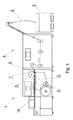
図1はビーズ含ロッド製作用機械1を示す図である。アセテート繊維2を繊維ディスペンサより、通常、ベール3の圧縮アセテート繊維の形で供給する。繊維2はストランド処理ユニット4において、圧縮空気およびシリンダを用いて伸ばし、緩める。結果として、アセテート繊維は広がり、その間により多くの空気を含むことが可能になる。その後、繊維は軟化液(例えば、トリアセチン)で湿らせる。ビーズ含ロッド製作用機械1には漏斗の形をした挿入部材5を設け、これを通して繊維ストランドを運び、ここで繊維の予備圧縮を行う。挿入部材5には通常、開口を設け、繊維の間から余分な空気を容易に排出できるようにする。挿入部材5の背後にアセテート繊維ストランドを誘導する部材6が位置し、ここで予備ストランド変換を行う。部材6は、アセテート繊維ストランドに置くビーズを供給する部材7と共に動作するように構成する。ビーズ配置エリアで動作する供給部材7は、図示していないがビーズ供給装置の一部である。供給部材7は、周囲に複数のビーズ供給ポケットを配列した回転円盤または円筒とすることができる。ビーズ供給部材はまた、直線的に配置したビーズ群を供給する供給部材を設けた供給装置によって位置決めすることも可能であり、該供給部材は例えば楕円軌道の動きをする。一般的に、供給装置には、物体を物体ディスペンサからフィルタ繊維ストランドに物体を配置するエリアまで運ぶように構成した、複数の異なる部材を設けることが可能である。さらに、物体をアセテート繊維ストランドに配置するエリア後方の、ストランドが移動する方向に、粘着性供給ユニット8およびストランドを包んでラッパー9にするユニットが位置する。連続アセテートロッドを個別ロッドに切断する回転切断ヘッド10を機械に設ける。
FIG. 1 is a view showing a bead-containing rod manufacturing machine 1.
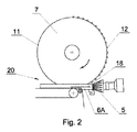
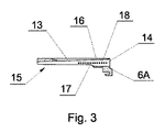
図2は部材6Aを含む機械1の小部分を示す。該部材6Aは繊維ストランドを誘導し、供給ポケット11に複数のビーズ12を設けた円盤の形をした供給部材7と共に動作するように構成する。物体をフィルタ繊維ストランドに配置するエリア20にある供給部材7を、図3に示す部材6Aのスロット13に挿入する。図3は部材6Aの縦断面を示す。フィルタ繊維ストランドを誘導する部材6Aは、入口開口14ならびに出口開口15、および、入口開口14から出口開口15へ伸びる誘導路16を有し、出口開口15はくぼみ17により拡大することが可能である。誘導路は通常円錐形に形成するが、円錐形、円柱形または双曲面状開口の構成のような、異なる形状の経路も可能である。部材6Aには誘導路16に沿って位置する少なくとも1本の通気孔18の列を設ける。通気孔18はスロット13の両側に配置することが可能である。孔18は直線的に、または、不規則に配置することが可能である。
FIG. 2 shows a small part of the machine 1 including the
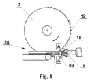
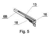
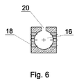
図4は同様の部材6Bを設けた機械1の小部分を示し、該部材6Bはフィルタ繊維ストランドを誘導し、3列の通気孔18を有する。ストランドを誘導する部材6Bの斜視図を図5に示す。図6は、ストランド誘導用部材6Bの、図4でA−Aとマークした位置での横断面を示す。通気孔18はスロット13に対し垂直方向に位置し、スロット13は供給部材7の平面に対し実質的に平行である。図7は、別の実施形態におけるストランド誘導用部材6Bの横断面を示し、ここにおいて、通気孔18は誘導路16に対し放射状に配置してある。
FIG. 4 shows a small part of the machine 1 provided with a
本発明のフィルタ繊維誘導用部材6A、6Bは、供給部材7が垂直面および水平面のどちらで動作する状況でも、つまり、スロットが垂直に、または、水平に位置する状況でも、使用することが可能である。それはまた、他の任意の位置でも使用することが可能である。
The filter
アセテート繊維2の適切に処理したストランドを挿入部材に通し、その後、フィルタ繊維ストランドをストランドに物体を配置するエリア20に誘導する部材6A、6Bの経路16内を移動させる。ストランドを誘導する部材6A、6Bは複数の孔を有し、繊維間にたまった空気を孔18を通して効率的に除去し、排出する。これにより、高い再現性を保ちながら、連続フィルタロッドの軸方向中心に物体を配置することが可能になる。物体配置エリアにおいて空気を効率的な除去することで、物体の、長手方向への配置の再現性は向上する。このエリアにおいて、繊維ストランドは最終的に、特定の直径を有する連続ロッドに変換される。
Properly treated strands of
Claims (8)
変換したフィルタ繊維ストランドを安定させ、物体配置の精度を向上させる通気孔(18)を備えることを特徴とする、部材。 A member (6A, 6B) for guiding the filter fiber strand to an area in the tobacco industry machine (1) where an object is placed on the filter fiber strand, the member supplying the object to the filter fiber strand A slot (13) in which the supply member or object supply device member (7) moves, an inlet opening (14) for filter fiber strands, and an outlet opening (15) for filter fiber strands. And a guide path (16) connecting the inlet opening (14) and the outlet opening (15),
A member comprising a vent (18) that stabilizes the converted filter fiber strands and improves the accuracy of object placement.
請求項1〜5のいずれか一項に記載の部材を備えることを特徴とする、タバコ産業機械。 Filter rod production working tobacco industrial machine containing an object, comprising a processing unit for filter fiber strands, a continuous filter rod conversion unit, an object supply unit, and a unit for cutting continuous rods into individual rods,
A tobacco industry machine comprising the member according to any one of claims 1 to 5.
前記フィルタストランドの繊維間に含まれる余分な空気を通気孔を通じて排出し、フィルタ繊維の前記変換ストランドを安定させ、物体配置の精度を向上させることを特徴とする、方法。 A method for guiding a filter fiber strand to an area in a tobacco industry machine where an object is placed on the filter fiber strand, wherein the filter fiber strand operates with a device for feeding the object to the filter fiber strand. The fiber guide member has a slot through which the supply member or the member of the object supply device moves, wherein the strand is guided in the guide path from the filter fiber inlet opening to the filter fiber strand outlet opening. ,
Excess air contained between the fibers of the filter strands is exhausted through a vent, stabilizing the conversion strands of the filter fibers and improving the accuracy of object placement.
Applications Claiming Priority (3)
| Application Number | Priority Date | Filing Date | Title |
|---|---|---|---|
| PL404795A PL225859B1 (en) | 2013-07-22 | 2013-07-22 | The method and element for conducting the filter fiber band and the machine for producing filter bars |
| PLPL404795 | 2013-07-22 | ||
| PCT/IB2014/063211 WO2015011619A2 (en) | 2013-07-22 | 2014-07-18 | Method and member for guiding a strand of filter fibers and filter rod making machine |
Publications (2)
| Publication Number | Publication Date |
|---|---|
| JP2016524924A true JP2016524924A (en) | 2016-08-22 |
| JP6466441B2 JP6466441B2 (en) | 2019-02-06 |
Family
ID=52393899
Family Applications (1)
| Application Number | Title | Priority Date | Filing Date |
|---|---|---|---|
| JP2016528632A Expired - Fee Related JP6466441B2 (en) | 2013-07-22 | 2014-07-18 | Method and member for guiding filter fiber strand, and filter rod making machine |
Country Status (9)
| Country | Link |
|---|---|
| US (1) | US20160143350A1 (en) |
| EP (1) | EP3024341B1 (en) |
| JP (1) | JP6466441B2 (en) |
| CN (1) | CN105407747B (en) |
| BR (1) | BR112016000625A8 (en) |
| HU (1) | HUE034614T2 (en) |
| PL (1) | PL225859B1 (en) |
| RU (1) | RU2642552C9 (en) |
| WO (1) | WO2015011619A2 (en) |
Families Citing this family (3)
| Publication number | Priority date | Publication date | Assignee | Title |
|---|---|---|---|---|
| PL223115B1 (en) | 2013-02-15 | 2016-10-31 | Int Tobacco Machinery Poland Spółka Z Ograniczoną Odpowiedzialnością | Method and apparatus for temporarily compressing the filtering material |
| US11134713B2 (en) * | 2017-08-04 | 2021-10-05 | Altria Client Services Llc | Method and apparatus for producing micro bead bearing filter rod |
| EP3918929A1 (en) * | 2020-06-03 | 2021-12-08 | International Tobacco Machinery Poland SP. Z O.O. | Method and apparatus for manufacturing of rods |
Citations (3)
| Publication number | Priority date | Publication date | Assignee | Title |
|---|---|---|---|---|
| US3050430A (en) * | 1959-11-12 | 1962-08-21 | Eastman Kodak Co | Jet and method of filter manufacture |
| JPS59227286A (en) * | 1983-06-02 | 1984-12-20 | ア−ル・ジエイ・レノルズ・タバコ・カンパニ− | Tobacco filter, method and apparatus for producing the same |
| JP2010528680A (en) * | 2007-06-11 | 2010-08-26 | アール・ジエイ・レイノルズ・タバコ・カンパニー | Apparatus and associated method for inserting an object into a filter component of a smoking article |
Family Cites Families (28)
| Publication number | Priority date | Publication date | Assignee | Title |
|---|---|---|---|---|
| US3016945A (en) * | 1960-04-25 | 1962-01-16 | Eastman Kodak Co | Method and apparatus for forming tobacco smoke filters |
| US3774508A (en) * | 1968-05-08 | 1973-11-27 | American Filtrona Corp | Apparatus for making filter means |
| US4179323A (en) * | 1973-08-27 | 1979-12-18 | Liggett Group Inc. | Method for making a hollow filter rod |
| US4024012A (en) * | 1973-08-27 | 1977-05-17 | Liggett & Myers Incorporated | Method and apparatus for making a hollow filter and a filter rod |
| US4034765A (en) * | 1975-10-30 | 1977-07-12 | Liggett & Myers Incorporated | Tobacco smoke filter |
| GB2020158B (en) * | 1978-04-21 | 1982-11-24 | Cigarette Components Ltd | Production of tobacco smoke filters |
| US4522616A (en) * | 1982-03-10 | 1985-06-11 | Celanese Corporation | Method and apparatus for forming cigarette filter rods |
| US5203757A (en) * | 1986-11-29 | 1993-04-20 | Rhone Poulenc Rhodia Ag | Method and apparatus for producing tobacco smoke filter rods |
| US4893637A (en) * | 1987-09-15 | 1990-01-16 | R. J. Reynolds Tobacco Co. | Apparatus and methods for making components of a smoking article |
| CN1015865B (en) * | 1988-05-07 | 1992-03-18 | 若迪阿公司 | Method and apparatus for making cigarette filter |
| US5331976A (en) * | 1992-10-21 | 1994-07-26 | Hoechst Celanese Corporation | Transport jet adapter |
| US7074170B2 (en) * | 2002-03-29 | 2006-07-11 | Philip Morris Usa Inc. | Method and apparatus for making cigarette filters with a centrally located flavored element |
| DE102004007841A1 (en) * | 2004-02-17 | 2005-09-08 | Hauni Maschinenbau Ag | Stranding machine, method of operating the same and air conveying system |
| GB2416662A (en) * | 2004-07-30 | 2006-02-08 | C B Kaymich & Company Ltd | Apparatus for applying an additive to cigarette filter tow material |
| CN1265741C (en) * | 2004-08-17 | 2006-07-26 | 常德烟草机械有限责任公司 | Equipment for conveying rod-shaped object in tobacco product |
| WO2007085830A2 (en) * | 2006-01-27 | 2007-08-02 | British American Tobacco (Investments) Limited | Method of preparing a rod for use in the preparation of a smoking article |
| EP3338568A1 (en) * | 2008-11-14 | 2018-06-27 | Philip Morris Products S.A. | Method and apparatus for introducing objects into a smoking article |
| US8303474B2 (en) * | 2009-08-31 | 2012-11-06 | Aiger Group Ag | Apparatus and method for insertion of capsules into filter tows |
| KR20120071390A (en) * | 2009-09-23 | 2012-07-02 | 필트로나 필터 프로덕츠 디벨롭먼트 씨오. 피티이. 엘티디 | Tow cutter |
| US20110162662A1 (en) * | 2010-01-05 | 2011-07-07 | Aiger Group Ag | Apparatus and method for insertion of capsules into filter tows |
| US8622882B2 (en) | 2010-09-27 | 2014-01-07 | Aiger Group Ag | Apparatus and method for insertion of capsules into filter tows |
| US20130102445A1 (en) | 2011-03-25 | 2013-04-25 | Hauni Maschinenbau Ag | High speed object inserter and related methods |
| ITBO20110709A1 (en) * | 2011-12-14 | 2013-06-15 | Gd Spa | COMPACTION UNIT PROVIDED WITH A WIRE INSERTION UNIT FOR AN AUTOMATIC PACKAGING MACHINE FOR THE PRODUCTION OF FILTERS FOR CIGARETTES. |
| CN202396425U (en) * | 2011-12-22 | 2012-08-29 | 新乡东方工业科技有限公司 | Head tightening device for cigarette making machine |
| PL222242B1 (en) * | 2012-01-18 | 2016-07-29 | Int Tobacco Machinery Poland Spółka Z Ograniczoną Odpowiedzialnością | Method and system for the transmission of capsules |
| PL2822409T3 (en) * | 2012-03-05 | 2016-11-30 | Method and device for supplying filter material to a filter rod forming machine | |
| CN202642976U (en) * | 2012-07-03 | 2013-01-02 | 云南玉溪卷烟厂滤嘴棒分厂 | Cut tobacco guiding horn mouth of filter stick forming machine |
| CN202999277U (en) * | 2012-12-19 | 2013-06-19 | 南通烟滤嘴有限责任公司 | Filter rod punching smoke tongue for smoke |
-
2013
- 2013-07-22 PL PL404795A patent/PL225859B1/en unknown
-
2014
- 2014-07-18 EP EP14771374.7A patent/EP3024341B1/en active Active
- 2014-07-18 US US14/903,051 patent/US20160143350A1/en not_active Abandoned
- 2014-07-18 WO PCT/IB2014/063211 patent/WO2015011619A2/en not_active Ceased
- 2014-07-18 CN CN201480041624.6A patent/CN105407747B/en active Active
- 2014-07-18 BR BR112016000625A patent/BR112016000625A8/en not_active IP Right Cessation
- 2014-07-18 RU RU2016104937A patent/RU2642552C9/en active
- 2014-07-18 HU HUE14771374A patent/HUE034614T2/en unknown
- 2014-07-18 JP JP2016528632A patent/JP6466441B2/en not_active Expired - Fee Related
Patent Citations (3)
| Publication number | Priority date | Publication date | Assignee | Title |
|---|---|---|---|---|
| US3050430A (en) * | 1959-11-12 | 1962-08-21 | Eastman Kodak Co | Jet and method of filter manufacture |
| JPS59227286A (en) * | 1983-06-02 | 1984-12-20 | ア−ル・ジエイ・レノルズ・タバコ・カンパニ− | Tobacco filter, method and apparatus for producing the same |
| JP2010528680A (en) * | 2007-06-11 | 2010-08-26 | アール・ジエイ・レイノルズ・タバコ・カンパニー | Apparatus and associated method for inserting an object into a filter component of a smoking article |
Also Published As
| Publication number | Publication date |
|---|---|
| CN105407747B (en) | 2019-08-23 |
| RU2642552C9 (en) | 2018-03-29 |
| BR112016000625A8 (en) | 2021-05-11 |
| US20160143350A1 (en) | 2016-05-26 |
| WO2015011619A3 (en) | 2015-06-25 |
| EP3024341A2 (en) | 2016-06-01 |
| CN105407747A (en) | 2016-03-16 |
| PL404795A1 (en) | 2015-02-02 |
| RU2016104937A (en) | 2017-08-25 |
| EP3024341B1 (en) | 2017-09-13 |
| HUE034614T2 (en) | 2018-02-28 |
| RU2642552C2 (en) | 2018-01-25 |
| PL225859B1 (en) | 2017-05-31 |
| WO2015011619A2 (en) | 2015-01-29 |
| JP6466441B2 (en) | 2019-02-06 |
Similar Documents
| Publication | Publication Date | Title |
|---|---|---|
| EP2893820B1 (en) | Method for producing filter cigarette, filter, and filter cigarette | |
| US20150164133A1 (en) | Filter for a Smoking Article | |
| KR20140143144A (en) | Method and device for supplying filter material to a filter rod forming machine | |
| JP6466441B2 (en) | Method and member for guiding filter fiber strand, and filter rod making machine | |
| CN1882258A (en) | Arrangement for producing filter cigarettes | |
| CN112839534B (en) | Wire band for electronic cigarette mouthpiece, electronic cigarette mouthpiece and their manufacturing methods | |
| CN102573533B (en) | Tow cutter | |
| JPWO2012017850A1 (en) | Filter manufacturing apparatus, filter manufacturing method, and filter | |
| JP2005537814A (en) | Injection of media into the filter segment | |
| JP6824959B2 (en) | How to dry the filter rod | |
| CN107002312A (en) | The manufacture method and tow band manufacture device of tow band | |
| KR102601390B1 (en) | A feeding device for feeding continuous strips within a continuous fiber band in a tobacco industry machine for manufacturing rod-shaped elements and a machine for manufacturing rod-shaped elements | |
| JP2017216914A (en) | Production method of smoking article and smoking article | |
| WO2018091484A1 (en) | A feeding device for feeding a continuous thread into a continuous fibrous band in a tobacco industry machine for manufacturing rod-like elements and a machine for manufacturing rod-like elements | |
| BR112018007389B1 (en) | DEVICE AND METHOD FOR MOVING TUBULAR BODIES | |
| TW201420026A (en) | Method for manufacturing filter cigarette as well as filter and filter cigarette | |
| HK1203322B (en) | Filter for a smoking article |
Legal Events
| Date | Code | Title | Description |
|---|---|---|---|
| A621 | Written request for application examination |
Free format text: JAPANESE INTERMEDIATE CODE: A621 Effective date: 20170526 |
|
| A131 | Notification of reasons for refusal |
Free format text: JAPANESE INTERMEDIATE CODE: A131 Effective date: 20180605 |
|
| A521 | Request for written amendment filed |
Free format text: JAPANESE INTERMEDIATE CODE: A523 Effective date: 20180810 |
|
| A131 | Notification of reasons for refusal |
Free format text: JAPANESE INTERMEDIATE CODE: A131 Effective date: 20181023 |
|
| A521 | Request for written amendment filed |
Free format text: JAPANESE INTERMEDIATE CODE: A523 Effective date: 20181211 |
|
| TRDD | Decision of grant or rejection written | ||
| A01 | Written decision to grant a patent or to grant a registration (utility model) |
Free format text: JAPANESE INTERMEDIATE CODE: A01 Effective date: 20181225 |
|
| A61 | First payment of annual fees (during grant procedure) |
Free format text: JAPANESE INTERMEDIATE CODE: A61 Effective date: 20190109 |
|
| R150 | Certificate of patent or registration of utility model |
Ref document number: 6466441 Country of ref document: JP Free format text: JAPANESE INTERMEDIATE CODE: R150 |
|
| LAPS | Cancellation because of no payment of annual fees |