JP2016513860A - Electrochemical cells containing fibril materials such as fibril cellulose materials - Google Patents
Electrochemical cells containing fibril materials such as fibril cellulose materials Download PDFInfo
- Publication number
- JP2016513860A JP2016513860A JP2015561609A JP2015561609A JP2016513860A JP 2016513860 A JP2016513860 A JP 2016513860A JP 2015561609 A JP2015561609 A JP 2015561609A JP 2015561609 A JP2015561609 A JP 2015561609A JP 2016513860 A JP2016513860 A JP 2016513860A
- Authority
- JP
- Japan
- Prior art keywords
- electrode
- layer
- fibrils
- fibril
- electrolyte
- Prior art date
- Legal status (The legal status is an assumption and is not a legal conclusion. Google has not performed a legal analysis and makes no representation as to the accuracy of the status listed.)
- Pending
Links
Images


Classifications
-
- H—ELECTRICITY
- H01—ELECTRIC ELEMENTS
- H01M—PROCESSES OR MEANS, e.g. BATTERIES, FOR THE DIRECT CONVERSION OF CHEMICAL ENERGY INTO ELECTRICAL ENERGY
- H01M4/00—Electrodes
- H01M4/02—Electrodes composed of, or comprising, active material
- H01M4/62—Selection of inactive substances as ingredients for active masses, e.g. binders, fillers
- H01M4/628—Inhibitors, e.g. gassing inhibitors, corrosion inhibitors
-
- H—ELECTRICITY
- H01—ELECTRIC ELEMENTS
- H01M—PROCESSES OR MEANS, e.g. BATTERIES, FOR THE DIRECT CONVERSION OF CHEMICAL ENERGY INTO ELECTRICAL ENERGY
- H01M10/00—Secondary cells; Manufacture thereof
- H01M10/05—Accumulators with non-aqueous electrolyte
- H01M10/052—Li-accumulators
- H01M10/0525—Rocking-chair batteries, i.e. batteries with lithium insertion or intercalation in both electrodes; Lithium-ion batteries
-
- H—ELECTRICITY
- H01—ELECTRIC ELEMENTS
- H01M—PROCESSES OR MEANS, e.g. BATTERIES, FOR THE DIRECT CONVERSION OF CHEMICAL ENERGY INTO ELECTRICAL ENERGY
- H01M4/00—Electrodes
- H01M4/02—Electrodes composed of, or comprising, active material
- H01M4/06—Electrodes for primary cells
- H01M4/08—Processes of manufacture
-
- H—ELECTRICITY
- H01—ELECTRIC ELEMENTS
- H01M—PROCESSES OR MEANS, e.g. BATTERIES, FOR THE DIRECT CONVERSION OF CHEMICAL ENERGY INTO ELECTRICAL ENERGY
- H01M4/00—Electrodes
- H01M4/02—Electrodes composed of, or comprising, active material
- H01M4/13—Electrodes for accumulators with non-aqueous electrolyte, e.g. for lithium-accumulators; Processes of manufacture thereof
- H01M4/134—Electrodes based on metals, Si or alloys
-
- H—ELECTRICITY
- H01—ELECTRIC ELEMENTS
- H01M—PROCESSES OR MEANS, e.g. BATTERIES, FOR THE DIRECT CONVERSION OF CHEMICAL ENERGY INTO ELECTRICAL ENERGY
- H01M4/00—Electrodes
- H01M4/02—Electrodes composed of, or comprising, active material
- H01M4/13—Electrodes for accumulators with non-aqueous electrolyte, e.g. for lithium-accumulators; Processes of manufacture thereof
- H01M4/139—Processes of manufacture
- H01M4/1395—Processes of manufacture of electrodes based on metals, Si or alloys
-
- H—ELECTRICITY
- H01—ELECTRIC ELEMENTS
- H01M—PROCESSES OR MEANS, e.g. BATTERIES, FOR THE DIRECT CONVERSION OF CHEMICAL ENERGY INTO ELECTRICAL ENERGY
- H01M4/00—Electrodes
- H01M4/02—Electrodes composed of, or comprising, active material
- H01M4/36—Selection of substances as active materials, active masses, active liquids
- H01M4/362—Composites
- H01M4/366—Composites as layered products
-
- H—ELECTRICITY
- H01—ELECTRIC ELEMENTS
- H01M—PROCESSES OR MEANS, e.g. BATTERIES, FOR THE DIRECT CONVERSION OF CHEMICAL ENERGY INTO ELECTRICAL ENERGY
- H01M4/00—Electrodes
- H01M4/02—Electrodes composed of, or comprising, active material
- H01M4/36—Selection of substances as active materials, active masses, active liquids
- H01M4/38—Selection of substances as active materials, active masses, active liquids of elements or alloys
- H01M4/40—Alloys based on alkali metals
- H01M4/405—Alloys based on lithium
-
- H—ELECTRICITY
- H01—ELECTRIC ELEMENTS
- H01M—PROCESSES OR MEANS, e.g. BATTERIES, FOR THE DIRECT CONVERSION OF CHEMICAL ENERGY INTO ELECTRICAL ENERGY
- H01M4/00—Electrodes
- H01M4/02—Electrodes composed of, or comprising, active material
- H01M4/62—Selection of inactive substances as ingredients for active masses, e.g. binders, fillers
- H01M4/621—Binders
- H01M4/622—Binders being polymers
-
- H—ELECTRICITY
- H01—ELECTRIC ELEMENTS
- H01M—PROCESSES OR MEANS, e.g. BATTERIES, FOR THE DIRECT CONVERSION OF CHEMICAL ENERGY INTO ELECTRICAL ENERGY
- H01M50/00—Constructional details or processes of manufacture of the non-active parts of electrochemical cells other than fuel cells, e.g. hybrid cells
- H01M50/40—Separators; Membranes; Diaphragms; Spacing elements inside cells
- H01M50/409—Separators, membranes or diaphragms characterised by the material
- H01M50/411—Organic material
- H01M50/429—Natural polymers
- H01M50/4295—Natural cotton, cellulose or wood
-
- H—ELECTRICITY
- H01—ELECTRIC ELEMENTS
- H01M—PROCESSES OR MEANS, e.g. BATTERIES, FOR THE DIRECT CONVERSION OF CHEMICAL ENERGY INTO ELECTRICAL ENERGY
- H01M50/00—Constructional details or processes of manufacture of the non-active parts of electrochemical cells other than fuel cells, e.g. hybrid cells
- H01M50/40—Separators; Membranes; Diaphragms; Spacing elements inside cells
- H01M50/409—Separators, membranes or diaphragms characterised by the material
- H01M50/44—Fibrous material
-
- H—ELECTRICITY
- H01—ELECTRIC ELEMENTS
- H01M—PROCESSES OR MEANS, e.g. BATTERIES, FOR THE DIRECT CONVERSION OF CHEMICAL ENERGY INTO ELECTRICAL ENERGY
- H01M6/00—Primary cells; Manufacture thereof
- H01M6/14—Cells with non-aqueous electrolyte
-
- H—ELECTRICITY
- H01—ELECTRIC ELEMENTS
- H01M—PROCESSES OR MEANS, e.g. BATTERIES, FOR THE DIRECT CONVERSION OF CHEMICAL ENERGY INTO ELECTRICAL ENERGY
- H01M4/00—Electrodes
- H01M4/02—Electrodes composed of, or comprising, active material
- H01M4/04—Processes of manufacture in general
- H01M4/0402—Methods of deposition of the material
- H01M4/0404—Methods of deposition of the material by coating on electrode collectors
-
- Y—GENERAL TAGGING OF NEW TECHNOLOGICAL DEVELOPMENTS; GENERAL TAGGING OF CROSS-SECTIONAL TECHNOLOGIES SPANNING OVER SEVERAL SECTIONS OF THE IPC; TECHNICAL SUBJECTS COVERED BY FORMER USPC CROSS-REFERENCE ART COLLECTIONS [XRACs] AND DIGESTS
- Y02—TECHNOLOGIES OR APPLICATIONS FOR MITIGATION OR ADAPTATION AGAINST CLIMATE CHANGE
- Y02E—REDUCTION OF GREENHOUSE GAS [GHG] EMISSIONS, RELATED TO ENERGY GENERATION, TRANSMISSION OR DISTRIBUTION
- Y02E60/00—Enabling technologies; Technologies with a potential or indirect contribution to GHG emissions mitigation
- Y02E60/10—Energy storage using batteries
-
- Y—GENERAL TAGGING OF NEW TECHNOLOGICAL DEVELOPMENTS; GENERAL TAGGING OF CROSS-SECTIONAL TECHNOLOGIES SPANNING OVER SEVERAL SECTIONS OF THE IPC; TECHNICAL SUBJECTS COVERED BY FORMER USPC CROSS-REFERENCE ART COLLECTIONS [XRACs] AND DIGESTS
- Y02—TECHNOLOGIES OR APPLICATIONS FOR MITIGATION OR ADAPTATION AGAINST CLIMATE CHANGE
- Y02P—CLIMATE CHANGE MITIGATION TECHNOLOGIES IN THE PRODUCTION OR PROCESSING OF GOODS
- Y02P70/00—Climate change mitigation technologies in the production process for final industrial or consumer products
- Y02P70/50—Manufacturing or production processes characterised by the final manufactured product
Abstract
電気化学電池およびその要素におけるフィブリルセルロース材料および他の類似材料などのフィブリル材料の使用が概して記載される。The use of fibril materials such as fibril cellulose materials and other similar materials in electrochemical cells and elements thereof is generally described.
Description
(関連出願)
本願は、米国特許法第119条(e)に基づき、発明の名称「Electrochemical Cells Comprising Fibril Materials,Such as Fibril Cellulose Materials」の、2013年3月5日に出願した米国仮特許出願第61/772,627号に対して優先権を主張し、全ての目的のためにその全体が参照により本明細書中に組み込まれる。
(Related application)
This application is based on US Patent No. 119 (e), and is based on US Provisional Patent Application No. 61/772 filed on Mar. 5, 2013, entitled "Electrochemical Cells Compiling Fibrial Materials, Such as Fibrous Materials". , 627, which is hereby incorporated by reference in its entirety for all purposes.
電気化学電池およびその要素におけるフィブリルセルロース材料および他の類似材料などのフィブリル材料の使用が概して記載される。 The use of fibril materials such as fibril cellulose materials and other similar materials in electrochemical cells and elements thereof is generally described.
電気化学電池には、主に電気化学反応に関与して電流を発生する正極および負極が含まれる。一般的に、電気化学反応は、遊離イオンを含有することができ、かつイオン伝導性媒体として作用することができる電解質によって促進される。 The electrochemical cell mainly includes a positive electrode and a negative electrode that generate current by being involved in an electrochemical reaction. In general, the electrochemical reaction is facilitated by an electrolyte that can contain free ions and can act as an ion-conducting medium.
電気化学電池の性能は、上記電池内の電気化学反応速度を増大させることができる電極活性物質および電解質の間の接触量を増加することによって向上することができる。更に、電気化学電池の性能は、電極の体積内での高い電気伝導度を維持することによって、向上することができる。いくつかのこれまでの電気化学電池において、多孔性炭素粒子の凝集体などの支持構造体の上または中に配置された電極活性物質を含む多孔性電極を使用することによって、これらの目的をある程度達成することができる。 The performance of the electrochemical cell can be improved by increasing the amount of contact between the electrode active material and the electrolyte that can increase the electrochemical reaction rate within the cell. Furthermore, the performance of the electrochemical cell can be improved by maintaining high electrical conductivity within the volume of the electrode. In some previous electrochemical cells, these objectives are achieved to some extent by using a porous electrode comprising an electrode active material disposed on or in a support structure such as an aggregate of porous carbon particles. Can be achieved.
リチウムを電極活性物質として用いる電気化学電池などの電気化学電池の性能は、電気化学電池に異方性の力を加えることによって更に向上することができる。 The performance of an electrochemical cell such as an electrochemical cell using lithium as an electrode active material can be further improved by applying an anisotropic force to the electrochemical cell.
電気化学電池およびその要素におけるフィブリルセルロースおよび類似の材料などのフィブリル材料の使用が概して記載される。いくらかの態様においては、上記フィブリル材料は、電気化学電池および電気化学電池の要素を機械的に強化するのに役立つことができる。本発明の要件には、場合によっては、相関的製品、特定の課題に対する代替案、および/または、1つ以上のシステムおよび/または物品の複数の異なる使用を含む。 The use of fibril materials such as fibril cellulose and similar materials in electrochemical cells and components thereof is generally described. In some embodiments, the fibril material can serve to mechanically strengthen electrochemical cells and elements of electrochemical cells. The requirements of the present invention include, in some cases, correlated products, alternatives to specific issues, and / or multiple different uses of one or more systems and / or articles.
1つの態様において、電極が提供される。いくつかの態様において、電極は、電気化学活性物質並びに、電気化学活性物質および/または電気化学活性物質を支持する支持材料の少なくとも一部と接触した電子非伝導性フィブリルおよび/または高分子フィブリルを含む。いくつかの態様において、上記フィブリルの少なくとも一部は、約1μm未満の最大断面直径および少なくとも約10:1のアスペクト比を有する。 In one aspect, an electrode is provided. In some embodiments, the electrode comprises an electrochemically active material and an electronically non-conductive fibril and / or a polymeric fibril in contact with the electrochemically active material and / or at least a portion of a support material that supports the electrochemically active material. Including. In some embodiments, at least some of the fibrils have a maximum cross-sectional diameter of less than about 1 μm and an aspect ratio of at least about 10: 1.
いくつかの態様において、電極は、電気化学活性物質、上記電気化学活性物質上の保護層、並びに上記保護層内および/または上記保護層上のフィブリル含有層内のフィブリル材料を含む。いくつかの態様において、上記フィブリルの少なくとも一部が、電子非伝導性および/または高分子であり、かつ上記フィブリルの少なくとも一部が、約1μm未満の最大断面直径および少なくとも約10:1のアスペクト比を有する。 In some embodiments, the electrode includes an electrochemically active material, a protective layer on the electrochemically active material, and a fibril material in the protective layer and / or in a fibril-containing layer on the protective layer. In some embodiments, at least some of the fibrils are electronically non-conductive and / or macromolecules, and at least some of the fibrils have a maximum cross-sectional diameter of less than about 1 μm and an aspect of at least about 10: 1. Have a ratio.
いくらかの態様において、電気化学電池を提供する。いくらかの態様において、電気化学電池は、負極、正極、および上記負極および正極と電気化学的に連通する電解質を含み、上記電解質が、約1μm未満の最大断面直径および少なくとも約10:1のアスペクト比を有するセルロースまたはセルロース誘導体を含む複数のフィブリルを含む。 In some embodiments, an electrochemical cell is provided. In some embodiments, the electrochemical cell includes a negative electrode, a positive electrode, and an electrolyte in electrochemical communication with the negative electrode and the positive electrode, wherein the electrolyte has a maximum cross-sectional diameter of less than about 1 μm and an aspect ratio of at least about 10: 1. A plurality of fibrils comprising cellulose or cellulose derivatives having
いくつかの態様において、電気化学電池は、負極、正極、並びに上記負極および正極と電気化学的に連通する電解質を含み、上記電解質が、約10nm未満の最大断面直径および少なくとも約10:1のアスペクト比を有する複数の高分子フィブリルおよび/または電子非伝導性フィブリルを含む。 In some embodiments, the electrochemical cell includes a negative electrode, a positive electrode, and an electrolyte in electrochemical communication with the negative electrode and the positive electrode, wherein the electrolyte has a maximum cross-sectional diameter of less than about 10 nm and an aspect of at least about 10: 1. A plurality of polymeric fibrils and / or electronic non-conductive fibrils having a ratio.
いくつかの態様において、電気化学電池は、負極、正極、並びに上記負極および正極と電気化学的に連通する電解質を含み、上記負極、正極および電解質の少なくとも1つが、セルロースまたはセルロース誘導体を含むフィブリル材料を含む。 In some embodiments, an electrochemical cell includes a negative electrode, a positive electrode, and an electrolyte in electrochemical communication with the negative electrode and the positive electrode, wherein at least one of the negative electrode, the positive electrode, and the electrolyte includes cellulose or a cellulose derivative. including.
1つの態様において、方法が提供される。いくらかの態様において、上記方法は、液体キャリア中に懸濁された微粒子支持材料およびフィブリルを含む懸濁液を調製する工程、基材の少なくとも一部を上記懸濁液で被覆する工程、および上記液体キャリアの少なくとも一部を上記懸濁液から除去する工程を含む。いくつかの態様において、上記フィブリルの少なくとも一部が電子非伝導性および/または高分子であり、かつ上記フィブリルの少なくとも一部が約1μm未満の最大断面直径および少なくとも約10:1のアスペクト比を有する。 In one aspect, a method is provided. In some embodiments, the method comprises preparing a suspension comprising particulate support material and fibrils suspended in a liquid carrier, coating at least a portion of a substrate with the suspension, and Removing at least a portion of the liquid carrier from the suspension. In some embodiments, at least some of the fibrils are electronically non-conductive and / or polymeric, and at least some of the fibrils have a maximum cross-sectional diameter of less than about 1 μm and an aspect ratio of at least about 10: 1. Have.
1組の態様において、上記方法は、電気化学活性物質の層および上記電気化学活性物質の層の上の保護層を含む電極を提供する工程、並びにフィブリル含有層を上記保護層に隣接して配置する工程を含む。 In one set of embodiments, the method includes providing an electrode including a layer of electrochemically active material and a protective layer over the layer of electrochemically active material, and placing a fibril-containing layer adjacent to the protective layer. Including the step of:
本発明の他の優位性および新規な特徴が、添付の図面と併せて考慮する場合に、以下の発明の様々な非限定的態様の詳細な説明から明らかとなる。本明細書および参照により組み込まれた文献が、対立するおよび/または矛盾する開示を含む場合、本明細書中により統制すべきである。 Other advantages and novel features of the invention will become apparent from the following detailed description of various non-limiting aspects of the invention when considered in conjunction with the accompanying drawings. In cases where the present specification and a document incorporated by reference include conflicting and / or conflicting disclosures, the present specification should control.
概略図であり、正確な縮尺率ではない添付の図面を参照して、本発明の非限定的態様を例示として説明する。上記図において、説明されたそれぞれの同一またはほぼ同一の要素は、多くの場合、1つの数字によって表される。明確にするため、すべての構成要素がすべての図に分類されているとは限らず、また、当業者が本発明を理解できるようにするのに説明が必要でない本発明の各態様のすべての構成要素であるとは限らない。
電気化学電池および電気化学電池の要素におけるフィブリルセルロースおよび類似の材料などのフィブリル材料の使用が概して記載される。上記フィブリル材料は、いくつかの態様において、電気化学電池の1つ以上の要素の機械的強化を提供する。いくらかの態様において、電気化学電池の様々な部分における、そのようなフィブリル材料の使用により、電気化学電池に構造的に損傷を与えたり、構造的に支障を来したりすることなく、電気化学電池に異方性の力を加えることを可能とすることができる。フィブリル材料は、電気化学電池内の電極、セパレータ、および/または電解質材料(例えば、ゲル電解質材料および/または固体電解質材料)に組み込むことができる。いくつかの態様において、フィブリル材料は、電気化学電池の要素に構造的支持を提供するのに用いられる結合剤に取って代わったり、上記結合剤を補ったりすることができる。 The use of fibril materials such as fibril cellulose and similar materials in electrochemical cells and electrochemical cell elements is generally described. The fibril material provides, in some embodiments, mechanical reinforcement of one or more elements of the electrochemical cell. In some embodiments, the use of such fibril materials in various parts of the electrochemical cell allows the electrochemical cell to be structurally damaged without causing structural damage to the electrochemical cell. It is possible to apply an anisotropic force to. Fibril materials can be incorporated into electrodes, separators, and / or electrolyte materials (eg, gel electrolyte materials and / or solid electrolyte materials) in electrochemical cells. In some embodiments, the fibril material can replace or supplement the binder used to provide structural support to the elements of the electrochemical cell.
本明細書中に記載されたいくらかの態様は、使用時に電気化学電池に異方性の力が加えられる電気化学電池に特に有用である。発明の名称「Application of Force in Electrochemical Cells」の、2009年8月4日出願の、Scordilis−Kelleyらの米国特許出願公開第2010/0035128号明細書(全ての目的のためにその全体が参照により本明細書中に組み込まれる)には、向上した電極の化学的性質、微細構造、および/または向上した電池特性を示す他の特性のために、力を加えることが記載されている。いくつかの電気化学電池(例えば、再充電性電気化学電池)は、充電および電極表面上の金属の反応時の電極(例えば、負極)表面上での金属(例えば、リチウム金属または他の活性物質)の析出を含む充電/放電サイクルを受け、上記金属は放電時に負極表面から拡散する。そのような電池において金属が析出する均一性は、電池性能に悪影響を与える可能性がある。1つの非限定的な例として、リチウム金属が負極から除去および/または負極に再析出されると、場合によっては、平滑でない表面を生じる可能性があり;例えば再析出時に、リチウムは平滑でなく析出して粗い表面を形成する。粗化された表面により、サイクル寿命を短くし、および/または電池性能を低下する望ましくない化学反応のために得られるリチウム金属量を増加する可能性がある。電気化学電池内の電極活性表面に垂直な要素に対して異方性の力を加えることによって、そのような挙動が低減され、サイクル寿命および/または電池性能が向上することがわかった。 Some aspects described herein are particularly useful for electrochemical cells where an anisotropic force is applied to the electrochemical cell in use. No. 2010/0035128 of Scordilis-Kelley et al., Filed Aug. 4, 2009, entitled “Application of Force in Electrochemical Cells” (incorporated in its entirety for all purposes by reference). (Incorporated herein) describes applying force due to improved electrode chemistry, microstructure, and / or other properties that exhibit improved battery properties. Some electrochemical cells (eg, rechargeable electrochemical cells) are metals (eg, lithium metal or other active materials) on the electrode (eg, negative electrode) surface during charging and reaction of the metal on the electrode surface. And the metal diffuses from the negative electrode surface during discharge. The uniformity of metal deposition in such batteries can adversely affect battery performance. As one non-limiting example, removal of lithium metal from the negative electrode and / or reprecipitation onto the negative electrode can result in a non-smooth surface; for example, during re-deposition, lithium is not smooth. Precipitate to form a rough surface. A roughened surface can reduce cycle life and / or increase the amount of lithium metal obtained due to undesirable chemical reactions that degrade battery performance. It has been found that applying anisotropic forces to elements perpendicular to the electrode active surface in an electrochemical cell reduces such behavior and improves cycle life and / or cell performance.
しかしながら、比較的脆弱な電極および/または電解質、電解質セパレータ、或いは比較的容易に破壊、引き裂きまたは支障を来たす他の要素を含む電気化学電池に異方性の力を加えると、電池性能が悪影響を与えられる。1つの非限定的な例として、電気化学電池が、比較的容易に変形し、および/または比較的容易に曲がることができる材料(例えば、電極内の多孔性粒子を共に保持するのに用いられるいくらかの結合剤)を用いて共に保持される要素を有する電極を含む場合、異方性の力を加えることによって、電極の気孔率を低減することができ(例えば、上記電極内で、電極材料を圧縮する、または接着材料を提供することによって)、従って電池性能を低下させる。別の非限定的な例として、電気化学電池が、電解質および/または曲がり、破裂し、または容易に変形する電解質セパレータを含む場合、異方性の力を加えることによって、電気化学電池内に短絡を生じさせることができる。従って、電気化学電池に構造的安定性を付与する材料を組み込むことは、多くの場合、非常に重要であることができる。 However, applying anisotropic forces to relatively fragile electrodes and / or electrolytes, electrolyte separators, or other elements that are relatively easy to break, tear or interfere with cell performance can adversely affect cell performance. Given. As one non-limiting example, an electrochemical cell is used to hold together porous materials within an electrode that can be relatively easily deformed and / or bend relatively easily. When including an electrode having elements held together with some binder), the porosity of the electrode can be reduced by applying an anisotropic force (eg, within the electrode, the electrode material , Or providing an adhesive material), thus reducing battery performance. As another non-limiting example, if the electrochemical cell includes an electrolyte and / or an electrolyte separator that bends, ruptures, or easily deforms, a short circuit within the electrochemical cell by applying an anisotropic force Can be generated. Thus, incorporating materials that impart structural stability to electrochemical cells can often be very important.
いくらかの態様において、本明細書中に記載された上記フィブリル材料は、たとえ少量のフィブリル材料を用いても、大きな程度の構造的強化を提供する。電気化学電池において用いられる強化材料量を低減する能力は、上記電池の電気化学活性要素に対する、上記強化材料によって占有される上記電池内の総体積を低減することによって、比較的高いエネルギー密度および比エネルギーを有する電池を製造することを可能とする。 In some embodiments, the fibril material described herein provides a great degree of structural reinforcement, even with small amounts of fibril material. The ability to reduce the amount of reinforcing material used in an electrochemical cell is a relatively high energy density and ratio by reducing the total volume in the cell occupied by the reinforcing material relative to the electrochemically active element of the cell. It makes it possible to produce a battery with energy.
いくらかの態様において、フィブリルは電子非伝導性であってもよい。例えば、いくらかの態様において、フィブリルは、少なくとも約106Ω・m、少なくとも約108Ω・m、少なくとも約1010Ω・m、少なくとも約1012Ω・m、または少なくとも約1014Ω・mの20℃でのバルク電気抵抗率を有する。 In some embodiments, the fibrils may be electronically non-conductive. For example, in some embodiments, the fibrils are at least about 10 6 Ω · m, at least about 10 8 Ω · m, at least about 10 10 Ω · m, at least about 10 12 Ω · m, or at least about 10 14 Ω · m. The bulk electrical resistivity at 20 ° C.
いくつかの態様において、フィブリルは高分子であってもよい。上記フィブリルの全てまたは一部は、いくつかの態様において、天然高分子から形成されてもよい。いくつかの態様において、上記フィブリルは多糖類を含む。例えば、いくつかの態様において、上記フィブリルはグルコースを含んでもよい。いくつかの態様において、上記フィブリルは、セルロースまたはセルロース誘導体を含む。上記セルロース誘導体は、アルキル、アリール、ヘテロアルキル、ヘテロアリール、ヘテロ環、カルボニル、ハロ、ヒドロキシル、ニトロ、スルホ、シアノ、アルコール基、それらの混合物などを含む、1種以上の官能基で置換したセルロース系高分子を含んでもよい。いくつかの態様において、上記セルロース誘導体は、カルボキシアルキルセルロースである。好適なセルロース誘導体の例には、それらに限定されないが、カルボキシメチルセルロース(CMC)、メチルカルボキシメチルセルロース(MCMC)、ヒドロキシエチルカルボキシメチルセルロース(HECMC)、ヒドロキシエチルメチルカルボキシメチルセルロース(HEMCMC)、スルホエチルカルボキシメチルセルロース(SECMC)、ヒドロキシエチルヒドロキシプロピルセルロース(HEHPC)、ヒドロキシエチルエチルセルロース(HEEC)、ヒドロキシエチルスルホエチルセルロース(HESEC)、ヒドロキシプロピルメチルセルロース(HPMC)、ヒドロキシエチルセルロース(HEC)、ヒドロキシプロピルセルロース(HPC)、ヒドロキシエチルメチルセルロース(HEMC)、ヒドロキシエチルメチルセルロース(HEMC)、メチルセルロース(MC)、またはそれらの混合物が挙げられる。当業者は、セルロースフィブリル材料を含むフィブリル材料を製造する技術に精通している。例えば、多糖類(例えば、セルロースおよび/またはそれらの誘導体)を含有するフィブリル材料は、多糖類のフィブリルを含有する植物から得ることができる。例えば、植物内のセルロース繊維を(例えば、酸加水分解を用いて)分解して、セルロースフィブリルを製造することができる。フィブリルセルロースの大量生産は、例えばUPM(フィンランドのヘルシンキ)およびInnventia(スウェーデンのストックホルム)によって着手された。 In some embodiments, the fibrils may be macromolecules. All or part of the fibrils may be formed from natural polymers in some embodiments. In some embodiments, the fibril comprises a polysaccharide. For example, in some embodiments, the fibrils may include glucose. In some embodiments, the fibril comprises cellulose or a cellulose derivative. The cellulose derivative is a cellulose substituted with one or more functional groups including alkyl, aryl, heteroalkyl, heteroaryl, heterocycle, carbonyl, halo, hydroxyl, nitro, sulfo, cyano, alcohol groups, mixtures thereof, etc. System polymer may be included. In some embodiments, the cellulose derivative is carboxyalkyl cellulose. Examples of suitable cellulose derivatives include, but are not limited to, carboxymethyl cellulose (CMC), methyl carboxymethyl cellulose (MCMC), hydroxyethyl carboxymethyl cellulose (HECMC), hydroxyethyl methyl carboxymethyl cellulose (HEMCMC), sulfoethyl carboxymethyl cellulose ( SECMC), hydroxyethylhydroxypropylcellulose (HEHPC), hydroxyethylethylcellulose (HEEC), hydroxyethylsulfoethylcellulose (HESEC), hydroxypropylmethylcellulose (HPMC), hydroxyethylcellulose (HEC), hydroxypropylcellulose (HPC), hydroxyethylmethylcellulose (HEMC), hydroxyethyl Chill cellulose (HEMC), methylcellulose (MC), or mixtures thereof. Those skilled in the art are familiar with techniques for producing fibril materials, including cellulose fibril materials. For example, fibrillar materials containing polysaccharides (eg, cellulose and / or derivatives thereof) can be obtained from plants containing polysaccharide fibrils. For example, cellulose fibers in plants can be degraded (eg, using acid hydrolysis) to produce cellulose fibrils. Mass production of fibril cellulose has been undertaken, for example, by UPM (Helsinki, Finland) and Inventia (Stockholm, Sweden).
いくらかの態様において、上記フィブリルは比較的小さな最大断面直径を有してもよい。いくつかの態様において、上記フィブリルの少なくとも一部は、約1μm未満、約100nm未満、約10nm未満、約1nm未満(および/または、いくらかの態様において、0.01nmまで、またはそれ未満)の最大断面直径を有する。いくつかの態様において、少なくとも約10%、少なくとも約25%、少なくとも約50%、少なくとも約75%、少なくとも約90%、または少なくとも約95%のフィブリル材料によって占有される総体積は、約1μm未満、約100nm未満、約10nm未満、約1nm未満(および/または、いくらかの態様において、0.01nmまで、またはそれ未満)の最大断面直径を有するフィブリルから構成される。 In some embodiments, the fibrils may have a relatively small maximum cross-sectional diameter. In some embodiments, at least some of the fibrils have a maximum of less than about 1 μm, less than about 100 nm, less than about 10 nm, less than about 1 nm (and in some embodiments, up to or less than 0.01 nm). Having a cross-sectional diameter. In some embodiments, the total volume occupied by at least about 10%, at least about 25%, at least about 50%, at least about 75%, at least about 90%, or at least about 95% fibril material is less than about 1 μm , Having a maximum cross-sectional diameter of less than about 100 nm, less than about 10 nm, less than about 1 nm (and / or in some embodiments, up to or less than 0.01 nm).
いくらかの態様において、上記フィブリルは細長くてもよい。例えば、いくつかの態様において、上記フィブリルは少なくとも約10:1、少なくとも約100:1、少なくとも約1000:1(および/または、いくらかの態様において、約10,000:1以下、またはそれより大きい)のアスペクト比を有する。いくつかの態様において、いくつかの態様において、少なくとも約10%、少なくとも約25%、少なくとも約50%、少なくとも約75%、少なくとも約90%、または少なくとも約95%のフィブリル材料によって占有される総体積は、少なくとも約10:1、少なくとも約100:1、少なくとも約1000:1(および/または、いくらかの態様において、約10,000:1以下、またはそれより大きい)のアスペクト比を有するフィブリルから構成される。 In some embodiments, the fibrils may be elongated. For example, in some embodiments, the fibrils are at least about 10: 1, at least about 100: 1, at least about 1000: 1 (and / or in some embodiments about 10,000: 1 or less, or greater). ) Aspect ratio. In some embodiments, in some embodiments, the total occupied by at least about 10%, at least about 25%, at least about 50%, at least about 75%, at least about 90%, or at least about 95% fibril material. The volume is from fibrils having an aspect ratio of at least about 10: 1, at least about 100: 1, at least about 1000: 1 (and / or in some embodiments, about 10,000: 1 or less, or greater). Composed.
いくらかの態様は、フィブリル材料を含む電気化学電池に関する。いくらかの態様において、上記電気化学電池の少なくとも1つの要素は、例えば、上記電気化学電池の要素を構造的に強化するのに用いることができるフィブリル材料を含む。「電気化学電池」の語は、一次および二次電気化学電池を包含する。従って、本明細書中に記載された本発明の電気化学電池の配置および材料は、何度も充電および放電され得る、一次および/または二次電池(一次および二次バッテリーを含む)に用いることができる。いくつかの態様において、本明細書中に記載された材料、系および方法を、リチウム系電気化学電池およびそれらのバッテリーに関連して用いることができる。いくらかの態様において、本明細書中に記載された多孔性支持構造体および/または電極を、リチウム‐硫黄バッテリーに用いることができる。 Some embodiments relate to an electrochemical cell comprising a fibril material. In some embodiments, the at least one element of the electrochemical cell includes a fibril material that can be used, for example, to structurally strengthen the element of the electrochemical cell. The term “electrochemical cell” includes primary and secondary electrochemical cells. Thus, the electrochemical cell arrangements and materials described herein are used for primary and / or secondary batteries (including primary and secondary batteries) that can be charged and discharged many times. Can do. In some embodiments, the materials, systems and methods described herein can be used in connection with lithium-based electrochemical cells and their batteries. In some embodiments, the porous support structures and / or electrodes described herein can be used in lithium-sulfur batteries.
本発明によれば、幅広い種類の電気化学デバイスにおける用途を見出すことができるが、1つのそのようなデバイスの例を例示のためだけの図1に示す。図1は、正極110および負極112を含む電気化学電池100の概略図である。更に、上記電気化学電池は電解質114を含む。上記電解質は、正極および負極と電気化学的に連通する1つ以上の要素を含むことができる。図1に示す正極、負極および電解質は平面構造を有するように示されているが、他の態様において非平面構造(例えば、円柱形、S字形)を含んでもよい。図1において、電気化学電池100はまた収納構造体116を含む。
Although the present invention can find application in a wide variety of electrochemical devices, an example of one such device is shown in FIG. 1 for illustration only. FIG. 1 is a schematic diagram of an
もちろん、要素の幾何学的配置は変わることができ、層の配置が変わった他の態様が存在すると解されるべきである。更に、非平面配置、示されたものと異なる材料の比を有する配置、および他の配置が、本発明に関して有用である。典型的な電気化学電池はまた、もちろん、集電体、外部回路などを含む。当業者は、図に示され、かつ本明細書中に記載されるような一般的概略配置と共に用いることができる多数の配置を十分認識している。 Of course, it should be understood that the geometrical arrangement of the elements can vary and that there are other ways in which the arrangement of the layers has changed. Furthermore, non-planar arrangements, arrangements having a ratio of materials different from those shown, and other arrangements are useful with the present invention. A typical electrochemical cell will of course also include a current collector, an external circuit, and the like. Those skilled in the art are well aware of the numerous arrangements that can be used with the general schematic arrangements shown in the figures and described herein.
いくらかの態様は、例えば、電極を機械的に強化するために、フィブリル材料が組み込まれた電極に関する。そのような電極を、電気化学電池(例えば、前述のような)および/または電極を使用する他のデバイスに用いることができる。フィブリル材料を含む電極は、以下に更に詳細に記載されるように、負極および/または正極として用いることができる。上記フィブリル材料は、上記電池内の電気化学活性物質および/または電気化学的に活性でない材料(例えば、結合剤、電極(例えば、多孔性またはそうでない、金属粒子、カーボン粒子など)に電子伝導性を付与する材料)および/または上記電池内の他の材料と接触および/またはそれによって少なくとも部分的に取り囲まれてもよい。 Some embodiments relate to an electrode incorporating a fibril material, for example, to mechanically strengthen the electrode. Such electrodes can be used in electrochemical cells (eg, as described above) and / or other devices that use electrodes. The electrode comprising the fibril material can be used as a negative electrode and / or a positive electrode, as described in more detail below. The fibril material is electronically conductive to the electrochemically active material and / or non-electrochemically active material (eg, binders, electrodes (eg, porous or otherwise, metal particles, carbon particles, etc.) within the battery. Material) and / or other materials in the battery and / or thereby at least partially surrounded.
いくつかの態様において、フィブリル材料を多孔性電極に組み込むことができる。例えば、いくらかの態様において、上記電極は、支持材料および支持材料と混合された電気化学活性物質を含む。上記支持材料は、いくらかの態様において、上記電気化学活性物質を支持することができる。いくらかのそのような態様において、フィブリルは、上記電気化学活性物質および/または上記支持材料の少なくとも一部と接触および/またはそれらによって少なくとも部分的に取り囲まれてもよい。 In some embodiments, fibril material can be incorporated into the porous electrode. For example, in some embodiments, the electrode includes a support material and an electrochemically active material mixed with the support material. The support material can support the electrochemically active material in some embodiments. In some such embodiments, fibrils may be in contact with and / or at least partially surrounded by at least a portion of the electrochemically active material and / or the support material.
いくつかの態様において、上記電極は、上記電気化学活性物質、上記フィブリルおよび1つ以上の支持材料(例えば、(電気伝導性であってもよい)複数の粒子および/または結合剤)を含むマトリックスを含む。図2は、いくらかの態様による1つのそのような電極200の断面概略図である。図2において、電極200は支持材料202を含む。上記支持材料は、支持材料202を形成する粒子204などの複数の粒子を含むことができる。粒子204は、以下に詳細に記載されるように、カーボン、金属、およびセラミック材料を含む様々な好適な材料から形成されてもよい。電極200はまた、電気化学活性物質206を含んでもよい。上記電気化学活性物質は、上記粒子間に形成された細孔(即ち、粒子間細孔)内、粒子内に形成された細孔(即ち、粒子内細孔)内、またはそれらの両方に配置されてもよい。いくらかの態様において、電極200はまた、明確にするために図2には表示していない結合剤を含む。
In some embodiments, the electrode comprises a matrix comprising the electrochemically active material, the fibril, and one or more support materials (eg, a plurality of particles (and may be electrically conductive) and / or a binder). including. FIG. 2 is a cross-sectional schematic view of one
電極200は更に、電気化学活性物質206および/または支持材料202の少なくとも一部と接触する複数のフィブリル208を含んでもよい。いくらかの態様において、上記フィブリルは、支持材料粒子(例えば、電子伝導性支持材料粒子)の少なくとも一部を互いと機械的に接合する。例えば、図2において、フィブリル208Aは、支持材料粒子を互いと機械的に接合する。いくつかの態様において、上記フィブリルは、電子伝導性粒子の少なくとも一部を電極活性物質に接合する。例えば、図2において、フィブリル208Bは、支持材料粒子を電気化学活性物質に機械的に接合する。上記フィブリルはまた、支持材料内に存在する。例えば、フィブリルは、結合剤または電極内の他の支持材料によって少なくとも部分的に取り囲まれてもよい。いくつかの態様において、上記フィブリルの存在により、支持材料粒子を機械的に強化し、例えば、結合剤などの支持材料の変形および/または降伏に対する耐性を提供する。
The
フィブリル材料を含む多孔性電極は、好適な方法を用いることによって作製することができる。いくらかの態様において、上記電極は、液体キャリア中に懸濁した上記フィブリル材料および支持材料を含む懸濁液を調製することによって製造される。上記懸濁液は、次いで、集電体などの基材の少なくとも一部を被覆するのに用いることができる。上記懸濁液を被覆した後、上記液体キャリアの少なくとも一部を除去することができる。 A porous electrode containing a fibril material can be produced by using a suitable method. In some embodiments, the electrode is manufactured by preparing a suspension comprising the fibril material and a support material suspended in a liquid carrier. The suspension can then be used to coat at least a portion of a substrate such as a current collector. After coating the suspension, at least a portion of the liquid carrier can be removed.
いくらかの態様において、電極活性物質を、支持材料および/またはフィブリルと混合することができる。いくつかの態様において、上記電極活性物質を、上記懸濁液を被覆する前に、上記支持材料およびフィブリルと混合することができる(例えば、上記電極活性物質が、上記懸濁液の成分となり得る)。いくつかの態様において、上記電極活性物質を、上記液体キャリアの少なくとも一部を除去するために上記懸濁液を乾燥する前に上記支持材料およびフィブリルと混合することができる。いくつかの態様において、上記電極活性物質を、少なくとも一部(後に実質的に全て)または液体キャリアを除去した後、上記支持材料およびフィブリルと混合することができる。 In some embodiments, the electrode active material can be mixed with a support material and / or fibrils. In some embodiments, the electrode active material can be mixed with the support material and fibrils prior to coating the suspension (eg, the electrode active material can be a component of the suspension). ). In some embodiments, the electrode active material can be mixed with the support material and fibrils prior to drying the suspension to remove at least a portion of the liquid carrier. In some embodiments, the electrode active material can be mixed with the support material and fibrils after removing at least a portion (substantially all later) or liquid carrier.
上記支持材料は、例えば、図2の微粒子材料204などの微粒子材料を含む。いくらかの態様において、上記支持材料の粒子は、約5mm未満、約1mm未満、または約500μm未満の最大断面直径を有してもよい。上記微粒子材料は、多孔性であっても、または非多孔性であってもよく、それらに限定されないが、炭素、1つ以上の金属、1つ以上のセラミックなどを含む様々な材料から形成されてもよい。
The support material includes, for example, a particulate material such as the
いくらかの態様において、上記支持材料は結合剤を含む。「結合剤材料」により、電極内に存在する場合、上記電極の要素の接着性および粘着性を強化する材料を意味する。好適な結合剤材料は、それらに限定されないが、正極、負極および電解質を含む上記電池の他の要素と適合性を有する(例えば、上記他の要素に対して不活性である)ように選択されてもよい。例えば、電気化学電池はポリスルフィドを含んでもよく、かつ上記結合剤材料は、動作時に上記電池内でポリスルフィドと反応する可能性があり、かつ実質的に不可逆的に生成された副生成物で上記電池を汚染する可能性がある、カルボニル基(例えば、エステル、ケトン、アルデヒドなど)などの特定の官能基を含有しないように選択されてもよい。上記結合剤材料はまた、上記支持材料(例えば、多孔性カーボン材料)に対して良好な接着力を示すように、および/または加工時または電池動作時に亀裂や層間剥離を起こさないように選択されてもよい。いくつかの態様において、上記結合剤材料は、電解質に対して実質的に不溶性であるように、即ち、上記結合剤材料は、電解質によって溶解しないように、および/または液体キャリアに対してかなり可溶性であるように選択されてもよい。上記結合剤材料は、上記結合剤材料が実質的に溶媒中で可溶性であるように提供されてもよい。場合によっては、上記結合剤材料は、非水性液体キャリアに実質的に可溶性であってもよい。場合によっては、上記結合剤材料は、水性液体キャリアに実質的に可溶性であってもよい。 In some embodiments, the support material includes a binder. By “binder material” is meant a material that, when present in an electrode, enhances the adhesion and tackiness of the electrode elements. Suitable binder materials are selected to be compatible (eg, inert to the other elements) with other elements of the battery including, but not limited to, positive electrodes, negative electrodes, and electrolytes. May be. For example, an electrochemical cell may include a polysulfide, and the binder material may react with the polysulfide in the cell during operation and the by-product generated substantially irreversibly. May be selected so as not to contain certain functional groups such as carbonyl groups (eg, esters, ketones, aldehydes, etc.) The binder material is also selected to exhibit good adhesion to the support material (eg, porous carbon material) and / or not to crack or delaminate during processing or battery operation. May be. In some embodiments, the binder material is substantially insoluble in the electrolyte, i.e., the binder material is not dissolved by the electrolyte and / or is substantially soluble in the liquid carrier. May be selected. The binder material may be provided such that the binder material is substantially soluble in a solvent. In some cases, the binder material may be substantially soluble in a non-aqueous liquid carrier. In some cases, the binder material may be substantially soluble in an aqueous liquid carrier.
いくつかの態様において、上記結合剤材料は高分子材料であってもよい。高分子結合剤材料の例には、それらに限定されないが、フッ化ポリビニリデン(PVDF)系高分子、例えばポリ(フッ化ビニリデン)(PVDF);およびヘキサフルオロエチレン、テトラフルオロエチレン、クロロトリフルオロエチレン、ポリ(フッ化ビニル)、ポリテトラフルオロエチレン(PTFE)、エチレン‐テトラフルオロエチレンコポリマー(ETFE)、ポリブタジエン、シアノエチルセルロース、カルボキシメチルセルロースとのそのコポリマーおよびターポリマー;およびスチレン‐ブタジエンゴム、ポリアクリロニトリル、エチレン‐プロピレン‐ジエンターポリマー、スチレン‐ブタジエンゴム(SBR)、ポリイミドまたはエチレン酢酸ビニルコポリマーとのそのブレンドが挙げられる。場合によっては、結合剤材料は、水性液体キャリアに実質的に可溶性であってもよく、それらに限定されないが、セルロース誘導体、典型的にはメチルセルロース(MC)、カルボキシメチルセルロース(CMC)およびヒドロキシプロピルメチルセルロース(HPMC);ポリビニルアルコール(PVA)、ポリアクリル酸塩、ポリアクリルアミド(PA)、ポリビニルピロリドン(PVP)またはポリエチレンオキシド(PEO)が挙げられる。一組の態様において、結合剤材料は、ポリスルフィドを含む電池要素に対して化学的に中性(例えば、不活性)であるポリ(エチレン‐コ‐プロピレン‐コ‐5‐メチレン‐2‐ノルボルネン)(EPMN)である。 In some embodiments, the binder material may be a polymeric material. Examples of polymeric binder materials include, but are not limited to, polyvinylidene fluoride (PVDF) based polymers such as poly (vinylidene fluoride) (PVDF); and hexafluoroethylene, tetrafluoroethylene, chlorotrifluoro Ethylene, poly (vinyl fluoride), polytetrafluoroethylene (PTFE), ethylene-tetrafluoroethylene copolymer (ETFE), polybutadiene, cyanoethylcellulose, its copolymers and terpolymers with carboxymethylcellulose; and styrene-butadiene rubber, polyacrylonitrile , Ethylene-propylene-diene terpolymers, styrene-butadiene rubber (SBR), polyimides or blends thereof with ethylene vinyl acetate copolymers. In some cases, the binder material may be substantially soluble in an aqueous liquid carrier, including but not limited to cellulose derivatives, typically methylcellulose (MC), carboxymethylcellulose (CMC) and hydroxypropylmethylcellulose. (HPMC); Polyvinyl alcohol (PVA), polyacrylate, polyacrylamide (PA), polyvinyl pyrrolidone (PVP) or polyethylene oxide (PEO). In one set of embodiments, the binder material is poly (ethylene-co-propylene-co-5-methylene-2-norbornene) that is chemically neutral (eg, inert) to battery elements including polysulfides. (EPMN).
いくつかの態様において、多孔性電極におけるフィブリル材料の使用によって、結合剤材料の必要性を低減することができる。いくらかの態様において、上記多孔性電極は、約10重量%未満、約5重量%未満、約2重量%未満、または約1重量%未満の量で含まれる結合剤を有する多孔性支持構造体(即ち、電極活性物質なしの電極構造体)を含む。いくらかの態様において、比較的少量の結合剤を有する電極の製造能力により、電気化学電池に有効であるのに十分な気孔率を維持する比較的薄い電極を製造することを可能とする。従って、いくらかの態様において、上記電極は、少なくとも約100μm、少なくとも約500μm、少なくとも約1mm、またはそれより薄い(および/または、いくらかの態様において、約10mm以下の)厚さを有してもよい。 In some embodiments, the use of fibril material in the porous electrode can reduce the need for binder material. In some embodiments, the porous electrode has a porous support structure having a binder that is included in an amount of less than about 10 wt%, less than about 5 wt%, less than about 2 wt%, or less than about 1 wt%. That is, an electrode structure without an electrode active substance) is included. In some embodiments, the ability to produce an electrode with a relatively small amount of binder allows for the production of relatively thin electrodes that maintain sufficient porosity to be effective for electrochemical cells. Thus, in some embodiments, the electrode may have a thickness of at least about 100 μm, at least about 500 μm, at least about 1 mm, or less (and / or in some embodiments, about 10 mm or less). .
いくらかの態様において、フィブリル材料(例えば、セルロースまたはセルロース誘導体を含むフィブリル)の使用により、亀裂の発生が非常に少ない非常に平滑な露出表面を有する多孔性カソードの製造を可能とすることができる。いくつかの態様において、電気化学電池は充電および放電の繰り返しサイクルを受ける(例えば、異方性の力が加えられる)ので、降伏強度が増大することができる。特定の理論に束縛されるものではないが、そのようなフィブリルは、例えば圧力下で作動し、および/または充電−放電サイクル中に実質的に電極の体積変化を示す電気化学電池に有用である、繰り返された応力負荷に打ち勝つ電極の網目状構造を再編成することができると考えられる。 In some embodiments, the use of fibril materials (eg, fibrils containing cellulose or cellulose derivatives) can allow for the production of porous cathodes with very smooth exposed surfaces with very little cracking. In some embodiments, the yield strength can be increased because the electrochemical cell undergoes repeated cycles of charging and discharging (eg, an anisotropic force is applied). Without being bound to a particular theory, such fibrils are useful, for example, in electrochemical cells that operate under pressure and / or exhibit substantial electrode volume changes during charge-discharge cycles. It is believed that the electrode network that overcomes repeated stress loading can be reorganized.
いくつかの態様において、多孔性電極を形成するのに用いられる懸濁液は、液体キャリアを含む。上記液体キャリアは、いくらかの態様において、活性電極種が液体キャリアに対してかなり混和性または溶解性であるように選択してもよい。これは、電極材料を多孔性材料上のいくらかの位置に選択的に配置するのに有利である。いくつかの態様において、上記電極を形成する時に用いられる流体キャリアは、支持材料および/または電極活性物質が分解するかもしれない温度より低い温度で高い気化速度を示すように選択されてもよい。本明細書中に記載された電極形成方法に用いることができる液体キャリアの例には、ベンゼン、p‐クレゾール、トルエン、キシレン、ジエチルエーテル、グリコールモノメチルエーテルまたはグリコールジメチルエーテル、石油エーテル、ヘプタン、ヘキサン、ペンタン、シクロヘキサン、メチレンクロリド、クロロホルム、四塩化炭素、ジオキサン、テトラヒドロフラン(THF)、メタノール、エタノール、イソプロパノール、ジメチルスルホキシド、ジメチルホルムアミド、ヘキサメチル‐リン酸トリアミド、水、酢酸エチル、アセトン、ピリジン、トリエチルアミン、ピコリン、それらの混合物などの溶媒が挙げられる。当業者であれば、特定の用途に用いるのに好適な適当な液体キャリアを選択することができる。例えば、液体キャリアは、揮発性(例えば、沸点)、或いは他の材料との溶解度または混和性などに基づいて選択してもよい。 In some embodiments, the suspension used to form the porous electrode includes a liquid carrier. The liquid carrier may be selected such that, in some embodiments, the active electrode species is highly miscible or soluble in the liquid carrier. This is advantageous for selectively placing the electrode material at some location on the porous material. In some embodiments, the fluid carrier used when forming the electrode may be selected to exhibit a high vaporization rate at a temperature lower than the temperature at which the support material and / or electrode active material may decompose. Examples of liquid carriers that can be used in the electrode formation methods described herein include benzene, p-cresol, toluene, xylene, diethyl ether, glycol monomethyl ether or glycol dimethyl ether, petroleum ether, heptane, hexane, Pentane, cyclohexane, methylene chloride, chloroform, carbon tetrachloride, dioxane, tetrahydrofuran (THF), methanol, ethanol, isopropanol, dimethyl sulfoxide, dimethylformamide, hexamethyl-phosphate triamide, water, ethyl acetate, acetone, pyridine, triethylamine, picoline And a solvent such as a mixture thereof. One skilled in the art can select a suitable liquid carrier suitable for use in a particular application. For example, the liquid carrier may be selected based on volatility (eg, boiling point) or solubility or miscibility with other materials.
本明細書中に記載された多孔性電極を形成するのに用いられる微粒子材料(例えば、図2の粒子204)は、様々な好適な材料から形成することができる。いくつかの態様において、上記微粒子材料は、電極内の電子伝導体として(例えば、電解質接近可能な伝導性材料として)用いることができる。従って、上記微粒子材料は、電子伝導性材料を含んでもよい。使用するのに好適である電子伝導性材料の例には、それらに限定されないが、金属(例えば、ニッケル、銅、アルミニウム、鉄、或いは他の好適な金属または純粋なまたは合金化した形の組み合わせ)、カーボン(例えば、グラファイト、カーボンブラック、アセチレンブラック、炭素繊維、カーボンナノファイバー、中空カーボンチューブ、グラフェン、カーボンフィラメントなど)、導電性高分子、または他の好適な電気伝導性材料が挙げられる。いくつかの態様において、微粒子材料には、電子伝導性材料を(例えば、溶液系被覆、蒸着、または他の好適な技術によって)少なくとも部分的に被覆された電気非伝導性材料を含んでもよい。いくつかの態様において、微粒子材料の大部分には、ガラス(例えば、二酸化ケイ素、非晶質シリカなど)、セラミック(例えば、酸化アルミニウム、酸化錫、酸化バナジウム、および後述の他の材料など)、半導体(例えば、ケイ素、ゲルマニウム、ガリウムヒ素)、非導電性高分子などを含んでもよく、前述のように、いくらかの態様において、電極に電子伝導性を付与するために、少なくとも部分的に電子伝導性材料で被覆することができる。
The particulate material (eg,
多孔性電極(例えば、電極活性物質として硫黄を含有する多孔性正極)にフィブリル材料を使用することによって、多孔性電極の総細孔体積および細孔サイズ分布などの多孔性電極の細孔特性を維持するのに有用である。本明細書中で用いられる「細孔」は、ASTM Standard Test D4284‐07を用いて測定される細孔を表し、一般的には、細孔を形成する媒体によって少なくとも部分的に取り囲まれた管路、空隙、または通路を表す。一般的に、材料によって完全に取り囲まれた材料内の空隙(従って、材料の外側から接近不可能、例えば独立気泡)は、本発明の範囲内では、細孔とは考えられない。細孔は、不規則形状および規則的形状(例えば、実質的に円形、実質的に楕円形、実質的に多角形など)などの好適な断面形状を含んでもよい。 By using a fibril material for a porous electrode (for example, a porous positive electrode containing sulfur as an electrode active material), the pore characteristics of the porous electrode such as the total pore volume and pore size distribution of the porous electrode Useful to maintain. As used herein, “pore” refers to a pore as measured using ASTM Standard Test D4284-07, and is generally a tube at least partially surrounded by the medium forming the pore. Represents a road, air gap, or passage. In general, voids in a material that are completely surrounded by the material (and thus inaccessible from the outside of the material, eg closed cells) are not considered pores within the scope of the present invention. The pores may include suitable cross-sectional shapes such as irregular and regular shapes (eg, substantially circular, substantially elliptical, substantially polygonal, etc.).
いくらかの態様において、本明細書中に記載された多孔性電極は、比較的高い総細孔率を有する多孔性支持構造体(即ち、電極活性物質を支持する細孔を含む構造体)を有してもよい。本明細書中で用いられる多孔性電極の多孔性支持構造体の総細孔率は、多孔性支持構造体の幾何学的外表面によって画定される容積によって分割される(電極内において電極活性物質なしでの)多孔性支持構造体の%で表される空隙容積として定義される。多孔性支持構造体の空隙容積には、電極の外側からの流体によって接近可能な細孔の容積を含むが、完全に取り囲まれ、従って電極の外側からの流体によって接近不可能である細孔は含まない。当業者であれば、例えば、水銀圧入多孔度測定法を用いて所定の多孔性支持構造体の空隙容積を測定することができる。高い総細孔率%を有する多孔性支持構造体を含む電極により、エネルギー密度および比エネルギーの増大につながることができる、比較的小さい容積の範囲内で電極活性物質と互いに影響することができる、比較的大量の面積を提供することができる。いくらかの態様において、本明細書中に記載された多孔性電極内の総細孔率%は、少なくとも約30%、少なくとも約45%、少なくとも約60%、少なくとも約70%、少なくとも約80%、少なくとも約90%、少なくとも約30%、少なくとも約30%(および/または、いくらかの態様において、約95%以下、約97%以下、約99%以下またはそれより多い)である。 In some embodiments, the porous electrode described herein has a porous support structure having a relatively high total porosity (ie, a structure comprising pores that support an electrode active material). May be. As used herein, the total porosity of the porous support structure of the porous electrode is divided by the volume defined by the geometric outer surface of the porous support structure (the electrode active material within the electrode). Defined as the void volume expressed as a percentage of the porous support structure (without). The void volume of the porous support structure includes the volume of pores accessible by fluid from the outside of the electrode, but pores that are completely surrounded and therefore inaccessible by fluid from the outside of the electrode Not included. A person skilled in the art can measure the void volume of a given porous support structure using, for example, mercury porosimetry. An electrode comprising a porous support structure having a high total porosity% can interact with the electrode active material within a relatively small volume, which can lead to an increase in energy density and specific energy, A relatively large amount of area can be provided. In some embodiments, the total porosity% in the porous electrodes described herein is at least about 30%, at least about 45%, at least about 60%, at least about 70%, at least about 80%, At least about 90%, at least about 30%, at least about 30% (and / or in some embodiments, about 95% or less, about 97% or less, about 99% or less or more).
いくらかの態様において、多孔性電極内の多孔性支持構造体の細孔サイズ分布を、有用な特性を付与するために選択することができる。いくつかの態様において、多孔性支持構造体は、詰まることになり、および/または小さすぎて電解質(例えば、液体電解質)の多孔性支持構造体の細孔への電解質の通過を可能にする、サブナノメートルスケールおよびシングルナノメートルスケールの細孔より大きい断面直径を有する細孔を含むように構成されてもよい。1つの具体例として、多孔性支持構造体がリチウム‐硫黄バッテリーの電極用に構成される場合には、多孔性支持構造体内の細孔が非常に小さい場合、リチウム‐硫黄化学反応の副生成物として形成され得る、Li2Sで詰まることになるかもしれない。いくらかの態様において、多孔性支持構造体は、大きすぎて電解質を機械的に不安定にする、ミリメータースケールの細孔より小さい断面直径を有する細孔を含むように構成されてもよい。 In some embodiments, the pore size distribution of the porous support structure within the porous electrode can be selected to impart useful properties. In some embodiments, the porous support structure becomes clogged and / or is too small to allow electrolyte to pass through the pores of the porous support structure of the electrolyte (eg, liquid electrolyte). It may be configured to include pores having a larger cross-sectional diameter than sub-nanometer and single-nanometer scale pores. As one specific example, when the porous support structure is configured for an electrode of a lithium-sulfur battery, if the pores in the porous support structure are very small, a by-product of a lithium-sulfur chemistry reaction May become clogged with Li 2 S. In some embodiments, the porous support structure may be configured to include pores having a smaller cross-sectional diameter than millimeter-scale pores that are too large to make the electrolyte mechanically unstable.
得られる多孔性支持構造体内の細孔の断面直径の分布は、電気化学電池の性能を向上するように選択されてもよい。本明細書中で用いられる細孔の「断面直径」は、ASTM Standard Test D4284‐07を用いて測定される断面直径を表し、その全体が参照により本明細書中に組み込まれる。複数の細孔の「平均断面直径」は、複数の細孔のそれぞれの断面直径の数平均を表す。当業者は、ASTM Standard Test D4284‐07に記載されている水銀圧入多孔度測定法を用いて多孔性構造体内の細孔の断面直径の分布および平均断面直径を計算することができる。例えば、ASTM Standard Test D4284‐07に記載された方法は、細孔直径の関数としての累積侵入細孔としてプロットした細孔サイズの分布を形成するのに用いることができる。所定範囲内の細孔直径の細孔からなる試料内の%総細孔容積を計算するために、
(1)x軸の上の所定範囲にわたる曲線下の面積を計算し、
(2)ステップ(1)で計算された面積を曲線下の総面積で割り、
(3)100%を掛ける。任意に、多孔性支持構造体が、ASTM Standard Test D4284‐07を用いて正確に測定されうる細孔サイズの範囲外にある細孔サイズを含む場合、例えば、S.Brunauer,P.H.Emmett,and E.Teller, J.Am. Chem. Soc., 1938,60,309に記載されている、Brunauer−Emmett−Teller(BET)表面分析によって多孔度測定を補ってもよい。
The distribution of the cross-sectional diameter of the pores in the resulting porous support structure may be selected to improve the performance of the electrochemical cell. As used herein, “cross-sectional diameter” of a pore refers to the cross-sectional diameter measured using ASTM Standard Test D4284-07, which is incorporated herein by reference in its entirety. The “average cross-sectional diameter” of the plurality of pores represents the number average of the cross-sectional diameters of the plurality of pores. One skilled in the art can calculate the cross-sectional diameter distribution and average cross-sectional diameter of the pores within the porous structure using the mercury intrusion porosimetry described in ASTM Standard Test D4284-07. For example, the method described in ASTM Standard Test D4284-07 can be used to form a distribution of pore sizes plotted as cumulative intrusion pores as a function of pore diameter. To calculate the% total pore volume in a sample consisting of pores with pore diameters within a given range,
(1) Calculate the area under the curve over a predetermined range on the x-axis,
(2) Divide the area calculated in step (1) by the total area under the curve;
(3) Multiply by 100%. Optionally, if the porous support structure comprises a pore size that is outside the range of pore sizes that can be accurately measured using ASTM Standard Test D4284-07, see, eg, S.A. Brunauer, P.M. H. Emmett, and E.M. Teller, J.M. Porosity measurement may be supplemented by Brunauer-Emmett-Teller (BET) surface analysis as described in Am. Chem. Soc., 1938, 60, 309.
いくつかの態様において、多孔性構造体は複数の細孔を含むと言うことができ、複数の細孔の各細孔が細孔容積を有し、かつ複数の細孔が、個々の細孔容積のそれぞれの合計によって規定される総細孔容積を有する。いくらかの態様において、多孔性構造体中の総細孔容積の少なくとも約50%、少なくとも約75%、少なくとも約90%、少なくとも約99%、または実質的にすべてが、約10μm以下、約5μm以下、または約3μm以下の断面直径を有する細孔によって規定される。いくらかの態様において、多孔性構造体中の総細孔容積の少なくとも約50%、少なくとも約75%、少なくとも約90%、少なくとも約99%、または実質的にすべてが、約0.1μm以上、約0.5μm以上、または約1μm以上(例えば、約0.1〜約10μm、約0.1〜約5μm、約0.1〜約3μm、約0.5〜約10μm、約0.5〜約5μm、約0.5〜約3μm、約1〜約10μm、約1〜約5μm、または約1〜約3μm)の断面直径を有する細孔によって規定される。一般的に、多孔性構造体の細孔度は、多孔性構造体の細孔内の電極活性物質なしで測定される。これは、例えば、電極活性物質を小規模多孔性支持構造体の細孔から除去し、次いで、水銀圧入多孔度測定法を行うことによって、および/または電極活性物質を多孔性支持構造体に加える前に多孔度測定法を行うことによって、達成することができる。 In some embodiments, the porous structure can be said to include a plurality of pores, each pore of the plurality of pores having a pore volume, and the plurality of pores being individual pores. Having a total pore volume defined by the respective sum of volumes. In some embodiments, at least about 50%, at least about 75%, at least about 90%, at least about 99%, or substantially all of the total pore volume in the porous structure is about 10 μm or less, about 5 μm or less. Or defined by pores having a cross-sectional diameter of about 3 μm or less. In some embodiments, at least about 50%, at least about 75%, at least about 90%, at least about 99%, or substantially all of the total pore volume in the porous structure is about 0.1 μm or more, about 0.5 μm or more, or about 1 μm or more (eg, about 0.1 to about 10 μm, about 0.1 to about 5 μm, about 0.1 to about 3 μm, about 0.5 to about 10 μm, about 0.5 to about 5 μm, from about 0.5 to about 3 μm, from about 1 to about 10 μm, from about 1 to about 5 μm, or from about 1 to about 3 μm). In general, the porosity of a porous structure is measured without electrode active material in the pores of the porous structure. This can be done, for example, by removing the electrode active material from the pores of the small scale porous support structure and then performing mercury intrusion porosimetry and / or adding the electrode active material to the porous support structure. This can be achieved by performing a porosity measurement method in advance.
いくつかの態様において、多孔性電極には比較的均一な断面直径を有する細孔を含む多孔性支持構造体を含んでもよい。理論に束縛されるものではないが、そのような均一性は、多孔性支持構造体または多孔性支持構造体から製造された多孔性電極の大部分中の比較的一貫した構造的安定性を維持するのに役立つ可能性がある。更に、細孔サイズを比較的狭い範囲内に制御できることによって、構造的安定性を維持するのに十分小さい細孔を維持するが、流体の浸透(例えば、電解質の浸透)を可能にするのに十分大きい多数の細孔を組み込むことを可能とすることができる。いくつかの態様において、多孔性支持構造体または組み立てた電極内の細孔の断面直径の分布は、複数の細孔の平均断面直径の約50%未満、約25%未満、約10%未満、約5%未満、約2%未満、または約1%未満の標準偏差を有してもよい。標準偏差(小文字のシグマσ)は、本技術分野における通常の意味であり、以下の式:

により計算することができる。前述のような上記標準偏差と細孔の平均断面直径との間の%で表される比較は、標準偏差を上記平均で割り、100%を掛けることによって得ることができる。
In some embodiments, the porous electrode may include a porous support structure that includes pores having a relatively uniform cross-sectional diameter. Without being bound by theory, such uniformity maintains a relatively consistent structural stability in a porous support structure or a majority of porous electrodes made from a porous support structure. May be useful to do. Furthermore, the ability to control the pore size within a relatively narrow range maintains pores that are small enough to maintain structural stability, but allows fluid penetration (eg, electrolyte penetration). It may be possible to incorporate a large number of sufficiently large pores. In some embodiments, the distribution of pore cross-sectional diameters within the porous support structure or assembled electrode is less than about 50%, less than about 25%, less than about 10% of the average cross-sectional diameter of the plurality of pores, It may have a standard deviation of less than about 5%, less than about 2%, or less than about 1%. Standard deviation (lowercase sigma σ) is the usual meaning in this technical field and has the following formula:
Can be calculated. A comparison expressed in% between the standard deviation as described above and the average cross-sectional diameter of the pores can be obtained by dividing the standard deviation by the average and multiplying by 100%.
本明細書中記載された多孔性電極にフィブリル材料を使用する更に別の優位点は、多孔性支持構造体が高い総細孔度を有する場合でも、機械的に強固な多孔性支持構造体を形成するのに上記フィブリル材料を用いることができることである。そのような多孔性支持構造体は、例えば、充電および/または放電時に異方性の力を加えることに耐えるように設計された電気化学電池に有用である。高い多孔性であるが、機械的に強固な電極を使用することによって、上記電極は比較的容易に電極活性物質に接近することができ(従って、エネルギー密度および比エネルギーを向上する)、上記電極は加えられた圧力下で、崩壊しないか、または実質的に変形する(それによって所望の細孔分布を維持する)。いくらかの態様において、本明細書中に記載された多孔性支持構造体は、少なくとも約0.1MPa、または少なくとも約1MPa、または少なくとも約10MPa(および/または、いくらかの態様において、約20MPa以下、またはそれより多い)の降伏強度を有してもよい。 Yet another advantage of using fibril materials for the porous electrodes described herein is that a mechanically strong porous support structure is achieved even when the porous support structure has a high total porosity. The fibril material can be used to form. Such porous support structures are useful, for example, in electrochemical cells that are designed to withstand applying anisotropic forces during charging and / or discharging. By using a highly porous but mechanically strong electrode, the electrode can be relatively easily accessible to the electrode active material (thus improving the energy density and specific energy), and the electrode Does not collapse or substantially deforms (and thereby maintains the desired pore distribution) under the applied pressure. In some embodiments, the porous support structure described herein is at least about 0.1 MPa, or at least about 1 MPa, or at least about 10 MPa (and / or in some embodiments, about 20 MPa or less, or More) yield strength.
本明細書中に記載された系および方法もまた、いくらかの態様において非多孔性であってもよい(他の態様においては、多孔性であってもよい)層状の電極を形成するのに用いることができる。いくらかの態様において、上記層状の電極は、電気化学活性物質および上記電気化学活性物質上の保護層を含む。いくつかの態様において、フィブリル材料を保護層内および/または上記保護層上のフィブリル含有層内に含む。図3は、一組の態様に従った、層状電極300の概略断面図である。電極300は、電気化学活性物質を含有する層302および層302上の保護層304を含む。いくらかの態様において、保護層304は、フィブリル(例えば、セルロースフィブリル)を含んでもよい。保護層304は図3において単層として示されているが、保護層304は、いくつかの態様において、多層であってもよい。例えば、保護層304は、以下により詳細に記載されているように、多層保護構造体を含んでもよい。いくつかの態様において、保護層304は、イオン伝導性層(例えば、単一イオン伝導性層)である。
The systems and methods described herein are also used to form a layered electrode that may be non-porous in some embodiments (and may be porous in other embodiments). be able to. In some embodiments, the layered electrode includes an electrochemically active material and a protective layer on the electrochemically active material. In some embodiments, fibril material is included in the protective layer and / or in the fibril-containing layer on the protective layer. FIG. 3 is a schematic cross-sectional view of a
いくらかの態様において、フィブリル含有層は、保護層の上にあってもよい(例えば、上に形成されてもよい)。例えば、電気化学活性物質の層および上記電気化学活性物質の層の上の保護層を提供し、フィブリル含有層を上記保護層に隣接して配置することによって、電極を作製してもよい。 In some embodiments, the fibril containing layer may be on (eg, formed on) a protective layer. For example, the electrode may be made by providing a layer of electrochemically active material and a protective layer over the layer of electrochemically active material, and placing a fibril-containing layer adjacent to the protective layer.
部分(例えば、層、構造体、領域)が、別の部分「の上に(on)」、「に隣接する」、「の上に(above)」、「に隣接する」、「の上に(over)」、「を覆って」または「によって支持された」ものである場合、上記部分の直接上にあるか、または介在する部分(例えば、層、構造体、領域)も存在してもよい、と解されるべきである。同様に、部分が別の部分「の下に(below)」または「の下に(underneath)」ある場合、上記部分の直接下にあるか、または介在する部分(例えば、層、構造体、領域)も存在してもよい、と解されるべきである。別の部分「の直接上に」、「に直接隣接する」、または「によって直接支持された」部分は、介在する部分が存在しないことを意味する。部分が、別の部分「の上に(on)」、「の上に(above)」、「に隣接する」、「の上に(over)」、「を覆って」、「と接触して」、「の下に(below)」または「によって支持された」ものとも呼ばれる場合、上記部分の全体部分または一部分を覆うものであってもよい、と解されるべきである。 A part (eg, layer, structure, region) is “on”, “adjacent”, “above”, “adjacent”, “on” another part (Over) "," overs "or" supported by "if there is a part (eg, layer, structure, region) directly on or intervening the part. It should be understood that it is good. Similarly, when a part is "below" or "underneath" another part, the part directly underneath or intervening above the part (eg, layer, structure, region) ) Should also be present. A part “directly on”, “directly adjacent” or “directly supported by” another part means that there are no intervening parts. A part touches another part “on”, “above”, “adjacent to”, “over”, “over”, “in contact with” "," Below "or" supported by "is to be understood as covering all or part of the part.
一般的に、「保護層」は、電極内の電極活性物質を、電気化学電池内の非電気化学的化学反応または電気化学電池内の種との他の好ましくない相互作用から保護する材料の層である。例えば、上記保護層は、電極内の電極活性物質および種および/または電気化学電池内の電極活性物質および電気化学反応の副生成物(例えば、リチウム‐硫黄電気化学電池の場合のポリスルフィド)の間の化学反応または他の好ましくない相互作用を防止するように構成されてもよい。 In general, a “protective layer” is a layer of material that protects an electrode active material in an electrode from non-electrochemical chemical reactions in an electrochemical cell or other undesirable interactions with species in the electrochemical cell. It is. For example, the protective layer may be between the electrode active material in the electrode and the species and / or the electrode active material in the electrochemical cell and a byproduct of the electrochemical reaction (eg, polysulfide in the case of a lithium-sulfur electrochemical cell). May be configured to prevent chemical reactions or other unfavorable interactions.
電極300は、いくらかの態様において、保護層304の上の任意のフィブリル含有層306を含んでもよい。(フィブリルを含有してもよい保護層を含む)フィブリル含有層は、如何なる好適な方法によって形成してもよい。いくらかの態様において、フィブリル含有層は、フィブリルを被覆して凝集したフィブリルの層を形成することによって、作製してもよい。いくつかの態様において、フィブリル含有層は、分散されたフィブリルを有するマトリックス材料を含む。上記マトリックス材料は、例えば高分子材料、セラミック材料、またはそれらの混合物および/または他の材料を含んでもよい。
The
フィブリルを、好適な方法を用いて、セラミック層に組み込んでもよい。例えば、フィブリルは、キャリア液中のセラミック材料に沿って懸濁化してもよい。次いで、そのような懸濁液を被覆してもよく、かつ上記キャリア液を除去(例えば、蒸発または他の方法で除去)してもよい。いくつかの態様において、フィブリルを含む多孔性層を形成し、セラミックを多孔性フィブリル層に組み込むことによって、フィブリルをセラミック層に組み込んでもよい。例えば、化学蒸着、物理蒸着などの真空蒸着技術によって、セラミック材料を多孔性フィブリル層に組み込んでもよい。いくらかの態様において、セラミック前駆体の懸濁液を多孔性フィブリル層に組み込み、懸濁液の液体成分を蒸発し、高温(例えば、上記セラミックが溶融する温度より高く、フィブリル分解温度より低い温度)でセラミックを合成することによって、上記セラミックを多孔性フィブリル層に組み込んでもよい。 Fibrils may be incorporated into the ceramic layer using any suitable method. For example, the fibrils may be suspended along the ceramic material in the carrier liquid. Such a suspension may then be coated and the carrier liquid may be removed (eg, removed by evaporation or other methods). In some embodiments, the fibrils may be incorporated into the ceramic layer by forming a porous layer comprising fibrils and incorporating the ceramic into the porous fibril layer. For example, the ceramic material may be incorporated into the porous fibril layer by vacuum deposition techniques such as chemical vapor deposition and physical vapor deposition. In some embodiments, a suspension of the ceramic precursor is incorporated into the porous fibril layer and the liquid component of the suspension is evaporated to a high temperature (eg, above the temperature at which the ceramic melts and below the fibril decomposition temperature). The ceramic may be incorporated into the porous fibril layer by synthesizing the ceramic.
フィブリルを、如何なる好適な方法を用いて、高分子材料(例えば、高分子保護層または別のフィブリル含有高分子層)に組み込んでもよい。例えば、フィブリルを、高分子の被覆および固化の前に、高分子層を形成するのに用いられる高分子材料と混合してもよく、最終的に形成された高分子と混合したフィブリル材料が得られる。例えば、化学蒸着、物理蒸着などの真空蒸着技術によって、高分子材料を多孔性フィブリル層に組み込んでもよい。いくらかの態様において、例えば、セラミック前駆体の懸濁液を多孔性フィブリル層に組み込み、懸濁液の液体成分を蒸発し、高温(例えば、上記高分子が溶融する温度より高く、フィブリル分解温度より低い温度)で高分子を溶融することによって、高分子材料を多孔性フィブリル層に組み込んでもよい。 The fibrils may be incorporated into a polymeric material (eg, a polymeric protective layer or another fibril-containing polymeric layer) using any suitable method. For example, fibrils may be mixed with the polymeric material used to form the polymeric layer prior to polymer coating and solidification, resulting in a fibril material mixed with the final formed polymer. It is done. For example, the polymer material may be incorporated into the porous fibril layer by vacuum deposition techniques such as chemical vapor deposition and physical vapor deposition. In some embodiments, for example, a suspension of the ceramic precursor is incorporated into the porous fibril layer, and the liquid component of the suspension is evaporated to an elevated temperature (eg, above the temperature at which the polymer melts and above the fibril decomposition temperature). The polymer material may be incorporated into the porous fibril layer by melting the polymer at a low temperature).
いくらかの態様において、上記フィブリルは、保護層および/または別のフィブリル含有層内に実質的に均等に分散してもよい。 In some embodiments, the fibrils may be distributed substantially evenly within the protective layer and / or another fibril-containing layer.
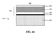
上記電極活性物質層、保護層、および任意のフィブリル含有層は、様々な形で配置してもよい。例えば、図4Aには、電気化学電池内に含まれてもよい(フィブリルを含有してもよい)多層保護構造体を含む電極(例えば、負極)の1つの例、例えば図1に示された電気化学電池(例えば、図1の負極112が、図4Aに示された電極410の形であってもよい)が示されている。図4Aに示された態様において、電極410は、電極活性物質層420(例えばリチウムなどの電気活性物質を含む層)および多層保護構造体422を含む。一般的に、保護層および/またはフィブリル含有層に沿った上記電極活性物質層は、まとめて「電極」と呼ばれる。すべてのそのような記載によって、本発明の一部を形成すると解されるべきである。この特定の態様において、多層保護構造体422は、(例えば、単一イオン伝導性材料を含有する)イオン伝導性層450、電極活性物質層およびイオン伝導性層の間に配置される高分子層440、並びに電極活性物質層および高分子層の間に配置される分離層430(例えば、電極のプラズマ処理から得られる層)を含む。多層構造体は、電気化学イオン(例えば、リチウムイオン)の通過を可能にし、かつ電極(例えば、負極)に損傷を与えるかもしれない他の成分の通過を妨害してもよい。以下により詳細に論じるように、有利に、多層構造体は欠陥の数を低減することができ、それによって、電極活性物質層表面の相当量を電流伝導に関与させ、高電流密度誘導表面欠陥を防止し、および/または電極をいくらかの種から保護するのに有効なバリアとして作用する。
The electrode active material layer, the protective layer, and the optional fibril-containing layer may be arranged in various forms. For example, FIG. 4A shows one example of an electrode (eg, negative electrode) that includes a multilayer protective structure that may be included in an electrochemical cell (which may contain fibrils), such as that shown in FIG. An electrochemical cell is shown (eg, negative electrode 112 of FIG. 1 may be in the form of
図4Aおよび本明細書中に記載された他の態様に示されたような電極(例えば、負極)は、多層構造体422の一部分として、(例えば、いくらかの態様において、フィブリルを含有してもよい単一イオン伝導性材料を含む)イオン伝導性層450を含んでもよい。いくつかの態様において、上記イオン伝導性層は非高分子層である。いくらかの態様において、上記イオン伝導性層は、金属イオン(例えば、リチウム金属イオン)に対して高伝導性であり、かつ電子に対して低伝導性である金属層によって一部または全体的に規定される。言い換えれば、金属イオン(例えば、リチウムイオン)を、電子または他のイオンが上記層を横切って通過することを防止することを可能とするように、上記イオン伝導性層が選択されてもよい。いくつかの態様において、上記イオン伝導性層は、金属イオン(例えば、リチウム金属イオン)に対して高伝導性であり、かつ電子に対して高伝導性(例えば、いくらかの態様において、イオンよりいっそう電子に対して高伝導性)である金属層によって一部または全体的に規定される。上記金属層は、金属合金層、例えば特にリチウム電極を用いる場合のリチウム化金属を含んでもよい。上記金属合金層のリチウム含有量は、例えば、上記金属合金層の金属の特定の選択、所望のリチウムイオン伝導度、および所望の可撓性に依存して、約0.5〜約20重量%の範囲で変化してもよい。上記イオン伝導性層(例えば、単一イオン伝導性材料を含む)に使用するのに好適な金属には、それらに限定されないが、アルミニウム、亜鉛、マグネシウム、銀、鉛、カドミウム、ビスマス、ガリウム、インジウム、ゲルマニウム、アンチモン、ヒ素および錫が挙げられる。時には、上記のものなどの金属の組み合わせを、イオン伝導性層に使用してもよい。 An electrode (eg, negative electrode) as shown in FIG. 4A and other embodiments described herein may also contain fibrils (eg, in some embodiments) as part of the multilayer structure 422. An ion conductive layer 450 (which includes a good single ion conductive material) may be included. In some embodiments, the ion conductive layer is a non-polymeric layer. In some embodiments, the ion conductive layer is defined in part or in whole by a metal layer that is highly conductive to metal ions (eg, lithium metal ions) and low conductivity to electrons. Is done. In other words, the ion conductive layer may be selected to allow metal ions (eg, lithium ions) to be prevented from passing electrons or other ions across the layer. In some embodiments, the ion conductive layer is highly conductive to metal ions (eg, lithium metal ions) and highly conductive to electrons (eg, in some embodiments, more than ions. Defined in part or in whole by a metal layer that is highly conductive to electrons). The metal layer may include a metal alloy layer, for example, a lithiated metal particularly when a lithium electrode is used. The lithium content of the metal alloy layer can be from about 0.5 to about 20% by weight, depending on, for example, the particular choice of metal in the metal alloy layer, the desired lithium ion conductivity, and the desired flexibility. It may be changed within the range. Suitable metals for use in the ion conductive layer (eg, including single ion conductive materials) include, but are not limited to, aluminum, zinc, magnesium, silver, lead, cadmium, bismuth, gallium, Indium, germanium, antimony, arsenic and tin. Sometimes, combinations of metals such as those described above may be used for the ion conductive layer.
他の態様において、上記イオン伝導性層は、セラミック層、例えば金属イオン(例えば、リチウムイオン)に対して伝導性であるイオン伝導性ガラス(例えば、単一イオン伝導性ガラス)を含んでもよい。好適なガラスには、それらに限定されないが、当該技術分野において知られているような「モディファイア(modifier)」部分と「ネットワーク(network)」部分を含むものとして特徴付けることができるものが挙げられる。上記モディファイアは、ガラス中で伝導性の金属イオンの金属酸化物を含んでもよい。上記ネットワーク部分は、例えば、金属酸化物や金属硫化物などの金属カルコゲン化物を含んでいてもよい。イオン伝導性層(例えば、単一イオン伝導性層)は、窒化リチウム、ケイ酸リチウム、ホウ酸リチウム、アルミン酸リチウム、リン酸リチウム、窒化リン酸リチウム、リチウムシリコスルフィド(lithium silicosulfides)、リチウムゲルマノスルフィド(lithium germanosulfide)、リチウム酸化物(例えば、Li2O、LiO、LiO2、LiRO2、ここでRは希土類金属である)、リチウムランタン酸化物、リチウムチタン酸化物、リチウムボロスルフィド(lithium borosulfides)、リチウムアルミノスルフィド(lithium aluminosulfides)およびリチウムホスホスルフィド(lithium phosphosulfides)、並びにこれらの組み合わせが挙げられる。1つの態様において、上記イオン伝導性層は、電解質の形の窒化リン酸リチウムを含む。 In other embodiments, the ion conductive layer may include a ceramic layer, such as an ion conductive glass (eg, a single ion conductive glass) that is conductive to metal ions (eg, lithium ions). Suitable glasses include, but are not limited to, those that can be characterized as including a “modifier” portion and a “network” portion as is known in the art. . The modifier may include a metal oxide of a conductive metal ion in glass. The network portion may contain a metal chalcogenide such as a metal oxide or a metal sulfide. The ion conductive layer (for example, a single ion conductive layer) includes lithium nitride, lithium silicate, lithium borate, lithium aluminate, lithium phosphate, lithium nitride phosphate, lithium silicosulfides, lithium germanium. Lithium germanosulfide, lithium oxide (eg Li 2 O, LiO, LiO 2 , LiRO 2 , where R is a rare earth metal), lithium lanthanum oxide, lithium titanium oxide, lithium borosulfide (lithium) borosulfides), lithium aluminosulphides and lithium phosphosulphides, and These combinations are mentioned. In one embodiment, the ion conductive layer comprises lithium nitride phosphate in the form of an electrolyte.
(例えば、多層構造体内のものなどの単一イオン伝導性材料層)イオン伝導性層の厚さは、いくらかの態様において、約1nm〜約10μmの範囲で変化してもよい。例えば、上記イオン伝導性層の厚さは、1〜10nm、10〜100nm、100〜1000nm、1〜5μm、または5〜10μmであってもよい。いくつかの態様において、イオン伝導性層の厚さは、例えば、10μm以下、5μm以下、1000nm以下、500nm以下、250nm以下、100nm以下、50nm以下、25nm以下、または10nm以下であってもよい。場合によって、上記イオン伝導性層は、多層構造体中の高分子層と同じ厚さを有する。 (Eg, a single ion conducting material layer such as in a multilayer structure) The thickness of the ion conducting layer may vary in a range from about 1 nm to about 10 μm in some embodiments. For example, the thickness of the ion conductive layer may be 1 to 10 nm, 10 to 100 nm, 100 to 1000 nm, 1 to 5 μm, or 5 to 10 μm. In some embodiments, the thickness of the ion conductive layer may be, for example, 10 μm or less, 5 μm or less, 1000 nm or less, 500 nm or less, 250 nm or less, 100 nm or less, 50 nm or less, 25 nm or less, or 10 nm or less. In some cases, the ion conductive layer has the same thickness as the polymer layer in the multilayer structure.
上記イオン伝導性層は、スパッタリング、電子ビーム蒸着、真空熱蒸着、レーザアブレーション、化学蒸着(CVD)、熱蒸着、プラズマ強化化学蒸着(PECVD)、レーザ強化化学蒸着およびジェット蒸着などの好適な方法によって被覆してもよい。用いられる上記技術は、被覆される材料の種類、層の厚さなどに依存してもよい。 The ion conductive layer is formed by a suitable method such as sputtering, electron beam evaporation, vacuum thermal evaporation, laser ablation, chemical vapor deposition (CVD), thermal evaporation, plasma enhanced chemical vapor deposition (PECVD), laser enhanced chemical vapor deposition, and jet vapor deposition. It may be coated. The technique used may depend on the type of material being coated, the thickness of the layer, and the like.
いくつかの態様において、イオン伝導性層(例えば、単一イオン伝導性層)は、イオン伝導性層のピンホールおよび/またはナノ細孔が高分子で充填されるように、高分子または(フィブリルを含有してもよい)他の材料で処理してもよい。そのような複合構造体は、例えば、そのような種が全体の多層配置に浸透して負極に到達するために通過する必要がある距離および屈曲度を増加することによって、いくらかの種(例えば、電解質および/またはポリスルフィド)の負極に対する拡散を防止することができる。 In some embodiments, the ion conductive layer (eg, a single ion conductive layer) is a polymer or (fibril) such that pinholes and / or nanopores of the ion conductive layer are filled with the polymer. May be treated with other materials. Such a composite structure may have some species (e.g., by increasing the distance and flexion that such species must pass to penetrate the entire multilayer arrangement and reach the negative electrode) Diffusion of the electrolyte and / or polysulfide) to the negative electrode can be prevented.
1つの態様において、イオン伝導性層(例えば、単一イオン伝導性層)に輸送抑制物質のモノマー前駆体を浸透させ、多孔性構造体をモノマーで効果的に充填し、上記モノマーを、単一イオン伝導性層の内側面に存在する高表面エネルギーによって、多孔性単一イオン伝導性層のナノ多孔性領域に送る。材料内の表面エネルギーが、通常の大気雰囲気処理において達成可能な値に対して、多くの場合高くなるように、上記モノマーを用いる処理の前に、上記イオン伝導性層を活性化法によって処理してもよい。 In one embodiment, an ion conductive layer (eg, a single ion conductive layer) is impregnated with a monomer precursor of a transport inhibitor, effectively filling the porous structure with the monomer, The high surface energy present on the inner surface of the ion conductive layer sends it to the nanoporous region of the porous single ion conductive layer. Before the treatment with the monomer, the ion-conducting layer is treated by an activation method so that the surface energy in the material is often higher than that achievable in normal atmospheric treatment. May be.
場合によっては、モノマー蒸気を上記イオン伝導性層において濃縮してもよく(例えば、単一イオン伝導性材料層)、それによって、上記イオン伝導性層の内側面に沿って送ることができ、そのような利用可能な曲がりくねった浸透のバイパスのすべてまたはいくらか有用な部分を上記モノマーで充填する。後続の硬化工程として、プラズマ処理または電子ビームのいずれかの光開始技術を、浸透したモノマーの重合のために導入してもよい。用いられた特定の硬化方法は、他の変数の中でも材料および層の厚さの特定の選択に依存する。 In some cases, the monomer vapor may be concentrated in the ion conductive layer (eg, a single ion conductive material layer), which can be routed along the inner surface of the ion conductive layer, All or some useful portion of such available torsion permeation bypass is filled with the monomer. As a subsequent curing step, either plasma treatment or electron beam photoinitiation techniques may be introduced for the polymerization of the penetrated monomer. The particular curing method used depends on the particular choice of material and layer thickness, among other variables.
輸送抑制物質として用いられる好適な材料には、特定の不必要な種の上記材料を通る輸送を完全にまたは部分的に抑制することが知られている(または簡易スクリーニングによって抑制することが測定される)材料を含む。前述のように、材料はまた、可撓性および/または強度を組み合わせる材料全体に加える特性を含む物理的特性にしたがって選択してもよい。材料の具体例には、前述のように、多層構造体中の層として用いられる本明細書中に記載された高分子、および/または他の高分子または他の種が挙げられる。配置全体に疎水性を望ましく付与する場合、1つの方法は、ある程度の疎水性を有する浸透輸送抑制物質を使用することである。 Suitable materials used as transport inhibitors are known to completely or partially inhibit transport through certain unwanted species of the above materials (or have been measured to be inhibited by simple screening). Include materials. As mentioned above, the material may also be selected according to physical properties, including properties added to the overall material that combine flexibility and / or strength. Specific examples of materials include the polymers described herein and / or other polymers or other species used as layers in a multilayer structure as described above. One method is to use an osmotic transport inhibitor that has some degree of hydrophobicity if it is desirable to impart hydrophobicity to the overall arrangement.
様々な手段によって、複合イオン伝導性構造体(例えば、単一イオン伝導性構造体)を形成してもよいが、いくつかの態様において、上記構造体を真空蒸着法および従来技術の製造方法において容易に入手可能な装置によって形成する。従って、スパッタリング、蒸発、電子ビーム蒸着、化学蒸着(CVD)、プラズマ強化CVDなどの様々な従来技術の蒸着源を用いて複合構造体を形成してもよい。モノマー蒸気源は同様に、それらに限定されないが、フラッシュ蒸着、ボート蒸着、真空モノマー技術(VMT)、ポリマー多層(PML)技術、透過膜またはモノマー蒸気を生成するのに有効であることがわかっている他の蒸気源からの蒸着を含む、従来技術の好適なモノマー蒸気源であってもよい。例えば、上記モノマー蒸気は、モノマー被覆の技術分野では既知のように、様々な浸透性金属フリットから生成してもよい。そのような方法は、米国特許第5,536,323号明細書(Kirlin)および米国特許第5,711,816号明細書(Kirlin)などに記載されている。 Composite ion conducting structures (eg, single ion conducting structures) may be formed by various means, but in some embodiments, the structures are used in vacuum deposition and prior art manufacturing methods. Formed by readily available equipment. Accordingly, the composite structure may be formed using a variety of prior art deposition sources such as sputtering, evaporation, electron beam evaporation, chemical vapor deposition (CVD), plasma enhanced CVD, and the like. Monomer vapor sources are also known to be effective in producing, but not limited to, flash deposition, boat deposition, vacuum monomer technology (VMT), polymer multilayer (PML) technology, permeable membranes or monomer vapors. It may be a suitable monomer vapor source of the prior art, including deposition from other vapor sources. For example, the monomer vapor may be generated from various permeable metal frits, as is known in the monomer coating art. Such methods are described, for example, in US Pat. No. 5,536,323 (Kirlin) and US Pat. No. 5,711,816 (Kirlin).
多層構造体422には、1つ以上の高分子層を含んでもよい。(例えば、多層構造体内の)高分子層の厚さは、約0.1〜約10μmの範囲内で変化してもよい。例えば、上記高分子層の厚さは、0.1〜1μm、1〜5μm、または5〜10μmであってもよい。高分子層の厚さは、例えば10μm以下、5μm以下、2.5μm以下、1μm以下、0.5μm以下、または0.1μm以下であってもよい。いくらかの態様において、上記高分子層はフィブリル材料、例えばセルロース系フィブリル材料または他の類似材料を含有する。 The multilayer structure 422 may include one or more polymer layers. The thickness of the polymer layer (eg, in the multilayer structure) may vary within the range of about 0.1 to about 10 μm. For example, the polymer layer may have a thickness of 0.1 to 1 μm, 1 to 5 μm, or 5 to 10 μm. The thickness of the polymer layer may be, for example, 10 μm or less, 5 μm or less, 2.5 μm or less, 1 μm or less, 0.5 μm or less, or 0.1 μm or less. In some embodiments, the polymer layer contains a fibril material, such as a cellulosic fibril material or other similar material.
一層より多い高分子層を有する多層構造体を含むいくらかの態様において、上記高分子層の厚さは、上記構造体内で変化してもよい。例えば、場合によっては、ベース電極材料層(例えば、リチウムリザーバ)に最も近い高分子層は、上記構造体の他の高分子層より厚い。好ましい態様は、例えば、リチウムイオンを、充電時に負極表面を横切って、より均一に沈着させることによって、負極を安定化することができる。 In some embodiments involving multilayer structures having more than one polymer layer, the thickness of the polymer layer may vary within the structure. For example, in some cases, the polymer layer closest to the base electrode material layer (eg, lithium reservoir) is thicker than the other polymer layers of the structure. In a preferred embodiment, the negative electrode can be stabilized by, for example, depositing lithium ions more uniformly across the negative electrode surface during charging.
いくらかの態様において、高分子層は単一イオンに対して伝導性を有するが、実質的に電気伝導性も有する高分子を含む。そのような材料の例には、リチウム塩(例えば、LiSCN、LiBr、LiI、LiClO4、LiAsF6、LiSO3CF3、LiSO3CH3、LiBF4、LiB(Ph)4、LiPF6、LiC(SO2CF3)3、およびLiN(SO2CF3)2)でドーピングされた(電子高分子または導電性高分子としても知られている)電気伝導性高分子が挙げられる。導電性高分子は、当該技術分野で知られており、このような高分子の例には、それらに限定されないが、ポリ(アセチレン)類、ポリ(ピロール)類、ポリ(チオフェン)類、ポリ(アニリン)類、ポリ(フルオレン)類、ポリナフタレン類、ポリ(p−フェニレンスルフィド)、およびポリ(p−フェニレンビニレン)類が挙げられる。電気伝導性添加剤を、電気伝導性高分子を形成する高分子に添加してもよい。いくらかの電気伝導性材料は、例えば10−2S/cm、10−1S/cm、1S/cm、101S/cm、102S/cm、103S/cm、104S/cm、または105S/cmより高い伝導率を有してもよい。 In some embodiments, the polymer layer comprises a polymer that is conductive to a single ion but also has substantial electrical conductivity. Examples of such materials include lithium salts (eg, LiSCN, LiBr, LiI, LiClO 4 , LiAsF 6 , LiSO 3 CF 3 , LiSO 3 CH 3 , LiBF 4 , LiB (Ph) 4 , LiPF 6 , LiC ( SO 2 CF 3 ) 3 , and electrically conductive polymers doped with LiN (SO 2 CF 3 ) 2 ) (also known as electronic or conductive polymers). Conductive polymers are known in the art and examples of such polymers include, but are not limited to, poly (acetylenes), poly (pyrroles), poly (thiophenes), poly (Aniline) s, poly (fluorenes), polynaphthalenes, poly (p-phenylene sulfide), and poly (p-phenylene vinylene) s. An electrically conductive additive may be added to the polymer that forms the electrically conductive polymer. Some electrically conductive materials are for example 10 −2 S / cm, 10 −1 S / cm, 1 S / cm, 10 1 S / cm, 10 2 S / cm, 10 3 S / cm, 10 4 S / cm. Or a conductivity higher than 10 5 S / cm.
いくらかの態様において、高分子層は、1種以上のイオンに対して伝導性を有するが、実質的に非電気伝導性である。実質的に非電気伝導性であるイオン伝導性種の例には、リチウム塩でドーピングされた非電気伝導性材料(例えば、電気絶縁材料)が挙げられる。
例えば、リチウム塩でドーピングされている、アクリレート、ポリエチレンオキシド、シリコーン、ポリ塩化ビニル、および他の絶縁性高分子は、イオン伝導性とすることができるが、実質的に非電気伝導性である。
In some embodiments, the polymer layer is conductive to one or more ions but is substantially non-electrically conductive. Examples of ionically conductive species that are substantially non-electrically conductive include non-electrically conductive materials (eg, electrically insulating materials) doped with lithium salts.
For example, acrylates, polyethylene oxide, silicones, polyvinyl chloride, and other insulating polymers that are doped with lithium salts can be ionically conductive but are substantially non-electrically conductive.
いくつかの態様において、単一イオン伝導性材料を含むイオン伝導性材料は、非高分子材料を含んでもよい。いくらかの非電気伝導性材料は、103Ω・cm、104Ω・cm、105Ω・cm、106Ω・cm、107Ω・cm、または108Ω・cmより高い抵抗率を有してもよい。 In some embodiments, the ion conductive material including a single ion conductive material may include a non-polymeric material. Some non-electrically conductive materials have a resistivity higher than 10 3 Ω · cm, 10 4 Ω · cm, 10 5 Ω · cm, 10 6 Ω · cm, 10 7 Ω · cm, or 10 8 Ω · cm. You may have.
いくつかの態様において、多層構造体に用いるのに好適な高分子層には、リチウムに対して高伝導性であり、かつ電子に対して低伝導性である高分子を含む。そのような高分子の例には、イオン伝導性高分子、スルホン化高分子、および炭化水素高分子が挙げられる。上記高分子の選択は、電解質の特性および電池に用いられる正極などの多くの因子に依存する。好適なイオン伝導性高分子には、例えば、リチウム電気化学電池用の固体高分子電解質およびゲル高分子電解質に有用であることが知られているイオン伝導性高分子、例えば、ポリエチレンオキシドが挙げられる。好適なスルホン化高分子は、例えば、スルホン化シロキサンポリマー、スルホン化ポリスチレン‐エチレン‐ブチレンポリマー、およびスルホン化ポリスチレンポリマーが挙げられる。好適な炭化水素高分子には、例えば、エチレン‐プロピレンポリマー、ポリスチレンポリマーなどが挙げられる。 In some embodiments, polymer layers suitable for use in the multilayer structure include polymers that are highly conductive to lithium and low conductive to electrons. Examples of such polymers include ion conducting polymers, sulfonated polymers, and hydrocarbon polymers. The selection of the polymer depends on many factors such as the characteristics of the electrolyte and the positive electrode used in the battery. Suitable ion conducting polymers include, for example, ion conducting polymers known to be useful in solid and gel polymer electrolytes for lithium electrochemical cells, such as polyethylene oxide. . Suitable sulfonated polymers include, for example, sulfonated siloxane polymers, sulfonated polystyrene-ethylene-butylene polymers, and sulfonated polystyrene polymers. Suitable hydrocarbon polymers include, for example, ethylene-propylene polymers, polystyrene polymers, and the like.
多層構造体の高分子層はまた、アルキルアクリレート、グリコールアクリレート、ポリグリコールアクリレート、ポリグリコールビニルエーテル、ポリグリコールジビニルエーテル、および共同譲受人のYingらの米国特許第6,183,901号明細書に記載されているようなセパレータ層の保護コーティング層用のものなどのモノマーの重合から形成される架橋高分子材料を含んでもよい。例えば、1つのそのような架橋高分子は、ポリジビニルポリ(エチレングリコール)である。上記架橋高分子材料は、更に、イオン伝導性を高めるために、例えば、リチウム塩などの塩を含んでもよい。1つの態様において、多層構造体の高分子層は架橋高分子を含有する。 The polymer layers of the multilayer structure are also described in alkyl acrylates, glycol acrylates, polyglycol acrylates, polyglycol vinyl ethers, polyglycol divinyl ethers, and co-assigned Ying et al. US Pat. No. 6,183,901. Crosslinked polymeric materials formed from the polymerization of monomers such as those for the protective coating layer of the separator layer may also be included. For example, one such crosslinked polymer is polydivinyl poly (ethylene glycol). The crosslinked polymer material may further contain, for example, a salt such as a lithium salt in order to increase the ionic conductivity. In one embodiment, the polymer layer of the multilayer structure contains a crosslinked polymer.
高分子層に使用するのに好適な他の種類の高分子には、それらに限定されないが、ポリアミン(例えば、ポリ(エチレンイミン)およびポリプロピレンイミン(PPI));ポリアミド(例えば、ポリアミド(ナイロン)、ポリ(ε−カプロラクタム)(ナイロン6)、ポリ(ヘキサメチレンアジパミド)(ナイロン66))、ポリイミド(例えば、ポリイミド、ポリニトリル、およびポリ(ピロメリットイミド‐1,4‐ジフェニルエーテル)(Kapton));ビニルポリマー(例えば、ポリアクリルアミド、ポリ(2−ビニルピリジン)、ポリ(N−ビニルピロリドン)、ポリ(メチルシアノアクリレート)、ポリ(エチルシアノアクリレート)、ポリ(ブチルシアノアクリレート)、ポリ(イソブチネシアノアクリレート)、ポリ(酢酸ビニル)、ポリ(ビニルアルコール)、ポリ(塩化ビニル)、ポリ(フッ化ビニル)、ポリ(2−ビニルピリジン)、ビニルポリマー、ポリクロロトリフルオロエチレン、およびポリ(イソヘキシルシアノアクリレート));ポリアセタール;ポリオレフィン(例えば、ポリ(ブテン‐1)、ポリ(n‐ペンテン‐2)、ポリプロピレン、ポリテトラフルオロエチレン);ポリエステル(例えば、ポリカーボネート、ポリブチレンテレフタレート、ポリヒドロキシブチレート);ポリエーテル
(ポリ(エチレンオキシド)(PEO)、ポリ(プロピレンオキシド)(PPO)、ポリ(テトラメチレンオキシド)(PTMO));ビニリデンポリマー(例えば、ポリイソブチレン、ポリ(メチルスチレン)、ポリ(メチルメタクリレート)(PMMA)、ポリ(塩化ビニリデン)、ポリ(フッ化ビニリデン));ポリアラミド(例えば、ポリ(イミノ‐1,3‐フェニレンイミノイソフタロイル)およびポリ(イミノ‐1,4‐フェニレンイミノテレフタロイル));ポリヘテロ芳香族化合物(例えば、ポリベンズイミダゾール(PBI)、ポリベンゾビスオキサゾール(PBO)、ポリベンゾビスチアゾール(PBT));多複素環化合物(例えば、ポリピロール);ポリウレタン;フェノール系ポリマー(例えば、フェノール‐ホルムアルデヒド);ポリアルキン(例えば、ポリアセチレン);ポリジエン(例えば、1,2‐ポリブタジエン、シスまたはトランス‐1,4‐ポリブタジエン);ポリシロキサン(例えば、ポリ(ジメチルシロキサン)(PDMS)、ポリ(ジエチルシロキサン)(PDES)、ポリジフェニルシロキサン(PDPS)、およびポリメチルフェニルシロキサン(PMPS));および無機ポリマー(例えば、ポリホスファゼン、ポリホスホネート、ポリシラン、ポリシラザン)が挙げられる。
Other types of polymers suitable for use in the polymer layer include, but are not limited to, polyamines (eg, poly (ethyleneimine) and polypropyleneimine (PPI)); polyamides (eg, polyamide (nylon)) , Poly (ε-caprolactam) (nylon 6), poly (hexamethylene adipamide) (nylon 66)), polyimide (eg, polyimide, polynitrile, and poly (pyromellitimide-1,4-diphenyl ether) (Kapton) ); Vinyl polymers (eg, polyacrylamide, poly (2-vinylpyridine), poly (N-vinylpyrrolidone), poly (methyl cyanoacrylate), poly (ethyl cyanoacrylate), poly (butyl cyanoacrylate), poly (iso Butynecyanoacrylate), poly Vinyl acetate), poly (vinyl alcohol), poly (vinyl chloride), poly (vinyl fluoride), poly (2-vinylpyridine), vinyl polymers, polychlorotrifluoroethylene, and poly (isohexyl cyanoacrylate)); Polyacetals; polyolefins (eg, poly (butene-1), poly (n-pentene-2), polypropylene, polytetrafluoroethylene); polyesters (eg, polycarbonate, polybutylene terephthalate, polyhydroxybutyrate); polyethers (poly (Ethylene oxide) (PEO), poly (propylene oxide) (PPO), poly (tetramethylene oxide) (PTMO)); vinylidene polymers (eg, polyisobutylene, poly (methylstyrene), poly (methyl methacrylate) (PMMA), poly (vinylidene chloride), poly (vinylidene fluoride)); polyaramid (eg, poly (imino-1,3-phenyleneiminoisophthaloyl) and poly (imino-1,4-phenyleneiminoterephthaloyl) )); Polyheteroaromatic compounds (eg, polybenzimidazole (PBI), polybenzobisoxazole (PBO), polybenzobisthiazole (PBT)); polyheterocyclic compounds (eg, polypyrrole); polyurethanes; phenolic polymers ( For example, phenol-formaldehyde); polyalkynes (eg, polyacetylene); polydienes (eg, 1,2-polybutadiene, cis or trans-1,4-polybutadiene); polysiloxanes (eg, poly (dimethylsiloxane) (PDMS), poly (The Chill siloxane) (PDES), polydiphenylsiloxane (PDPS), and polymethylphenylsiloxane (PMPS)); and inorganic polymers (e.g., polyphosphazene, polyphosphonates, polysilane, polysilazane) can be mentioned.
前述のおよび本明細書中に記載された高分子材料は、イオン伝導性を向上させるために、リチウム塩(例えば、LiSCN、LiBr、LiI、LiClO4、LiAsF6、LiSO3CF3、LiSO3CH3、LiBF4、LiB(Ph)4、LiPF6、LiC(SO2CF3)3、およびLiN(SO2CF3)2)などの塩を更に含んでもよい。 The polymeric materials described above and herein can be prepared using lithium salts (eg, LiSCN, LiBr, LiI, LiClO 4 , LiAsF 6 , LiSO 3 CF 3 , LiSO 3 CH to improve ionic conductivity. 3 , LiBF 4 , LiB (Ph) 4 , LiPF 6 , LiC (SO 2 CF 3 ) 3 , and LiN (SO 2 CF 3 ) 2 ).
高分子層を、電子ビーム蒸着、真空熱蒸着、レーザアブレーション、化学蒸着、熱蒸着、プラズマ支援化学真空蒸着、レーザ強化化学蒸着、ジェット蒸着、および押出などの方法によって被覆してもよい。高分子層はまた、スピンコーティング技術によって被覆してもよい。架橋高分子層を被覆する方法には、例えばYializisの米国特許第4,954,371号明細書に記載されたフラッシュ蒸着法を含む。リチウム塩を含む架橋高分子層を被覆する方法には、例えば、Affinitoらの米国特許第5,681,615号明細書に記載されたフラッシュ蒸着法を含んでもよい。高分子層を被覆するのに用いられる技術は、被覆される材料の種類、層の厚さなどに依存する。 The polymer layer may be coated by methods such as electron beam evaporation, vacuum thermal evaporation, laser ablation, chemical vapor deposition, thermal vapor deposition, plasma assisted chemical vacuum deposition, laser enhanced chemical vapor deposition, jet vapor deposition, and extrusion. The polymer layer may also be coated by spin coating techniques. Methods for coating the crosslinked polymer layer include, for example, the flash deposition method described in US Pat. No. 4,954,371 to Yializis. Methods for coating a crosslinked polymer layer containing a lithium salt may include, for example, the flash deposition method described in US Pat. No. 5,681,615 to Affinito et al. The technique used to coat the polymer layer depends on the type of material being coated, the thickness of the layer, and the like.
図4Aに関する説明において前述のように、1つの特定の態様において、電極活性物質層420を電解質460から分離する上記保護構造体は、電極活性物質層または分離層430に隣接する高分子層を含む。他の配置において、高分子層はベース電極材料層または分離層に隣接する第一の層である必要はない。様々な多層構造体を含む様々な層配置が、以下に記載されており、ベース電極材料層に隣接する第一の層は高分子であっても、またはなくてもよい。特定の層配置を示す全ての配置において、層の順序の入れ替えは本発明の範囲内であると解されるべきである。これにもかかわらず、本発明の1つの態様には、電極活性物質層または分離層に隣接する非脆弱高分子によって実現される特定の優位性を含む。
As described above in the description of FIG. 4A, in one particular embodiment, the protective structure that separates the electrode
いくつかの態様において、多層構造体は、上記構造体中に含まれる個々の層より良好である電極活性物質層を保護する。例えば、多層構造体の各層(例えば、イオン伝導性層(例えば、単一イオン伝導性層)、高分子層、および/または分離層)は所望の特性を有してもよいが、同時に、異なる特性を有する他の成分によって補完される場合に、最も有効であってもよい。例えば、イオン伝導性層(例えば、単一イオン伝導性層)、特に真空蒸着されたイオン伝導性層(例えば、真空蒸着された単一イオン伝導性層)は、薄膜として可撓性を有してもよいが、より厚い層として被覆される場合に、ピンホールおよび/または凹凸などの欠陥を有してもよく、取り扱い時に亀裂を生じてもよい。高分子層、および特に架橋高分子層は、例えば非常に平滑な表面を提供することができ、強度および可撓性を付与し、電子絶縁性であるが、いくらかの溶媒および/または液体電解質を通過させる。従って、これらは、改良された保護構造体層全体において互いを補完することができる層の例である。 In some embodiments, the multilayer structure protects the electrode active material layer that is better than the individual layers included in the structure. For example, each layer of a multilayer structure (eg, an ion conductive layer (eg, a single ion conductive layer), a polymer layer, and / or a separation layer) may have desired properties, but at the same time different It may be most effective when supplemented by other components having properties. For example, an ion conductive layer (eg, a single ion conductive layer), particularly a vacuum deposited ion conductive layer (eg, a vacuum deposited single ion conductive layer) has flexibility as a thin film. However, when coated as a thicker layer, it may have defects such as pinholes and / or irregularities and may crack during handling. The polymer layer, and particularly the crosslinked polymer layer, can provide, for example, a very smooth surface, provides strength and flexibility, is electronically insulating, but does not contain any solvent and / or liquid electrolyte. Let it pass. Thus, these are examples of layers that can complement each other in the entire improved protective structure layer.
多層電極保護構造体は、種が層中の欠陥またはオープンスペース通って拡散する傾向があるので、電極活性物質層への種(例えば、電解質およびポリスルフィド種)の直接の流れを減少することによって、優れた透過バリアとして作用することができる。従って、樹状突起の形成、自己放電、およびサイクル寿命の損失を低減することができる。 Multi-layer electrode protection structures can reduce the direct flow of species (eg, electrolytes and polysulfide species) to the electrode active material layer as species tend to diffuse through defects or open spaces in the layer. It can act as an excellent transmission barrier. Thus, dendrite formation, self-discharge, and cycle life loss can be reduced.
多層構造体の他の優位性には、構造体の機械的特性を含む。イオン伝導性層(例えば、単一イオン伝導性層)に隣接する高分子層(例えば、任意にフィブリルを含有する)の位置決めは、上記イオン伝導層に亀裂がはいる傾向を減少させることができ、上記構造体のバリア性を高めることができる。従って、これらの積層体は、高分子層を介在させない構造体よりも製造工程時の取り扱いによる応力に対してより強固であることができる。また、多層保護層は、電池の充放電のサイクルの間に、ベース電極材料層から前後へのリチウムの移行に伴う体積変化に対する向上した耐性を有することができる。 Other advantages of the multilayer structure include the mechanical properties of the structure. Positioning of a polymer layer (eg, optionally containing fibrils) adjacent to an ion conductive layer (eg, a single ion conductive layer) can reduce the tendency of the ion conductive layer to crack. The barrier property of the structure can be improved. Accordingly, these laminates can be more robust against stress due to handling during the manufacturing process than structures having no polymer layer interposed. The multilayer protective layer can also have improved resistance to volume changes associated with lithium migration from the base electrode material layer back and forth during the battery charge / discharge cycle.
電極活性物質層(例えば、電解質および/またはポリスルフィド)に損傷を与える可能性のあるいくらかの種の電極活性物質層に到達する能力はまた、多層構造体中におけるイオン伝導性層(例えば、単一イオン伝導性層)および高分子層(例えば、任意にフィブリルを含有する)の繰り返し層を提供することによって、低減することができる。種がイオン伝導性層の欠陥のない部分に遭遇すると、上記種が非常に薄い高分子層を通って横方向に拡散して、第2のイオン伝導性層(例えば、単一イオン伝導性層)において欠陥に遭遇する場合に、電極活性物質層への上記種の輸送が可能となる。極薄層を通るそのような横方向の拡散は非常に遅いので、イオン伝導性層/高分子層の対の数が増加するにつれて、種の拡散速度は非常に小さくなる(例えば、上記層を横切る浸透量は減少する)。例えば、1つの態様において、高分子層/イオン伝導性層/高分子層の3層構造体を通る種の浸透は、単一イオン伝導性層のみより、3桁分低減することができる(例えば、それらの層だけは乏しいバリア性を有するのだが)。別の態様において、高分子層/イオン伝導性層/高分子層/イオン伝導性層/高分子層の5層構造体は、単一イオン伝導性層中に比較して、種の浸透の5桁分の低減を有する。対照的に、2倍厚のイオン伝導性層を通る同様種の浸透は、実際に増加する。電極保護層を通る有害な種の浸透のかなりの低減は、個々の層の厚さが減少する場合に層の数が増加するのに伴って、向上される。即ち、特定の全体厚さのイオン伝導性層および高分子層の2層構造体に比べて、同様の全体厚さのイオン伝導性層および高分子層の交互の10層構造体は、上記層を通る望ましくない種の浸透をかなり減少したものに変える。本明細書中に記載された電極安定化保護構造体によって実現される重要な優位性により、従来技術の構造体に比べて、より少ない全材料量を特定の保護構造体に用いることができる。従って、特定の電池配置に必要な特定レベルの電極保護において、かなり少量の全電極安定化材料を使用することができ、全電池重量をかなり低減する。 The ability to reach some species of electrode active material layer that can damage the electrode active material layer (eg, electrolytes and / or polysulfides) is also an ion conductive layer (eg, a single layer) in a multilayer structure. This can be reduced by providing a repeating layer of an ion conductive layer) and a polymer layer (eg, optionally containing fibrils). When the species encounters a defect-free portion of the ion conductive layer, the species diffuses laterally through the very thin polymer layer to form a second ion conductive layer (eg, a single ion conductive layer). ), The above kind of transport to the electrode active material layer becomes possible. Such lateral diffusion through ultrathin layers is so slow that as the number of ion-conducting / polymer layer pairs increases, the rate of seed diffusion becomes very small (eg, The amount of permeation across it decreases). For example, in one embodiment, the penetration of species through a three layer structure of polymer layer / ion conducting layer / polymer layer can be reduced by three orders of magnitude over a single ion conducting layer alone (eg, Only those layers have poor barrier properties). In another embodiment, a five layer structure of polymer layer / ion conducting layer / polymer layer / ion conducting layer / polymer layer has a 5% species penetration compared to a single ion conducting layer. Has a reduction of orders of magnitude. In contrast, the penetration of similar species through a double-thick ion conducting layer is actually increased. The considerable reduction of harmful species penetration through the electrode protection layer is improved as the number of layers increases as the thickness of the individual layers decreases. That is, as compared with a two-layer structure of an ion conductive layer and a polymer layer having a specific total thickness, an alternating ten-layer structure of an ion conductive layer and a polymer layer having a similar total thickness is To reduce the penetration of undesirable species through Due to the significant advantages realized by the electrode stabilizing protection structure described herein, a lower total amount of material can be used for a particular protection structure compared to prior art structures. Thus, a fairly small amount of total electrode stabilization material can be used at the specific level of electrode protection required for a specific battery arrangement, significantly reducing the total battery weight.
多層構造体には、必要に応じて、様々な多くの高分子/イオン伝導性(単一イオン伝導性)の対を含んでもよい。一般的には、多層構造体は、n個の高分子/イオン伝導性の対(ここで、nは電池用の特定の性能基準に基づき決定することができる)を有してもよい。例えば、nは、1以上、或いは2、3、4、5、6、7、10、15、20、40、60、100、または1000以上の整数であってもよい。いくつかの態様において、多層構造体には、4、10、25、50、100、200、500、1000、2000、3000、5000、または8000を超える高分子/イオン伝導性の対を有してもよい。例えば、1つの特定の態様において、10,000を超える高分子/イオン伝導性の対を製造した。 The multilayer structure may include a number of different polymer / ionic conducting (single ionic conducting) pairs as desired. In general, a multilayer structure may have n polymer / ion conducting pairs, where n can be determined based on specific performance criteria for the battery. For example, n may be an integer greater than or equal to 1, or 2, 3, 4, 5, 6, 7, 10, 15, 20, 40, 60, 100, or 1000 or greater. In some embodiments, the multilayer structure has more than 4, 10, 25, 50, 100, 200, 500, 1000, 2000, 3000, 5000, or 8000 polymer / ion conducting pairs. Also good. For example, in one particular embodiment, over 10,000 polymer / ion conducting pairs were produced.
図4Bには、多数の高分子およびイオン伝導性(例えば、単一イオン伝導性)層(更に、それらの内のいずれかがフィブリルを含有してもよい)を含む多層電極保護構造体の例を示す。図4Bに示された態様において、負極411は、(例えば、リチウムなどの電気活性物質を含む)電極活性物質層420、並びに電池のベース電極材料層および電解質460の間に配置された多層構造体424を含む。上記多層構造体は、それぞれイオン伝導性層(例えば、単一イオン伝導性材料層)の少なくとも2つの第一層並びに(いくらかの態様において、フィブリル含有層であってもよい)それぞれ高分子材料の少なくとも2つの第二層を含む。例えば、多層構造体424は、(フィブリル含有層であってもよい)高分子層440および442、並びにイオン伝導性層450および452を含む。図4Bに示すように、高分子材料の2層およびイオン伝導性材料の2層を、互いに対して交互に配置する。負極411は、任意に、ベース電極材料層および高分子層の間分離層(例えば、プラズマ処理層)を含んでもよい(図4Bには表示せず;図4Aに表示)。
FIG. 4B illustrates an example of a multi-layer electrode protection structure that includes multiple polymers and ion conductive (eg, single ion conductive) layers (and any of which may contain fibrils). Indicates. In the embodiment shown in FIG. 4B, the
負極411はまた、高分子層444および446、並びに(いくつかの態様において、フィブリル含有層であってもよい)イオン伝導性層454および456を含む、多層構造体426などの更なる多層構造体を含んでもよい。多層構造体424および426を組み合わせて単一多層構造体を形成してもよく、または多層構造体424および426は、それぞれイオン伝導性材料の4層およびそれぞれ高分子材料の4層を含む1つの単位多層構造体として共に構成してもよい。他の態様において、構造体は、他の多くのイオン伝導性層および高分子層の交互層を含んでもよい。例えば、多層構造体は、それぞれイオン伝導性材料のn個の第一層およびそれぞれ高分子材料n個の第二層(ここで、nは2以上である)を交互の配置で含んでもよい。例えば、nは、少なくとも2、3、4、5、6、7、10、15、20、40、60、100などであってもよい。
The
他の態様において、多層構造体は、イオン伝導性層(例えば、単一イオン伝導性材料層)より多くの高分子層(それらの1つ以上がフィブリルを含有してもよい)を含んでもよく、または高分子層より多くのイオン伝導性層(例えば、単一イオン伝導性材料層)を含んでもよい。例えば、多層構造体は、n個の高分子層およびn+1個のイオン伝導性層を含んでもよく、またはn個のイオン伝導性層およびn+1個の高分子層を含んでもよい(ここで、nは2以上である)。例えば、nは、少なくとも2、3、4、5、6、または7などであってもよい。しかしながら、前述のように、少なくとも1つの高分子層に隣接し、イオン伝導性層の少なくとも50%、70%、90%、または95%において、そのような層は両側で高分子層と隣接している。 In other embodiments, the multilayer structure may include more polymer layers (one or more of which may contain fibrils) than an ion conductive layer (eg, a single ion conductive material layer). Or more ion conductive layers (eg, a single ion conductive material layer) than the polymer layer. For example, the multilayer structure may include n polymer layers and n + 1 ion conductive layers, or may include n ion conductive layers and n + 1 polymer layers, where n Is 2 or more). For example, n may be at least 2, 3, 4, 5, 6, 7 or the like. However, as described above, adjacent to at least one polymer layer and in at least 50%, 70%, 90%, or 95% of the ion conductive layer, such layer is adjacent to the polymer layer on both sides. ing.
前述のように、多層電極保護構造体は、構造体を規定する特定量の材料をより薄い形で、およびより多く配置する場合、かなりの優位性を提供することができる。いくつかの態様において、多層構造体の各層は、100μm未満、50μm未満、25μm未満、10μm未満、1μm未満、100nm未満、10nm未満、または1nm未満の最大厚さを有する。時には、層の単層厚さが、多層構造体中で同一であってもよい。例えば、図4Bの高分子層440および442は、多層構造体424中で同一厚さを有してもよい。他の態様において、単一層型の層の厚さは、多層構造体中のものと異なってもよく、例えば高分子層440および442は多層構造体424中で異なる厚さを有してもよい。場合によっては、多層構造体中の異なるタイプの層の厚さは同一であっても、または他の場合には、異なってもよい。例えば、高分子層440および442の厚さは、イオン伝導性層450および452と異なってもよい。当業者であれば、本明細書中の記載と組み合わせて、適当な材料および層の厚さを選択することができる。
As mentioned above, multilayer electrode protection structures can provide significant advantages when the particular amount of material defining the structure is placed in a thinner form and more. In some embodiments, each layer of the multilayer structure has a maximum thickness of less than 100 μm, less than 50 μm, less than 25 μm, less than 10 μm, less than 1 μm, less than 100 nm, less than 10 nm, or less than 1 nm. Sometimes the monolayer thickness of the layers may be the same in the multilayer structure. For example, the polymer layers 440 and 442 of FIG. 4B may have the same thickness in the
多層構造体は、例えば、電気化学電池の電解質、対向電極、または特定の用途に依存する様々な全体厚さを有してもよい。場合によっては、多層構造体は、5mm以下、1mm以下、700μm以下、300μm以下、250μm以下、200μm以下、150μm以下、100μm以下、75μm以下、または50μm以下の全体厚さを有してもよい。いくらかの高分子/イオン伝導性材料の対を有するいくらかの厚さを有する多層構造体を有することも望ましい。例えば、1つの態様において、多層構造体は、1mm未満の厚さを有してもよく、かつ10個の高分子/イオン伝導性材料の対を含んでもよい。他の態様において、多層構造体は、0.5mm未満の厚さを有してもよく、かつ50個の高分子/イオン伝導性材料の対を含んでもよい。本明細書中に記載されるように、全体の電極安定化厚さ、個々の層の厚さ、個々の層数などの特定の組み合わせをそれぞれ含む様々な態様が提供されてもよいと解されるべきである。 The multilayer structure may have various overall thicknesses depending on, for example, the electrolyte of the electrochemical cell, the counter electrode, or the particular application. In some cases, the multilayer structure may have an overall thickness of 5 mm or less, 1 mm or less, 700 μm or less, 300 μm or less, 250 μm or less, 200 μm or less, 150 μm or less, 100 μm or less, 75 μm or less, or 50 μm or less. It is also desirable to have a multilayer structure having some thickness with some polymer / ion conducting material pairs. For example, in one embodiment, the multilayer structure may have a thickness of less than 1 mm and may include 10 polymer / ion conducting material pairs. In other embodiments, the multilayer structure may have a thickness of less than 0.5 mm and may include 50 polymer / ion conducting material pairs. As described herein, it is understood that various aspects may be provided, each including a specific combination of overall electrode stabilization thickness, individual layer thickness, number of individual layers, etc. Should be.
別の態様において、(例えば、イオン伝導性層(例えば単一イオン伝導性材料層)などの保護層の)埋め込み層を、2つの電極活性物質の層の間に配置する。これは、「ラマノード(lamanode)」構造体と呼ばれる。図4Cには、電極活性物質層420(例えば、リチウムリザーバとも呼ばれる、リチウム)の第一層、埋め込み層470、および層420(例えば、作用リチウム層)と同一電極活性物質を含む第二層423を含む代表的な負極412を示す。図4Cの態様に示されるように、上記第二層を、電極活性物質層420および電解質460の間に配置する。上記第二層は、上記電解質に直接接触していても、または何らかの形の表面層(例えば、本明細書中に記載されたような電極安定化構造体または多層構造体)を介して上記電解質と直接接触していてもよい。埋め込み層470によって分離された各ベース電極活性物質層を有する2層構造体の機能は、以下の記載からより明確なものとなる。本明細書中の記載において、層470が示され、「埋め込み層」として記載されているが、上記層は部分的に、または完全に埋め込まれている必要はない。多くの場合またはほとんどの場合、層470は、ベース電極活性物質によって各面に被覆された実質的に薄い、2面構造体であるが、端部においてはベース電極活性物質によって覆われていない。
In another embodiment, a buried layer (eg, of a protective layer such as an ion conductive layer (eg, a single ion conductive material layer)) is disposed between two layers of electrode active material. This is called a “lamanode” structure. 4C illustrates a first layer of electrode active material layer 420 (eg, lithium, also referred to as a lithium reservoir), a buried
一般的に、図4Cに示される配置の作動において、電極の第二層のいくらかまたは全部が、充電により(電解質中に入るリチウムイオンに変換される時に)電極から「失われる」。充電により、リチウムイオンがリチウム金属として負極上にめっきされると、部分423(または第二層423のすくなくともいくらかの部分)として、層470の上にめっきされる。当業者は、本明細書中に記載されたような電気化学電池において、上記電池の各充放電サイクルにおいて失われる全体として少量のリチウムが存在する。図4Cに示された配置において、層423(または層423の大部分)の厚さは、層423のほとんどまたは全部が、上記電池の完全充電によって失われる(対向電極の完全「充足」;当業者に理解される制限によって、対向電極が充電工程に関与しなくなる点)ように選択されてもよい。
In general, in operation of the arrangement shown in FIG. 4C, some or all of the second layer of the electrode is “lost” from the electrode (when converted to lithium ions entering the electrolyte) upon charging. When lithium ions are plated on the negative electrode as lithium metal by charging, it is plated on
いくらかの態様において、層470は、金属イオン(例えば、Li+イオン)に対して伝導性であるように選択される。上記埋め込み層は、高い金属イオン(例えば、リチウムイオン)流量によって上部電極活性物質層表面を損傷するので、第一サイクルの底部電極活性物質層(例えば、リチウム層)を損傷から保護する。従って、一旦、層423のすべてが特定の充電サイクルにおいて消費されると、更なる放電によって、層420からの電極活性物質(例えば、リチウム)の酸化、層470を通る金属イオン(例えば、リチウムイオン)の通過、および電解質への金属イオン(例えば、リチウムイオン)の放出につながる。もちろん、層423は、全てまたはほとんど全てを第一放電において消費するように、特定量である必要はない。電極活性物質(例えば、リチウム)を層420から層470を通って電解質中に引き入れることが必要となるように、様々な充放電サイクルおよび各サイクルによって失われる本来の少量のリチウムを用いてもよい。しかしながら、一旦起こると、次いで、一般的にそれぞれ次の充放電サイクルが以下の通り進行する。
In some embodiments,
いくらかの態様において、ほとんどの放電サイクルによって、電極活性物質(例えば、リチウム)は、放電サイクルの最終において、層423から除去され、少量の電極活性物質(例えば、リチウム)が層470を通って区域420から引き出されて、最近の充放電サイクルにおいて失われた電極活性物質の量を埋め合わせする。充電時に、電極活性物質(例えば、リチウム)が層470上に物質423として、放電時に負極から除去されるより非常にわずかに少ない量で、めっきされてもよい。電極保護層であってもよい上記埋め込み層を、本明細書中に記載された機能に従って、当業者によって選択される、如何なる好適な材料から製造してもよい。一般的に、層470を、イオン伝導性(例えば、単一イオン伝導性)であるが、電極活性物質(例えば、リチウム金属)自体は通過させない材料から製造する。いくつかの態様において、上記材料は、後述の理由により、電気非伝導性である。
In some embodiments, most discharge cycles cause the electrode active material (eg, lithium) to be removed from
電極活性物質の第一層および第二層(例えば、図4Cにおける層420および423)の厚さの比は、例えば第一放電の必要な「放電深さ」(消費された電極活性物質の量)に基づいて、計算することができる。上記比は、例えば0.2〜0.4の範囲内であってもよい。負極層420の厚さは、例えば100μm未満、50μm未満、25μm未満、または10μm未満であってもよい。いくつかの態様において、負極層420は、厚さ10〜30μmを有してもよい。
The thickness ratio of the first and second layers of electrode active material (eg, layers 420 and 423 in FIG. 4C) is, for example, the required “discharge depth” of the first discharge (the amount of electrode active material consumed). ). The ratio may be in the range of 0.2 to 0.4, for example. The thickness of the
いくつかの態様において、埋め込み層470は厚さ0.01〜1μmを有してもよく、例えば、埋め込み層を形成するのに用いられた材料の種類および/または上記材料を被覆する方法に依存してもよい。例えば、上記埋め込み層の厚さ0.01〜0.1μm、0.1〜0.5μm、または0.5〜1μmであってもよい。他の態様において、より厚い埋め込み層を含む。例えば、上記埋め込み層は、厚さ1〜10μm、10〜50μm、または50〜100μmを有してもよい。場合によっては、上記埋め込み材料は、例えば、リチウムイオン伝導性である前述のものを含む高分子から形成されてもよい。高分子膜を、真空系PML、VMLまたはPECVD技術などの技術を用いて、被覆してもよい。他の場合には、埋め込み層は、金属材料または半導体材料を含んでもよい。金属および金導体は、例えばスパッターしてもよい。当業者であれば、本明細書中の開示と組み合わせた通常の実験に基づき、好適な材料、厚さおよび埋め込み層を被覆する方法を選択することができる。
In some embodiments, the buried
1つの態様において、層470は、本明細書中に記載された多層形態の負極保護構造体である。
In one embodiment,
電極活性物質の第二層423を、電流密度誘発表面損傷を上記埋め込み層470の上の薄い(例えば、リチウム)層に制御することによって、電極活性物質層420(例えば、リチウム表面)を保護するのに用いてもよい。例えば、層423は、第一サイクルにおいて、例えば非常に高いLi+流量下で、対向電極をリチウム化することができ(リチウムイオンの形で電極412から除去することができる)、対向電極をリチウム化する電極活性物質層420を生じる代わりに、それによって電極活性物質層420を保護する。各充放電サイクルにおいて(層423に存在するより多いリチウムを放電時に負極から除去する点に到達後)、少量のリチウムのみを区域420から除去してもよく、いくつかの態様において、層420にリチウムを戻さない。これにより、正極リチウム化時にベース電極材料層420の表面上に形成する欠陥、亀裂、ビンホールおよび/または樹状突起数を排除または低減することができる。電極412は、以下に更に詳細に記載されるように、リチウムの第二層および/または埋め込み層なしの負極を含む電池に比べて、上記電池のサイクル寿命を向上することができる。
The
前述のように、層470は、電気化学活性イオンを通過させることができるべきである。上記層470は、セラミック、ガラスなどの材料、または電気化学活性イオンに対して伝導性である高分子層(または後述するような多層構造体)から形成してもよく、いくつかの態様において、上記層を横切る電子の通過を実質的に防止する。本明細書中の「実質的に防止する」により、この態様において、材料が電気化学活性イオン流量(例えば、リチウムイオン流量)を電子通過量より少なくとも10倍大きくすることが可能であることを意味する。前述のように、他の態様において、上記材料は電子伝導性を有してもよい。
As previously mentioned,
種々の材料および配置を、本明細書中に記載および示された個々の組み立て体、または上記組み立て体のすべてに用いてもよい。特定の成分または配置が1つの態様または図面に関して記載されている場合、そのような成分または配置はそれ以外のものに関して用いてもよいと解されるべきである。そのような構造体の1つの例は、電極活性物質層および高分子層または多層構造体の間に配置された分離層、例えば一時的保護材料層またはプラズマCO2処理層である。例えば、図4Aに示された態様において、層430は分離層である。分離層430が用いられる場合、電極活性物質層の反対側の分離層に隣接する第一層が、ベース電極材料層に隣接するように本明細書中に記載されている場合があると解されるべきである。これは、上記分離層が任意であるためである。層が電極に隣接または直接隣接している(例えば、図4Aの高分子層440)ように記載されているすべての例において、介在する分離層を用いてもよいが、用いる必要はない。分離層は、ベース電極活性物質層(例えば、リチウム)の上記ベース電極活性物質層の上部に被覆した層との適合性を向上する。例えば、イオン伝導性層(例えば、単一イオン伝導性層)がリチウム界面において望ましい場合、いくらかの態様において、リチウム表面に直接被覆することが好ましい。しかしながら、そのような界面層の前駆体または成分は、リチウムと反応して、望ましくない副生成物を生成し、上記層の微細構造に望ましくない変化を生じる。多層構造体424(図4B)などの界面層を被覆する前に、分離層をリチウム表面に被覆することによって、リチウム表面での副反応が排除されるか、またはかなり低減される可能性がある。例えば、Batesの米国特許第5,314,765号明細書に記載されたリン酸窒化リチウムの界面薄膜を、窒素雰囲気中でのLi3PO4のスパッタリングによって、リチウム表面に被覆すると、窒素ガスがリチウムと反応して、負極表面に窒化リチウム(LiN3)を生成する。「一時的な」ものである保護材料の層、例えば銅をリチウム表面上に被覆することによって、窒化リチウムを形成することなく、界面層を形成してもよい。「一時的な」保護層は、デバイスの組み立て後しばらくしてから、例えばデバイスのある使用期間後に、存在しなくなるか、または認識できなくなる。例えば、リチウムベース電極活性物質層420上に配置された分離層430としての銅の薄層を、特定の期間および/またはデバイスの使用期間後、ベース電極材料層420が微量の銅を有する主にリチウムになるまで、リチウムベース電極物質を有する合金中に拡散してもよい。
A variety of materials and arrangements may be used for the individual assemblies described and shown herein, or all of the above assemblies. Where a particular component or arrangement is described with respect to one aspect or drawing, it should be understood that such component or arrangement may be used with respect to others. One example of such a structure is a separation layer, such as a temporary protective material layer or a plasma CO 2 treatment layer, disposed between the electrode active material layer and the polymer layer or multilayer structure. For example, in the embodiment shown in FIG. 4A,
一時的な保護材料層には、例えば、電池の電気化学サイクル時および/または電池の電気化学サイクル前に、電極活性物質(例えば、リチウム金属)を有する合金を形成することができる、或いは上記電極活性物質(例えば、リチウム金属)中に拡散、溶解および/または混合することができる材料を含んでもよい。一時的保護材料層は、他の層の被覆時、例えばベース電極活性物質層の上部に多層構造体を被覆時に、リチウム表面を保護するバリア層としての役割を果たすことができる。更に、一時的保護層は、電池の組み立て時に、またはベース電極活性物質層上の層の溶剤塗装のために、リチウム表面において生じる望ましくない反応なしに、1つの加工ステーションから次のステーションへのリチウム膜の輸送を可能にする。 For the temporary protective material layer, for example, an alloy having an electrode active material (for example, lithium metal) can be formed during and / or before the electrochemical cycle of the battery, or the electrode Materials that can be diffused, dissolved and / or mixed into the active material (eg, lithium metal) may be included. The temporary protective material layer can serve as a barrier layer that protects the lithium surface when other layers are coated, for example, when a multilayer structure is coated on top of the base electrode active material layer. In addition, the temporary protective layer can be used to transfer lithium from one processing station to the next without any undesired reactions occurring at the lithium surface during battery assembly or because of solvent coating of the layer on the base electrode active material layer. Allows membrane transport.
一時的保護材料層の厚さは、例えば、他の負極または電池層を被覆する後続の処理時に、リチウムを含む層に必要な保護を提供するように選択される。いくつかの態様において、電池重量を増加し、エネルギー密度を低下する過剰量の非活性物質を電池に加えないように所望の程度の保護を提供する際に、できる限り薄く層厚さを維持することが望ましい。1つの態様において、一時的保護層の厚さは、5〜500nm、例えば20〜200nm、50〜200nm、または100〜150nmである。 The thickness of the temporary protective material layer is selected to provide the necessary protection for the lithium-containing layer, for example, during subsequent processing to coat other negative or battery layers. In some embodiments, the layer thickness is kept as thin as possible in providing the desired degree of protection to avoid adding excessive amounts of inactive materials to the battery that increase battery weight and reduce energy density. It is desirable. In one embodiment, the temporary protective layer has a thickness of 5 to 500 nm, such as 20 to 200 nm, 50 to 200 nm, or 100 to 150 nm.
一時的保護材料層として用いてもよい好適な材料には、金属、例えば銅、マグネシウム、アルミニウム、銀、金、鉛、カドミウム、ビスマス、インジウム、ガリウム、ゲルマニウム、亜鉛、錫およびプラチナが挙げられる。 Suitable materials that may be used as the temporary protective material layer include metals such as copper, magnesium, aluminum, silver, gold, lead, cadmium, bismuth, indium, gallium, germanium, zinc, tin and platinum.
場合によっては、分離層430は、CO2またはSO2誘導層などのプラズマ処理層を含んでもよい。プラズマ処理層は、ベース電極活性物質層のほとんど表面領域全体を通電工程に関与させることを可能にする。言い換えると、プラズマ処理層は、表面を横切る電流密度を均一にし、表面の凹みを低減する可能性を有する。場合によっては、より多くの電極活性物質(例えば、リチウム)を放電時の使用に利用できるので、このような処理のみで通常、サイクル寿命を15〜35%増加する。プラズマ表面処理によって、微細構造において実質的に均質な表面を形成することよってサイクルを行うのに利用可能なより多くの電極活性物質(例えば、リチウム)を作製することができる。
In some cases, the
いくつかの態様において、本明細書中に記載された電極には、外側層、例えば電池の電解質に接触している層を含む。この外側層は、図面に示された層422、424、426などの層であってもよく、または電解質と直接相互接合するように特に選択された補助外側層であってもよい。外側層は、リチウムイオン伝導性、電子伝導性、電解質中に存在する成分に対して不安定であり、電解質溶媒による浸透を防止するために非多孔性であり、電解質および下層と適合性を有し、充放電時に観察される上記層における体積変化に適応するのに十分な可撓性を有する下層の保護などの特性に対して選択されてもよい。上記外側層は、更に安定で、好ましくは電解質に不溶性であるべきである。
In some embodiments, the electrodes described herein include an outer layer, eg, a layer in contact with the battery electrolyte. This outer layer may be a layer such as the
いくらかの態様において、上記外側層には、フィブリル材料、例えばセルロース系フィブリル材料を含む。(単独または上記フィブリル材料と組み合わせて)上記外側層に用いるのに好適な他の材料の例には、それらに限定されないが、有機または無機固体高分子電解質、電気伝導性またはイオン伝導性高分子、およびリチウム溶解性を有する金属が挙げられる。1つの態様において、上記外側層の高分子は、電気伝導性高分子、イオン伝導性高分子、スルホン化高分子、および炭化水素高分子から成る群から選択される。本明細書中に記載された電極の外側層に用いるのに好適な高分子の更なる例には、Yingらの米国特許第6,183,901号明細書に記載されている高分子が挙げられる。 In some embodiments, the outer layer includes a fibril material, such as a cellulosic fibril material. Examples of other materials suitable for use in the outer layer (alone or in combination with the fibril material) include, but are not limited to, organic or inorganic solid polyelectrolytes, electrically conductive or ionically conductive polymers. And metals having lithium solubility. In one embodiment, the polymer of the outer layer is selected from the group consisting of an electrically conductive polymer, an ion conductive polymer, a sulfonated polymer, and a hydrocarbon polymer. Additional examples of polymers suitable for use in the outer layers of the electrodes described herein include those described in Ying et al. US Pat. No. 6,183,901. It is done.
上記フィブリル材料を電極に組み込む態様において、上記電極は、正極(放電時にカソードと一般的に呼ばれる)または負極(放電時にアノードと一般的に呼ばれる)であってもよい。例えば、いくらかの態様において、図2に示される電極200は正極である。いくつかの態様において、電気化学活性物質206には、硫黄、例えば硫黄元素または以下に更に詳細に記載されている他のタイプの硫黄を含む。いくつかの態様において、図3に示される電極300は負極である。いくつかの態様において、電気化学活性物質302には、リチウム、例えばリチウム金属(例えば、リチウム箔および/またはリチウム薄膜)またはリチウム金属合金(例えば、リチウム‐錫合金、リチウム‐アルミニウム合金)を含む。そのような電極は、例えばリチウム‐硫黄電気化学電池に用いるのに好適である。
In embodiments where the fibril material is incorporated into an electrode, the electrode may be a positive electrode (commonly referred to as a cathode during discharge) or a negative electrode (commonly referred to as an anode during discharge). For example, in some aspects, the
本明細書中に記載された上記電極および電池は、(存在するなら)多層構造体の基材の反対側のベース電極活性物質層表面の上またはそれに隣接して、当業者に既知の基材を更に含んでもよい。基材は、ベース電極材料を被覆する支持体として有用であり、電池製造時の薄膜負極(例えば、リチウム)の取り扱いに対して更なる安定性を提供する可能性が有る。更に、導電性基材の場合には、基材は、負極中に発生する電流を効率的に集めるのに有用であり、外部回路に至る電気接点取り付けのための効率的な表面を提供するのに有用な集電体として機能することができる。電極の広範囲の基材が、当業者に既知である。好適な基材には、それらに限定されないが、金属箔、高分子膜、金属化高分子膜、電気伝導性高分子膜、電気伝導性被膜を有する高分子膜、電気伝導性金属被膜を有する電気伝導性高分子膜、および分散した導電性粒子を有する高分子膜から成る群から選択されるものが挙げられる。1つの態様において、上記基材は金属化高分子膜である。他の態様において、上記基材は、電気非伝導性材料から選択されてもよい。 The electrodes and batteries described herein are substrates known to those skilled in the art on or adjacent to the surface of the base electrode active material layer opposite the substrate of the multilayer structure (if present). May further be included. The substrate is useful as a support for coating the base electrode material and may provide additional stability for handling of thin film negative electrodes (eg, lithium) during battery manufacture. Furthermore, in the case of a conductive substrate, the substrate is useful for efficiently collecting the current generated in the negative electrode and provides an efficient surface for electrical contact attachment to the external circuit. It can function as a useful current collector. A wide range of substrates for electrodes are known to those skilled in the art. Suitable substrates include, but are not limited to, metal foils, polymer films, metallized polymer films, electrically conductive polymer films, polymer films with electrically conductive films, and electrically conductive metal films. Examples thereof include those selected from the group consisting of an electrically conductive polymer film and a polymer film having dispersed conductive particles. In one embodiment, the substrate is a metallized polymer film. In other embodiments, the substrate may be selected from electrically non-conductive materials.
電極層は、物理蒸着法または化学蒸着法、押し出しおよび電気めっきなどの一般的に当業者に既知の様々な方法によって被覆されてもよい。好適な物理蒸着法または化学蒸着法の例には、それらに限定されないが、熱蒸着(それらに限定されないが、抵抗加熱、誘導加熱、輻射加熱、および電子ビーム加熱を含む)、スパッタリング(それらに限定されないが、ダイオード、DCマグネトロン、RF、RFマグネトロン、バルス化、デュアルマグネトロン、AC、MFおよび反応性スパッタリングを含む)、化学蒸着、プラズマ強化化学蒸着、レーザ強化化学蒸着、イオンめっき、カソードアーク、ジェット蒸着およびレーザアブレーションが挙げられる。上記層の被覆は、上記層に不純物を持ち込む、または上記層の所望の微細構造に悪影響を与える、被覆層における副反応を最少にするために、真空下または不活性雰囲気中で実施されてもよい。いくつかの態様において、電極活性層および多層構造体の層を、多段階被覆装置により、連続的に被覆する。 The electrode layer may be coated by various methods generally known to those skilled in the art, such as physical vapor deposition or chemical vapor deposition, extrusion and electroplating. Examples of suitable physical vapor deposition or chemical vapor deposition include, but are not limited to, thermal evaporation (including but not limited to resistance heating, induction heating, radiant heating, and electron beam heating), sputtering (to them). Including, but not limited to, diode, DC magnetron, RF, RF magnetron, pulsed, dual magnetron, AC, MF and reactive sputtering), chemical vapor deposition, plasma enhanced chemical vapor deposition, laser enhanced chemical vapor deposition, ion plating, cathode arc, Examples include jet deposition and laser ablation. The coating of the layer may be carried out under vacuum or in an inert atmosphere to minimize side reactions in the coating layer that introduce impurities into the layer or adversely affect the desired microstructure of the layer. Good. In some embodiments, the electrode active layer and the layers of the multilayer structure are continuously coated by a multi-step coating apparatus.
具体的には、基材上へのリチウムなどの電気活性物質の被覆方法には、熱蒸着、スパッタリング、ジェット蒸着、およびレーザアブレーションなどの方法が挙げられる。また、上記電極がリチウム箔、またはリチウム箔および基材を含む場合、当業者に既知の積層方法によって、これらは共に積層されて、負極層を形成してもよい。 Specifically, methods for coating an electroactive substance such as lithium on a substrate include methods such as thermal evaporation, sputtering, jet evaporation, and laser ablation. Moreover, when the said electrode contains lithium foil or a lithium foil, and a base material, these may be laminated | stacked together by the lamination method known to those skilled in the art, and a negative electrode layer may be formed.
いくらかの態様において、電気化学電池は、負極および正極と電気化学的に連通している電解質、例えば図1に示される電解質114を含む。上記電解質は、いくらかの態様において、複数のフィブリルを含有する。いくつかの態様において、上記電解質が固体材料を含み、上記フィブリルが上記固体材料によって少なくとも部分的に取り囲まれている。例えば、上記フィブリルは、電子絶縁性セパレータ、ゲル電解質、および/またはイオン伝導性固体高分子電解質によって少なくとも部分的に取り囲まれている。 In some embodiments, the electrochemical cell includes an electrolyte in electrochemical communication with the negative electrode and the positive electrode, such as the electrolyte 114 shown in FIG. The electrolyte contains a plurality of fibrils in some embodiments. In some embodiments, the electrolyte includes a solid material, and the fibrils are at least partially surrounded by the solid material. For example, the fibrils are at least partially surrounded by an electronic insulating separator, a gel electrolyte, and / or an ion conductive solid polymer electrolyte.
フィブリル材料を少なくとも部分的に取り囲む電解質内の固体材料は、いくらかの態様において、それ自体イオン伝導性を有してもよい。例えば、いくらかの態様において、上記電解質は、フィブリルを少なくとも部分的に取り囲むイオン伝導性固体材料(例えば、イオン伝導性固体高分子材料)を含有する。いくつかの態様において、上記電解質は、フィブリルを少なくとも部分的に取り囲むイオン伝導性ゲルを含有する。いくつかの態様において、フィブリル材料を少なくとも部分的に取り囲む電解質内の固体材料は、それ自体非イオン伝導性であってもよい。例えば、フィブリル材料を少なくとも部分的に取り囲む固体材料は、絶縁性多孔性セパレータなどのイオン(および電子)非伝導性セパレータを含んでもよい。いくつかのそのような態様において、上記電解質は、イオン非伝導性セパレータの細孔を充填して、電解質が機能するのに十分なイオン伝導性を付与するイオン伝導性液体を含んでもよい。 The solid material in the electrolyte that at least partially surrounds the fibril material may itself have ionic conductivity in some embodiments. For example, in some embodiments, the electrolyte contains an ion conductive solid material (eg, an ion conductive solid polymeric material) that at least partially surrounds the fibrils. In some embodiments, the electrolyte contains an ion conductive gel that at least partially surrounds the fibrils. In some embodiments, the solid material in the electrolyte that at least partially surrounds the fibril material may itself be non-ionic conductive. For example, the solid material that at least partially surrounds the fibril material may comprise an ionic (and electronic) non-conductive separator, such as an insulating porous separator. In some such embodiments, the electrolyte may include an ion conductive liquid that fills the pores of the ion non-conductive separator and provides sufficient ionic conductivity for the electrolyte to function.
好適な方法を用いて、フィブリルを電解質材料に組み込んでもよい。例えば、フィブリルを、高分子の固化前に、電解質(例えば、固体高分子電解質またはゲル電解質)またはそれらの一部(例えば、セパレータ)を形成するのに用いられる高分子材料と混合してもよく、結果として最終的に形成された高分子と混合されたフィブリル材料が得られる。1つの特定例として、フィブリルを、高分子の固化前に、固体高分子電解質を形成するのに用いられる高分子材料と混合してもよく、上記高分子を固化した後、上記フィブリルを上記固体高分子によって少なくとも部分的に取り囲んでもよい。別の例として、フィブリルを、ゲル材料前駆体と固化前に混合してもよく、(例えば、重合および/または架橋によって)ゲル形成後、上記フィブリルを上記ゲルによって少なくとも部分的に取り囲んでもよい。いくらかの態様において、上記フィブリルを、電解質の固体部分全体に実質的に均等に分散してもよい。いくらかの態様において、上記フィブリルを、上記電解質の固体部分によって実質的に完全に取り囲んでもよい。 Any suitable method may be used to incorporate the fibrils into the electrolyte material. For example, fibrils may be mixed with a polymeric material used to form an electrolyte (eg, a solid polyelectrolyte or gel electrolyte) or a portion thereof (eg, a separator) prior to solidification of the polymer. As a result, a fibril material mixed with the finally formed polymer is obtained. As one specific example, fibrils may be mixed with a polymeric material used to form a solid polymer electrolyte prior to solidification of the polymer, and after solidifying the polymer, the fibrils are mixed with the solid polymer electrolyte. It may be at least partially surrounded by the polymer. As another example, the fibrils may be mixed with the gel material precursor prior to solidification, and after gel formation (eg, by polymerization and / or crosslinking), the fibrils may be at least partially surrounded by the gel. In some embodiments, the fibrils may be distributed substantially evenly throughout the solid portion of the electrolyte. In some embodiments, the fibrils may be substantially completely surrounded by the solid portion of the electrolyte.
いくらかの態様において、電気化学電池に異方性の力を加えながら作動するように、本明細書中に記載された電気化学電池(および/または電極または本明細書中に記載された要素)を構成してもよい。従って、いくらかの態様において、上記電気化学電池および本明細書中に記載された電池要素は、構造的一体性、空隙容積、細孔サイズ、電気および/またはイオン絶縁性、或いは本明細書中に記載された他の特性を維持しながら、加えられた異方性の力(例えば、電極の微細構造を強化するために加えられる力)に耐えるように構成されてもよい。 In some embodiments, an electrochemical cell described herein (and / or an electrode or element described herein) is configured to operate while applying an anisotropic force to the electrochemical cell. It may be configured. Accordingly, in some embodiments, the electrochemical cell and the battery element described herein are structurally integral, void volume, pore size, electrical and / or ionic insulating, or It may be configured to withstand applied anisotropic forces (eg, forces applied to strengthen the microstructure of the electrode) while maintaining other described properties.
いくらかの態様において、上記電極および/または本明細書中に記載された他の電池要素は、電気化学電池内の電極(例えば、リチウム金属および/またはリチウム合金を含有する負極)の活性表面に垂直な要素を用いて、充電および/または放電時のある期間、異方性の力を加えるように、構成および配置された電気化学電池の一部であってもよい(例えば、または一部であるように構成されてもよい)。1組の態様において、上記加えられる力は、電極(例えば、リチウム金属および/またはリチウム合金負極)の微細構造を強化するように選択されてもよく、他の電極(例えば、正極)は多孔性を有してもよい。いくつかのそのような態様において、少なくとも1つの電極、電解質、または上記電池の他の要素は、複数のフィブリルを含有してもよい。上記フィブリルは、いくらかの態様において、電極、電解質および/または他の要素が、1つ以上の構造特性を失うことなく、異方性の力を加えることに耐える程度を強化するように構成されてもよい。 In some embodiments, the electrode and / or other battery elements described herein are perpendicular to the active surface of an electrode in an electrochemical cell (eg, a negative electrode containing lithium metal and / or a lithium alloy). May be part (eg, or part) of an electrochemical cell constructed and arranged to apply an anisotropic force for a period of time during charging and / or discharging May be configured). In one set of embodiments, the applied force may be selected to enhance the microstructure of the electrode (eg, lithium metal and / or lithium alloy negative electrode), while the other electrode (eg, positive electrode) is porous. You may have. In some such embodiments, at least one electrode, electrolyte, or other element of the battery may contain a plurality of fibrils. The fibrils are configured in some embodiments to enhance the degree to which an electrode, electrolyte, and / or other element can withstand applying an anisotropic force without losing one or more structural properties. Also good.
「異方性の力」により、当該技術分野における通常の意味を提供し、全方向に均等でない力を意味する。全方向に均等な力は、例えば、物体の内部ガス圧力などの流体または材料内の流体または材料の内圧である。全方向に均等でない力の例には、重力によりテーブル上の物体によって加えられたテーブル上の力などの特定方向の力が挙げられる。異方性の力の別の例には、物体の周囲の周辺に配置されたバンドによって加えられたいくらかの力が挙げられる。例えば、ゴムバンドまたはターンバックルにより、周辺にそれを巻いた物体の周囲の周辺に力を加えることができる。しかしながら、上記バンドは、上記バンドに接触していない物体の外面の一部には、直達外力を加えない可能性がある。加えて、上記バンドを、第二軸より大きな範囲に、第一軸に沿って伸張する場合、上記バンドは、第二軸と平行に加えられる力より大きな力を第一軸と平行方向に加えることができる。 By “anisotropic force” is meant the normal meaning in the art, and a force that is not uniform in all directions. An equal force in all directions is, for example, the internal pressure of the fluid or material within the fluid or material, such as the internal gas pressure of the object. An example of a force that is not uniform in all directions is a force in a specific direction, such as a force on a table applied by an object on the table due to gravity. Another example of an anisotropic force is some force applied by a band placed around the periphery of the object. For example, a rubber band or turnbuckle can be used to apply force around the periphery of the object wrapped around it. However, the band may not apply a direct external force to a part of the outer surface of the object that is not in contact with the band. In addition, when the band is extended along the first axis in a range larger than the second axis, the band applies a force in a direction parallel to the first axis that is greater than the force applied parallel to the second axis. be able to.
いくらかの態様において、上記異方性の力には、電気化学電池内の電極の活性表面に垂直である成分を含む。本明細書中において用いられる「活性表面」の語は、電解質と物理的に接触し、そこで電気化学反応が起こる電極の表面を説明するのに用いられる。例えば、図1を再度参照すると、正極110は正極活性表面118を含んでもよく、および/または負極112は負極活性表面120を含んでもよい。当業者であれば、電極の活性表面が、電極の外周により限定される表面、例えば肉眼で測定する手段(例えば、定規)によって測定され、内部表面領域(例えば、多孔性電極の細孔内の領域)を含まない領域を指すことを当業者が理解する、電極の幾何学的表面を指すことを理解している。
In some embodiments, the anisotropic force includes a component that is perpendicular to the active surface of an electrode in an electrochemical cell. As used herein, the term “active surface” is used to describe the surface of an electrode that is in physical contact with an electrolyte where an electrochemical reaction takes place. For example, referring again to FIG. 1, the
表面に「垂直な成分」を有する力は、当業者により理解されるような、その通常の意味を提供し、例えば、実質的に表面と直角の方向に、それ自体を少なくとも一部分発現する力を含む。例えば、その上に静止している物体を有し、重力のみ影響を与える水平テーブルの場合、上記物体は、テーブルの表面に本質的に完全に垂直である力を発現する。上記物体を、水平テーブル表面を横切って横方向に移動させる場合、上記水平表面に完全に垂直ではないが、テーブル表面に垂直である成分を含む、上記テーブル上に力を発現する。当業者であれば、具体的に本明細書中の記載内に適用されるような、これらの語の他の例を理解することができる。電極の活性表面に垂直な成分を有する加えられた力を、図1に示す。図1では、異方性の力を矢印150の方向に加えてもよい。矢印151は、負極112の活性表面120に垂直(また、この場合、正極110の活性表面118に垂直)である力150の成分を示す。湾曲した表面(例えば、凹面または凸面)の場合、電極の活性表面に垂直である異方性の力の成分は、湾曲した表面に異方性の力を加える点で接する平面に垂直である成分に対応する。上記異方性の力を、場合によっては、電極(例えば、負極)の活性表面上に任意に分布した1つ以上の所定の位置に加えてもよい。いくつかの態様において、上記異方性の力を、電極(例えば、負極)の活性表面上に均一に加えてもよい。
A force having a “perpendicular component” on the surface provides its normal meaning as understood by those skilled in the art, for example, a force that at least partially develops itself in a direction substantially perpendicular to the surface. Including. For example, in the case of a horizontal table that has a stationary object on it and only affects gravity, the object develops a force that is essentially completely perpendicular to the surface of the table. When the object is moved laterally across the horizontal table surface, a force is developed on the table that includes components that are not completely perpendicular to the horizontal surface but are perpendicular to the table surface. One skilled in the art can appreciate other examples of these terms, as specifically applied within the description herein. The applied force having a component normal to the active surface of the electrode is shown in FIG. In FIG. 1, an anisotropic force may be applied in the direction of
本明細書中に記載された電極特性(例えば、細孔度、細孔サイズ分布など)および/または性能測定基準は、異方性の力を電気化学電池に加える間に(例えば、上記電池の充放電時に)、単独でまたは互いに組み合わせて達成してもよい。いくらかの態様において、電極および/または電極を含む電気化学電池に加えられる異方性の力(例えば、上記電池の充電および/または放電時の少なくともある期間)は、電極(例えば、電気化学電池内のリチウム金属および/またはリチウム合金電極などの負極、および/または多数の多孔性支持構造体を含む多孔性電極)の活性表面に垂直である成分を含んでもよい。いくらかの態様において、電極の活性表面に垂直である異方性の力の成分は、所望の電極特性が存在する限り、少なくとも約20N/cm2、少なくとも約25N/cm2、少なくとも約35N/cm2、少なくとも約40N/cm2、少なくとも約50N/cm2、少なくとも約75N/cm2、少なくとも約90N/cm2、少なくとも約100N/cm2、少なくとも約125N/cm2または少なくとも約150N/cm2の圧力を規定する。いくらかの態様において、上記活性表面に垂直である異方性の力の成分は、所望の電極特性が存在する限り、例えば、約200N/cm2未満、約190N/cm2未満、約175N/cm2未満、約150N/cm2未満、約125N/cm2未満、約115N/cm2未満、または約110N/cm2未満の圧力を規定してもよい。力および圧力が、それぞれニュートン(N)および面積当たりのニュートンの単位で、本明細書中に一般的に記載されているが、力および圧力はまた、それぞれkgfおよび面積当たりのkgfの単位で表されてもよい。当業者には、kgf系単位はよく知られており、1kgfが約9.8ニュートン(N)に等しいことを理解している。 The electrode characteristics (eg, porosity, pore size distribution, etc.) and / or performance metrics described herein can be used while applying an anisotropic force to an electrochemical cell (eg, May be achieved singly or in combination with each other). In some embodiments, the anisotropic force applied to the electrode and / or the electrochemical cell including the electrode (eg, at least a period of time during charging and / or discharging of the battery) is applied to the electrode (eg, within the electrochemical cell). A negative electrode such as a lithium metal and / or lithium alloy electrode, and / or a porous electrode comprising a number of porous support structures). In certain embodiments, the force component of the anisotropy is perpendicular to the active surface of the electrodes, as long as the desired electrode characteristics are present, at least about 20 N / cm 2, at least about 25 N / cm 2, at least about 35N / cm 2 , at least about 40 N / cm 2 , at least about 50 N / cm 2 , at least about 75 N / cm 2 , at least about 90 N / cm 2 , at least about 100 N / cm 2 , at least about 125 N / cm 2, or at least about 150 N / cm 2 Specifies the pressure. In certain embodiments, components of the anisotropic force is perpendicular to the active surface, as long as the desired electrode characteristics are present, for example, less than about 200 N / cm 2, less than about 190 N / cm 2, about 175 N / cm A pressure of less than 2, less than about 150 N / cm 2, less than about 125 N / cm 2, less than about 115 N / cm 2 , or less than about 110 N / cm 2 may be defined. Although forces and pressures are generally described herein in units of Newton (N) and Newtons per area, respectively, forces and pressures are also expressed in units of kgf and kgf per area, respectively. May be. Those skilled in the art are familiar with kgf units, and understand that 1 kgf is equal to about 9.8 Newtons (N).
本明細書中に記載された異方性の力を、当業者に既知の方法を用いて加えてもよい。いくつかの態様において、上記力を、圧縮ばねを用いて加えてもよい。それらに限定されないが、中でも皿ばね、機械ねじ、空気装置、および/または重りを含む他の要素(封入構造体の内側または外側のいずれか)を用いて、力を加えてもよい。場合によっては、電池を封入構造体内に挿入する前に予圧縮してもよく、封入構造体内に挿入することによって、伸張されて、上記電池上に正味の力を発生させる。そのような力を加える好適な方法は、例えばScordilis−Kelleyらの発明の名称「Application of Force In Electrochemical Cells」の、米国特許出願公開第2010/0035128号明細書として公開された、2009年8月4日出願の米国特許出願第12/535,328号に詳細に記載されており、その全体が参照により本明細書中に組み込まれる。 The anisotropic forces described herein may be applied using methods known to those skilled in the art. In some embodiments, the force may be applied using a compression spring. The force may be applied using other elements (either inside or outside the encapsulating structure) including, but not limited to, disc springs, mechanical screws, pneumatic devices, and / or weights. In some cases, the battery may be pre-compressed prior to insertion into the encapsulating structure and is stretched by insertion into the enclosing structure to generate a net force on the battery. A suitable method of applying such force is described, for example, in US Patent Application Publication No. 2010/0035128, Aug. 2009, entitled “Application of Force In Electrochemical Cells” by Scordilis-Kelley et al. U.S. patent application Ser. No. 12 / 535,328, filed 4 days ago, which is hereby incorporated by reference in its entirety.
本明細書中に記載された電極には、如何なる好適な電極活性物質を含んでもよい。本明細書中で用いられる「電極活性物質」の語により、電極に関連する電気化学活性種を指す。例えば、「正極活性物質」は正極に関連する電気化学活性種を指し、一方、「負極活性物質」は負極に関連する電気化学活性種を指す。 The electrodes described herein may include any suitable electrode active material. As used herein, the term “electrode active material” refers to an electrochemically active species associated with an electrode. For example, “positive electrode active material” refers to the electrochemically active species associated with the positive electrode, while “negative electrode active material” refers to the electrochemically active species associated with the negative electrode.
いくらかの態様において、電極内(例えば、正極内)の上記電極活性物質は硫黄を含有してもよい。例えば、多孔性電極内の電極活性物質(例えば、図2の電極活性物質206)は、電気活性硫黄含有物質を含有してもよい。本明細書中で用いられる「電気活性硫黄含有物質」の語により、任意の形の硫黄元素を含む電極活性物質を指し、電気化学活性には、硫黄原子または硫黄部分の酸化または還元を含む。1つの例として、電気活性硫黄含有物質には、硫黄元素(例えば、S8)を含有してもよい。いくつかの態様において、電気活性硫黄含有物質には、硫黄元素および硫黄含有高分子の混合物を含有する。従って、好適な電気活性硫黄含有物質には、それらに限定されないが、硫黄元素、有機または無機であってもよい(例えば、アルカリ金属の)硫化物または多硫化物、並びに高分子であってもなくてもよい硫黄原子および炭素原子を含有する有機材料が挙げられる。好適な有機材料には、それらに限定されないが、ヘテロ原子、導電性高分子セグメント、複合材料および導電性高分子を更に含むものが挙げられる。いくつかの態様において、電極(例えば正極)内の電気活性硫黄含有物質は、少なくとも約40重量%の硫黄を含有する。場合によっては、電気活性硫黄含有物質は、少なくとも約50重量%、少なくとも約75重量%、または少なくとも約90重量%の硫黄を含有する。
が挙げられる。
In some embodiments, the electrode active material in the electrode (eg, in the positive electrode) may contain sulfur. For example, the electrode active material (eg, electrode
Is mentioned.
硫黄含有高分子の例には、Skotheimらの米国特許第5,601,947号明細書および同5,690,702号明細書;Skotheimらの米国特許第5,529,860号明細書および同6,117,590号明細書;2001年3月13日交付のGorkovenkoらの米国特許第6,201,100号明細書;および国際公開第99/33130号パンフレットに記載されたものが挙げられる。他の好適な多硫化物結合を含有する電気活性硫黄含有物質は、Skotheimらの米国特許第5,441,831号明細書;Perichaudらの米国特許第4,664,991号明細書;並びにNaoiらの米国特許第5,723,230号明細書、同5,783,330号明細書、同5,792,575号明細書および同5,882,819号明細書に記載されている。電気活性硫黄含有物質の更なる例には、例えば、Armandらの米国特許第4,739,018号明細書;共にDe Jongheらの米国特許第4,833,048号明細書および同4,917,974号明細書;共にViscoらの米国特許第5,162,175号明細書および同5,516,598号明細書;並びにOyamaらの米国特許第5,324,599号明細書に記載されたジスルフィド基を含有するものが挙げられる。 Examples of sulfur-containing polymers include U.S. Pat. Nos. 5,601,947 and 5,690,702 to Skothim et al .; U.S. Pat. No. 5,529,860 to Skothim et al. No. 6,117,590; U.S. Pat. No. 6,201,100 issued to Gorkovenko et al. Issued on March 13, 2001; and WO 99/33130. Other suitable electroactive sulfur-containing materials containing polysulfide linkages include Skothim et al. US Pat. No. 5,441,831; Perichaud et al. US Pat. No. 4,664,991; and Naoi U.S. Pat. Nos. 5,723,230, 5,783,330, 5,792,575 and 5,882,819. Additional examples of electroactive sulfur-containing materials include, for example, Armand et al. US Pat. No. 4,739,018; both De Jonghe et al. US Pat. Nos. 4,833,048 and 4,917. 974, both; Visco et al. US Pat. Nos. 5,162,175 and 5,516,598; and Oyama et al. US Pat. No. 5,324,599. And those containing a disulfide group.
多孔性電極(例えば、多孔性正極)内の電極活性種として主に硫黄を記載するが、硫黄が多孔性電極内の電極活性物質の成分として本明細書中に記載される場合にはいつでも、如何なる好適な電極活性種を用いてもよいと解されるべきである。例えば、いくらかの態様において、多孔性電極(例えば、多孔性正極)内の電極活性種は、ニッケル水素電池に通常用いられるものなどの水素吸収合金を含んでもよい。本開示から、当業者であれば、本明細書中に記載された考えを、多孔性電極(例えば、多孔性正極または負極)内に他の活性物質を用いる電極を含む電気化学電池に拡張することができる。 Although sulfur is primarily described as an electrode active species within a porous electrode (eg, a porous positive electrode), whenever sulfur is described herein as a component of an electrode active material within a porous electrode, It should be understood that any suitable electrode active species may be used. For example, in some embodiments, the electrode active species in the porous electrode (eg, porous positive electrode) may include a hydrogen absorbing alloy such as those commonly used in nickel metal hydride batteries. From this disclosure, one of ordinary skill in the art will extend the ideas described herein to electrochemical cells that include electrodes using other active materials within a porous electrode (eg, a porous positive electrode or negative electrode). be able to.
いくらかの態様において、電極(例えば、負極)内の電極活性物質には、リチウムを含む。例えば、電極活性物質層302および/または電極活性物質層420は、いくらかの態様において、リチウムを含有してもよい。好適なリチウムを含有する電極活性物質には、それらに限定されないが、リチウム箔および導電性基材上に被覆したリチウム、並びにリチウム金属合金(例えば、リチウム‐アルミニウム合金およびリチウム‐錫合金)が挙げられる。いくつかの態様において、電極活性層の電極活性リチウム含有物質は、50重量%より多いリチウムを含有する。場合によっては、電極活性層の電極活性リチウム含有物質は、75重量%より多いリチウムを含有する。更に他の態様において、電極活性層の電極活性リチウム含有物質は、90重量%より多いリチウムを含有する。(例えば、負極に)用いることができる電極活性物質の他の例には、それらに限定されないが、他のアルカリ金属(例えば、ナトリウム、カリウム、ルビジウム、セシウム、フランシウム)、アルカリ土類金属(例えば、ベリリウム、マグネシウム、カルシウム、ストロンチウム、バリウム、ラジウム)などが挙げられる。
In some embodiments, the electrode active material in the electrode (eg, negative electrode) includes lithium. For example, the electrode
本明細書中に記載された電解質は、正極および負極間でイオンの輸送を行うように構成および配置される一方、短絡を防止するために正極および負極を互いから分離または絶縁することができる如何なる材料を含んでもよい。いくつかの態様において、電解質の全てまたは一部は、少なくとも約104Ω・m、少なくとも約105Ω・m、少なくとも約1010Ω・m、少なくとも約1015Ω・m、または少なくとも約1020Ω・mのバルク電気抵抗率を有する材料から形成されてもよい。 While the electrolyte described herein is constructed and arranged to transport ions between the positive and negative electrodes, any one that can separate or insulate the positive and negative electrodes from each other to prevent short circuits. Materials may be included. In some embodiments, all or part of the electrolyte is at least about 10 4 Ω · m, at least about 10 5 Ω · m, at least about 10 10 Ω · m, at least about 10 15 Ω · m, or at least about 10 It may be formed from a material having a bulk electrical resistivity of 20 Ω · m.
前述のように、(例えば、フィブリルを、正極または負極などの電気化学電池中の他の場所にフィブリルを含有する態様において)フィブリルを含有しない電解質も用いてもよいが、いくらかの態様において、上記電解質はフィブリルを含有する。 As noted above, electrolytes that do not contain fibrils may also be used (eg, in embodiments where the fibrils contain fibrils elsewhere in the electrochemical cell such as the positive or negative electrode), but in some embodiments, the above The electrolyte contains fibrils.
上記電解質は、いくつかの態様において、任意にフィブリルを含有する固体電解質であってもよい。負極を正極から電気絶縁するのに加えて、固体電解質はイオン伝導性であってもよく、それによって、負極および正極間のイオンの輸送を可能にする。有用な固体高分子電解質の例には、それらに限定されないが、ポリエーテル、ポリエチレンオキシド、ポリプロピレンオキシド、ポリイミド、ポリホスファゼン、ポリアクリロニトリル、ポリシロキサン、それらの誘導体、それらの共重合体、それらの架橋構造体および網目状構造体、並びにそれらの混合物からなる群から選択される1つ以上の高分子を含むものが挙げられる。 The electrolyte may be a solid electrolyte optionally containing fibrils in some embodiments. In addition to electrically insulating the negative electrode from the positive electrode, the solid electrolyte may be ion conductive, thereby allowing for the transport of ions between the negative electrode and the positive electrode. Examples of useful solid polyelectrolytes include, but are not limited to, polyether, polyethylene oxide, polypropylene oxide, polyimide, polyphosphazene, polyacrylonitrile, polysiloxane, derivatives thereof, copolymers thereof, crosslinks thereof And those containing one or more polymers selected from the group consisting of structures and network structures, and mixtures thereof.
いくつかの態様において、上記電解質の全てまたは一部は、任意にフィブリルを含有するゲルから形成されてもよい。本明細書中に記載された「ゲル」の語により、液体が結合剤によって取り込まれるが、液体が結合剤を通って流動することを可能とはしない、液体成分および結合剤成分を含有するような三次元網目を指す。液体を固体網目に塗布することによって液体が固体の三次元網目中に取り込まれる場合にゲルを形成することができる。場合によっては、ゲル内の三次元網目は、高分子(例えば、架橋高分子)内に取り込まれた液体を含んでもよい。当業者であれば、例えば、ジブチルフタレート(DBP)取り込み試験によるゲルの吸液保持性(absorption stiffness)を測定することによって、ゲルと固体および流体の他の組み合わせ(例えば、多孔性セパレータおよび液体溶媒)との間の違いを決定することができる。一般的に、ゲルの結合剤成分の液体への曝露によって、ゲル重量が増加するが、多孔性セパレータの重量は実質的に増加しない。いくつかの態様において、上記ゲルの結合剤成分は、約10μmより大きい、または約1μmより大きい細孔が実質的に存在しない場合に、液体を吸収することができる。場合によっては、ゲルの結合剤成分は、実質的に細孔を含まなくてもよい。電解質に用いられる有用なゲル高分子の例には、それらに限定されないが、ポリエチレンオキシド、ポリプロピレンオキシド、ポリアクリロニトリル、ポリシロキサン、ポリイミド、ポリホスファゼン、ポリエーテル、スルホン化ポリイミド、全フッ素化膜(NAFION樹脂)、ポリジビニルポリエチレングリコール、ポリエチレングリコールジアクリレート、ポリエチレングリコールジメタクリレート、それらの誘導体、それらの共重合体、それらの架橋構造体および網目状構造体、およびそれらの混合物からなる群から選択される1つ以上の高分子、並びに任意に1つ以上の可塑剤が挙げられる。 In some embodiments, all or part of the electrolyte may be formed from a gel that optionally contains fibrils. As used herein, the term “gel” includes a liquid component and a binder component that does not allow the liquid to flow through the binder but to allow the liquid to flow through the binder. Points to a three-dimensional mesh. By applying the liquid to a solid network, a gel can be formed when the liquid is incorporated into a solid three-dimensional network. In some cases, the three-dimensional network in the gel may include a liquid entrapped in a polymer (eg, a crosslinked polymer). One skilled in the art will know other combinations of gels with solids and fluids (eg, porous separators and liquid solvents), for example, by measuring the absorption stiffness of the gel by a dibutyl phthalate (DBP) uptake test. ) And can be determined. In general, exposure of the gel binder component to liquid increases the gel weight, but does not substantially increase the weight of the porous separator. In some embodiments, the binder component of the gel can absorb liquid when there are substantially no pores greater than about 10 μm, or greater than about 1 μm. In some cases, the binder component of the gel may be substantially free of pores. Examples of useful gel polymers used in electrolytes include, but are not limited to, polyethylene oxide, polypropylene oxide, polyacrylonitrile, polysiloxane, polyimide, polyphosphazene, polyether, sulfonated polyimide, fully fluorinated membrane (NAFION). Resin), polydivinyl polyethylene glycol, polyethylene glycol diacrylate, polyethylene glycol dimethacrylate, derivatives thereof, copolymers thereof, cross-linked structures and network structures thereof, and mixtures thereof. One or more polymers, as well as optionally one or more plasticizers.
いくつかの態様において、上記電解質は、液体電解質で部分的にまたは実質的に充填した固体の、電気非伝導性セパレータ材料を含み、上記固体材料は任意にフィブリルを含有する。上記固体の、電気非伝導性材料は、いくつかの態様において、実質的にイオン非伝導性であってもよい。他の場合、上記固体の、電気非伝導性材料は、イオン伝導性であってもよく、(組み合わせの固体部分のイオン伝導性に対して)向上したイオン伝導性を有する組み合わせ構造体を製造するために上記液体電解質を用いてもよい。 In some embodiments, the electrolyte includes a solid, electrically non-conductive separator material partially or substantially filled with a liquid electrolyte, the solid material optionally containing fibrils. The solid, electrically non-conductive material may be substantially ion non-conductive in some embodiments. In other cases, the solid, electrically nonconductive material may be ionically conductive, producing a combined structure with improved ionic conductivity (relative to the ionic conductivity of the solid portion of the combination). Therefore, the above liquid electrolyte may be used.
様々な固体の、電気非伝導性セパレータ材料が、当該技術分野で知られている。好適な固体多孔性セパレータ材料の例には、それらに限定されないが、例えば、ポリエチレンおよびポリプロピレンなどのポリオレフィン、ガラス繊維濾紙、およびセラミック材料が挙げられる。本発明で使用するのに好適なセパレータおよびセパレータ材料の更なる例には、共同譲受人のCarlsonらの米国特許出願第08/995,089号および同09/215,112号に記載されているように、自立膜として、または電極の一方の上に直接コーティング塗布することのいずれかによって提供されてもよい、微孔性キセロゲル層、例えば、微孔性擬ベーマイト層を含むものである。固体電解質およびゲル電解質は、それらの電解質機能に加えて、セパレータとして機能してもよい。 A variety of solid, electrically non-conductive separator materials are known in the art. Examples of suitable solid porous separator materials include, but are not limited to, polyolefins such as polyethylene and polypropylene, glass fiber filter paper, and ceramic materials. Further examples of separators and separator materials suitable for use in the present invention are described in co-assigned Carlson et al. US patent application Ser. Nos. 08 / 995,089 and 09 / 215,112. As such, it includes a microporous xerogel layer, such as a microporous pseudoboehmite layer, which may be provided either as a free-standing membrane or by direct coating application on one of the electrodes. The solid electrolyte and the gel electrolyte may function as a separator in addition to their electrolyte functions.
前述のように、イオン伝導性を向上するために、液体を上記電解質内に組み込んでもよい。いくつかの態様において、上記液体電解質は、イオン伝導性を向上するために、1つ以上のイオン性電解質塩を含んでもよい。本明細書中に記載された電解質に用いられるイオン性電解質塩の例には、それらに限定されないが、LiSCN、LiBr、LiI、LiClO4、LiAsF6、LiSO3CF3、LiSO3CH3、LiBF4、LiB(Ph)4、LiPF6、LiC(SO2CF3)3、およびLiN(SO2CF3)2が挙げられる。有用である他の電解質塩には、リチウムポリスルフィド(Li2Sx)、および有機イオン性ポリスルフィドのリチウム塩(LiSxR)n、(式中、xは1〜20の整数であり、nは1〜3の整数であり、そしてRは有機基である)、並びにLeeらの米国特許第5,538,812号明細書に開示のものが挙げられる。溶媒中のイオン性リチウム塩の濃度範囲は、例えば、約0.2m〜約2.0m(mは溶媒のモル/kgである)で用いてもよい。いくつかの態様において、約0.5m〜約1.5mの範囲の濃度が使用される。Li/S電池の放電時に、形成されるリチウムスルフィドまたはポリスルフィドが通常は電解質にイオン伝導性を提供し、イオン性リチウム塩の添加を不要にすることができる点で、溶媒へのイオン性リチウム塩の添加は任意である。更に、無機硝酸塩、有機硝酸塩、または無機亜硝酸塩などのイオン性N−O添加剤を使用する場合、更なるイオン性リチウム電解質塩が必要でない場合には、電解質にイオン伝導度を提供することができる。 As described above, a liquid may be incorporated into the electrolyte in order to improve ionic conductivity. In some embodiments, the liquid electrolyte may include one or more ionic electrolyte salts to improve ionic conductivity. Examples of ionic electrolyte salts used in the electrolytes described herein include, but are not limited to, LiSCN, LiBr, LiI, LiClO 4 , LiAsF 6 , LiSO 3 CF 3 , LiSO 3 CH 3 , LiBF. 4 , LiB (Ph) 4 , LiPF 6 , LiC (SO 2 CF 3 ) 3 , and LiN (SO 2 CF 3 ) 2 . Other electrolyte salts that are useful include lithium polysulfide (Li 2 S x ), and lithium salt of organic ionic polysulfide (LiS x R) n , where x is an integer from 1 to 20, where n is 1 to 3 and R is an organic group), and those disclosed in US Pat. No. 5,538,812 to Lee et al. The concentration range of the ionic lithium salt in the solvent may be, for example, about 0.2 m to about 2.0 m (m is the mole / kg of the solvent). In some embodiments, a concentration in the range of about 0.5m to about 1.5m is used. The ionic lithium salt to the solvent in that the lithium sulfide or polysulfide that is formed during the discharge of the Li / S battery usually provides ionic conductivity to the electrolyte and eliminates the need for addition of the ionic lithium salt. The addition of is optional. Further, when using ionic NO additives such as inorganic nitrates, organic nitrates, or inorganic nitrites, it may provide ionic conductivity to the electrolyte if no further ionic lithium electrolyte salts are required. it can.
1組の態様において、非水系電解質を用い、別の組の態様において、水系電解質を用いる。有用な非水性液体電解質溶媒の例には、それらに限定されないが、非水性有機溶媒、例えば、N−メチルアセトアミド、アセトニトリル、アセタール、ケタール、エステル、カーボネート、スルホン、サルファイト、スルホラン、脂肪族エーテル、非環式エーテル、環式エーテル、グライム、ポリエーテル、リン酸エステル、シロキサン、ジオキソラン、N−アルキルピロリドン、それらの置換形、およびそれらのブレンドが挙げられる。使用してもよい非環式エーテルの例には、それらに限定されないが、ジエチルエーテル、ジプロピルエーテル、ジブチルエーテル、ジメトキシメタン、トリメトキシメタン、ジメトキシエタン、ジエトキシエタン、1,2‐ジメトキシプロパン、および1,3‐ジメトキシプロパンが挙げられる。使用してもよい環状エーテルの例には、それらに限定されないが、テトラヒドロフラン、テトラヒドロピラン、2‐メチルテトラヒドロフラン、1,4‐ジオキサン、1,3‐ジオキソラン、およびトリオキサンが挙げられる。使用してもよいリポリエーテルの例には、それらに限定されないが、ジエチレングリコールジメチルエーテル(ジグライム)、トリエチレングリコールジメチルエーテル(トリグライム)、テトラエチレングリコールジメチルエーテル(テトラグライム)、高級グライム、エチレングリコールジビニルエーテル、ジエチレングリコールジビニルエーテル、トリエチレングリコールジビニルエーテル、ジプロピレングリコールジメチルエーテル、およびブチレングリコールエーテルが挙げられる。使用してもよいスルホンの例には、それらに限定されないが、スルホラン、3‐メチルスルホラン、および3‐スルホレンが挙げられる。それらのフッ素化誘導体もまた、液体電解質溶媒として有用である。本明細書中に記載された上記溶媒の混合物も使用することができる。 In one set of embodiments, a non-aqueous electrolyte is used, and in another set of embodiments, an aqueous electrolyte is used. Examples of useful non-aqueous liquid electrolyte solvents include, but are not limited to, non-aqueous organic solvents such as N-methylacetamide, acetonitrile, acetal, ketals, esters, carbonates, sulfones, sulfites, sulfolanes, aliphatic ethers. , Acyclic ethers, cyclic ethers, glymes, polyethers, phosphate esters, siloxanes, dioxolanes, N-alkylpyrrolidones, substituted forms thereof, and blends thereof. Examples of acyclic ethers that may be used include, but are not limited to, diethyl ether, dipropyl ether, dibutyl ether, dimethoxymethane, trimethoxymethane, dimethoxyethane, diethoxyethane, 1,2-dimethoxypropane. And 1,3-dimethoxypropane. Examples of cyclic ethers that may be used include, but are not limited to, tetrahydrofuran, tetrahydropyran, 2-methyltetrahydrofuran, 1,4-dioxane, 1,3-dioxolane, and trioxane. Examples of repolyethers that may be used include, but are not limited to, diethylene glycol dimethyl ether (diglyme), triethylene glycol dimethyl ether (triglyme), tetraethylene glycol dimethyl ether (tetraglyme), higher glyme, ethylene glycol divinyl ether, diethylene glycol diethylene. Examples include vinyl ether, triethylene glycol divinyl ether, dipropylene glycol dimethyl ether, and butylene glycol ether. Examples of sulfones that may be used include, but are not limited to, sulfolane, 3-methylsulfolane, and 3-sulfolene. Those fluorinated derivatives are also useful as liquid electrolyte solvents. Mixtures of the above solvents described herein can also be used.
いくつかの態様において、リチウム負極に対して有用である(例えば、リチウムに対して比較的低い反応性、良好なリチウムイオン伝導性、および/または比較的低いポリスルフィド溶解度を有する)特定の液体電解質溶媒には、それらに限定されないが、1,1‐ジメトキシエタン(1,1‐DME)、1,1‐ジエトキシエタン、1,2‐ジエトキシエタン、ジエトキシメタン、ジブチルエーテル、アニソールまたはメトキシベンゼン、ベラトロールまたは1,2‐ジメトキシベンゼン、1,3‐ジメトキシベンゼン、t‐ブトキシエトキシエタン、2,5‐ジメトキシテトラヒドロフラン、シクロペンタノンエチレンケタール、およびそれらの組み合わせが挙げられる。正極に対して有用である(例えば、比較的高いポリスルフィド溶解度を有し、および/または高い出力化および/または高い硫黄使用率を有する)特定の液体電解質溶媒には、それらに限定されないが、ジメトキシエタン(DME、そ(DOL)、テトラヒドロフラン(THF)、アセトニトリル、およびそれらの組み合わせが挙げられる。 In certain embodiments, certain liquid electrolyte solvents that are useful for lithium anodes (eg, have relatively low reactivity with lithium, good lithium ion conductivity, and / or relatively low polysulfide solubility) Include, but are not limited to, 1,1-dimethoxyethane (1,1-DME), 1,1-diethoxyethane, 1,2-diethoxyethane, diethoxymethane, dibutyl ether, anisole or methoxybenzene , Veratrol or 1,2-dimethoxybenzene, 1,3-dimethoxybenzene, t-butoxyethoxyethane, 2,5-dimethoxytetrahydrofuran, cyclopentanone ethylene ketal, and combinations thereof. Certain liquid electrolyte solvents useful for the positive electrode (eg, having relatively high polysulfide solubility and / or having high power and / or high sulfur utilization) include, but are not limited to, dimethoxy Ethane (DME, SO (DOL), tetrahydrofuran (THF), acetonitrile, and combinations thereof.
具体的な溶媒混合物としては、それらに限定されないが、1,3‐ジオキソランおよびジメトキシエタン、1,3‐ジオキソランおよびジエチレングリコールジメチルエーテル、1,3‐ジオキソランおよびトリエチレングリコールジメチルエーテル、および1,3‐ジオキソランおよびスルホランが挙げられる。混合物中の2つの溶媒の重量比は、約5/95〜95/5の範囲で変化してもよい。いくつかの態様において、溶媒混合物は、ジオキソランを含む(例えば、40重量%を超えるジオキソラン)。 Specific solvent mixtures include, but are not limited to, 1,3-dioxolane and dimethoxyethane, 1,3-dioxolane and diethylene glycol dimethyl ether, 1,3-dioxolane and triethylene glycol dimethyl ether, and 1,3-dioxolane and And sulfolane. The weight ratio of the two solvents in the mixture may vary from about 5/95 to 95/5. In some embodiments, the solvent mixture comprises dioxolane (eg, greater than 40% by weight dioxolane).
場合によっては、水性溶媒を、リチウム電池用の電解質として使用することができる。水性溶媒には、イオン性塩のような他の成分を含むことができる、水を含むことができる。いくつかの態様において、電解質中の水素イオン濃度を低減するように、電解質は、水酸化リチウムなどの種、または電解質塩基を提供する他の種を含むことができる。 In some cases, aqueous solvents can be used as electrolytes for lithium batteries. The aqueous solvent can include water, which can include other components such as ionic salts. In some embodiments, the electrolyte can include a species such as lithium hydroxide or other species that provides an electrolyte base so as to reduce the hydrogen ion concentration in the electrolyte.
場合によっては、負極および正極の間に配置された電気非伝導性材料層は、加えられた力または圧力の下での正極粗さから、負極(例えば、負極のベース電極層)を遮断するように機能することができ、力または圧力下で負極表面を平滑に維持し、ベース電極層と平滑な高分子層との間に押された多層を維持することにより、負極(例えば、セラミック、高分子多層)の多層構造体を安定化する。いくつかのこのような態様において、上記高分子層は、平滑な表面に対応し、平滑な表面を有するように選択することができる。いくらかの態様において、フィブリル材料(例えば、セルロースまたはセルロース誘導体を含有するフィブリル材料)の添加によって、カソードとアノードとの間に非常に平滑な層(例えば、セパレータ、固体電解質など)を形成することを可能にする。 In some cases, the electrically non-conductive material layer disposed between the negative electrode and the positive electrode may shield the negative electrode (eg, the negative electrode base electrode layer) from the roughness of the positive electrode under applied force or pressure. By maintaining a smoothed negative electrode surface under force or pressure and maintaining a pressed multilayer between the base electrode layer and the smooth polymer layer, the negative electrode (e.g. ceramic, high Stabilize the multilayer structure of (molecular multilayer). In some such embodiments, the polymer layer can be selected to correspond to and have a smooth surface. In some embodiments, the addition of a fibril material (eg, a fibril material containing cellulose or a cellulose derivative) forms a very smooth layer (eg, separator, solid electrolyte, etc.) between the cathode and anode. to enable.
電気化学電池、電極並びに本明細書中に記載された他の要素およびデバイスを、電気自動車、負荷平準化装置(例えば、太陽エネルギープラットホームまたは風力エネルギープラットホーム)、携帯電子機器などの様々な装置に用いてもよい。 Electrochemical cells, electrodes, and other elements and devices described herein are used in various devices such as electric vehicles, load leveling devices (eg, solar or wind energy platforms), portable electronics, etc. May be.
以下の文献は、全ての目的のためにその全体が参照により本明細書中に組み込まれる:
発明の名称「Lithium Anodes for Electrochemical Cells」の、2001年5月23日出願の米国特許第7,247,408号;
発明の名称「Stabilized Anode for Lithium−Polymer Batteries」の、1996年3月19日出願の米国特許第5,648,187号;
発明の名称「Stabilized Anode for Lithium−Polymer Batteries」の、1997年7月7日出願の米国特許第5,961,672号;
発明の名称「Novel Composite Cathodes,Electrochemical Cells Comprising Novel Composite Cathodes,and Processes for Fabricating Same」の、1997年5月21日出願の米国特許第5,919,587号;
発明の名称「Rechargeable Lithium/Water, Lithium/Air Batteries」の、米国特許出願公開第2007/0221265号明細書として公開された、2006年4月6日出願の米国特許出願第11/400,781号;
発明の名称「Swelling Inhibition in Lithium Batteries」の、国際公開第2009/017726号パンフレットとして公開された、2008年7月29日出願の国際出願番号PCT/US2008/009158;
発明の名称「Separation of Electrolytes」の、米国特許出願公開第2010/0129699号明細書として公開された、2009年5月26日出願の米国特許出願第12/312,764号;
発明の名称「Primer for Battery Electrode」の、国際公開第2009/054987号パンフレットとして公開された、2008年10月23日出願の国際出願番号PCT/US2008/012042;
発明の名称「Protective Circuit for Energy−Storage Device」の、米国特許出願公開第2009/0200986号明細書として公開された、2008年2月8日出願の米国特許出願第12/069,335号;
発明の名称「Electrode Protection in both Aqueous and Non−Aqueous Electrochemical Cells,including Rechargeable Lithium Batteries」の、米国特許出願公開第2007/0224502号明細書として公開された、2006年4月6日出願の米国特許出願第11/400,025号;
発明の名称「Lithium Alloy/Sulfur Batteries」の、米国特許出願公開第2008/0318128号明細書として公開された、2007年6月22日出願の米国特許出願第11/821,576号;
発明の名称「Lithium Sulfur Rechargeable Battery Fuel Gauge Systems and Methods」の、米国特許出願公開第2006/0238203号明細書として公開された、2005年4月20日出願の米国特許出願第11/111,262号;
発明の名称「Co−Flash Evaporation of Polymerizable Monomers and Non−Polymerizable Carrier Solvent/Salt Mixtures/Solutions」の、米国特許出願公開第2008/0187663号明細書として公開された、2007年3月23日出願の米国特許出願第11/728,197号;
発明の名称「Electrolyte Additives for Lithium Batteries and Related Methods」の、国際公開第2009/042071号パンフレットとして公開された、2008年9月19日出願の国際出願番号PCT/US2008/010894;
発明の名称「Porous Electrodes and Associated Methods」の、国際公開第2009/089018号パンフレットとして公開された、2009年1月8日出願の国際出願番号PCT/US2009/000090;
発明の名称「Application of Force In Electrochemical Cells」の、米国特許出願公開第2010/0035128号明細書として公開された、2009年8月4日出願の米国特許出願第12/535,328号;
発明の名称「Cathode for Lithium Battery」の、2010年3月19日出願の米国特許出願第12/727,862号;
発明の名称「Hermetic Sample Holder and Method for Performing Microanalysis Under Controlled Atmosphere Environment」の、2009年5月22日出願の米国特許出願第12/471,095号;
(発明の名称「Release System for Electrochemical Cells」の、2009年8月24日出願の仮特許出願第61/236,322号から優先権を主張する)発明の名称「Release System for Electrochemical Cells」の、2010年8月24日出願の米国特許出願第12/862,513号;
発明の名称「Electrically Non−Conductive Materials for Electrochemical Cells」の、2010年8月24日出願の米国仮特許出願第61/376,554号;
発明の名称「Electrochemical Cell」の、米国特許出願公開第2011/0177398号明細書として公開された、2010年8月24日出願の米国特許出願第12/862,528号;
発明の名称「Electrochemical Cells Comprising Porous Structures Comprising Sulfur」の、米国特許出願公開第2011/0070494号明細書として公開された、2010年8月24日出願の米国特許出願第12/862,563号[代理人整理番号:S1583.70029US00];
発明の名称「Electrochemical Cells Comprising Porous Structures Comprising Sulfur」の、米国特許出願公開第2011/0070491号明細書として公開された、2010年8月24日出願の米国特許出願第12/862,551号[代理人整理番号:S1583.70030US00];
発明の名称「Electrochemical Cells Comprising Porous Structures Comprising Sulfur」の、米国特許出願公開第2011/0059361号明細書として公開された、2010年8月24日出願の米国特許出願第12/862,576号[代理人整理番号:S1583.70031US00];
発明の名称「Electrochemical Cells Comprising Porous Structures Comprising Sulfur」の、米国特許出願公開第2011/0076560号明細書として公開された、2010年8月24日出願の米国特許出願第12/862,581号[代理人整理番号:S1583.70024US01];
発明の名称「Low Electrolyte Electrochemical Cells」の、米国特許出願公開第2012/0070746号明細書として公開された、2011年9月22日出願の米国特許出願第13/240,113号[代理人整理番号:S1583.70033US01];および
発明の名称「Porous Structures for Energy storage Devices」の、米国特許出願公開第2011/0206992号明細書として公開された、2011年2月23日出願の米国特許出願第13/033,419号[S1583.70034US00]。
発明の名称「Electrochemical Cells Comprising Fibril Materials,Such as Fibril Cellulose Materials」の、2013年3月5日に出願した米国仮特許出願第61/772,627号もまた、全ての目的のためにその全体が参照により本明細書中に組み込まれる。本明細書中に開示される全ての他の特許および特許出願は、全ての目的のためにその全体が参照により本明細書中に組み込まれる。
The following documents are incorporated herein by reference in their entirety for all purposes:
U.S. Pat. No. 7,247,408 filed May 23, 2001, entitled “Lithium Anodes for Electrochemical Cells”;
US Pat. No. 5,648,187, filed Mar. 19, 1996, entitled “Stabilized Anode for Lithium-Polymer Batteries”;
US Pat. No. 5,961,672, filed Jul. 7, 1997, entitled “Stabilized Anode for Lithium-Polymer Batteries”;
US Patent No. 5,919,587, filed May 21, 1997, entitled "Novel Composite Cathetes, Electrochemical Cells Compiling Novel Composite Cathodes, and Processes for Fabricating Same"
US Patent Application No. 11 / 400,781, filed April 6, 2006, published as US Patent Application Publication No. 2007/0221265, entitled “Rechargeable Lithium / Water, Lithium / Air Batteries”. ;
International application number PCT / US2008 / 009158, filed July 29, 2008, published as WO2009 / 017726, entitled “Swelling Inhibition in Lithium Batteries”;
US patent application Ser. No. 12 / 312,764, filed May 26, 2009, published as US Patent Application Publication No. 2010/0129699, entitled “Separation of Electrolytes”;
International Application No. PCT / US2008 / 012042, filed Oct. 23, 2008, published as WO 2009/054987, entitled “Primer for Battery Electrode”;
US patent application Ser. No. 12 / 069,335, filed Feb. 8, 2008, published as US Patent Application Publication No. 2009/0200986, entitled “Protective Circuit for Energy-Storage Device”;
US Patent Application Publication No. 2007/0224502 of US Patent Application No. 2007/0224502, published as US Patent Application No. 2007/0224502, dated as US Patent Application No. 2007/0224502, filed as US Patent Application Publication No. 2007/0224502 of US Patent Application Publication No. 2007/0224502 of US Patent Application Publication No. 2007/0224502. 11 / 400,025;
US Patent Application No. 11 / 821,576, filed June 22, 2007, published as US Patent Application Publication No. 2008/0318128, entitled “Lithium Alloy / Sulfur Batteries”;
US Patent Application No. 11 / 111,262, filed April 20, 2005, published as US Patent Application Publication No. 2006/0238203, entitled “Lithium Sulfurable Rechargeable Battery Fuel Gauge Systems and Methods” ;
US Patent Application Publication No. 2007/0187663 of US Patent Application Publication No. 2007/0187663, entitled “Co-Flash Evaporation of Polymerizable Monomers and Non-Polymerizable Carrier Solvent / Salt Mixtures / Solutions,” published as US Patent Application Publication No. 2007/0187663 Patent Application No. 11 / 728,197;
International Application No. PCT / US2008 / 010894 filed on Sep. 19, 2008, published as International Publication No. 2009/042071, entitled “Electrolyte Additives for Lithium Batteries and Related Methods”;
International application number PCT / US2009 / 000090, filed on Jan. 8, 2009, published as WO 2009/089018, entitled “Porous Electrodes and Associated Methods”;
US patent application Ser. No. 12 / 535,328, filed Aug. 4, 2009, published as US 2010/0035128, entitled “Application of Force In Electrochemical Cells”;
US patent application Ser. No. 12 / 727,862, filed Mar. 19, 2010, entitled “Cathode for Lithium Battery”;
US patent application Ser. No. 12 / 471,095 filed May 22, 2009, entitled “Heretic Sample Holder and Method for Performing Microanalysis Under Control Atmosphere Environment”;
(Claimed priority from provisional patent application 61 / 236,322 filed on August 24, 2009 of the title "Release System for Electronic Cells") of the name "Release System for Electrochemical Cells", US patent application Ser. No. 12 / 862,513, filed Aug. 24, 2010;
US Provisional Patent Application No. 61 / 376,554, filed Aug. 24, 2010, entitled "Electrically Non-Conductive Materials for Electrical Cells";
US patent application Ser. No. 12 / 862,528 filed Aug. 24, 2010, published as US Patent Application Publication No. 2011/0177398, entitled “Electrochemical Cell”;
US Patent Application No. 12 / 862,563, filed Aug. 24, 2010, published as US Patent Application Publication No. 2011/0070494, entitled “Electrochemical Cells Compiling Porous Structures Compiling Sulfur” Person reference number: S1583.70029US00];
US Patent Application No. 12 / 862,551, filed Aug. 24, 2010, published as US Patent Application Publication No. 2011/0070491, entitled “Electrochemical Cells Compiling Porous Structures Compiling Sulfur” Person reference number: S1583.70030US00];
US Patent Application No. 12 / 862,576, filed Aug. 24, 2010, published as US Patent Application Publication No. 2011/0059361, entitled “Electrochemical Cells Compiling Porous Structures Compiling Sulfur” Person reference number: S1583.70031US00];
US Patent Application No. 12 / 862,581 filed on August 24, 2010, published as US Patent Application Publication No. 2011/0076560, entitled “Electrochemical Cells Compiling Porous Structures Compiling Sulfur” Person reference number: S1583.70024US01];
US Patent Application No. 13 / 240,113, filed September 22, 2011, published as US Patent Application Publication No. 2012/0070746, entitled "Low Electrolyte Electrochemical Cells" [Attorney Docket No. US Patent Application No. 13 / filed on Feb. 23, 2011, published as US Patent Application Publication No. 2011/0206992 of "Porous Structures for Energy storage Devices". 033,419 [S1583.70034US00].
US Provisional Patent Application No. 61 / 772,627, filed March 5, 2013, of the title of the invention “Electrochemical Cells Compiling Fiber Materials, Such as Fibrous Cellulose Materials” is also incorporated in its entirety for all purposes. Which is incorporated herein by reference. All other patents and patent applications disclosed herein are hereby incorporated by reference in their entirety for all purposes.
以下の実施例は、本発明のいくらかの態様を説明するためのものであり、本発明の全範囲を例証するものではない。 The following examples are intended to illustrate some aspects of the present invention and do not exemplify the full scope of the invention.
(実施例1)
この実施例には、セルロースフィブリルを電気化学電池に導入する有用性を記載する。(アルミニウム箔上に被覆し、水を除去するために乾燥した)この実施例に用いられたセルロースフィブリルの走査型電子顕微鏡画像を図5に示す。図5に示すように、上記フィブリルは、1μm未満の最大断面直径および少なくとも10:1のアスペクト比を有した。
Example 1
This example describes the utility of introducing cellulose fibrils into electrochemical cells. A scanning electron microscope image of the cellulose fibrils used in this example (coated on aluminum foil and dried to remove water) is shown in FIG. As shown in FIG. 5, the fibrils had a maximum cross-sectional diameter of less than 1 μm and an aspect ratio of at least 10: 1.
上記セルロースフィブリルを、以下の「乾燥」配合:55重量%の硫黄、30重量%のVulcanカーボンブラックおよび15重量%のセルロースフィブリルを有するカソードを形成するのに用いた。水中で硫黄元素、カーボンブラックおよびセルロースフィブリルを含む懸濁液を混合することによって、カソードスラリーを作製した。上記スラリー中の合計固形分は7重量%であった。上記スラリーを、下塗りしたアルミニウム箔基材上に被覆し、乾燥して水を除去した。乾燥カソード活性硫黄負荷量は1.9mg/cm2であった。このカソードを、以下「フィブリル」カソードと呼ぶ。 The cellulose fibrils were used to form a cathode having the following “dry” formulation: 55 wt% sulfur, 30 wt% Vulcan carbon black and 15 wt% cellulose fibrils. A cathode slurry was made by mixing a suspension containing elemental sulfur, carbon black and cellulose fibrils in water. The total solid content in the slurry was 7% by weight. The slurry was coated on a primed aluminum foil substrate and dried to remove water. The dry cathode active sulfur loading was 1.9 mg / cm 2 . This cathode is hereinafter referred to as a “fibril” cathode.
比較のために、ポリビニルアルコール(PVOH)結合剤を含むカソードを作製した。PVOH系カソードを作製するために、55重量%の硫黄、40重量%のVulcanカーボンブラックおよび5重量%のPVOHの混合物を調製した。上記混合物を、水溶液中で混合した。得られたスラリーを、下塗りしたアルミニウム箔基材上に被覆し、乾燥して水を除去した。乾燥カソード活性硫黄負荷量は1.9mg/cm2であった。このカソードを、以下「PVOH」カソードと呼ぶ。 For comparison, a cathode containing a polyvinyl alcohol (PVOH) binder was made. To make a PVOH-based cathode, a mixture of 55 wt% sulfur, 40 wt% Vulcan carbon black and 5 wt% PVOH was prepared. The above mixture was mixed in an aqueous solution. The resulting slurry was coated on a primed aluminum foil substrate and dried to remove water. The dry cathode active sulfur loading was 1.9 mg / cm 2 . This cathode is hereinafter referred to as a “PVOH” cathode.
上記「フィブリル」カソードは、実質的に干割れのない表面を有した。これに対して、「PVOH」カソードは、目に見える干割れを有した。 The “fibril” cathode had a surface substantially free of dry cracks. In contrast, the “PVOH” cathode had visible dryness.
上記「フィブリル」カソードおよび「PVOH」カソードの両方を、パウチ型電池に組み立て、電気化学的に試験した。各カソードの活性電極表面積は約16cm2であった。厚さ25μmを有する真空蒸着したリチウム膜を、電気化学電池のアノードとして用いた。Celgard2325セパレータを、上記電気化学電池のカソードおよびアノードの間に用いた。電池に電解質を充填し、一晩浸漬した。主に、1,2‐ジメトキシエタン、1,3‐ジオキソランおよびLiTFSI(残りはLiNO3および硝酸グアニジンである)を含む電解質を、上記パウチ型電池に加えた。上記パウチ型電池を、電流密度0.06mA/cm2で、放電終期電圧1.7Vで放電した。 Both the “fibril” and “PVOH” cathodes were assembled into pouch-type cells and electrochemically tested. The active electrode surface area of each cathode was about 16 cm 2 . A vacuum deposited lithium film having a thickness of 25 μm was used as the anode of the electrochemical cell. A Celgard 2325 separator was used between the cathode and anode of the electrochemical cell. The battery was filled with electrolyte and immersed overnight. An electrolyte containing primarily 1,2-dimethoxyethane, 1,3-dioxolane and LiTFSI (the rest being LiNO 3 and guanidine nitrate) was added to the pouch-type battery. The pouch-type battery was discharged at a current density of 0.06 mA / cm 2 and a final discharge voltage of 1.7V.
「フィブリル」カソードを含む電気化学電池により、硫黄の比電荷容量1309mAh/gを得た。「PVOH」カソードを含む電気化学電池により、硫黄の比放電容量1253mAh/gを得た。 An electrochemical cell containing a “fibril” cathode gave a specific charge capacity of 1309 mAh / g of sulfur. A sulfur specific discharge capacity of 1253 mAh / g was obtained with an electrochemical cell containing a “PVOH” cathode.
(実施例2)
この実施例には、セルロースフィブリルを電気化学電池の(カソード中の高い硫黄含有量を有する)硫黄カソードに導入する有用性を記載する。この実施例では、電気化学電池の充放電時に、電気化学電池に異方性の力を加えた。
(Example 2)
This example describes the utility of introducing cellulose fibrils into a sulfur cathode (having a high sulfur content in the cathode) of an electrochemical cell. In this example, an anisotropic force was applied to the electrochemical cell during charging / discharging of the electrochemical cell.
上記セルロースフィブリルを、以下の「乾燥」配合:70重量%の硫黄、20重量%のVulcanカーボンブラックおよび10重量%のセルロースフィブリルを有するカソードを形成するのに用いた。水中で硫黄元素、カーボンブラックおよびセルロースフィブリルを含む懸濁液を混合することによって、カソードスラリーを作製した。上記スラリー中の合計固形分は7.6重量%であった。上記スラリーを、下塗りしたアルミニウム箔基材上に被覆し、乾燥して水を除去した。乾燥カソード活性硫黄負荷量は2.05mg/cm2であった。このカソードを、以下「フィブリル」カソードと呼ぶ。 The cellulose fibrils were used to form a cathode having the following “dry” formulation: 70 wt% sulfur, 20 wt% Vulcan carbon black and 10 wt% cellulose fibrils. A cathode slurry was made by mixing a suspension containing elemental sulfur, carbon black and cellulose fibrils in water. The total solid content in the slurry was 7.6% by weight. The slurry was coated on a primed aluminum foil substrate and dried to remove water. The dry cathode active sulfur loading was 2.05 mg / cm 2 . This cathode is hereinafter referred to as a “fibril” cathode.
比較のために、ポリビニルアルコール(PVOH)結合剤を含むカソードを作製した。PVOH系カソードを作製するために、70重量%の硫黄、25重量%のVulcanカーボンブラックおよび5重量%のPVOHの混合物を調製した。上記混合物を、水溶液中で混合した。得られたスラリーを、下塗りしたアルミニウム箔基材上に被覆し、乾燥して水を除去した。乾燥カソード活性硫黄負荷量は1.85mg/cm2であった。このカソードを、以下「PVOH」カソードと呼ぶ。 For comparison, a cathode containing a polyvinyl alcohol (PVOH) binder was made. To make a PVOH-based cathode, a mixture of 70 wt% sulfur, 25 wt% Vulcan carbon black and 5 wt% PVOH was prepared. The above mixture was mixed in an aqueous solution. The resulting slurry was coated on a primed aluminum foil substrate and dried to remove water. The dry cathode active sulfur loading was 1.85 mg / cm 2 . This cathode is hereinafter referred to as a “PVOH” cathode.
上記「フィブリル」カソードおよび「PVOH」カソードの両方を、パウチ型電池に組み立て、電気化学的に試験した。各カソードの活性電極表面積は約16cm2であった。厚さ25μmを有する真空蒸着したリチウム膜を、両方の電気化学電池のアノードとして用いた。Celgard2325セパレータを、各電気化学電池のカソードおよびアノードの間に用いた。電池に電解質を充填し、一晩浸漬した。主に、1,2‐ジメトキシエタン、1,3‐ジオキソランおよびLiTFSI(残りはLiNO3および硝酸グアニジンである)を含む電解質を、上記パウチ型電池に加えた。10kg/cm2(約98N/cm2)の圧力を規定する異方性の力を上記電池に加え、上記電池を、圧力下で電流密度0.6mA/cm2で、放電終期電圧1.7Vで放電した。 Both the “fibril” and “PVOH” cathodes were assembled into pouch-type cells and electrochemically tested. The active electrode surface area of each cathode was about 16 cm 2 . A vacuum deposited lithium film having a thickness of 25 μm was used as the anode for both electrochemical cells. A Celgard 2325 separator was used between the cathode and anode of each electrochemical cell. The battery was filled with electrolyte and immersed overnight. An electrolyte containing primarily 1,2-dimethoxyethane, 1,3-dioxolane and LiTFSI (the rest being LiNO 3 and guanidine nitrate) was added to the pouch-type battery. An anisotropic force defining a pressure of 10 kg / cm 2 (about 98 N / cm 2 ) is applied to the battery, and the battery is subjected to a current density of 0.6 mA / cm 2 under pressure and a final discharge voltage of 1.7 V. Was discharged.
「フィブリル」カソードを含む電気化学電池により、電流密度0.6mA/cm2で、硫黄の比放電容量724mAh/gを得た。「PVOH」カソードを含む電気化学電池により、硫黄の比放電容量237mAh/gを得た。 An electrochemical cell containing a “fibril” cathode gave a specific discharge capacity of 724 mAh / g of sulfur at a current density of 0.6 mA / cm 2 . A sulfur specific discharge capacity of 237 mAh / g was obtained with an electrochemical cell containing a “PVOH” cathode.
本発明のいくつかの態様が本明細書中に記載および説明されたが、当業者は、機能を実行する、および/または、結果および/または本明細書中に記載された優位性の1つ以上を得るための、様々な他の手段および/または構造を容易に認識し、そのような変形および/または改良はそれぞれ、本発明の範囲内であるとみなされる。より一般的には、当業者は、本明細書中に記載された全てのパラメータ、寸法、材料、および構成が例示であることを意味することを容易に理解し、実際のパラメータ、寸法、材料、および/または構成は、そのために本発明の教示が用いられる特定の用途に依存することを容易に理解する。当業者は、日常的な実験のみを用いて、本明細書中に記載された本発明の特定の態様に対する多くの同等物を認識し、または確認することができる。従って、前述の態様は、例示のためだけに示され、かつ添付の特許請求の範囲およびその同等物の範囲内で、本発明は、具体的に説明され、特許請求の範囲に記載された以外の方法で実施することができると理解されるべきである。本発明は、本明細書中に記載された、個々の特徴、システム、物品、材料、キット、および/または方法に関する。また、2つ以上のそのような特徴、システム、物品、材料、および/または方法の組み合わせは、そのような特徴、システム、物品、材料、および/または方法が互いに矛盾しない場合には、本発明の範囲内に包含されている。 Although several aspects of the present invention have been described and illustrated herein, one of ordinary skill in the art will perform the function and / or one of the results and / or advantages described herein. Various other means and / or structures for obtaining the above will be readily recognized and each such modification and / or improvement is considered to be within the scope of the present invention. More generally, those skilled in the art will readily understand that all parameters, dimensions, materials, and configurations described herein are meant to be illustrative and actual parameters, dimensions, materials It will be readily appreciated that and / or configuration depends on the particular application for which the teachings of the invention are used. Those skilled in the art will recognize, or be able to ascertain using no more than routine experimentation, many equivalents to the specific embodiments of the invention described herein. Accordingly, the foregoing aspects are shown by way of illustration only and, within the scope of the appended claims and their equivalents, the invention is specifically described and described in the claims. It should be understood that this can be done in The present invention is directed to each individual feature, system, article, material, kit, and / or method described herein. Also, a combination of two or more such features, systems, articles, materials, and / or methods may be used in accordance with the present invention if such features, systems, articles, materials, and / or methods are consistent with each other. Is included in the range.
明細書中および特許請求の範囲において使用されるように、不定冠詞「a」および「an」は、明確に示されない限り、「少なくとも1つ」を意味すると解されるべきである。 As used in the specification and claims, the indefinite articles “a” and “an” should be understood to mean “at least one” unless explicitly indicated otherwise.
明細書中および特許請求の範囲において使用されるように、句「および/または」は、結合した要素、即ち、ある場合には結合して存在し、他方で分離して存在する要素の「いずれかまたは両方」を意味すると解されるべきである。明確に示されない限り、具体的に識別されたそれらの要素に関連するかまたは関連しないかを、「および/または」の文節によって具体的に識別された要素以外に、他の要素が任意に存在してもよい。従って、非限定的な例として、「Aおよび/またはB」は、「〜を含む」などのオープンエンドの語と合わせて使用される場合、1つの態様において、BなしのA(任意にB以外の要素を含む);別の態様において、AなしのB(任意にA以外の要素を含む);更に別の態様において、AおよびBの両方(任意に他の要素を含む);などを意味する。 As used in the specification and in the claims, the phrase “and / or” is used to refer to a connected element, that is, an element that is present in combination in some cases and separated in the other. It should be understood to mean "or both". Except where specifically identified by the “and / or” clause, other elements are optionally present whether or not related to those elements specifically identified, unless explicitly indicated May be. Thus, as a non-limiting example, “A and / or B” when used in conjunction with an open-ended word such as “includes”, in one aspect, A without B (optionally B In another embodiment, B without A (optionally including an element other than A); in yet another embodiment, both A and B (optionally including other elements); means.
明細書中および特許請求の範囲において使用されるように、「または」は、上記定義した「および/または」と同じ意味を有すると解されるべきである。例えば、1つのリスト中の項目を分離する場合、「または」または「および/または」は包括的である、即ち、
多くの要素または要素のリストの、1つより多いも含む少なくとも1つ、任意に、リストに挙げられていない更なる項目を含むと解釈されるべきである。明確に示されている項目のみ、例えば、「〜の内の1つのみ」または「〜の内の正確に1つ」、或いは特許請求の範囲において使用される場合の「〜から成る」は、多くの要素または要素のリストの内の正確に1つを含むことを意味する。一般的に、本明細書中で用いられる用語「または」は、「どちらか」、「〜の内の1つ」、「〜の内の1つのみ」または「〜の内の正確に1つ」などの排他性を有する用語が先行する場合、排他的選択肢(即ち、「一方、または両方でない他方」)を示すものとして解釈されるのみである。特許請求の範囲において使用される場合の「本質的に〜から成る」は、特許法の分野で使用されるようなその通常の意味を有する。
As used in the specification and in the claims, “or” should be understood to have the same meaning as “and / or” as defined above. For example, when separating items in a list, “or” or “and / or” is inclusive, ie
It should be construed to include at least one of many elements or lists of elements, including more than one, and optionally further items not listed. Only items that are explicitly indicated, such as "only one of" or "exactly one of" or "consisting of" as used in the claims, Means containing exactly one of many elements or lists of elements. In general, the term “or” as used herein is “any”, “one of”, “only one of” or “exactly one of”. If an exclusive term, such as “,” precedes, it is only interpreted as indicating an exclusive option (ie, “one or the other not both”). “Consisting essentially of” as used in the claims has its ordinary meaning as used in the field of patent law.
明細書中および特許請求の範囲において使用されるように、1つ以上の要素の1つのリストに関する語句「少なくとも1つ」は、要素のリスト中の1つ以上の要素から選択される少なくとも1つの要素を意味すると解されるべきであるが、要素のリスト内に具体的に挙げられたそれぞれの要素の少なくとも1つを必ずしも含んでおらず、かつ要素のリスト中の要素どうしの組み合わせを必ずしも除外しない。この定義はまた、語句「少なくとも1つ」が、具体的に識別されたそれらの要素に関連するかまたは関連しないかを意味する要素のリスト内で具体的に識別された要素以外に、要素が任意に存在してもよいことを可能にする。従って、非限定的な例として、「AおよびBの少なくとも1つ」(同等に、「AまたはBの少なくとも1つ」、或いは同等に、「Aおよび/またはBの少なくとも1つ」)は、1つの態様において、任意に1つより多いことを含む少なくとも1つ、Bが存在しないA(任意にB以外の要素を含む);別の態様において、任意に1つより多いことを含む少なくとも1つ、Aが存在しないB(任意にA以外の要素を含む);更に別の態様において、任意に1つより多いことを含む少なくとも1つ、Aおよび任意に1つより多いことを含む少なくとも1つ、B(任意に他の要素を含む);などを意味することができる。 As used in the specification and claims, the phrase “at least one” with respect to a list of one or more elements is at least one selected from one or more elements in the list of elements. Should be understood to mean elements, but does not necessarily include at least one of each element specifically listed in the list of elements, and does not necessarily exclude combinations of elements in the list of elements do not do. This definition also includes elements other than those specifically identified in the list of elements, meaning that the phrase “at least one” is related to or not related to those specifically identified elements. Allows that it may optionally be present. Thus, as a non-limiting example, “at least one of A and B” (equivalently, “at least one of A or B”, or equivalently, “at least one of A and / or B”) is In one embodiment, at least one optionally including more than one, A in which B is absent (optionally including elements other than B); in another embodiment, at least one optionally including more than one B in which A is absent (optionally including elements other than A); in yet another embodiment, at least one optionally including more than one, at least one including A and optionally more than one , B (optionally including other elements);
明細書中と同様に特許請求の範囲において、このような「〜を含有する(comprising)」、「〜を含む(including)」、「〜を有する(carrying)」、「〜を有する(having)」、「〜を含有する(containing)」、「〜を含む(involving)」、「〜を含む(holding)」などのすべての移行句は、オープンエンドである、即ち、それらに限定されないことを含むことを意味すると解される。移行句「〜から成る」および「本質的に〜から成る」だけは、「United States Patent Office Manual of Patent Examining Procedures,Section 2111.03」に記載されているように、それぞれクローズまたはセミクローズな移行句である。 In the claims as well as in the specification, such “comprising”, “including”, “carrying”, “having” "," Containing "," involving "," holding "etc. are all open phrases, i.e. not limited to them. It is understood to mean including. Only the transition phrases “consisting of” and “consisting essentially of” are either closed or semi-closed transitions, respectively, as described in “United States Patent Office Manual of Patent Excuring Procedures, Section 2111.03”. Is a phrase.
100 … 電気化学電池
110、200、410、460 … 電極
112、411、412 … 負極
114、460 … 電解質
116 … 収納構造体
202 … 支持材料
204 … 粒子
206 … 電気化学活性物質
208 … フィブリル
306 … フィブリル含有層
420 … 電極活性物質層
422 … 多層保護構造体
430 … 分離層
440、442、444、446… 高分子層
450、452、454、456 … イオン伝導性層
470 … 埋め込み層
DESCRIPTION OF
Claims (37)
該電気化学活性物質および/または該電気化学活性物質を支持する支持材料の少なくとも一部と接触した電子非伝導性フィブリルおよび/または高分子フィブリル
を含み、
該フィブリルの少なくとも一部が、約1μm未満の最大断面直径および少なくとも約10:1のアスペクト比を有することを特徴とする、電極。 An electrochemically active material; and electronically non-conductive fibrils and / or polymeric fibrils in contact with the electrochemically active material and / or at least a portion of a support material that supports the electrochemically active material,
An electrode, wherein at least a portion of the fibrils have a maximum cross-sectional diameter of less than about 1 μm and an aspect ratio of at least about 10: 1.
該電気化学活性物質上の保護層;並びに
該保護層内および/または該保護層上のフィブリル含有層内のフィブリル材料;
を含み、
該フィブリルの少なくとも一部が、電子非伝導性および/または高分子であり、かつ
該フィブリルの少なくとも一部が、約1μm未満の最大断面直径および少なくとも約10:1のアスペクト比を有する、電極。 Electrochemically active substances;
A protective layer on the electrochemically active material; and a fibril material in the protective layer and / or in a fibril-containing layer on the protective layer;
Including
An electrode, wherein at least a portion of the fibrils are electronically non-conductive and / or polymeric, and at least a portion of the fibrils has a maximum cross-sectional diameter of less than about 1 μm and an aspect ratio of at least about 10: 1.
正極;並びに
該負極および正極と電気化学的に連通する電解質
を含み、
該電解質が、約1μm未満の最大断面直径および少なくとも約10:1のアスペクト比を有するセルロースまたはセルロース誘導体を含む複数のフィブリルを含む、電気化学電池。 Negative electrode;
A positive electrode; and an electrolyte in electrochemical communication with the negative electrode and the positive electrode;
An electrochemical cell, wherein the electrolyte comprises a plurality of fibrils comprising cellulose or a cellulose derivative having a maximum cross-sectional diameter of less than about 1 μm and an aspect ratio of at least about 10: 1.
正極;並びに
該負極および正極と電気化学的に連通する電解質
を含み、
該電解質が、約10nm未満の最大断面直径および少なくとも約10:1のアスペクト比を有する複数の高分子フィブリルおよび/または電子非伝導性フィブリルを含む、電気化学電池。 Negative electrode;
A positive electrode; and an electrolyte in electrochemical communication with the negative electrode and the positive electrode;
An electrochemical cell, wherein the electrolyte comprises a plurality of polymer fibrils and / or electron non-conductive fibrils having a maximum cross-sectional diameter of less than about 10 nm and an aspect ratio of at least about 10: 1.
基材の少なくとも一部を該懸濁液で被覆する工程;および
該液体キャリアの少なくとも一部を該懸濁液から除去する工程
を含み、
該フィブリルの少なくとも一部が電子非伝導性および/または高分子であり、かつ
該フィブリルの少なくとも一部が約1μm未満の最大断面直径および少なくとも約10:1のアスペクト比を有する、方法。 Preparing a suspension comprising particulate support material and fibrils suspended in a liquid carrier;
Coating at least a portion of a substrate with the suspension; and removing at least a portion of the liquid carrier from the suspension;
At least a portion of the fibrils is electronically non-conductive and / or polymeric, and at least a portion of the fibrils has a maximum cross-sectional diameter of less than about 1 μm and an aspect ratio of at least about 10: 1.
フィブリル含有層を該保護層に隣接して配置する工程
を含む、方法。 Providing an electrode comprising a layer of electrochemically active material and a protective layer over the layer of electrochemically active material; and disposing a fibril containing layer adjacent to the protective layer.
正極;並びに
該負極および正極と電気化学的に連通する電解質
を含み、
該負極、正極および電解質の少なくとも1つが、セルロースまたはセルロース誘導体を含むフィブリル材料を含む、電気化学電池。 Negative electrode;
A positive electrode; and an electrolyte in electrochemical communication with the negative electrode and the positive electrode;
An electrochemical cell in which at least one of the negative electrode, the positive electrode, and the electrolyte includes a fibril material containing cellulose or a cellulose derivative.
Applications Claiming Priority (3)
| Application Number | Priority Date | Filing Date | Title |
|---|---|---|---|
| US201361772627P | 2013-03-05 | 2013-03-05 | |
| US61/772,627 | 2013-03-05 | ||
| PCT/US2014/020764 WO2014138242A1 (en) | 2013-03-05 | 2014-03-05 | Electrochemical cells comprising fibril materials, such as fibril cellulose materials |
Publications (2)
| Publication Number | Publication Date |
|---|---|
| JP2016513860A true JP2016513860A (en) | 2016-05-16 |
| JP2016513860A5 JP2016513860A5 (en) | 2017-04-06 |
Family
ID=51488199
Family Applications (1)
| Application Number | Title | Priority Date | Filing Date |
|---|---|---|---|
| JP2015561609A Pending JP2016513860A (en) | 2013-03-05 | 2014-03-05 | Electrochemical cells containing fibril materials such as fibril cellulose materials |
Country Status (6)
| Country | Link |
|---|---|
| US (2) | US9490478B2 (en) |
| EP (1) | EP2965370A4 (en) |
| JP (1) | JP2016513860A (en) |
| KR (1) | KR20150125693A (en) |
| CN (1) | CN105190953A (en) |
| WO (1) | WO2014138242A1 (en) |
Cited By (5)
| Publication number | Priority date | Publication date | Assignee | Title |
|---|---|---|---|---|
| KR20190068065A (en) | 2017-12-08 | 2019-06-18 | 주식회사 엘지화학 | Passivation Layer for Lithium Electrode, Lithium Electrode and Lithium Secondary Battery Comprising the Same |
| JPWO2018123324A1 (en) * | 2016-12-27 | 2019-07-25 | 株式会社日立製作所 | Electrode for lithium ion secondary battery and lithium ion secondary battery |
| WO2020071298A1 (en) * | 2018-10-01 | 2020-04-09 | 第一工業製薬株式会社 | Electrode material for electrical storage device, electrode, electrical storage device, electrical equipment, and method for manufacturing electrode material for electrical storage device |
| US10840549B2 (en) | 2018-03-22 | 2020-11-17 | Kabushiki Kaisha Toshiba | Secondary battery, battery pack, and vehicle |
| JP7449527B2 (en) | 2018-10-01 | 2024-03-14 | 第一工業製薬株式会社 | Electrode material for power storage device, electrode, power storage device, electrical equipment, and method for manufacturing electrode material for power storage device |
Families Citing this family (70)
| Publication number | Priority date | Publication date | Assignee | Title |
|---|---|---|---|---|
| CN103283064B (en) | 2010-08-24 | 2017-07-11 | 锡安能量公司 | For the electrolyte for using in an electrochemical cell |
| CN104169657B (en) | 2012-03-13 | 2017-02-22 | W.L.戈尔及同仁股份有限公司 | Venting array and manufacturing method |
| US9577289B2 (en) | 2012-12-17 | 2017-02-21 | Sion Power Corporation | Lithium-ion electrochemical cell, components thereof, and methods of making and using same |
| US9490478B2 (en) | 2013-03-05 | 2016-11-08 | Sion Power Corporation | Electrochemical cells comprising fibril materials |
| US20150188109A1 (en) * | 2013-12-30 | 2015-07-02 | Hyundai Motor Company | Separator for lithium-sulfur secondary battery |
| KR20150124301A (en) * | 2014-04-28 | 2015-11-05 | 현대자동차주식회사 | A structure of cathode of lithium sulfur battery |
| US9985283B2 (en) * | 2014-07-16 | 2018-05-29 | Prologium Holding Inc. | Active material |
| US9979008B2 (en) | 2014-11-14 | 2018-05-22 | GM Global Technology Operations LLC | Methods for making a solid electrolyte interface layer on a surface of an electrode |
| JP6511693B6 (en) * | 2014-11-27 | 2019-06-12 | 株式会社エンビジョンAescエナジーデバイス | battery |
| KR102112746B1 (en) * | 2015-04-09 | 2020-06-04 | 커창 린 | Electrode material and energy storage device |
| US10847833B2 (en) | 2015-05-21 | 2020-11-24 | Sion Power Corporation | Glass-ceramic electrolytes for lithium-sulfur batteries |
| WO2016199805A1 (en) * | 2015-06-08 | 2016-12-15 | 富士フイルム株式会社 | Solid electrolyte composition, electrode sheet for all-solid-state secondary batteries, all-solid-state secondary battery, method for producing electrode sheet for all-solid-state secondary batteries, and method for producing all-solid-state secondary battery |
| KR20180071377A (en) | 2015-11-13 | 2018-06-27 | 시온 파워 코퍼레이션 | Additives for electrochemical cells |
| CN109075388A (en) | 2015-11-24 | 2018-12-21 | 锡安能量公司 | Ionic conduction compound and its associated uses |
| KR20230113842A (en) * | 2016-03-01 | 2023-08-01 | 테슬라, 인크. | Electrode for an energy storage device and method for fabricating a dry energy storage device electrode film |
| CN116435534A (en) * | 2016-03-18 | 2023-07-14 | 大阪瓦斯株式会社 | Electrochemical element, electrochemical module, electrochemical device and energy system |
| KR20170117649A (en) * | 2016-04-14 | 2017-10-24 | 주식회사 엘지화학 | Passivation layer for lithium electrode, electrode and lithium secondary battery comprising the same |
| EP3472173B1 (en) | 2016-06-21 | 2021-10-27 | Sion Power Corporation | Coatings for components of electrochemical cells |
| US10763383B2 (en) | 2016-09-14 | 2020-09-01 | The Boeing Company | Nano-metal connections for a solar cell array |
| KR102003307B1 (en) | 2016-09-21 | 2019-07-24 | 주식회사 엘지화학 | Anode comprising multi passivation layers and lithium secondary battery comprising the same |
| KR102140129B1 (en) | 2016-09-28 | 2020-07-31 | 주식회사 엘지화학 | Anode with mesh type insulating layer, lithium secondary battery containing the same |
| KR20180040334A (en) | 2016-10-12 | 2018-04-20 | 삼성에스디아이 주식회사 | Negative electrode for rechargeable lithium battery and rechargeable lithium battery including the same |
| KR20180045232A (en) * | 2016-10-25 | 2018-05-04 | 주식회사 아트라스비엑스 | Active Material for Lead-acid battery |
| US20180131041A1 (en) * | 2016-11-09 | 2018-05-10 | Blue Solutions Canada Inc. | Lithium salt grafted nanocrystalline cellulose for solid polymer electrolyte |
| KR102093965B1 (en) * | 2016-11-21 | 2020-03-26 | 주식회사 엘지화학 | Lithium-sulfur battery |
| EP3340346B1 (en) | 2016-12-23 | 2022-02-16 | Sion Power Corporation | Protected electrode structure for electrochemical cells |
| CN108341933B (en) * | 2017-01-23 | 2020-10-02 | 多氟多化工股份有限公司 | Single-ion polymer electrolyte, single-ion polymer electrolyte composite membrane, preparation method of single-ion polymer electrolyte composite membrane and lithium ion battery |
| KR102296814B1 (en) * | 2017-02-22 | 2021-08-31 | 삼성에스디아이 주식회사 | Electrode assembly, manufacturing method of same and rechargeable battery including same |
| US11024923B2 (en) | 2017-03-09 | 2021-06-01 | Sion Power Corporation | Electrochemical cells comprising short-circuit resistant electronically insulating regions |
| WO2018170413A1 (en) | 2017-03-17 | 2018-09-20 | Sion Power Corporation | Electrode edge protection in electrochemical cells |
| BR112019020368A2 (en) * | 2017-03-29 | 2020-04-28 | Ojai Energetics Pbc | electrical energy storage systems and methods |
| KR20200000446A (en) | 2017-05-19 | 2020-01-02 | 시온 파워 코퍼레이션 | Passivating agents for electrochemical cells |
| US10868306B2 (en) | 2017-05-19 | 2020-12-15 | Sion Power Corporation | Passivating agents for electrochemical cells |
| WO2018218057A2 (en) | 2017-05-24 | 2018-11-29 | Sion Power Corporation | Ionically conductive compounds and related uses |
| US10170789B2 (en) * | 2017-05-31 | 2019-01-01 | Nanotek Instruments, Inc. | Method of producing a shape-conformable alkali metal battery having a conductive and deformable quasi-solid polymer electrode |
| US11335946B2 (en) | 2017-06-02 | 2022-05-17 | Global Graphene Group, Inc. | Shape-conformable alkali metal-sulfur battery |
| US11394058B2 (en) | 2017-06-02 | 2022-07-19 | Global Graphene Group, Inc. | Method of producing shape-conformable alkali metal-sulfur battery |
| JP7193482B2 (en) | 2017-06-09 | 2022-12-20 | シオン・パワー・コーポレーション | In situ current collector |
| US10454141B2 (en) | 2017-06-30 | 2019-10-22 | Global Graphene Group, Inc. | Method of producing shape-conformable alkali metal-sulfur battery having a deformable and conductive quasi-solid electrode |
| JP6981621B2 (en) * | 2017-08-08 | 2021-12-15 | 第一工業製薬株式会社 | A method for manufacturing an electrode material for a lithium ion battery, an electrode material for a lithium ion capacitor, an electrode, a battery, a capacitor, an electric device, an electrode material for a lithium ion battery, and a method for manufacturing an electrode material for a lithium ion capacitor. |
| KR20190024619A (en) * | 2017-08-31 | 2019-03-08 | 삼성에스디아이 주식회사 | Secondary Battery |
| TWI634221B (en) * | 2017-09-01 | 2018-09-01 | 行政院原子能委員會核能硏究所 | Method for manufacturing electrochemical device |
| KR102254263B1 (en) | 2017-10-16 | 2021-05-21 | 주식회사 엘지에너지솔루션 | Negative electrode for lithium secondary battery, and lithium secondary battery comprising the same |
| US10637043B2 (en) | 2017-11-30 | 2020-04-28 | Global Graphene Group, Inc. | Anode particulates or cathode particulates and alkali metal batteries containing same |
| US10873083B2 (en) | 2017-11-30 | 2020-12-22 | Global Graphene Group, Inc. | Anode particulates or cathode particulates and alkali metal batteries |
| US10797313B2 (en) | 2017-12-05 | 2020-10-06 | Global Graphene Group, Inc. | Method of producing anode or cathode particulates for alkali metal batteries |
| TWI645601B (en) * | 2018-02-14 | 2018-12-21 | 輝能科技股份有限公司 | Composite electrode materials |
| US11967923B2 (en) | 2018-03-28 | 2024-04-23 | The Boeing Company | Single sheet foldout solar array |
| CN110416597B (en) * | 2018-04-27 | 2021-06-08 | 宁德时代新能源科技股份有限公司 | Ether electrolyte and lithium-sulfur secondary battery |
| KR20210037700A (en) | 2018-07-31 | 2021-04-06 | 시온 파워 코퍼레이션 | Multiplex Charge Discharge Battery Management System |
| KR102388262B1 (en) | 2018-10-30 | 2022-04-19 | 주식회사 엘지에너지솔루션 | Lithium metal electrode and lithium secondary battery comprising the same |
| US11637353B2 (en) | 2018-12-27 | 2023-04-25 | Sion Power Corporation | Electrodes, heaters, sensors, and associated articles and methods |
| CN113261155A (en) | 2018-12-27 | 2021-08-13 | 赛昂能源有限公司 | Electrochemical devices and related articles, components, configurations, and methods |
| US11322804B2 (en) | 2018-12-27 | 2022-05-03 | Sion Power Corporation | Isolatable electrodes and associated articles and methods |
| CN110098375A (en) * | 2019-05-19 | 2019-08-06 | 中国科学院青岛生物能源与过程研究所 | A kind of modification of cyano sulphur anode and its high-performance lithium-sulfur cell that constitutes |
| US11699780B2 (en) | 2019-05-22 | 2023-07-11 | Sion Power Corporation | Electrically coupled electrodes, and associated articles and methods |
| US11710828B2 (en) | 2019-05-22 | 2023-07-25 | Sion Power Corporation | Electrochemical devices including porous layers |
| US11424492B2 (en) | 2019-10-31 | 2022-08-23 | Sion Power Corporation | System and method for operating a rechargeable electrochemical cell or battery |
| US11056728B2 (en) | 2019-10-31 | 2021-07-06 | Sion Power Corporation | System and method for operating a rechargeable electrochemical cell or battery |
| US11791511B2 (en) | 2019-11-19 | 2023-10-17 | Sion Power Corporation | Thermally insulating compressible components for battery packs |
| JP2023502993A (en) | 2019-11-19 | 2023-01-26 | シオン・パワー・コーポレーション | BATTERY AND RELATED SYSTEMS AND METHODS |
| US20210193984A1 (en) | 2019-12-20 | 2021-06-24 | Sion Power Corporation | Systems and methods for fabricating lithium metal electrodes |
| CN113299981B (en) * | 2020-02-21 | 2022-12-06 | 广州天赐高新材料股份有限公司 | Solid polymer electrolyte membrane, preparation method and application thereof |
| US11923495B2 (en) | 2020-03-13 | 2024-03-05 | Sion Power Corporation | Application of pressure to electrochemical devices including deformable solids, and related systems |
| US11496089B2 (en) | 2020-04-13 | 2022-11-08 | The Boeing Company | Stacked solar array |
| JP2023538829A (en) | 2020-08-03 | 2023-09-12 | シオン・パワー・コーポレーション | Electrochemical cell clamp and related methods |
| US11826861B1 (en) | 2020-08-12 | 2023-11-28 | Sion Power Corporation | Joining systems, clamping fixtures, and related systems and methods |
| EP4208906A1 (en) | 2020-09-04 | 2023-07-12 | Sion Power Corporation | Electrically conductive release layer |
| US11705554B2 (en) | 2020-10-09 | 2023-07-18 | Sion Power Corporation | Electrochemical cells and/or components thereof comprising nitrogen-containing species, and methods of forming them |
| WO2023245254A1 (en) * | 2022-06-23 | 2023-12-28 | Monash University | Sulfur cathodes |
Citations (1)
| Publication number | Priority date | Publication date | Assignee | Title |
|---|---|---|---|---|
| JP2002260663A (en) * | 2001-02-27 | 2002-09-13 | Toshiba Corp | Nonaqueous electrolyte secondary battery |
Family Cites Families (68)
| Publication number | Priority date | Publication date | Assignee | Title |
|---|---|---|---|---|
| US4739018A (en) | 1983-09-20 | 1988-04-19 | Societe Nationale Elf Aquitaine | Polycarbon sulphide polymers |
| FR2570882B1 (en) | 1984-09-21 | 1986-12-05 | Comp Generale Electricite | POSITIVE ACTIVE MATERIAL BASED ON AN ELECTRONIC CONDUCTIVE POLYMER FOR AN ELECTROCHEMICAL GENERATOR |
| US4954371A (en) | 1986-06-23 | 1990-09-04 | Spectrum Control, Inc. | Flash evaporation of monomer fluids |
| US4833048A (en) | 1988-03-31 | 1989-05-23 | The United States Of America As Represented By The United States Department Of Energy | Metal-sulfur type cell having improved positive electrode |
| US4917974A (en) | 1989-04-14 | 1990-04-17 | The United States Of America As Represented By The Department Of Energy | Lithium/organosulfur redox cell having protective solid electrolyte barrier formed on anode and method of making same |
| US5162175A (en) | 1989-10-13 | 1992-11-10 | Visco Steven J | Cell for making secondary batteries |
| US5711816A (en) | 1990-07-06 | 1998-01-27 | Advanced Technolgy Materials, Inc. | Source reagent liquid delivery apparatus, and chemical vapor deposition system comprising same |
| US5362328A (en) | 1990-07-06 | 1994-11-08 | Advanced Technology Materials, Inc. | Apparatus and method for delivering reagents in vapor form to a CVD reactor, incorporating a cleaning subsystem |
| US5324599A (en) | 1991-01-29 | 1994-06-28 | Matsushita Electric Industrial Co., Ltd. | Reversible electrode material |
| JP2938315B2 (en) * | 1992-06-01 | 1999-08-23 | 株式会社クラレ | Alkaline battery separator |
| US5441831A (en) | 1992-12-17 | 1995-08-15 | Associated Universities, Inc. | Cells having cathodes containing polycarbon disulfide materials |
| US5314765A (en) | 1993-10-14 | 1994-05-24 | Martin Marietta Energy Systems, Inc. | Protective lithium ion conducting ceramic coating for lithium metal anodes and associate method |
| US5538812A (en) | 1994-02-04 | 1996-07-23 | Moltech Corporation | Electrolyte materials containing highly dissociated metal ion salts |
| US5648187A (en) | 1994-02-16 | 1997-07-15 | Moltech Corporation | Stabilized anode for lithium-polymer batteries |
| US5961672A (en) | 1994-02-16 | 1999-10-05 | Moltech Corporation | Stabilized anode for lithium-polymer batteries |
| US5516598A (en) | 1994-07-28 | 1996-05-14 | Polyplus Battery Company, Inc. | Secondary cell using organosulfur/metal charge transfer materials as positive electrode |
| US6025094A (en) * | 1994-11-23 | 2000-02-15 | Polyplus Battery Company, Inc. | Protective coatings for negative electrodes |
| US5723230A (en) | 1995-02-27 | 1998-03-03 | Yazaki Corporation | Oligosulfide type electrode material and secondary battery containing such electrode material |
| JPH11506799A (en) | 1995-06-07 | 1999-06-15 | モルテック コーポレイション | Electroactive high storage capacity polyacetylene-co-polysulfur material and electrolytic cell containing same |
| US5601947A (en) | 1995-06-07 | 1997-02-11 | Moltech Corporation | Electroactive high storage capacity polycarbon-sulfide materials and electrolytic cells containing same |
| US5529860A (en) | 1995-06-07 | 1996-06-25 | Moltech Corporation | Electroactive high storage capacity polyacetylene-co-polysulfur materials and electrolytic cells containing same |
| US5681615A (en) | 1995-07-27 | 1997-10-28 | Battelle Memorial Institute | Vacuum flash evaporated polymer composites |
| US5792575A (en) | 1995-09-11 | 1998-08-11 | Yazaki Corporation | Lithium sulfur secondary battery and elecrode material for a non-aqueous battery |
| JP3525403B2 (en) | 1995-09-28 | 2004-05-10 | 矢崎総業株式会社 | Electrode materials and secondary batteries |
| JP3555097B2 (en) | 1995-09-28 | 2004-08-18 | 矢崎総業株式会社 | Electrode materials and secondary batteries |
| US5861213A (en) | 1995-10-18 | 1999-01-19 | Kuraray Co., Ltd. | Fibrillatable fiber of a sea-islands structure |
| JPH10102322A (en) | 1996-05-14 | 1998-04-21 | Kuraray Co Ltd | Readily fibrillatable fiber |
| CN1080780C (en) * | 1996-05-20 | 2002-03-13 | 可乐丽股份有限公司 | Easily fibrillable fibre |
| US6124058A (en) | 1996-05-20 | 2000-09-26 | Kuraray Co., Ltd. | Separator for a battery comprising a fibrillatable fiber |
| DE69710787T2 (en) | 1996-05-22 | 2002-11-21 | Moltech Corp | COMPOSITE CATHODES, ELECTROCHEMICAL CELLS WITH COMPOSITE CATHODES AND METHOD FOR THE PRODUCTION THEREOF |
| US6201100B1 (en) | 1997-12-19 | 2001-03-13 | Moltech Corporation | Electroactive, energy-storing, highly crosslinked, polysulfide-containing organic polymers and methods for making same |
| US6153337A (en) | 1997-12-19 | 2000-11-28 | Moltech Corporation | Separators for electrochemical cells |
| US6194098B1 (en) | 1998-12-17 | 2001-02-27 | Moltech Corporation | Protective coating for separators for electrochemical cells |
| US7771870B2 (en) | 2006-03-22 | 2010-08-10 | Sion Power Corporation | Electrode protection in both aqueous and non-aqueous electrochemical cells, including rechargeable lithium batteries |
| US7247408B2 (en) | 1999-11-23 | 2007-07-24 | Sion Power Corporation | Lithium anodes for electrochemical cells |
| KR100450208B1 (en) | 2002-09-23 | 2004-09-24 | 삼성에스디아이 주식회사 | Negative electrode for lithium battery and lithium battery comprising same |
| WO2005034070A2 (en) * | 2003-10-01 | 2005-04-14 | Board Of Regents The University Of Texas System | Compositions, methods and systems for making and using electronic paper |
| US10629947B2 (en) | 2008-08-05 | 2020-04-21 | Sion Power Corporation | Electrochemical cell |
| US7688075B2 (en) | 2005-04-20 | 2010-03-30 | Sion Power Corporation | Lithium sulfur rechargeable battery fuel gauge systems and methods |
| EP2076936B1 (en) * | 2006-10-25 | 2018-07-18 | Oxis Energy Limited | A lithium-sulphur battery with a high specific energy and a method of operating same |
| KR101422311B1 (en) | 2006-12-04 | 2014-07-22 | 시온 파워 코퍼레이션 | Separation of electrolytes |
| US8084102B2 (en) | 2007-02-06 | 2011-12-27 | Sion Power Corporation | Methods for co-flash evaporation of polymerizable monomers and non-polymerizable carrier solvent/salt mixtures/solutions |
| JP2008293883A (en) * | 2007-05-28 | 2008-12-04 | Hitachi Cable Ltd | Conductive goods, anode material, their manufacturing method, plating liquid, and lithium secondary battery |
| US20080318128A1 (en) | 2007-06-22 | 2008-12-25 | Sion Power Corporation | Lithium alloy/sulfur batteries |
| US20090035646A1 (en) | 2007-07-31 | 2009-02-05 | Sion Power Corporation | Swelling inhibition in batteries |
| US9105938B2 (en) | 2008-08-05 | 2015-08-11 | Sion Power Corporation | Application of force in electrochemical cells |
| US20110006738A1 (en) | 2007-09-21 | 2011-01-13 | Sion Power Corporation | Electrolyte additives for lithium batteries and related methods |
| US20120070746A1 (en) | 2007-09-21 | 2012-03-22 | Sion Power Corporation | Low electrolyte electrochemical cells |
| US20100239914A1 (en) | 2009-03-19 | 2010-09-23 | Sion Power Corporation | Cathode for lithium battery |
| US8871387B2 (en) | 2007-10-26 | 2014-10-28 | Sion Power Corporation | Primer for battery electrode |
| JP5619622B2 (en) | 2008-01-08 | 2014-11-05 | シオン・パワー・コーポレーション | Porous electrodes and related methods |
| US8264205B2 (en) | 2008-02-08 | 2012-09-11 | Sion Power Corporation | Circuit for charge and/or discharge protection in an energy-storage device |
| US8087309B2 (en) | 2009-05-22 | 2012-01-03 | Sion Power Corporation | Hermetic sample holder and method for performing microanalysis under controlled atmosphere environment |
| US20110068001A1 (en) | 2009-08-24 | 2011-03-24 | Sion Power Corporation | Release system for electrochemical cells |
| US20110070491A1 (en) | 2009-08-28 | 2011-03-24 | Sion Power Corporation | Electrochemical cells comprising porous structures comprising sulfur |
| US20110206992A1 (en) | 2009-08-28 | 2011-08-25 | Sion Power Corporation | Porous structures for energy storage devices |
| WO2011081944A2 (en) | 2009-12-14 | 2011-07-07 | California Institute Of Technology | Electrodes incorporating nanostructured polymer films for electrochemical ion storage |
| US9112240B2 (en) | 2010-01-04 | 2015-08-18 | Nanotek Instruments, Inc. | Lithium metal-sulfur and lithium ion-sulfur secondary batteries containing a nano-structured cathode and processes for producing same |
| US8962188B2 (en) | 2010-01-07 | 2015-02-24 | Nanotek Instruments, Inc. | Anode compositions for lithium secondary batteries |
| JP5679260B2 (en) | 2010-04-13 | 2015-03-04 | 国立大学法人山口大学 | Composite composed of sulfur and conductive polymer |
| WO2012008559A1 (en) * | 2010-07-14 | 2012-01-19 | 三菱製紙株式会社 | Separator for lithium ion secondary battery and lithium ion secondary battery using same |
| JP2013538429A (en) | 2010-08-24 | 2013-10-10 | シオン・パワー・コーポレーション | Non-conductive materials for electrochemical cells |
| KR101583120B1 (en) * | 2010-08-25 | 2016-01-07 | 도요타지도샤가부시키가이샤 | Process for production of battery electrode |
| CN103718368B (en) * | 2011-05-24 | 2018-10-23 | 赛昂能源有限公司 | Electrochemical cell, its component and their preparation method and application |
| US8735002B2 (en) * | 2011-09-07 | 2014-05-27 | Sion Power Corporation | Lithium sulfur electrochemical cell including insoluble nitrogen-containing compound |
| CN102437315A (en) * | 2011-12-09 | 2012-05-02 | 彩虹集团公司 | Preparation method of sulfur electrode of rechargeable lithium sulfur battery |
| CN102891274B (en) | 2012-10-22 | 2017-05-03 | 中国电子科技集团公司第十八研究所 | Application of cellulose membrane in lithium-sulfur secondary battery |
| US9490478B2 (en) | 2013-03-05 | 2016-11-08 | Sion Power Corporation | Electrochemical cells comprising fibril materials |
-
2014
- 2014-03-05 US US14/197,782 patent/US9490478B2/en active Active
- 2014-03-05 JP JP2015561609A patent/JP2016513860A/en active Pending
- 2014-03-05 KR KR1020157026685A patent/KR20150125693A/en not_active Application Discontinuation
- 2014-03-05 CN CN201480012509.6A patent/CN105190953A/en active Pending
- 2014-03-05 EP EP14760152.0A patent/EP2965370A4/en not_active Withdrawn
- 2014-03-05 WO PCT/US2014/020764 patent/WO2014138242A1/en active Application Filing
-
2016
- 2016-08-16 US US15/237,876 patent/US10461333B2/en active Active
Patent Citations (1)
| Publication number | Priority date | Publication date | Assignee | Title |
|---|---|---|---|---|
| JP2002260663A (en) * | 2001-02-27 | 2002-09-13 | Toshiba Corp | Nonaqueous electrolyte secondary battery |
Cited By (5)
| Publication number | Priority date | Publication date | Assignee | Title |
|---|---|---|---|---|
| JPWO2018123324A1 (en) * | 2016-12-27 | 2019-07-25 | 株式会社日立製作所 | Electrode for lithium ion secondary battery and lithium ion secondary battery |
| KR20190068065A (en) | 2017-12-08 | 2019-06-18 | 주식회사 엘지화학 | Passivation Layer for Lithium Electrode, Lithium Electrode and Lithium Secondary Battery Comprising the Same |
| US10840549B2 (en) | 2018-03-22 | 2020-11-17 | Kabushiki Kaisha Toshiba | Secondary battery, battery pack, and vehicle |
| WO2020071298A1 (en) * | 2018-10-01 | 2020-04-09 | 第一工業製薬株式会社 | Electrode material for electrical storage device, electrode, electrical storage device, electrical equipment, and method for manufacturing electrode material for electrical storage device |
| JP7449527B2 (en) | 2018-10-01 | 2024-03-14 | 第一工業製薬株式会社 | Electrode material for power storage device, electrode, power storage device, electrical equipment, and method for manufacturing electrode material for power storage device |
Also Published As
| Publication number | Publication date |
|---|---|
| EP2965370A1 (en) | 2016-01-13 |
| US9490478B2 (en) | 2016-11-08 |
| EP2965370A4 (en) | 2016-09-21 |
| WO2014138242A1 (en) | 2014-09-12 |
| KR20150125693A (en) | 2015-11-09 |
| US10461333B2 (en) | 2019-10-29 |
| US20170047590A1 (en) | 2017-02-16 |
| US20140255780A1 (en) | 2014-09-11 |
| CN105190953A (en) | 2015-12-23 |
Similar Documents
| Publication | Publication Date | Title |
|---|---|---|
| US10461333B2 (en) | Electrochemical cells comprising fibril materials | |
| US20200220205A1 (en) | Electrochemical cell | |
| US10854921B2 (en) | Electrochemical cell including electrolyte having insoluble nitrogen-containing material and battery including the cell | |
| US10333134B2 (en) | Protected electrode structures and methods | |
| US20190207216A1 (en) | Electrochemical cell, components thereof, and methods of making and using same | |
| US9559348B2 (en) | Conductivity control in electrochemical cells | |
| US9531009B2 (en) | Passivation of electrodes in electrochemical cells | |
| JP6566931B2 (en) | Protective structure for electrode | |
| EP2766949B1 (en) | Electrode structure and method for making the same | |
| US20140272594A1 (en) | Protective structures for electrodes | |
| US20150188194A1 (en) | Electrically non-conductive materials for electrochemical cells | |
| US20120070746A1 (en) | Low electrolyte electrochemical cells | |
| EP3826094A1 (en) | Electrochemical cell, components thereof, and methods of making and using same | |
| US20110059361A1 (en) | Electrochemical cells comprising porous structures comprising sulfur | |
| JP2018113259A (en) | Protective structure for electrode |
Legal Events
| Date | Code | Title | Description |
|---|---|---|---|
| RD04 | Notification of resignation of power of attorney |
Free format text: JAPANESE INTERMEDIATE CODE: A7424 Effective date: 20160216 |
|
| A521 | Request for written amendment filed |
Free format text: JAPANESE INTERMEDIATE CODE: A523 Effective date: 20170303 |
|
| A621 | Written request for application examination |
Free format text: JAPANESE INTERMEDIATE CODE: A621 Effective date: 20170303 |
|
| A131 | Notification of reasons for refusal |
Free format text: JAPANESE INTERMEDIATE CODE: A131 Effective date: 20180123 |
|
| A977 | Report on retrieval |
Free format text: JAPANESE INTERMEDIATE CODE: A971007 Effective date: 20180124 |
|
| A02 | Decision of refusal |
Free format text: JAPANESE INTERMEDIATE CODE: A02 Effective date: 20180828 |