JP2016507191A - Radio frequency power combiner - Google Patents
Radio frequency power combiner Download PDFInfo
- Publication number
- JP2016507191A JP2016507191A JP2015555957A JP2015555957A JP2016507191A JP 2016507191 A JP2016507191 A JP 2016507191A JP 2015555957 A JP2015555957 A JP 2015555957A JP 2015555957 A JP2015555957 A JP 2015555957A JP 2016507191 A JP2016507191 A JP 2016507191A
- Authority
- JP
- Japan
- Prior art keywords
- power
- cavity
- radio frequency
- cylindrical conductor
- central cylindrical
- Prior art date
- Legal status (The legal status is an assumption and is not a legal conclusion. Google has not performed a legal analysis and makes no representation as to the accuracy of the status listed.)
- Pending
Links
Images


Classifications
-
- H—ELECTRICITY
- H01—ELECTRIC ELEMENTS
- H01P—WAVEGUIDES; RESONATORS, LINES, OR OTHER DEVICES OF THE WAVEGUIDE TYPE
- H01P5/00—Coupling devices of the waveguide type
- H01P5/04—Coupling devices of the waveguide type with variable factor of coupling
-
- H—ELECTRICITY
- H01—ELECTRIC ELEMENTS
- H01F—MAGNETS; INDUCTANCES; TRANSFORMERS; SELECTION OF MATERIALS FOR THEIR MAGNETIC PROPERTIES
- H01F38/00—Adaptations of transformers or inductances for specific applications or functions
- H01F38/14—Inductive couplings
-
- H—ELECTRICITY
- H01—ELECTRIC ELEMENTS
- H01P—WAVEGUIDES; RESONATORS, LINES, OR OTHER DEVICES OF THE WAVEGUIDE TYPE
- H01P5/00—Coupling devices of the waveguide type
- H01P5/12—Coupling devices having more than two ports
-
- H—ELECTRICITY
- H02—GENERATION; CONVERSION OR DISTRIBUTION OF ELECTRIC POWER
- H02J—CIRCUIT ARRANGEMENTS OR SYSTEMS FOR SUPPLYING OR DISTRIBUTING ELECTRIC POWER; SYSTEMS FOR STORING ELECTRIC ENERGY
- H02J50/00—Circuit arrangements or systems for wireless supply or distribution of electric power
- H02J50/10—Circuit arrangements or systems for wireless supply or distribution of electric power using inductive coupling
-
- H—ELECTRICITY
- H01—ELECTRIC ELEMENTS
- H01F—MAGNETS; INDUCTANCES; TRANSFORMERS; SELECTION OF MATERIALS FOR THEIR MAGNETIC PROPERTIES
- H01F38/00—Adaptations of transformers or inductances for specific applications or functions
- H01F38/14—Inductive couplings
- H01F2038/143—Inductive couplings for signals
Abstract
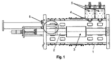
本発明は、高出力マイクロ波発生器に関するものであり、電力合成器/分配器の回路設計に用いられる。無線周波数電力を合成するための装置は、例えば、矩形形状を有する空洞(1)と、比較的大きい半径の中央部分(3)を有する中心円筒形導体(2)と、無線周波数(RF)電力を供給源(5)から前記空洞に入力するための誘導結合要素(4)と、合成された電力を出力するための、前記中心円筒形導体(2)上に固定された可動出力要素(6)とを備えている。この装置は、周波数および位相の高い安定性を提供し、小型の設計である。The present invention relates to a high-power microwave generator and is used for circuit design of a power combiner / distributor. An apparatus for synthesizing radio frequency power includes, for example, a cavity (1) having a rectangular shape, a central cylindrical conductor (2) having a central portion (3) with a relatively large radius, and radio frequency (RF) power. From the source (5) to the cavity and the movable output element (6) fixed on the central cylindrical conductor (2) for outputting the synthesized power. ). This device provides high frequency and phase stability and is a compact design.
Description
技術分野
本発明は、高出力マイクロ波発生器に関するものであり、本発明は、電力合成器/分配器の回路の設計において使用される。
TECHNICAL FIELD The present invention relates to high power microwave generators, which are used in the design of power combiner / distributor circuits.
背景技術
強力なマイクロ波発生器は、現在、単一の高出力増幅器として、または、幾つかの個別の供給源からの電力を合成することに基づいて、という2つの基本的な方式のうちの1つによって構築されている。本出願は、第2の方式の発生器について考える。
BACKGROUND OF THE INVENTION Powerful microwave generators are currently out of two basic schemes, either as a single high power amplifier or based on combining power from several individual sources. Built by one. This application considers a second type of generator.
様々な方式の電力合成器/分配器が当該分野で公知である。従来技術の電力合成器の多くは、電力の合成/分配についての2つの原理で動作する。第1の原理は、同軸ケーブルに実装された異なる伝送線路と、ストリップラインと、異なる種類の伝送線路間の変換のためのバランとを使用することによるものである。Wilkinson方式に基づく、このような電力合成器の例が特許文献1および特許文献2に開示されており、複数の入力端子および1つの出力端子を有する複数の伝送線路と、各入力部からの無線周波数(RF)信号を供給する各接続部を開放/閉鎖するための複数の無線周波数(RF)スイッチとを使用する。例えば、特許文献3および特許文献4に開示されているような、Gysel原理に基づくマルチチャネル電力合成器/分配器は、1つの共通出力/入力ポートと、複数の入力/出力ポートと、各ポートを相互に接続している、対応する複数の第1および第2の伝送線路とを備え、これらは、マイクロストリップ技術によって平面基板上に実装されるか、または、高い電力レベルのための同軸伝送線路と共に実装される。しかしながら、これらの2種類の方式は、伝送される電力レベルに制限があり、通常は、数kWを超えない。 Various types of power combiners / distributors are known in the art. Many prior art power combiners operate on two principles of power combining / distribution. The first principle is by using different transmission lines mounted on the coaxial cable, striplines and baluns for conversion between different types of transmission lines. Examples of such a power combiner based on the Wilkinson method are disclosed in Patent Document 1 and Patent Document 2, and a plurality of transmission lines having a plurality of input terminals and one output terminal, and wireless from each input unit A plurality of radio frequency (RF) switches are used to open / close each connection supplying a frequency (RF) signal. For example, a multi-channel power combiner / distributor based on the Gysel principle as disclosed in Patent Documents 3 and 4 includes one common output / input port, a plurality of input / output ports, and each port. Corresponding first and second transmission lines, which are mounted on a planar substrate by microstrip technology or coaxial transmission for high power levels It is mounted with the track. However, these two types of methods have limitations on the transmitted power level and usually do not exceed a few kW.
電力を合成/分配することについて良く知られている別の原理は、一組の導波管を単一の導波管に接続する原理を用いている、導波管結合器の使用によるものである。この場合、入力部と出力部とが同一の種類の導波管に設けられる(特許文献5、特許文献6)、あるいは、例えば、同軸−導波管変換(特許文献7)もしくは矩形−円形導波管変換(特許文献8)を用いた設計の特定の必要性を考慮に入れて、波の種類の変換部が、入力部と出力部とに設けられる。この種類の電力合成器は、高い電力レベルで動作可能であるが、この種類の電力合成器は、合成される電力供給源の数に対する制限があり、かつ、低無線周波数(RF)帯では大きなサイズを有する。 Another well-known principle for combining and distributing power is through the use of waveguide couplers, which use the principle of connecting a set of waveguides to a single waveguide. is there. In this case, the input unit and the output unit are provided in the same type of waveguide (Patent Document 5, Patent Document 6), or, for example, coaxial-waveguide conversion (Patent Document 7) or rectangular-circular waveguide Taking into account the specific need for design using wave tube conversion (Patent Document 8), wave type conversion units are provided at the input and output units. Although this type of power combiner can operate at high power levels, this type of power combiner has a limit on the number of power sources to be combined and is significant in the low radio frequency (RF) band. Have a size.
本発明の課題は、周波数および位相の高い安定性を保証し、かつ、小さいサイズで低コストという特徴を有する、無線周波数(RF)電力を合成するための装置を提供することにある。 It is an object of the present invention to provide an apparatus for synthesizing radio frequency (RF) power that ensures high frequency and phase stability and has the characteristics of small size and low cost.
上記の課題は、無線周波数(RF)電力を合成するための装置において解決され、この装置には、中心(軸方向)円筒形導体を有する、例えば、矩形断面を有している空洞と、複数の供給源からの無線周波数(RF)電力を前記空洞に入力するための一組の誘導結合要素と、前記合成された電力を出力するための可動出力要素とが備えられている。 The above problems are solved in an apparatus for synthesizing radio frequency (RF) power, which includes a cavity having a central (axial) cylindrical conductor, for example, having a rectangular cross section, and a plurality of A set of inductive coupling elements for inputting radio frequency (RF) power from a plurality of sources into the cavity and a movable output element for outputting the combined power.
前記空洞は円筒形の空洞である、または、前記空洞は多角形の断面を有する。 The cavity is a cylindrical cavity, or the cavity has a polygonal cross section.
前記軸方向円筒形導体は、可変の直径を有し、この軸方向円筒形導体の中央部分は、比較的大きな直径を有する。このことにより、空洞の側壁近傍の磁界の振幅を増加させることが可能になる。 The axial cylindrical conductor has a variable diameter, and the central portion of the axial cylindrical conductor has a relatively large diameter. This makes it possible to increase the amplitude of the magnetic field near the side wall of the cavity.
前記空洞の長さは波長の半分にほぼ等しいが、前記中心導体の半径の変動が発振回路の導電率に寄与するため、前記空洞の長さは変動する。 The cavity length is approximately equal to half the wavelength, but the cavity length varies because variations in the radius of the central conductor contribute to the conductivity of the oscillator circuit.
無線周波数(RF)電力を入力するための(結合ループとして構成された)誘導結合要素は、磁界振幅が最大になる位置に配置される。このような配置は、最良の結合を提供する。 An inductive coupling element (configured as a coupling loop) for inputting radio frequency (RF) power is placed at a position where the magnetic field amplitude is maximized. Such an arrangement provides the best coupling.
空洞の体積体において合成された電力を出力するための可動出力要素は、結合ループとして構成され、軸方向円筒形導体上に固定される。 The movable output element for outputting the synthesized power in the hollow volume is configured as a coupling loop and is fixed on the axial cylindrical conductor.
考えられる1つの実施形態において、本発明に従う、無線周波数(RF)電力を合成する方法は、
中心導体を有する矩形空洞を準備するステップであって、前記中心導体は、前記空洞の長手方向軸に沿って配置される、ステップと、
前記空洞内の磁界振幅が最大になる位置に配置された各誘導結合要素を介して、複数の供給源から前記空洞まで無線周波数(RF)電力を入力するステップと、
前記複数の供給源から入力された無線周波数(RF)電力を、前記空洞内で合成するステップと、
前記合成された無線周波数(RF)電力を、前記空洞から、前記中心導体上に固定された可動結合要素を介して出力するステップと
を含む。
In one possible embodiment, a method of synthesizing radio frequency (RF) power according to the present invention comprises:
Providing a rectangular cavity having a central conductor, the central conductor being disposed along a longitudinal axis of the cavity;
Inputting radio frequency (RF) power from a plurality of sources to the cavity via each inductive coupling element located at a position where the magnetic field amplitude in the cavity is maximized;
Combining radio frequency (RF) power input from the plurality of sources in the cavity;
Outputting the synthesized radio frequency (RF) power from the cavity via a movable coupling element fixed on the central conductor.
本発明は、添付の図面に示された例によって例示される。 The invention is illustrated by the examples shown in the accompanying drawings.
好適な実施形態の説明
図1に示されているように、本発明に従う、無線周波数(RF)電力を合成するための装置は、導波管1と、比較的大きい半径の中央部分3を有する中心(軸方向)円筒形導体2と、供給源5からの無線周波数(RF)電力を入力するための、誘導結合ループとして構成されている要素4と、中心導体2の上に固定された、合成された無線周波数(RF)電力を出力するための可動出力要素6とを備えている。空洞1は、波長の半分にほぼ等しい長さを有する。
DESCRIPTION OF THE PREFERRED EMBODIMENTS As shown in FIG. 1, an apparatus for synthesizing radio frequency (RF) power according to the present invention has a waveguide 1 and a relatively large radius central portion 3. A central (axial) cylindrical conductor 2, an element 4 configured as an inductive coupling loop for inputting radio frequency (RF) power from a source 5, fixed on the central conductor 2, And a movable output element 6 for outputting synthesized radio frequency (RF) power. The cavity 1 has a length approximately equal to half the wavelength.
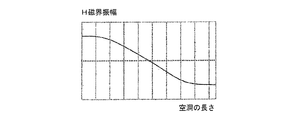
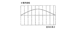
無線周波数(RF)電力合成装置は、以下のように動作する。供給源5からの無線周波数(RF)電力は、誘導無線周波数(RF)電力入力要素4を介して、空洞1に入力される。複数の供給源5から入力された電力は空洞1において合成され、電界分布および磁界分布は、それぞれ、図2aおよび図3aに示されるように設定されている。図2bおよび図3bは、それぞれ、空洞の長さ方向に沿った磁界の振幅および電界の振幅の対応する変化を示している。 The radio frequency (RF) power synthesizer operates as follows. Radio frequency (RF) power from a source 5 is input to the cavity 1 via an inductive radio frequency (RF) power input element 4. The electric power input from the plurality of sources 5 is combined in the cavity 1, and the electric field distribution and magnetic field distribution are set as shown in FIGS. 2a and 3a, respectively. Figures 2b and 3b show the corresponding changes in the amplitude of the magnetic field and of the electric field along the length of the cavity, respectively.
合成された無線周波数(RF)電力は、中心導体2の上に固定された可動の合成無線周波数(RF)電力出力部材6を介して空洞1から出力される。 The combined radio frequency (RF) power is output from the cavity 1 via a movable combined radio frequency (RF) power output member 6 fixed on the center conductor 2.
本発明の電力合成器は、64個までの個別の供給源から電力を合成する。供給源の数は、解決すべき設計タスクに従って選択される。本発明の方式は、周波数および位相に対する高い安定性を提供し、かつ、小さいサイズおよび低コストを特徴とする。 The power combiner of the present invention combines power from up to 64 individual sources. The number of sources is selected according to the design task to be solved. The scheme of the present invention provides high frequency and phase stability and is characterized by small size and low cost.
Claims (6)
中心円筒形導体(2)を有する空洞(1)と、
複数の供給源(5)からの無線周波数(RF)電力を前記空洞(1)に入力するための一組の誘導結合要素(4)と、
前記合成された電力を出力するための、前記中心円筒形導体(2)上に固定された可動出力要素(6)と
を備えている、装置。 An apparatus for synthesizing radio frequency power comprising:
A cavity (1) having a central cylindrical conductor (2);
A set of inductive coupling elements (4) for inputting radio frequency (RF) power from a plurality of sources (5) into the cavity (1);
A movable output element (6) fixed on the central cylindrical conductor (2) for outputting the combined power.
Applications Claiming Priority (3)
| Application Number | Priority Date | Filing Date | Title |
|---|---|---|---|
| RU2013104458A RU2636265C2 (en) | 2013-02-01 | 2013-02-01 | Radio frequency power unifier |
| RU2013104458 | 2013-02-01 | ||
| PCT/RU2014/000067 WO2014120047A1 (en) | 2013-02-01 | 2014-01-28 | Radio frequency power combiner |
Publications (2)
| Publication Number | Publication Date |
|---|---|
| JP2016507191A true JP2016507191A (en) | 2016-03-07 |
| JP2016507191A5 JP2016507191A5 (en) | 2017-06-15 |
Family
ID=50434256
Family Applications (1)
| Application Number | Title | Priority Date | Filing Date |
|---|---|---|---|
| JP2015555957A Pending JP2016507191A (en) | 2013-02-01 | 2014-01-28 | Radio frequency power combiner |
Country Status (7)
| Country | Link |
|---|---|
| US (1) | US20150318600A1 (en) |
| EP (1) | EP2941795A1 (en) |
| JP (1) | JP2016507191A (en) |
| KR (1) | KR20150129684A (en) |
| CN (1) | CN105229848A (en) |
| RU (1) | RU2636265C2 (en) |
| WO (1) | WO2014120047A1 (en) |
Cited By (1)
| Publication number | Priority date | Publication date | Assignee | Title |
|---|---|---|---|---|
| JP2020170905A (en) * | 2019-04-01 | 2020-10-15 | クリオエレクトラ ゲゼルシャフト ミット ベシュレンクテル ハフツングCryoelectra GmbH | High frequency amplification unit with amplification module located on outer conductor |
Families Citing this family (5)
| Publication number | Priority date | Publication date | Assignee | Title |
|---|---|---|---|---|
| US10749239B2 (en) | 2018-09-10 | 2020-08-18 | General Electric Company | Radiofrequency power combiner or divider having a transmission line resonator |
| KR101967426B1 (en) | 2018-09-17 | 2019-05-10 | (주)엑소더스커뮤니케이션스 | Gysel power combiner for high power |
| US10804863B2 (en) | 2018-11-26 | 2020-10-13 | General Electric Company | System and method for amplifying and combining radiofrequency power |
| KR102615963B1 (en) * | 2022-08-02 | 2023-12-20 | 한국핵융합에너지연구원 | Stacked coaxial cavity radio frequency power combiner |
| KR20240018299A (en) * | 2022-08-02 | 2024-02-13 | 한국핵융합에너지연구원 | Radio frequency power amplifier module |
Citations (6)
| Publication number | Priority date | Publication date | Assignee | Title |
|---|---|---|---|---|
| JPS61121506A (en) * | 1984-11-16 | 1986-06-09 | Hitachi Ltd | Microwave solid amplifier |
| JPS63299502A (en) * | 1987-05-29 | 1988-12-07 | Nec Corp | Rotary transmission equipment |
| JPS63300603A (en) * | 1987-05-29 | 1988-12-07 | Fujitsu Ltd | Power distributer/synthesizer |
| JPH01147903A (en) * | 1987-12-04 | 1989-06-09 | Hitachi Ltd | High frequency power synthesizer |
| JPH05235618A (en) * | 1991-05-06 | 1993-09-10 | Hughes Aircraft Co | High-frequency powder divider for flat void |
| JP2000114825A (en) * | 1998-10-02 | 2000-04-21 | Fujitsu Ten Ltd | Antenna power feeder part structure |
Family Cites Families (22)
| Publication number | Priority date | Publication date | Assignee | Title |
|---|---|---|---|---|
| US3156879A (en) * | 1960-07-06 | 1964-11-10 | Gen Electric | Power divider utilizing inductive coupling in a cavity resonator excited in the tm m ode |
| US4188590A (en) * | 1977-11-25 | 1980-02-12 | Hughes Aircraft Company | Conical power combiner |
| US4463326A (en) * | 1980-12-29 | 1984-07-31 | International Telephone And Telegraph Corporation | Planar N-way combiner/divider for microwave circuits |
| JPS59178801A (en) * | 1983-03-29 | 1984-10-11 | Fujitsu Ltd | Resonator type power distribution and combination device |
| US4599584A (en) * | 1984-10-26 | 1986-07-08 | Motorola, Inc. | Power divider/combiner apparatus comprising a fan shaped waveguide |
| US4684874A (en) * | 1985-02-05 | 1987-08-04 | Trw Inc. | Radial wave power divider/combiner and related method |
| SU1764102A1 (en) * | 1989-12-29 | 1992-09-23 | Научно-Производственное Объединение Им.Коминтерна | Signals combining device |
| US5164689A (en) | 1991-04-11 | 1992-11-17 | Harris Corporation | N-way power combiner/divider |
| US5334957A (en) | 1992-11-09 | 1994-08-02 | Harris Corporation | RF high power, two and three way in phase combiner and method |
| US5663693A (en) | 1995-08-31 | 1997-09-02 | Rockwell International | Dielectric waveguide power combiner |
| KR0164368B1 (en) | 1995-10-25 | 1999-02-01 | 김광호 | Rf power combiner |
| US5880648A (en) | 1997-04-21 | 1999-03-09 | Myat, Inc. | N-way RF power combiner/divider |
| US6018280A (en) * | 1998-08-13 | 2000-01-25 | American Microwave Technology Inc. | Broad-band high-power RF combiner |
| US6806791B1 (en) * | 2000-02-29 | 2004-10-19 | Radio Frequency Systems, Inc. | Tunable microwave multiplexer |
| SE520203C2 (en) * | 2000-03-30 | 2003-06-10 | Allgon Ab | A coaxial cavity resonator, filter and use of resonator component in a filter |
| US6411174B1 (en) | 2000-06-14 | 2002-06-25 | Raytheon Company | Compact four-way waveguide power divider |
| JP2002299909A (en) * | 2001-03-30 | 2002-10-11 | Nec Corp | Method for coupling antennas for resonator and coupled antenna |
| US20040041659A1 (en) * | 2002-06-12 | 2004-03-04 | Forem U.S.A. | Compact broadband divider/combiner |
| US7432780B2 (en) | 2005-11-23 | 2008-10-07 | Northrop Grumman Corporation | Rectangular-to-circular mode power combiner/divider |
| US7532089B2 (en) * | 2006-06-06 | 2009-05-12 | Keragis Corporation | Microwave combiner/splitter |
| US8427382B2 (en) | 2010-07-29 | 2013-04-23 | Raytheon Company | Power combiner/divider for coupling N-coaxial input/outputs to a waveguide via a matching plate to provide minimized reflection |
| CN102637933A (en) * | 2012-01-10 | 2012-08-15 | 深圳市大富科技股份有限公司 | Cavity filter and coupling structure of cavity filter |
-
2013
- 2013-02-01 RU RU2013104458A patent/RU2636265C2/en not_active IP Right Cessation
-
2014
- 2014-01-28 US US14/762,178 patent/US20150318600A1/en not_active Abandoned
- 2014-01-28 CN CN201480006978.7A patent/CN105229848A/en active Pending
- 2014-01-28 EP EP14715142.7A patent/EP2941795A1/en not_active Withdrawn
- 2014-01-28 WO PCT/RU2014/000067 patent/WO2014120047A1/en active Application Filing
- 2014-01-28 JP JP2015555957A patent/JP2016507191A/en active Pending
- 2014-01-28 KR KR1020157023075A patent/KR20150129684A/en not_active Application Discontinuation
Patent Citations (6)
| Publication number | Priority date | Publication date | Assignee | Title |
|---|---|---|---|---|
| JPS61121506A (en) * | 1984-11-16 | 1986-06-09 | Hitachi Ltd | Microwave solid amplifier |
| JPS63299502A (en) * | 1987-05-29 | 1988-12-07 | Nec Corp | Rotary transmission equipment |
| JPS63300603A (en) * | 1987-05-29 | 1988-12-07 | Fujitsu Ltd | Power distributer/synthesizer |
| JPH01147903A (en) * | 1987-12-04 | 1989-06-09 | Hitachi Ltd | High frequency power synthesizer |
| JPH05235618A (en) * | 1991-05-06 | 1993-09-10 | Hughes Aircraft Co | High-frequency powder divider for flat void |
| JP2000114825A (en) * | 1998-10-02 | 2000-04-21 | Fujitsu Ten Ltd | Antenna power feeder part structure |
Cited By (2)
| Publication number | Priority date | Publication date | Assignee | Title |
|---|---|---|---|---|
| JP2020170905A (en) * | 2019-04-01 | 2020-10-15 | クリオエレクトラ ゲゼルシャフト ミット ベシュレンクテル ハフツングCryoelectra GmbH | High frequency amplification unit with amplification module located on outer conductor |
| JP2022044584A (en) * | 2019-04-01 | 2022-03-17 | クリオエレクトラ ゲゼルシャフト ミット ベシュレンクテル ハフツング | High frequency amplification unit with amplification module placed on outer conductor |
Also Published As
| Publication number | Publication date |
|---|---|
| CN105229848A (en) | 2016-01-06 |
| RU2636265C2 (en) | 2017-11-21 |
| US20150318600A1 (en) | 2015-11-05 |
| RU2013104458A (en) | 2014-08-10 |
| EP2941795A1 (en) | 2015-11-11 |
| WO2014120047A1 (en) | 2014-08-07 |
| KR20150129684A (en) | 2015-11-20 |
Similar Documents
| Publication | Publication Date | Title |
|---|---|---|
| JP2016507191A (en) | Radio frequency power combiner | |
| EP2281321B1 (en) | Power splitter | |
| CN104662733B (en) | Serve as the RF power combiners of high-order harmonic wave wave filter | |
| JPWO2015037033A1 (en) | Power amplifier and transmitter | |
| Li Shen et al. | Dual‐band balun with flexible frequency ratios | |
| JPWO2008062754A1 (en) | Planar configuration microwave signal multi-distributor | |
| JP2007157535A5 (en) | ||
| Wu et al. | Generalized high‐isolation n‐way Gysel power divider with arbitrary power ratio and different real terminated impedances | |
| CN110707438A (en) | Ka-band low-consumption compact feed network | |
| KR101713769B1 (en) | Spatial power combiner based on coaxial waveguide | |
| JP4757942B2 (en) | Broadband hybrid coupler and related method | |
| Schulz et al. | A broadband circular TE 11-to TE 01-mode converter using stepped waveguide technique | |
| US10381705B2 (en) | Radial power combiner/divider using dielectrically loaded waveguides | |
| US11405012B2 (en) | Balun and method for manufacturing the same | |
| CN103081222A (en) | N port feeding system having distribution structure and feeding element included therein | |
| JP4903100B2 (en) | Waveguide power combiner / distributor and array antenna device using the same | |
| JP6776839B2 (en) | Amplifier and transmitter | |
| JP2013236349A (en) | Power divider/combiner | |
| Oborzhytskyy et al. | Design of dual-frequency TEM-mode coupled-line directional couplers | |
| TW201840127A (en) | Multi-way power amplifying circuit capable of reducing power consumption and replacing traditional power splitter to save area | |
| RU182106U1 (en) | COMPACT RING BRIDGE | |
| WO2014147823A1 (en) | Power amplification device and communications device | |
| JP6000120B2 (en) | High frequency transmission line | |
| JP2022044584A (en) | High frequency amplification unit with amplification module placed on outer conductor | |
| WO2014035274A1 (en) | Odd harmonic radial rf filter |
Legal Events
| Date | Code | Title | Description |
|---|---|---|---|
| A131 | Notification of reasons for refusal |
Free format text: JAPANESE INTERMEDIATE CODE: A131 Effective date: 20160620 |
|
| A601 | Written request for extension of time |
Free format text: JAPANESE INTERMEDIATE CODE: A601 Effective date: 20160920 |
|
| A521 | Request for written amendment filed |
Free format text: JAPANESE INTERMEDIATE CODE: A523 Effective date: 20161118 |
|
| A02 | Decision of refusal |
Free format text: JAPANESE INTERMEDIATE CODE: A02 Effective date: 20161220 |
|
| A711 | Notification of change in applicant |
Free format text: JAPANESE INTERMEDIATE CODE: A712 Effective date: 20161222 |
|
| A524 | Written submission of copy of amendment under article 19 pct |
Free format text: JAPANESE INTERMEDIATE CODE: A524 Effective date: 20170420 |
|
| A911 | Transfer to examiner for re-examination before appeal (zenchi) |
Free format text: JAPANESE INTERMEDIATE CODE: A911 Effective date: 20170427 |
|
| A912 | Re-examination (zenchi) completed and case transferred to appeal board |
Free format text: JAPANESE INTERMEDIATE CODE: A912 Effective date: 20170623 |
|
| A601 | Written request for extension of time |
Free format text: JAPANESE INTERMEDIATE CODE: A601 Effective date: 20180515 |