JP2016216801A - Three-dimensional forming apparatus and three-dimensional forming method - Google Patents
Three-dimensional forming apparatus and three-dimensional forming method Download PDFInfo
- Publication number
- JP2016216801A JP2016216801A JP2015106177A JP2015106177A JP2016216801A JP 2016216801 A JP2016216801 A JP 2016216801A JP 2015106177 A JP2015106177 A JP 2015106177A JP 2015106177 A JP2015106177 A JP 2015106177A JP 2016216801 A JP2016216801 A JP 2016216801A
- Authority
- JP
- Japan
- Prior art keywords
- sintered
- dimensional
- stage
- unit
- single layer
- Prior art date
- Legal status (The legal status is an assumption and is not a legal conclusion. Google has not performed a legal analysis and makes no representation as to the accuracy of the status listed.)
- Pending
Links
Images


Classifications
-
- B—PERFORMING OPERATIONS; TRANSPORTING
- B22—CASTING; POWDER METALLURGY
- B22F—WORKING METALLIC POWDER; MANUFACTURE OF ARTICLES FROM METALLIC POWDER; MAKING METALLIC POWDER; APPARATUS OR DEVICES SPECIALLY ADAPTED FOR METALLIC POWDER
- B22F10/00—Additive manufacturing of workpieces or articles from metallic powder
-
- B—PERFORMING OPERATIONS; TRANSPORTING
- B29—WORKING OF PLASTICS; WORKING OF SUBSTANCES IN A PLASTIC STATE IN GENERAL
- B29C—SHAPING OR JOINING OF PLASTICS; SHAPING OF MATERIAL IN A PLASTIC STATE, NOT OTHERWISE PROVIDED FOR; AFTER-TREATMENT OF THE SHAPED PRODUCTS, e.g. REPAIRING
- B29C64/00—Additive manufacturing, i.e. manufacturing of three-dimensional [3D] objects by additive deposition, additive agglomeration or additive layering, e.g. by 3D printing, stereolithography or selective laser sintering
- B29C64/10—Processes of additive manufacturing
- B29C64/165—Processes of additive manufacturing using a combination of solid and fluid materials, e.g. a powder selectively bound by a liquid binder, catalyst, inhibitor or energy absorber
-
- B—PERFORMING OPERATIONS; TRANSPORTING
- B22—CASTING; POWDER METALLURGY
- B22F—WORKING METALLIC POWDER; MANUFACTURE OF ARTICLES FROM METALLIC POWDER; MAKING METALLIC POWDER; APPARATUS OR DEVICES SPECIALLY ADAPTED FOR METALLIC POWDER
- B22F10/00—Additive manufacturing of workpieces or articles from metallic powder
- B22F10/10—Formation of a green body
- B22F10/16—Formation of a green body by embedding the binder within the powder bed
-
- B—PERFORMING OPERATIONS; TRANSPORTING
- B22—CASTING; POWDER METALLURGY
- B22F—WORKING METALLIC POWDER; MANUFACTURE OF ARTICLES FROM METALLIC POWDER; MAKING METALLIC POWDER; APPARATUS OR DEVICES SPECIALLY ADAPTED FOR METALLIC POWDER
- B22F12/00—Apparatus or devices specially adapted for additive manufacturing; Auxiliary means for additive manufacturing; Combinations of additive manufacturing apparatus or devices with other processing apparatus or devices
- B22F12/22—Driving means
-
- B—PERFORMING OPERATIONS; TRANSPORTING
- B22—CASTING; POWDER METALLURGY
- B22F—WORKING METALLIC POWDER; MANUFACTURE OF ARTICLES FROM METALLIC POWDER; MAKING METALLIC POWDER; APPARATUS OR DEVICES SPECIALLY ADAPTED FOR METALLIC POWDER
- B22F3/00—Manufacture of workpieces or articles from metallic powder characterised by the manner of compacting or sintering; Apparatus specially adapted therefor ; Presses and furnaces
- B22F3/003—Apparatus, e.g. furnaces
-
- B—PERFORMING OPERATIONS; TRANSPORTING
- B33—ADDITIVE MANUFACTURING TECHNOLOGY
- B33Y—ADDITIVE MANUFACTURING, i.e. MANUFACTURING OF THREE-DIMENSIONAL [3-D] OBJECTS BY ADDITIVE DEPOSITION, ADDITIVE AGGLOMERATION OR ADDITIVE LAYERING, e.g. BY 3-D PRINTING, STEREOLITHOGRAPHY OR SELECTIVE LASER SINTERING
- B33Y30/00—Apparatus for additive manufacturing; Details thereof or accessories therefor
-
- B—PERFORMING OPERATIONS; TRANSPORTING
- B33—ADDITIVE MANUFACTURING TECHNOLOGY
- B33Y—ADDITIVE MANUFACTURING, i.e. MANUFACTURING OF THREE-DIMENSIONAL [3-D] OBJECTS BY ADDITIVE DEPOSITION, ADDITIVE AGGLOMERATION OR ADDITIVE LAYERING, e.g. BY 3-D PRINTING, STEREOLITHOGRAPHY OR SELECTIVE LASER SINTERING
- B33Y10/00—Processes of additive manufacturing
-
- Y—GENERAL TAGGING OF NEW TECHNOLOGICAL DEVELOPMENTS; GENERAL TAGGING OF CROSS-SECTIONAL TECHNOLOGIES SPANNING OVER SEVERAL SECTIONS OF THE IPC; TECHNICAL SUBJECTS COVERED BY FORMER USPC CROSS-REFERENCE ART COLLECTIONS [XRACs] AND DIGESTS
- Y02—TECHNOLOGIES OR APPLICATIONS FOR MITIGATION OR ADAPTATION AGAINST CLIMATE CHANGE
- Y02P—CLIMATE CHANGE MITIGATION TECHNOLOGIES IN THE PRODUCTION OR PROCESSING OF GOODS
- Y02P10/00—Technologies related to metal processing
- Y02P10/25—Process efficiency
Landscapes
- Engineering & Computer Science (AREA)
- Chemical & Material Sciences (AREA)
- Materials Engineering (AREA)
- Manufacturing & Machinery (AREA)
- Mechanical Engineering (AREA)
- Physics & Mathematics (AREA)
- Optics & Photonics (AREA)
- Powder Metallurgy (AREA)
Abstract
Description
本発明は、3次元形成装置および3次元形成方法に関する。 The present invention relates to a three-dimensional forming apparatus and a three-dimensional forming method.
従来、金属材料を用いて3次元形状を簡便に形成する製造方法として、特許文献1に示すような方法が開示されている。特許文献1に開示されている3次元形状造形物の製造方法は、原料に金属粉末と、溶剤と、粘着増進剤と、を有する金属ペーストを層状の材料層に形成して用いる。そして、層状の材料層に光ビームを照射して金属の焼結層もしくは金属の溶融層を形成し、材料層の形成と、光ビームの照射と、を繰り返すことにより焼結層もしくは溶融層が積層され、所望の3次元形状造形物が得られる。
Conventionally, a method as disclosed in
また、特許文献2に開示されている肉盛(3次元)形成が可能な粉末金属肉盛ノズル、あるいは特許文献3に開示されている肉盛溶接が可能なパウダ供給ノズル、を用いることで、金属粉末の供給と、供給された金属粉末をレーザーによって溶融、凝固させて3次元形状造形物が形成されることが示唆されている。
In addition, by using a powder metal overlay nozzle capable of overlaying (three-dimensional) formation disclosed in
特許文献1に開示された方法のように材料層に焼結層を形成し、積層することで3次元形状造形物を得たり、特許文献2,3に開示された方法のように肉盛りを繰り返すことで3次元形状造形物が形成可能であったり、する。いずれの方法も3次元形状造形物を構成する一つの単層を形成し、積層するものである。この単層を形成する場合、3次元形状造形物における1構成の単層の成形では、特許文献1の場合には成形される焼結部の形状を埋めるような軌跡を描いてレーザー照射の走査が行われ、特許文献2,3の場合には焼結部の形状を埋めるような軌跡に沿ってノズル移動が行われる。すなわち、3次元形状造形物を形成するテーブルと、レーザー照射装置、あるいはノズルと、を相対的に移動させて上述の軌跡を描かせるために、相対的な移動をさせる装置駆動部には細かな制御が必要となる。
A sintered layer is formed on the material layer as in the method disclosed in
また、上述の単層の形成時間が、軌跡の長さが長くなる、すなわち焼結部の面積が大きくなることで長くなる。従って、生産性を高めるには、レーザー照射の走査速度、あるいはノズルの移動速度を高める必要があったが、レーザーの出力も高めないと、焼結不良、溶融不良を発生する虞があった。 Further, the formation time of the above-mentioned single layer becomes longer as the length of the trajectory becomes longer, that is, the area of the sintered part becomes larger. Therefore, in order to increase the productivity, it is necessary to increase the scanning speed of laser irradiation or the moving speed of the nozzle. However, if the output of the laser is not increased, there is a possibility of causing poor sintering and poor melting.
そこで、複数のエネルギー供給手段を、簡単な構成で同期させて駆動することで、高い生産性を持った3次元形成装置を得ることを目的とする。 Accordingly, it is an object of the present invention to obtain a three-dimensional forming apparatus having high productivity by driving a plurality of energy supply means synchronously with a simple configuration.
本発明は、上述の課題の少なくとも一部を解決するためになされたものであり、以下の形態または適用例として実現することが可能である。 SUMMARY An advantage of some aspects of the invention is to solve at least a part of the problems described above, and the invention can be implemented as the following forms or application examples.
〔適用例1〕本適用例の3次元形成装置は、ステージと、金属粉末と、バインダーと、が混練された被焼結材料を前記ステージに供給する材料供給手段と、前記材料供給手段により供給された前記被焼結材料に、前記被焼結材料を焼結可能とするエネルギーを供給するエネルギー照射部を備えるヘッドユニットと、前記ヘッドユニットを複数保持するヘッドベースと、を備え、前記ステージに対して、前記ヘッドベースが、相対的に3次元移動が可能となる駆動手段を備えることを特徴とする。 [Application Example 1] A three-dimensional forming apparatus according to this application example is provided with a material supply means for supplying a material to be sintered in which a stage, a metal powder, and a binder are kneaded to the stage, and the material supply means. A head unit that includes an energy irradiation unit that supplies energy to enable sintering of the material to be sintered, and a head base that holds a plurality of the head units. On the other hand, the head base includes a driving unit that can relatively move three-dimensionally.
ヘッドベースをステージに対する相対的な移動の1経路に沿って、一つのヘッドユニットに備えるエネルギー照射部から照射されるエネルギーによって、一つのエネルギー照射部の対応した焼結部が形成される。そこで、本適用例の3次元形成装置によれば、ヘッドベースに複数のヘッドユニットを備えていることで、ヘッドベースの1経路に沿って複数の焼結部を形成することができる。従って、所望の焼結領域を形成するためのヘッドベースと、ステージと、の相対移動経路長を短くすることができ、高い生産性を備える3次元形成装置を得ることができる。 A corresponding sintered part of one energy irradiation part is formed by energy irradiated from an energy irradiation part provided in one head unit along one path of relative movement of the head base with respect to the stage. Therefore, according to the three-dimensional forming apparatus of this application example, since the head base includes a plurality of head units, a plurality of sintered portions can be formed along one path of the head base. Therefore, the relative movement path length between the head base for forming a desired sintered region and the stage can be shortened, and a three-dimensional forming apparatus having high productivity can be obtained.
〔適用例2〕本適用例の3次元形成装置は、ステージと、金属粉末と、バインダーと、が混練された被焼結材料を前記ステージに供給する材料吐出部を備える材料供給手段と、前記材料供給手段により供給された前記被焼結材料に、前記被焼結材料を焼結可能とするエネルギーを供給するエネルギー照射部と、を備え、前記材料吐出部と、前記エネルギー照射部と、が保持されたヘッドユニットを複数保持するヘッドベースを備え、前記ステージに対して、前記ヘッドベースが、相対的に3次元移動が可能となる駆動手段を備えることを特徴とする。 Application Example 2 A three-dimensional forming apparatus according to this application example includes a material supply unit including a material discharge unit that supplies a material to be sintered, in which a stage, a metal powder, and a binder are kneaded, to the stage; An energy irradiation unit that supplies energy to enable the sintering of the material to be sintered to the material to be sintered supplied by the material supply unit, and the material discharge unit and the energy irradiation unit include: A head base for holding a plurality of held head units is provided, and the head base is provided with a driving unit that can relatively move three-dimensionally with respect to the stage.
ヘッドベースをステージに対する相対的な移動の1経路に沿って、一つのヘッドユニットに備える材料吐出部から供給される被焼結材料にエネルギー照射部から照射されるエネルギーによって、一つのヘッドユニットに対応した焼結部が形成される。そこで、本適用例の3次元形成装置によれば、ヘッドベースに複数のヘッドユニットを備えていることで、ヘッドベースの1経路に沿って複数の焼結部を形成することができる。従って、所望の焼結領域を形成するためのヘッドベースと、ステージと、の相対移動経路長を短くすることができ、高い生産性を備える3次元形成装置を得ることができる。 Corresponding to one head unit by the energy irradiated from the energy irradiation part to the material to be sintered supplied from the material discharge part of one head unit along one path of relative movement of the head base with respect to the stage The sintered part is formed. Therefore, according to the three-dimensional forming apparatus of this application example, since the head base includes a plurality of head units, a plurality of sintered portions can be formed along one path of the head base. Therefore, the relative movement path length between the head base for forming a desired sintered region and the stage can be shortened, and a three-dimensional forming apparatus having high productivity can be obtained.
また、本適用例の3次元形成装置によれば、形成される3次元形状造形物の形状を形成する領域に必要な量の被焼結材料が供給され、供給された被焼結材料に向けてエネルギー照射部からエネルギーが供給されるため、材料供給のロス、供給エネルギーのロスが削減される。 Further, according to the three-dimensional forming apparatus of this application example, a necessary amount of the material to be sintered is supplied to the region for forming the shape of the three-dimensional shaped object to be formed, and directed toward the supplied material to be sintered. Since energy is supplied from the energy irradiation unit, material supply loss and supply energy loss are reduced.
〔適用例3〕上述の適用例において、複数備える前記材料供給手段の内、少なくとも1つの前記ヘッドユニットに保持される前記材料吐出部を含む前記材料供給手段と、他の前記材料供給手段と、は、収容される前記被焼結材料が異なることを特徴とする。 Application Example 3 In the application example described above, the material supply unit including the material discharge unit held by at least one of the plurality of material supply units, and the other material supply unit. Is characterized in that the sintered material to be accommodated is different.
上述の適用例によれば、異なる組成毎に被焼結材料を供給する材料供給手段を備えることができ、組成毎の各材料供給手段の材料供給と、エネルギー照射部と、によって異なる材料の焼結もしくは熔融を可能とし、2種以上の組成材料からなる造形物を容易に形成することができる。 According to the application example described above, the material supply means for supplying the material to be sintered for each different composition can be provided, and different materials are fired depending on the material supply of each material supply means for each composition and the energy irradiation unit. Bonding or melting is possible, and a shaped article made of two or more kinds of composition materials can be easily formed.
〔適用例4〕上述の適用例において、前記エネルギーがレーザーであることを特徴とする。 Application Example 4 In the application example described above, the energy is a laser.
上述の適用例によれば、ターゲットとなる供給材料に集中してエネルギーを照射することができ、品質の良い3次元形状造形物を形成することができる。また、例えば被焼結材料の種類に合わせて、照射エネルギー量(パワー、走査速度)を制御することが容易に行うことができ、所望の品質の3次元形状造形物を得ることができる。 According to the application example described above, energy can be applied to the target supply material in a concentrated manner, and a high-quality three-dimensional shaped object can be formed. Further, for example, it is possible to easily control the amount of irradiation energy (power, scanning speed) according to the kind of the material to be sintered, and a three-dimensional shaped object with a desired quality can be obtained.
〔適用例5〕本適用例の3次元形成方法は、金属粉末と、バインダーと、が混練された被焼結材料をステージに供給する材料供給工程と、前記被焼結材料を焼結可能とするエネルギーを供給するエネルギー照射部を備えるヘッドユニットを複数保持するヘッドベースを、前記ステージに対して相対的に移動させ、前記エネルギーを前記被焼結材料に向けて供給し、前記被焼結材料を焼結させる焼結工程と、により単層を形成する単層形成工程と、前記単層形成工程によって形成された第一の単層に積層させ、前記単層形成工程によって第二の単層を形成する積層工程と、を含み、前記積層工程を所定の回数、繰り返すことを特徴とする。 [Application Example 5] The three-dimensional forming method of this application example includes a material supplying step of supplying a material to be sintered in which metal powder and a binder are kneaded to a stage, and the material to be sintered can be sintered. A head base that holds a plurality of head units each having an energy irradiation unit that supplies energy to be moved, is moved relative to the stage, and the energy is supplied toward the material to be sintered; A single layer forming step for forming a single layer by laminating the first single layer formed by the single layer forming step, and a second single layer by the single layer forming step. And laminating step, and repeating the laminating step a predetermined number of times.
ヘッドベースをステージに対する相対的な移動の1経路に沿って、一つのヘッドユニットに備えるエネルギー照射部から照射されるエネルギーによって、一つのエネルギー照射部の対応した焼結部が形成される。そこで、本適用例の3次元形成方法によれば、ヘッドベースに複数のヘッドユニットを備える3次元形成装置を用いることで、ヘッドベースの1経路に沿って複数の焼結部を形成することができる。従って、所望の焼結領域を形成するためのヘッドベースと、ステージと、の相対移動経路長を短くすることができ、高い生産性を実現する3次元形成方法を得ることができる。 A corresponding sintered part of one energy irradiation part is formed by energy irradiated from an energy irradiation part provided in one head unit along one path of relative movement of the head base with respect to the stage. Therefore, according to the three-dimensional forming method of this application example, a plurality of sintered portions can be formed along one path of the head base by using a three-dimensional forming apparatus including a plurality of head units in the head base. it can. Therefore, the relative movement path length between the head base for forming a desired sintered region and the stage can be shortened, and a three-dimensional forming method that realizes high productivity can be obtained.
なお、本適用例における「第一の単層」および「第二の単層」とは、繰り返して積層される単層の、積層下部の単層を「第一の単層」、第一の単層上に積層される単層を「第二の単層」と呼び、積層される単層の1層目あるいは2層目を示すものではない。 Note that the “first single layer” and the “second single layer” in this application example are single layers that are repeatedly stacked, the single layer at the bottom of the stack being the “first single layer”, the first layer A single layer stacked on the single layer is referred to as a “second single layer” and does not indicate the first layer or the second layer of the stacked single layers.
〔適用例6〕本適用例の3次元形成方法は、金属粉末と、バインダーと、が混練された被焼結材料をステージに供給する材料供給手段に備える材料吐出部と、前記材料供給手段により供給された前記被焼結材料に、前記被焼結材料を焼結可能とするエネルギーを供給するエネルギー照射部と、が保持されたヘッドユニットを複数保持するヘッドベースを、前記ステージに対して、相対的に移動させ、前記材料吐出部から前記ステージに前記被焼結材料を吐出する材料供給工程と、前記材料供給工程によって吐出された前記被焼結材料に向けて前記エネルギーを供給し、前記被焼結材料を焼結させる焼結工程と、を含む 単層を形成する単層形成工程と、前記単層形成工程によって形成された第一の単層に積層させ、前記単層形成工程によって第二の単層を形成する積層工程と、を含み、前記積層工程を所定の回数、繰り返すことを特徴とする。 Application Example 6 The three-dimensional forming method of this application example includes a material discharge unit provided in a material supply means for supplying a material to be sintered in which metal powder and a binder are kneaded to the stage, and the material supply means. An energy irradiation unit that supplies energy to enable sintering of the material to be sintered to the supplied material to be sintered, and a head base that holds a plurality of head units that are held, with respect to the stage, A material supply step of discharging the material to be sintered from the material discharge unit to the stage; and supplying the energy toward the material to be sintered discharged by the material supply step; A sintering step for sintering the material to be sintered, a single layer forming step for forming a single layer, a first single layer formed by the single layer forming step, and a single layer forming step. First A lamination step of forming two single layers, wherein the lamination step is repeated a predetermined number of times.
ヘッドベースをステージに対する相対的な移動の1経路に沿って、一つのヘッドユニットに備える材料吐出部から供給される被焼結材料にエネルギー照射部から照射されるエネルギーによって、一つのヘッドユニットに対応した焼結部が形成される。そこで、本適用例の3次元形成方法によれば、ヘッドベースに複数のヘッドユニットを備える3次元形成装置を用いることで、ヘッドベースの1経路に沿って複数の焼結部を形成することができる。従って、所望の焼結領域を形成するためのヘッドベースと、ステージと、の相対移動経路長を短くすることができ、高い生産性を実現する3次元形成方法を得ることができる。 Corresponding to one head unit by the energy irradiated from the energy irradiation part to the material to be sintered supplied from the material discharge part of one head unit along one path of relative movement of the head base with respect to the stage The sintered part is formed. Therefore, according to the three-dimensional forming method of this application example, a plurality of sintered portions can be formed along one path of the head base by using a three-dimensional forming apparatus including a plurality of head units in the head base. it can. Therefore, the relative movement path length between the head base for forming a desired sintered region and the stage can be shortened, and a three-dimensional forming method that realizes high productivity can be obtained.
なお、本適用例における「第一の単層」および「第二の単層」とは、繰り返して積層される単層の、積層下部の単層を「第一の単層」、第一の単層上に積層される単層を「第二の単層」と呼び、積層される単層の1層目あるいは2層目を示すものではない。 Note that the “first single layer” and the “second single layer” in this application example are single layers that are repeatedly stacked, the single layer at the bottom of the stack being the “first single layer”, the first layer A single layer stacked on the single layer is referred to as a “second single layer” and does not indicate the first layer or the second layer of the stacked single layers.
〔適用例7〕上述の適用例において、複数備える前記材料供給手段の内、少なくとも1つの前記ヘッドユニットに保持される前記材料吐出部を含む前記材料供給手段と、他の前記材料供給手段と、は、収容される前記被焼結材料が異なることを特徴とする。 Application Example 7 In the application example described above, the material supply unit including the material discharge unit held by at least one of the plurality of material supply units, the other material supply unit, Is characterized in that the sintered material to be accommodated is different.
上述の適用例によれば、異なる組成毎に被焼結材料を供給する材料供給手段を備えることができ、組成毎の各材料供給手段の材料供給と、エネルギー照射部と、によって異なる材料の焼結もしくは熔融を可能とし、2種以上の組成材料からなる造形物を容易に形成することができる。 According to the application example described above, the material supply means for supplying the material to be sintered for each different composition can be provided, and different materials are fired depending on the material supply of each material supply means for each composition and the energy irradiation unit. Bonding or melting is possible, and a shaped article made of two or more kinds of composition materials can be easily formed.
〔適用例8〕上述の適用例において、前記エネルギーがレーザーであることを特徴とする。 Application Example 8 In the application example described above, the energy is a laser.
上述の適用例によれば、ターゲットとなる供給材料に集中してエネルギーを照射することができ、品質の良い3次元形状造形物を形成することができる。また、例えば被焼結材料の種類に合わせて、照射エネルギー量(パワー、走査速度)を制御することが容易に行うことができ、所望の品質の3次元形状造形物を得ることができる。 According to the application example described above, energy can be applied to the target supply material in a concentrated manner, and a high-quality three-dimensional shaped object can be formed. Further, for example, it is possible to easily control the amount of irradiation energy (power, scanning speed) according to the kind of the material to be sintered, and a three-dimensional shaped object with a desired quality can be obtained.
以下、図面を参照して、本発明に係る実施形態を説明する。 Embodiments according to the present invention will be described below with reference to the drawings.
(第1実施形態)
図1は第1実施形態に係る3次元形成装置の構成を示す概略構成図である。なお、本明細書における「3次元形成」とは、いわゆる立体造形物を形成することを示すものであって、例えば、平板状、いわゆる2次元形状の形状であっても厚みを有する形状を形成することも含まれる。
(First embodiment)
FIG. 1 is a schematic configuration diagram showing the configuration of the three-dimensional forming apparatus according to the first embodiment. In addition, “three-dimensional formation” in this specification means forming a so-called three-dimensional modeled object. For example, a flat shape, that is, a so-called two-dimensional shape is formed with a thickness. To include.
図1に示す3次元形成装置1000(以下、形成装置1000という)は、3次元形状造形物を形成する焼結装置100と、3次元形状造形物の原料となる金属粉末とバインダーを混練し、シート状に成形した、いわゆるグリーンシートと呼ばれる供給材料300(以下、グリーンシート300という)を焼結装置100に供給する材料供給手段としての材料供給装置200と、を備えている。
A three-dimensional forming apparatus 1000 (hereinafter referred to as a forming apparatus 1000) shown in FIG. 1 kneads a
材料供給装置200は、供給基台210と、供給基台210に備える図示しない駆動手段によって、図示する重力方向に沿うZ軸方向に駆動可能に備えられた供給テーブル220と、供給テーブル220に載置され、最上に積載された複数のグリーンシート300の1枚を保持し焼結装置100へ移送する移送装置230と、を備えている。
The
移送装置230は、グリーンシート300が保持可能なシート保持部230aと、シート保持部230aを供給テーブル220に対して相対的に少なくともX軸およびY軸方向に移動させる供給駆動部230bと、を備えている。シート保持部230aには、例えば減圧吸盤等のグリーンシート300を保持および離脱可能とする手段のシート吸着部230cを備え、シート吸着部230cによってグリーンシート300を吸着、保持することができる。なお、シート吸着部230cのグリーンシート300の保持方法は、上述に限定されず、例えば、原料金属が磁性体であれば磁力吸着等の方法、あるいはパイロットホールを利用して機械的に保持してもよい。
The
焼結装置100は、基台110と、基台110に備える駆動手段としての駆動装置111によって、図示するX,Y,Z方向への移動、あるいはZ軸を中心とした回転方向に駆動可能に備えられたステージ120と、一方の端部が基台110に固定され、他方の端部にエネルギー照射部140を複数保持するヘッドベース150が保持固定されるヘッドベース支持部130と、を備えている。なお、本実施形態ではステージ120を駆動装置111によってX、Y,Z方向に駆動させる構成を説明するが、これに限定されず、ステージ120と、ヘッドベース150と、が相対的にX,Y,Z方向に駆動可能であればよい。
The
ステージ120上には後述するエネルギー照射部から照射される熱エネルギーからステージ120を保護する、耐熱性を有する試料プレート121と、を備えている。そして、試料プレート121の上に、材料供給装置200から移送されたグリーンシート300が積層配置される。なお、最上層に移送されて積層されるグリーンシート300に対して、直下層のグリーンシート300を密着させるため、最上層のグリーンシート300上を押圧しながら本例ではX軸方向に往復駆動させるプレスローラー170を備えていてもよい。また、プレスローラー170は、上下のグリーンシート300間の密着性を向上させるため、グリーンシート300を加熱する手段を備えていることが好ましい。
On the
ヘッドベース150に保持される複数のエネルギー照射部140は、本実施形態ではエネルギーとしてレーザーを照射するエネルギー照射部140により説明する(以下、エネルギー照射部140をレーザー照射部140という)。照射されるエネルギーにレーザーを用いることにより、ターゲットとなる供給材料に集中してエネルギーを照射することができ、品質の良い3次元形状造形物を形成することができる。また、例えば被焼結材料の種類に合わせて、照射エネルギー量(パワー、走査速度)を制御することが容易に行うことができ、所望の品質の3次元形状造形物を得ることができる。
The plurality of
形成装置1000には、図示しない、例えばパーソナルコンピューター等のデータ出力装置から出力される3次元形状造形物の造形用データに基づいて、上述したステージ120、供給テーブル220、レーザー照射部140、および移送装置230を制御する制御手段としての制御ユニット400を備えている。制御ユニット400には、図示しないが、ステージ120の駆動制御部、供給テーブル220の駆動制御部、レーザー照射部140の駆動制御部、および移送装置230の駆動制御部を備え、それらを連携させて駆動するように制御する制御部と、を備えている。
The forming
基台110に備える駆動装置111によって、基台110に対して移動可能に備えられているステージ120、および供給基台210に移動可能に備えられている供給テーブル220は、制御ユニット400からの制御信号に基づき、ステージコントローラー410においてステージ120、あるいは供給テーブル220の移動開始と停止、移動方向、移動量、移動速度などを制御する信号が生成され、基台110に備える駆動装置111、あるいは供給基台210に備える図示されない駆動装置に送られ、駆動される。
The
材料供給装置200に備える移送装置230は、制御ユニット400からの制御信号に基づき、材料供給装置コントローラー420において、移送装置230に備える供給駆動部230bによるシート保持部230aの移動、およびシート吸着部230cへのグリーンシート300の保持あるいは離脱、などを制御する信号が生成され、グリーンシート300の焼結装置100への移送が制御される。
Based on the control signal from the
ヘッドベース150に保持されるレーザー照射部140は、制御ユニット400から制御信号がレーザーコントローラー430に送られ、レーザーコントローラー430から、複数のレーザー照射部140のいずれか、またはすべてにレーザーを照射させる出力信号が送られる。なお、レーザー照射部140からのレーザー照射は、ステージコントローラー410によるステージ120の駆動信号と同期して、ステージ120上に載置されたグリーンシート300に対して、所定の3次元形状造形物の形状データから得られた焼結形成領域に照射されるように制御される。
The
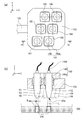
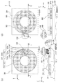
図2は、ヘッドベース150に複数保持されるヘッドユニット160に備えるレーザー照射部140の、保持形態の一例を示し、図2(a)は図1に示す矢印A方向からのヘッドベース150の外観図、図2(b)は図2(a)に示すB−B´部の概略断面図である。
FIG. 2 shows an example of a holding form of the
図2(a)に示すように、第1実施形態に係る形成装置1000に備えるヘッドベース150には、複数のヘッドユニット160が保持されている。ヘッドユニット160は、図2(b)に示すように、レーザー照射部140と、レーザー照射部140のレーザーLを出射するレーザー出射口140aが、グリーンシート300に向けてヘッドベース150に配設されるようにレーザー照射部140を保持する保持治具160aと、を備えている。そしてヘッドユニット160は、図示しない着脱可能な固着手段によってヘッドベース150に固定される。
As shown in FIG. 2A, a plurality of
本実施形態ではヘッドユニット160が6セット、ヘッドベース150に固着されている。その配列は、図2(a)に示すように、図表示の下側より第1列目のヘッドユニット161,162、第2列目のヘッドユニット163,164、そして第3列目のヘッドユニット165,166の1列2セット、3列の配置がされている。そして、図2(b)に示すように、レーザー照射部140から照射されるレーザーLによってグリーンシート300に、焼結幅rを有する焼結部310が形成され、ヘッドベース150に保持された複数のヘッドユニット161,162,163,164,165,166に備えるレーザー照射部140から照射されるレーザーLによって形成される焼結部310の集合体として、3次元形状造形物の構成の一部が形成される。
In this embodiment, six sets of
図3は、ヘッドユニット160の配置と、焼結部310の形成形態と、の関係を概念的に説明する平面図(図1に示すA方向矢視)である。先ず、図3(a)に示すようにグリーンシート300の焼結起点p1において、ヘッドユニット161,162のレーザー照射部140からレーザーLが照射され、焼結部310a,310bが形成される。なお、説明の便宜上、平面図であるが焼結部310にはハッチングを施す。
FIG. 3 is a plan view conceptually illustrating the relationship between the arrangement of the
ヘッドユニット161,162からレーザーLを照射しながら、グリーンシート300をヘッドベース150に対して相対的にY(+)方向の、図3(b)に示す焼結起点p1が2列目のヘッドユニット163,164に対応する位置まで移動させる。これによって、焼結部310a,310bは、焼結起点p1からグリーンシート300の相対移動後の位置p2まで焼結幅rを保持して延設される。さらに、焼結起点p1に対応した2列目のヘッドユニット163,164からレーザーLが照射され焼結部310c,310dが形成される。
While irradiating the laser L from the
図3(b)に示す焼結起点p1が2列目のヘッドユニット163,164に対応した位置で、レーザーLが照射され焼結部310c,310dが形成され始め、ヘッドユニット163,164からレーザーLを照射しながら、グリーンシート300がヘッドベース150に対して相対的に、図3(c)に示す焼結起点p1が3列目のヘッドユニット165,166に対応する位置まで移動させる。これによって、焼結部310c,310dは、焼結起点p1からグリーンシート300の相対移動後の位置p2まで焼結幅rを保持して延設される。同時に、焼結部310a,310bは、焼結起点p1からグリーンシート300の相対移動後の位置p3まで焼結幅rを保持して延設される。さらに、焼結起点p1に対応した3列目のヘッドユニット165,166からレーザーLが照射され焼結部310e,310fが形成される。
When the sintering starting point p1 shown in FIG. 3B corresponds to the
図3(c)に示す焼結起点p1が3列目のヘッドユニット165,166に対応した位置で、レーザーLが照射され焼結部310e,310fが形成され始め、ヘッドユニット165,166からレーザーLを照射しながら、グリーンシート300がヘッドベース150に対して相対的に、図3(d)に示す焼結起点p1がさらにY(+)方向に移動させる。これによって、焼結部310e,310fは、焼結起点p1からグリーンシート300の相対移動後の位置p2まで焼結幅rを保持して延設される。同時に、焼結部310a,310bは、焼結起点p1からグリーンシート300の相対移動後の位置p4まで、および、焼結部310c,310dは、焼結起点p1から相対移動後の位置p3まで、焼結幅rを保持して延設される。
At a position where the sintering starting point p1 shown in FIG. 3C corresponds to the
位置p4を焼結終了位置とした場合(以下、位置p4を焼結終点p4という)、図3(d)に示す焼結終点p4において、ヘッドユニット161,162からのレーザーLの照射が停止される。さらに、相対的にグリーンシート300をY(+)方向に移動させながら、ヘッドユニット163,164,165,166が焼結終点p4に到達するまで、レーザーLが照射され、図3(e)に示すように、焼結部310c,310d,310e,310fは焼結幅rを保持して焼結起点p1から焼結終点p4まで形成される。このようにして、焼結起点p1から焼結終点p4までグリーンシート300を移動させながら、ヘッドユニット161,162,163,164,165,166から順次、レーザーLを照射させることで、幅R、長さHの、本実施形態の例示では略矩形の焼結部310を形成することができる。
When the position p4 is the sintering end position (hereinafter, the position p4 is referred to as a sintering end point p4), the irradiation of the laser L from the
上述したように、第1実施形態に係る形成装置1000に備える焼結装置100は、グリーンシート300の移動に同期させ、ヘッドユニット161,162,163,164,165,166からのレーザーLの照射を選択的に行うことで、グリーンシート300に所望の形状の焼結部310を形成することができる。また、上述したように、グリーンシート300の移動は、本例ではY軸方向に沿った一方向へ移動させるだけで、図3(e)に示す幅R×長さHの領域内で所望の形状の焼結部310を得ることができる。そして、焼結部310の集合体としての、後述する部分造形物を得ることができる。
As described above, the
形成装置1000は、グリーンシート300を材料供給装置200から焼結装置100へ供給する形態を説明したが、これに限定されない。例えば、粉末金属を試料プレート121上に供給し、スキージによって所望の厚みに成形することで、焼結前の材料が供給される形態であってもよい。
Although the
(第2実施形態)
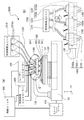
図4は第2実施形態に係る3次元形成装置の構成を示す概略構成図である。図4(a)に示す3次元形成装置2000(以下、形成装置2000という)は、第1実施形態に係る形成装置1000に対して、材料供給手段の構成と、ヘッドベースおよびヘッドユニットの構成が異なるものである。従って、第1実施形態に係る形成装置1000と同じ構成要素には同じ符号を付し、説明は省略する。
(Second Embodiment)
FIG. 4 is a schematic configuration diagram showing the configuration of the three-dimensional forming apparatus according to the second embodiment. The three-dimensional forming apparatus 2000 (hereinafter referred to as the forming apparatus 2000) shown in FIG. Is different. Accordingly, the same components as those of the forming
図4に示すように、形成装置2000は、基台110と、基台110に備える駆動手段としての駆動装置111によって、図示するX,Y,Z方向の移動、あるいはZ軸を中心とする回転方向に駆動可能に備えられたステージ120と、一方の端部が基台110に固定され、他方の端部に、エネルギー照射部1300と材料吐出部1230とを備えるヘッドユニット1400を複数保持するヘッドベース1100が保持固定されるヘッドベース支持部130と、を備えている。
As shown in FIG. 4, the forming
そしてステージ120上に、3次元形状造形物500に形成される過程での部分造形物501,502,503が層状に形成される。3次元形状造形物500の形成には後述するが、レーザーによる熱エネルギーの照射がされるため、ステージ120の熱からの保護のため、耐熱性を有する試料プレート121を用いて、試料プレート121の上に3次元形状造形物500を形成してもよい。試料プレート121としては、例えばセラミック板を用いることで、高い耐熱性を得ることができ、更に焼結あるいは熔融される供給材料との反応性も低く、3次元形状造形物500の変質を防止することができる。なお、図4(a)では説明の便宜上、部分造形物501,502,503の3層を例示したが、所望の3次元形状造形物500の形状まで積層される。
Then, partial shaped
図4(b)は、図4(a)に示すヘッドベース1100を示すC部拡大概念図である。図4(b)に示すように、ヘッドベース1100は、複数のヘッドユニット1400が保持されている。詳細は後述するが、1つのヘッドユニット1400は、材料供給手段としての材料供給装置1200に備える材料吐出部1230と、エネルギー照射手段としてのエネルギー照射部1300と、が保持治具1400aに保持されることで構成される。材料吐出部1230は、吐出ノズル1230aと、材料供給コントローラー1500によって吐出ノズル1230aからの材料を吐出させる吐出駆動部1230bと、を備えている。
FIG. 4B is an enlarged conceptual view of a C portion showing the
エネルギー照射部1300は、本実施形態ではエネルギーとしてレーザーを照射するエネルギー照射部1300により説明する(以下、エネルギー照射部1300をレーザー照射部1300という)。ターゲットとなる供給材料に集中してエネルギーを照射することができ、品質の良い3次元形状造形物を形成することができる。また、例えば被焼結材料の種類に合わせて、照射エネルギー量(パワー、走査速度)を制御することが容易に行うことができ、所望の品質の3次元形状造形物を得ることができる。
In this embodiment, the
材料吐出部1230は、ヘッドベース1100に保持されるヘッドユニット1400それぞれに対応させた供給材料を収容した材料供給ユニット1210と供給チューブ1220により接続されている。そして、所定の材料が材料供給ユニット1210から材料吐出部1230に供給される。材料供給ユニット1210には、本実施形態に係る形成装置2000によって造形される3次元形状造形物500の原料を含む被焼結材料が供給材料として材料収容部1210aに収容され、個々の材料収容部1210aは、供給チューブ1220によって、個々の材料吐出部1230に接続されることが好ましい。このように、個々の材料収容部1210aを備えることにより、ヘッドベース1100から、複数の異なる種類の被焼結材料を供給することができる。
The
供給材料の被焼結材料としては、3次元形状造形物500の原料となる金属、例えばマグネシウム(Mg)、鉄(Fe)、コバルト(Co)やクロム(Cr)、アルミニウム(Al)、チタン(Ti)、ニッケル(Ni)の単体粉末、もしくはこれらを1つ以上含む合金などの混合粉末を、溶剤と、バインダーとしての増粘剤と、に混練して得られるスラリー状(あるいはペースト状)の混合材料である。
As a material to be sintered as a supply material, a metal that is a raw material of the three-dimensional
図4(a)に示すように、形成装置2000は、例えば図示しないパーソナルコンピューター等のデータ出力装置から出力される3次元形状造形物500の造形用データに基づいて、上述したステージ120、材料供給装置1200に備える材料吐出部1230、およびレーザー照射部1300を制御する制御手段としての制御ユニット400を備えている。制御ユニット400には、図示されないが、少なくともステージ120の駆動制御部と、材料吐出部1230の作動制御部と、レーザー照射部1300の作動制御部と、を備えている。そして、制御ユニット400には、ステージ120、材料吐出部1230、およびレーザー照射部1300と、が連携して駆動、動作させる制御部を備えている。
As shown in FIG. 4A, the forming
基台110に移動可能に備えられているステージ120は、制御ユニット400からの制御信号に基づき、ステージコントローラー1500においてステージ120の移動開始と停止、移動方向、移動量、移動速度などを制御する信号が生成され、基台110に備える駆動装置111に送られ、図示するX,Y,Z方向にステージ120が移動する。ヘッドユニット1400に備える材料吐出部1230では、制御ユニット400からの制御信号に基づき、材料供給コントローラー440において材料吐出部1230に備える吐出駆動部1230bにおける吐出ノズル1230aからの材料吐出量などを制御する信号が生成され、生成された信号により吐出ノズル1230aから所定量の材料が吐出される。
A
図5および図6は、ヘッドベース1100に複数保持されるヘッドユニット1400、およびヘッドユニット1400に保持されるレーザー照射部1300と材料吐出部1230の保持形態の一例を示し、図5は図4(b)に示す矢印D方向からのヘッドベース1100の外観図、図6は図5に示すE−E´部の概略断面図である
5 and 6 show an example of a
図5に示すように、ヘッドベース1100に複数のヘッドユニット1400が、図示しない固定手段によって保持されている。本実施形態に係る形成装置2000のヘッドベース1100では、図下方より第1列目のヘッドユニット1401,1402、第2列目のヘッドユニット1403,1404、第3列目のヘッドユニット1405,1406、そして第4列目のヘッドユニット1407,1408の、8ユニットのヘッドユニット1400を備えている。そして、図示しないが、それぞれのヘッドユニット1401〜1408に備える材料吐出部1230は、吐出駆動部1230bを介して材料供給ユニット1210に供給チューブ1220で繋がれ、レーザー照射部1300はレーザーコントローラー430に繋がれ、保持治具1400aに保持される構成となっている。
As shown in FIG. 5, a plurality of
図6に示すように、材料吐出部1230は吐出ノズル1230aから、ステージ120上に載置された試料プレート121上に向けて被焼結材料M(以下、材料Mという)が吐出される。ヘッドユニット1401では、材料Mが液滴状で吐出される吐出形態を例示し、ヘッドユニット1402では、材料Mが連続体状で供給される吐出形態を例示している。材料Mの吐出形態は、液滴状であっても連続体状であっても、どちらでもよいが、本実施形態では材料Mは液滴状で吐出される形態により説明する。
As shown in FIG. 6, the
吐出ノズル1230aから液滴状に吐出された材料Mは、略重力方向に飛翔し、試料プレート121上に着弾する。レーザー照射部1300は、出射するレーザーLが、材料Mの着弾位置に向かうよう、重力方向に対して所定の傾きを持って保持治具1400aに保持されており、着弾した材料Mに向けてレーザー照射部1300からレーザーLが照射され、材料Mが焼成、焼結し、焼結部50が形成される。この焼結部50の集合体が、試料プレート121上に形成される3次元形状造形物500の部分造形物、例えば部分造形物501(図4参照)として形成される。
The material M discharged in the form of droplets from the
図7、図8および図9は、ヘッドユニット1400の配置と、焼結部50の形成形態と、の関係を概念的に説明する平面図(図4に示すD方向矢視)である。先ず、図7(a)に示すように試料プレート121上の造形起点q1において、ヘッドユニット1401,1402の吐出ノズル1230aから材料Mが吐出され、試料プレート121に着弾した材料Mにレーザー照射部1300からレーザーLが照射され、焼結部50a,50bが形成される。なお、説明の便宜上、平面図であるが焼結部50にはハッチングを施し、試料プレート121の上面に形成される1層目の部分造形物501を例示して説明する。
7, 8, and 9 are plan views conceptually illustrating the relationship between the arrangement of the
先ず、図7(b)に示すように試料プレート121上の部分造形物501の造形起点q1において、図示下方の第1列目のヘッドユニット1401,1402に備える材料吐出部1230から、材料Mが吐出される。吐出された材料Mに対して、ヘッドユニット1401,1402に備えるレーザー照射部1300からレーザーLが照射され焼結部50a,50bが形成される。
First, as shown in FIG. 7B, at the modeling starting point q1 of the partially modeled
ヘッドユニット1401,1402の材料吐出部1230からの材料Mの吐出と、レーザー照射部1300からのレーザーLの照射を継続しながら、試料プレート121をヘッドベース1100に対して相対的にY(+)方向の、図7(b)に示す造形起点q1が2列目のヘッドユニット1403,1404に対応する位置まで移動させる。これによって、焼結部50a,50bは、造形起点q1から試料プレート121の相対移動後の位置q2まで焼結幅tを保持して延設される。さらに、造形起点q1に対応した2列目のヘッドユニット1403,1404から材料Mが吐出され、そこにレーザーLが照射されることで焼結部50c,50dが形成され始める。
While continuing the discharge of the material M from the
図7(b)に示す焼結部50c,50dが形成され始め、ヘッドユニット1403,1404の材料吐出部1230からの材料Mの吐出と、レーザー照射部1300からのレーザーLの照射を継続しながら、試料プレート121をヘッドベース1100に対して相対的にY(+)方向の、図7(c)に示す造形起点q1が3列目のヘッドユニット1405,1406に対応する位置まで移動させる。これによって、焼結部50c,50dは、造形起点q1から試料プレート121の移動後の位置q2まで焼結幅tを保持して延設される。同時に、焼結部50a,50bは、造形起点q1から試料プレート121の相対移動後の位置q3まで焼結幅tを保持して延設される。造形起点q1に対応した3列目のヘッドユニット1405,1406から材料Mが吐出され、そこにレーザーLが照射されることで焼結部50e,50fが形成され始める。
While the sintered
図7(c)に示す焼結部50e,50fが形成され始め、ヘッドユニット1405,1406の材料吐出部1230からの材料Mの吐出と、レーザー照射部1300からのレーザーLの照射を継続しながら、試料プレート121をヘッドベース1100に対して相対的にY(+)方向の、図8(d)に示す造形起点q1が4列目のヘッドユニット1407,1408に対応する位置まで移動させる。これによって、焼結部50e,50fは、造形起点q1から試料プレート121の移動後の位置q2まで焼結幅tを保持して延設される。同時に、焼結部50a,50bは造形起点q1から試料プレート121の相対移動後の位置q4まで、焼結部50c,50dは造形起点q1から試料プレート121の相対移動後の位置q3まで、焼結幅tを保持して延設される。造形起点q1に対応した4列目のヘッドユニット1407,1408から材料Mが吐出され、そこにレーザーLが照射されることで焼結部50g,50hが形成され始める。
While the
位置q5を焼結終了位置とした場合(以下、位置q5を造形終点q5という)、図8(e)に示すように試料プレート121を相対的にヘッドユニット1401,1402が造形終点q5に到達するまで移動させ、焼結部50g,50hは延設される。そして、造形終点q5に到達したヘッドユニット1401,1402では、ヘッドユニット1401,1402に備える材料吐出部1230からの材料Mの吐出と、レーザー照射部1300からのレーザーLの照射と、が停止される。さらに、相対的に試料プレート121をY(+)方向に移動させながら、ヘッドユニット1403,1404,1405,1406,1407,1408が造形終点q5に到達するまで、レーザーLが照射され、図9に示すように、焼結部50a,50b,50c,50d,50e,50f,50g,50hは焼結幅tを保持して造形起点q1から造形終点q5まで形成される。このようにして、造形起点q1から造形終点q5まで試料プレート121を移動させながら、ヘッドユニット1401,1402,1403,1405,1406,1407,1408から順次、材料Mの吐出供給とレーザーLを照射させることで、幅T、長さJの、本実施形態の例示では略矩形の焼結部50を形成することができる。そして、焼結部50の集合体として第1層目の部分造形物501を成形、構成することができる。
When the position q5 is the sintering end position (hereinafter, the position q5 is referred to as a modeling end point q5), the
上述したように、第2実施形態に係る形成装置2000は、試料プレート121を備えるステージ120の移動に同期させ、ヘッドユニット1401,1402,1403,1404,1405,1406,1407,1408に備える材料吐出部1230からの材料Mの吐出供給と、レーザー照射部1300からのレーザーLの照射と、を選択的に行うことで、試料プレート121上に所望の形状の部分造形物501を形成することができる。また、上述したように、ステージ120の移動は、本例ではY軸方向に沿った一方向へ移動させるだけで、図9(f)に示す幅T×長さJの領域内で所望の形状の焼結部50、そして焼結部50の集合体としての部分造形物501を得ることができる。
As described above, the forming
また、材料吐出部1230から吐出される材料Mを、ヘッドユニット1401,1402,1403,1404,1405,1406,1407,1408のいずれか1ユニット、あるいは2ユニット以上からその他ヘッドユニットと異なる材料を吐出供給することもできる。従って、本実施形態に係る形成装置2000を用いることによって、異種材料から形成される複合材部分造形物を有する3次元形状造形物を得ることができる。
Also, the material M discharged from the
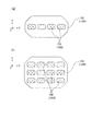
上述の第1実施形態に係る形成装置1000に備えるヘッドベース150に配置されるヘッドユニット160、あるいは第2実施形態に係る形成装置2000に備えるヘッドベース1100に配置されるヘッドユニット1400の数、および配列は、上述した図2あるいは図5に示す数、配列に限定されない。図10に、ヘッドベース150,1100に配置されるヘッドユニット160,1400の、その他の配置の例を模式図的に示す。
The number of
図10(a)は、ヘッドベース150,1100にヘッドユニット160,1400をX軸方向に複数、並列させた形態を示す。図10(b)は、ヘッドベース150,1100にヘッドユニット160,1400を格子状に配列させた形態を示す。なお、いずれも配列されるヘッドユニットの数は、図示の例に限定されない。
FIG. 10A shows a form in which a plurality of
(第3実施形態)
第3実施形態として、第1実施形態に係る3次元形成装置1000を用いて3次元形状造形物を形成する3次元形成方法を説明する。図11は第3実施形態に係る3次元形成方法を示すフローチャートであり、図12はグリーンシート300を成形するグリーンシート成形装置の概略構成図、図13、図14は本実施形態に係る3次元形成工程を示す概略平面図と概略断面図、および図15は本実施形態に係る3次元形成工程を示す外観斜視図と概略断面図である。
(Third embodiment)
As a third embodiment, a three-dimensional forming method for forming a three-dimensional shaped object using the three-dimensional forming
(3次元造形用データ取得工程)
図11に示すように、本実施形態に係る3次元形成方法は、3次元形状造形物の3次元造形用データを、図示しない、例えばパーソナルコンピューターなどから制御ユニット400(図1参照)に取得する、3次元造形用データ取得工程(S1)が実行される。3次元造形用データ取得工程(S1)において取得された3次元造形用データは、制御ユニット400から、ステージコントローラー410と、材料供給装置コントローラー420と、レーザーコントローラー430と、に制御データが送られ、材料準備工程に移行される。
(3D modeling data acquisition process)
As shown in FIG. 11, the three-dimensional formation method according to the present embodiment acquires the three-dimensional modeling data of the three-dimensional modeled object to the control unit 400 (see FIG. 1) from an unillustrated personal computer, for example. A three-dimensional modeling data acquisition step (S1) is executed. The three-dimensional modeling data acquired in the three-dimensional modeling data acquisition step (S1) is sent control data from the
(材料準備工程)
材料準備工程(S2)では、グリーンシート300を材料供給装置200に備える供給テーブル220に、所定枚数が載置される。グリーンシート300は、図12に概略構成を例示する、グリーンシート300のグリーンシート成形装置3000等によって形成される。
(Material preparation process)
In the material preparation step (S2), a predetermined number of sheets are placed on the supply table 220 including the
図12に示すように、グリーンシート成形装置3000は、材料Mを供給する原料供給部3100と、原料供給部3100から排出された材料Mを受け、搬送する搬送ベルト3200と、を備えている。材料Mは、30μm以下に形成された金属粉末と、バインダーと、を混練しペースト状となった混合物を用いる。金属粉末としては、例えばコバルト系合金、マルエージング鋼、ステンレス鋼、チタン系合金、ニッケル系合金、マグネシウム合金、あるいは銅系合金などの合金、あるいは鉄、チタン、ニッケル、銅などの金属を用いることができる。バインダーとしては、熱可塑性樹脂、あるいは水溶性熱可塑性樹脂を用いることができる。熱可塑性樹脂としては、例えばポリ乳酸(PLA)、ポリプロピレン(PP)、ポリフェニレンスルファイド(PPS)、ポリアミド(PA)、ABS、ポリエーテルエーテルケトン(PEEK)等が用いられ、水溶性熱可塑性樹脂としては、例えばポリビニルアルコール(PVA)、ポリビニルブチラール(PVB)等が用いられる。
As illustrated in FIG. 12, the green
上述した金属粉末と、バインダー、そして粘度調整用としての溶剤が加えられ、混練された材料Mが原料供給部3100に投入され、図示矢印α方向に駆動される搬送ベルト3200上に所定量が順次排出される。搬送ベルト3200のα方向移動によって材料Mは、均一化ロール3300によって、均一な厚みに形成され、次の加圧ローラー3400を通過し、グリーンシート300となる所定の厚みに形成される。そして、切断手段3500によって所定の長さで切断され、グリーンシート300が得られる。
The metal powder, the binder, and the viscosity adjusting solvent described above are added, and the kneaded material M is charged into the raw
(材料供給工程)
材料準備工程(S2)によって、材料供給装置200の供給テーブル220上に所定数のグリーンシート300が載置されると、材料供給工程(S3)が開始される。材料供給工程(S3)では、制御ユニット400からの制御信号に基づいて、材料供給装置コントローラー420は、移送装置230の駆動信号を生成し、移送装置230を駆動させる。
(Material supply process)
When a predetermined number of
先ず、シート保持部230aを所定の位置まで移動させ、供給テーブル220上に積載されたグリーンシート300の最上シートをシート吸着部230cによって吸着、保持する。グリーンシート300を保持した状態で、シート保持部230aは焼結装置100の試料プレート121上に移動し、グリーンシート300をシート吸着部230cから離脱、離間させ、グリーンシート300が試料プレート121上に載置される。グリーンシート300が載置、離間された後、シート保持部230aは材料供給装置200の待機位置まで戻される。以下、1層目として載置されたグリーンシート300を、第1層目のグリーンシート301として説明する。
First, the
(焼結工程)
材料供給工程(S3)によって試料プレート121上に載置された第1層目のグリーンシート301に対して、ヘッドベース150に複数保持されたヘッドユニット160に備えるレーザー照射部140からレーザーLが照射される焼結工程(S4)に移行される。焼結工程(S4)における焼結とは、グリーンシート300を構成する金属粉末およびバインダーが混練された状態から、バインダーを蒸散させ、金属粉末同士を結合させ、金属粉末状態から、金属造形物に成形する加工手段である。
(Sintering process)
Laser L is irradiated from a
図13(a)、図13(b)および図14(c)に、焼結工程(S3)における第1層目のグリーンシート301の焼結部311の形成方法を示す。本例では、3次元形状造形物500を構成する円環状の1層目の部分造形物501を形成する方法を例示する。図13および図14は、図示上方に平面図、下方に平面図に示すF−F´部の断面図を示す。図13(a)に示すように、ヘッドベース150とステージ120上に備える試料プレート121に載置された1層目のグリーンシート301と、を相対的にY方向に移動させながらヘッドベース150に配置されたヘッドユニット160(本図では図示せず)に備えるレーザー照射部140からレーザーLを、グリーンシート301に向けて照射する。
FIGS. 13A, 13B, and 14C show a method of forming the
ヘッドベース150を所定量の相対移動が終了することで、図3(d)において説明した、各レーザー照射部140から照射されて形成される焼結部310a,310b,310c,310d,310e,310fに相当する焼結部の集合体としての焼結部310が形成され、部分造形物501を構成する最初の焼結部311が形成される。そして、図13(b)に示すように、ヘッドベース150は、図13(a)に示す焼結部310に連続するように図3(d)において説明した、各レーザー照射部140から照射されて形成される焼結部310a,310b,310c,310d,310e,310fに相当する焼結部の集合体を形成し、焼結部312が形成され、焼結部311と連なる焼結部310が形成される。
When the relative movement of the
そして、図13(b)に示す、ヘッドベース150を、図13(a)で形成された焼結部310に連続するように図3(d)において説明した、各レーザー照射部140から照射されて形成される焼結部310a,310b,310c,310d,310e,310fに相当する焼結部の集合体を形成することを順次、所定の繰り返し数実施し、図14(c)に示すように、焼結部310が部分造形物501の形状まで形成されるi番目の焼結部31iが形成され、第1層目のグリーンシート301内に部分造形物501と、部分造形物501を除く部分、すなわち未焼結部301aと、が形成される。
Then, the
こうして、焼結工程(S4)において、焼結された部分造形物501と、未焼結部301aと、が形成され、第一の単層としての第1層301bが形成される。以上の、材料供給工程(S3)から焼結工程(S4)に至る一連の工程が単層形成工程(S100)である。そして、焼結工程(S4)の終了、すなわち単層形成工程(S100)が終了し、次の積層数比較工程に移行される。
Thus, in the sintering step (S4), the sintered partially shaped
(積層数比較工程)
単層形成工程(S100)によって、第1層となる部分造形物501と、未焼結部301aと、を含む第1層301bが形成されると、3次元造形用データ取得工程(S1)によって得られた造形データと比較する積層数比較工程(S5)に移行される。積層数比較工程(S5)では、3次元形状造形物500を構成するために必要な部分造形物が形成されたグリーンシート300の積層数Nと、積層数比較工程(S5)の直前の単層形成工程(S100)までで積層されたグリーンシート300の積層数nと、を比較する。積層数比較工程(S5)において、n<Nと判定された場合、再度、単層形成工程(S100)を実行させる積層工程に移行される。
(Stacking number comparison process)
When the
(積層工程)
積層工程(S6)は、積層数比較工程(S5)において、n<Nと判定され、再度、単層形成工程(S100)を実行させるための指令工程であり、単層形成工程(S100)の開始工程である材料供給工程(S3)を実行させる。
(Lamination process)
The stacking process (S6) is a command process for determining that n <N in the stacking number comparison process (S5), and executing the single layer forming process (S100) again. The material supply process (S3) which is a start process is performed.
図14(d)に示すように、積層工程(S6)によって第1層301bの上部に、グリーンシート300が供給、載置され、第2層目のグリーンシート302となる。そして、第2層目のグリーンシート302に対して、図13(a),(b)および図14(d)に示す焼結工程(S5)が行われ、2層目の部分造形物502と、図示しない未焼結部と、が形成された、第二の単層としての第2層302bが得られる。その後、積層数比較工程(S6)に移行され、n<Nと判定されると、再び積層工程(S6)が開始され、積層数比較工程(S5)において、n=Nと判定されるまで、積層工程(S6)及び単層形成工程(S100)が繰り返される。
As shown in FIG. 14D, the
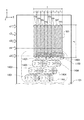
図15(e)に示すように、所定の積層数Nまで積層されると、3次元形状造形物500が試料プレート121上に形成される。また、第1層301bから第N層30Nbまで積層されて形成された未焼結部300aも、試料プレート121上に形成される。そして、積層数比較工程(S5)で、n=Nと判定され、未焼結部除去工程に移行される。
As shown in FIG. 15 (e), when a predetermined number N of layers are stacked, a three-dimensional
(未焼結部除去工程)
未焼結部除去工程(S7)は、3次元形状造形物500を除く部分、すなわち未焼結部300aを除去する工程である。未焼結部300aの除去方法は、機械的に除去する方法、溶剤によって未焼結部300aに含むバインダーを溶解し、残った金属粉末を除去する方法、などが適用されるが、本形態では機械的な除去を例に説明する。
(Unsintered part removal process)
The unsintered portion removing step (S7) is a step of removing the portion excluding the three-dimensional
図15(f)に示すように、未焼結部除去工程(S7)では、楔状の先端を有する除去工具600を未焼結部300aに打ち込むことで未焼結部300aが粉砕され、試料プレート121上から未焼結部300aが除去される。そして、試料プレート121上には3次元形状造形物500が残り、これを取り出す。なお、本形態では試料プレート121上で未焼結部除去工程(S7)が行われることとして説明したが、別に設けられた作業台上で行ってもよい。
As shown in FIG. 15 (f), in the unsintered portion removing step (S7), the
以上、説明した第3実施形態に係る3次元形状造形物500の3次元形成方法では、単層形成工程(S100)における焼結工程(S5)では、焼結装置100に備えるヘッドベース150に、レーザー照射部140を備えるヘッドユニット160を複数備えていることで、ヘッドベース150とステージ120と、の相対移動を一方向、本例ではY軸方向とするだけで、広い領域での焼結部310を形成することができ、高い生産性を有する3次元形成方法を得ることができる。
As described above, in the three-dimensional forming method of the three-dimensional
(第4実施形態)
第4実施形態として、第2実施形態に係る3次元形成装置2000を用いて3次元形状造形物を形成する3次元形成方法を説明する。図16は第4実施形態に係る3次元形成方法を示すフローチャートであり、図17、図18は本実施形態に係る3次元形成工程を示し、図示上方に概略平面図、下方に概略平面図に示すG−G´部の概略断面図を示す。
(Fourth embodiment)
As the fourth embodiment, a three-dimensional forming method for forming a three-dimensional shaped object using the three-dimensional forming
(3次元造形用データ取得工程)
図16に示すように、本実施形態に係る3次元形成方法は、3次元形状造形物500の3次元造形用データを、図示しない、例えばパーソナルコンピューターなどから制御ユニット400(図4参照)に取得する、3次元造形用データ取得工程(S10)が実行される。3次元造形用データ取得工程(S10)において取得された3次元造形用データは、制御ユニット400から、ステージコントローラー410と、材料供給コントローラー1500と、レーザーコントローラー430と、に制御データが送られ、単層形成工程に移行される。
(3D modeling data acquisition process)
As shown in FIG. 16, the three-dimensional formation method according to the present embodiment acquires the data for three-dimensional modeling of the three-dimensional modeled
(単層形成工程)
単層形成工程(S110)は、材料供給工程(S20)と、焼結工程(S30)と、が第1層目の部分造形物501の形成領域にわたって行われる。材料供給工程(S20)では、ヘッドベース1100に複数備えられたヘッドユニット1400に保持された材料吐出部1230から、試料プレート121上に向けて材料Mを液滴状に吐出し、試料プレート121上に材料Mを所定の形成領域に着弾させる。
(Single layer formation process)
In the single layer formation step (S110), the material supply step (S20) and the sintering step (S30) are performed over the formation region of the partially shaped
材料供給工程(S20)によって材料Mが試料プレート121上に着弾、形成されると、焼結工程(S30)に移行される、焼結工程(S30)は、材料供給工程(S20)によって液滴状に供給された材料Mに向かって、ヘッドユニット1400に保持されたレーザー照射部1300からレーザーLが照射され、材料Mを焼成、焼結し焼結部50を形成する。
When the material M is landed and formed on the
そして、図9(f)において説明したように、ヘッドユニット1401,1402,1403,1404,1405,1406,1407,1408の各々が、所定の領域で材料供給工程(S20)と、焼結工程(S30)と、を繰り返しながらヘッドベース1100を試料プレート121が載置されたステージ120に対して相対的にY軸方向に移動させることによって、焼結部50a,50b,50c,50d,50e,50f,50g,50hに相当する焼結部の集合体を形成し、部分造形物501の初めの焼結部50が焼結部511として形成される。
9 (f), each of the
更に、図17(b)に示すようにヘッドベース1100は、図17(a)に示す焼結部511に連続するように焼結部50a,50b,50c,50d,50e,50f,50g,50hに相当する焼結部が形成される位置にステージ120に対して相対的にX軸方向に移動させる。そして、ヘッドユニット1401,1402,1403,1404,1405,1406,1407,1408の各々が、所定の領域で材料供給工程(S20)と、焼結工程(S30)と、を繰り返しながらヘッドベース1100を試料プレート121が載置されたステージ120に対して相対的にY軸方向に移動させることによって、焼結部50a,50b,50c,50d,50e,50f,50g,50hに相当する焼結部の集合体を形成し、焼結部511に連続する焼結部512として形成される。すなわち焼結部511,512によって焼結部50が構成される。
Further, as shown in FIG. 17 (b), the
上述の図17(b)に示すように、先に形成された焼結部511に連続して焼結部512を形成するように、焼結部512に連続させ、順次焼結部を形成し、図18(c)に示すように、焼結部50が部分造形物501の形状まで形成されるi番目の焼結部51iが形成され、3次元形状造形物500の第1層目の部分造形物501が試料プレート121上に形成される。
As shown in FIG. 17 (b) described above, the
上述した通り、本実施形態ではヘッドベース1100を試料プレート121に対してY軸方向と、X軸方向と、に相対移動させながら材料供給工程(S20)と、焼結工程(S30)と、を繰り返し、第1層目の部分造形物501が形成されることで単層形成工程(S110)が終了し、次の積層数比較工程に移行される。
As described above, in the present embodiment, the material supply step (S20) and the sintering step (S30) are performed while the
(積層数比較工程)
単層形成工程(S110)によって、第一の単層としての第1層目となる部分造形物501が形成されると、3次元造形用データ取得工程(S10)によって得られた造形データと比較する積層数比較工程(S40)に移行される。積層数比較工程(S40)では、3次元形状造形物500を構成する部分造形物の積層数Nと、積層数比較工程(S40)の直前の単層形成工程(S110)までで積層された部分造形物の積層数nと、を比較する。積層数比較工程(S40)において、n<Nと判定された場合、再度、単層形成工程(S110)を実行させる積層工程に移行される。
(Stacking number comparison process)
When the partially shaped
図18(c)に示す第一の単層としての第1層目の部分造形物501が形成された後の積層数比較工程(S40)では、積層数n=1であり、3次元形状造形物500が部分造形物の積層数N>1であるとすると、n<Nと判定され、積層工程に移行される。
In the stacking number comparison step (S40) after the first layer partially shaped
(積層工程)
積層工程(S50)は、積層数比較工程(S40)においてn<Nと判定され、再度単層形成工程(S110)を実行させるための指令工程である。単層形成工程(S110)に移行されると、図18(d)に示すように、積層工程(S50)によって第1層目の部分造形物501の上部に、第二の単層としての第2層目となる部分造形物502に対応する3次元造形データに基づき、材料供給工程(S20)と、焼結工程(S30)と、開始される位置に、ヘッドベース1100、およびステージ120が駆動され、部分造形物502の形成が開始される。
(Lamination process)
The stacking step (S50) is a command step for determining n <N in the stacking number comparison step (S40) and causing the single layer forming step (S110) to be executed again. When the process proceeds to the single layer forming step (S110), as shown in FIG. 18 (d), the first layer as the second single layer is formed on the top of the first layer partially shaped
2層目の部分造形物502の形成が終了すると、再度、積層数比較工程(S40)に移行し、n=Nとなるまで、積層工程(S50)へ移行され、単層形成工程(S110)が繰り返され、3次元形状造形物500が形成される。
When the formation of the second layer partially shaped
以上、説明した第4実施形態に係る3次元形状造形物500の3次元形成方法では、単層形成工程(S110)における材料供給工程(S20)および焼結工程(S30)では、形成装置2000に備えるヘッドベース1100に、材料吐出部1230とレーザー照射部1300を備えるヘッドユニット1400を複数備えていることで、ヘッドベース1100とステージ120と、の相対移動を一方向、本例ではY軸方向とするだけで、広い領域での焼結部50を形成することができ、高い生産性を有する3次元形成方法を得ることができる。
As described above, in the three-dimensional formation method of the three-dimensionally shaped
また、図4に示す形成装置2000に備える材料供給ユニット1210に、複数の異なる種類の被焼結材料を材料収容部1210aに収容させることで、異なる種類の材料からなる3次元形状造形物500を、容易に得ることができる。
In addition, the
(第5実施形態)
第5実施形態に係る3次元形成方法について説明する。上述した第4実施形態に係る3次元形成方法において、3次元形状造形物がオーバーハング部を有する場合、オーバーハング部では、上述した単層形成工程(S110)における材料供給工程(S20)では、材料吐出部1230から吐出された材料Mが着弾すべき下層の部分造形物が存在しないことで、材料Mが形成されなくなる(図18(d)参照)。仮に、図18(d)に示す、下層の部分造形としての第1層目の部分造形物501が、第2層目の部分造形物502の造形領域において配置されていない領域が存在すると、その部分では部分造形物502重力方向へ垂れ下がるように変形する虞がある。すなわち焼結前の材料Mは、原料となる金属、例えばステンレス、チタン合金の単体粉末、もしくは合金化が困難なステンレスと銅(Cu)、あるいはステンレスとチタン合金、あるいはチタン合金とコバルト(Co)やクロム(Cr)、などの混合粉末を、溶剤と、増粘剤と、に混練して得られるスラリー状(あるいはペースト状)の柔らかな状態のものであることによる。
(Fifth embodiment)
A three-dimensional forming method according to the fifth embodiment will be described. In the three-dimensional formation method according to the fourth embodiment described above, when the three-dimensional shaped object has an overhang portion, in the material supply step (S20) in the single layer formation step (S110) described above, in the overhang portion, The material M is not formed because there is no lower-layer partially shaped object to which the material M discharged from the
そこで、第5実施形態に係る3次元形成方法によりオーバーハング部を変形させないで3次元形状造形物を形成する方法を説明する。なお、第4実施形態に係る3次元形成方法と同じ工程には同じ符号を付し、説明は省略する。また、説明を簡略にするために図19(a)の平面外観図、および図19(b)の図19(a)に示すK−K´部の断面図に示すような、単純な形状を有する3次元形状造形物700を例示して、第5実施形態に係る3次元形成方法を説明するが、この形状に限定されず、いわゆるオーバーハング部を備える造形物であれば適用できる。
Therefore, a method of forming a three-dimensional shaped object without deforming the overhang portion by the three-dimensional forming method according to the fifth embodiment will be described. In addition, the same code | symbol is attached | subjected to the same process as the three-dimensional formation method which concerns on 4th Embodiment, and description is abbreviate | omitted. In order to simplify the description, a simple shape as shown in a plan view of FIG. 19A and a cross-sectional view of the KK ′ section shown in FIG. 19A of FIG. The three-dimensional
図19に示すように、3次元形状造形物700は、凹部700aを有する円柱形の基部700bの凹部開口側端部に基部700bの外側に延在するオーバーハング部としての鍔部700cを備えている。この3次元形状造形物700を、第5実施形態に係る3次元形成方法に基づいて形成するために、形成過程において除去されるサポート部710が、鍔部700cの図示下部方向に基部700bの底部に至るまでの造形用データが、3次元形状造形物700の3次元造形用データに加えて作成される。
As shown in FIG. 19, the three-dimensional
図20は、図19に示す3次元形状造形物700の形成方法を示すフローチャートである。また図21は図20に示すフローチャートによる3次元形状造形物700の形成方法を示し、図示左側に部分断面図、右側に平面外観図を配置した。また、本実施形態の3次元形状造形物700では、4層が積層されて形成される例を用いて説明するが、これに限定されるものではない。
FIG. 20 is a flowchart showing a method for forming the three-dimensional
先ず、図21(a)に示すように、図示しない試料プレート121上に第1層目となる部分造形物701が、第4実施形態に係る3次元形成方法によって形成される。部分造形物701を形成する工程内に、第1層目の部分サポート部711も形成される。部分サポート部711は、図17及び図18によって説明した単層形成工程(S110)における焼結工程(S30)は実行されず、材料Mの状態のまま、すなわち未焼結部、あるいは未熔融部のままで単層形成工程(S110)が実行される。
First, as shown to Fig.21 (a), the partial shaped
引き続き、単層形成工程(S110)が繰り返され、図21(b)に示すように、第2層目および第3層目となる部分造形物702,703が形成される。そして、部分造形物702,703を形成する工程内に、第2層目および第3層目の部分サポート部712,713も形成される。部分サポート部712,713は、部分サポート部711同様に、単層形成工程(S110)における焼結工程(S30)は実行されず、材料Mの状態のまま、すなわち未焼結部、あるいは未熔融部のままで単層形成工程(S110)が実行され、部分サポート部711,712,713によって、サポート部710が形成される。
Subsequently, the single layer forming step (S110) is repeated, and as shown in FIG. 21B, partial shaped
次に図21(c)に示すように、鍔部700cに形成される第4層目の部分造形物704が形成される。部分造形物704は、部分サポート部711,712,713によって形成されたサポート部710の端面710aに支持されるように形成される。このように部分造形物704を形成することにより、材料M(図18(d)参照)が着弾する面として端面710aが形成されていることで、正確に鍔部700cとなる第4層目の部分造形物704を形成することができる。
Next, as shown in FIG. 21 (c), a fourth-layer partially shaped
そして、図21(d)に示すように、3次元形状造形物700に造形されたところで、サポート部除去工程(S60)によって、サポート部710は3次元形状造形物700から除去される。サポート部710は焼成されていない材料で形成されていることから、サポート部除去工程(S60)におけるサポート部710の除去手段としては、例えば図21(d)に示すように鋭利な刃物800による物理的な切除が可能である。あるいは、溶剤に浸漬し、材料に含まれる増粘剤を溶解し3次元形状造形物700から除去してもよい。
Then, as shown in FIG. 21 (d), when the three-dimensional
上述したように、オーバーハング部としての鍔部700cを有する3次元形状造形物700を形成する場合、鍔部700cを支持するサポート部710を3次元形状造形物700の形成と合わせて形成することにより、鍔部700cの重力方向への変形を防止することができる。なお、図21に示すサポート部710は、図示するような鍔部700cを全面でサポート(支持)する形態に限定されず、造形物の形状、材料組成などによって適宜、形状、大きさ等が設定される。
As described above, when forming the three-dimensional
なお、本発明の実施の際の具体的な構成は、本発明の目的を達成できる範囲で他の装置、あるいは方法に適宜変更できる。 It should be noted that the specific configuration in carrying out the present invention can be changed as appropriate to other apparatuses or methods within the scope of achieving the object of the present invention.
100…焼結装置、110…基台、120…ステージ、130…ヘッドベース支持部、140…エネルギー照射部、150…ヘッドベース、170…プレスローラー、200…材料供給装置、210…供給基台、220…供給テーブル、230…移送装置、400…制御ユニット、410…ステージコントローラー、420…材料供給装置コントローラー、430…レーザーコントローラー、1000…3次元形成装置。
DESCRIPTION OF
Claims (8)
金属粉末と、バインダーと、が混練された被焼結材料を前記ステージに供給する材料供給手段と、
前記材料供給手段により供給された前記被焼結材料に、前記被焼結材料を焼結可能とするエネルギーを供給するエネルギー照射部を備えるヘッドユニットと、
前記ヘッドユニットを複数保持するヘッドベースと、を備え、
前記ステージに対して、前記ヘッドベースが、相対的に3次元移動が可能となる駆動手段を備える、
ことを特徴とする3次元形成装置。 Stage,
A material supply means for supplying a material to be sintered in which metal powder and a binder are kneaded to the stage;
A head unit including an energy irradiation unit that supplies energy to enable sintering of the material to be sintered to the material to be sintered supplied by the material supply unit;
A head base for holding a plurality of the head units,
The head base includes a driving unit that is relatively three-dimensionally movable with respect to the stage.
A three-dimensional forming apparatus.
金属粉末と、バインダーと、が混練された被焼結材料を前記ステージに供給する材料吐出部を備える材料供給手段と、
前記材料供給手段により供給された前記被焼結材料に、前記被焼結材料を焼結可能とするエネルギーを供給するエネルギー照射部と、を備え、
前記材料吐出部と、前記エネルギー照射部と、が保持されたヘッドユニットを複数保持するヘッドベースを備え、
前記ステージに対して、前記ヘッドベースが、相対的に3次元移動が可能となる駆動手段を備える、
ことを特徴とする3次元形成装置。 Stage,
A material supply means comprising a material discharge section for supplying a material to be sintered in which metal powder and a binder are kneaded to the stage;
An energy irradiation unit that supplies energy to enable sintering of the material to be sintered to the material to be sintered supplied by the material supply unit;
A head base for holding a plurality of head units in which the material discharge unit and the energy irradiation unit are held;
The head base includes a driving unit that is relatively three-dimensionally movable with respect to the stage.
A three-dimensional forming apparatus.
ことを特徴とする請求項2に記載の3次元形成装置。 Among the plurality of material supply means, the material supply means including the material discharge part held by at least one of the head units and the other material supply means include the material to be sintered accommodated therein. Different,
The three-dimensional forming apparatus according to claim 2.
前記被焼結材料を焼結可能とするエネルギーを供給するエネルギー照射部を備えるヘッドユニットを複数保持するヘッドベースを、前記ステージに対して相対的に移動させ、前記エネルギーを前記被焼結材料に向けて供給し、前記被焼結材料を焼結させる焼結工程と、により単層を形成する単層形成工程と、
前記単層形成工程によって形成された第一の単層に積層させ、前記単層形成工程によって第二の単層を形成する積層工程と、を含み、
前記積層工程を所定の回数、繰り返す、
ことを特徴とする3次元形成方法。 A material supply step of supplying a material to be sintered in which metal powder and a binder are kneaded to the stage;
A head base that holds a plurality of head units each having an energy irradiation unit that supplies energy that enables sintering of the material to be sintered is moved relative to the stage, and the energy is transferred to the material to be sintered. A single layer forming step of forming a single layer by a sintering step of sintering and sintering the material to be sintered,
Laminating to the first single layer formed by the single layer forming step, and forming a second single layer by the single layer forming step,
Repeating the lamination step a predetermined number of times,
The three-dimensional formation method characterized by the above-mentioned.
前記単層形成工程によって形成された第一の単層に積層させ、前記単層形成工程によって第二の単層を形成する積層工程と、を含み、
前記積層工程を所定の回数、繰り返す、
ことを特徴とする3次元形成方法。 A material discharge unit provided in a material supply means for supplying a material to be sintered in which metal powder and a binder are kneaded to the stage, and the material to be sintered supplied to the material to be sintered supplied by the material supply means An energy irradiating unit that supplies energy that enables sintering, and a head base that holds a plurality of head units that are held relative to the stage is moved relative to the stage from the material discharge unit to the stage. A material supplying step for discharging the material to be sintered, and a sintering step for supplying the energy to the material to be sintered discharged in the material supplying step to sinter the material to be sintered. A single layer forming step of forming a single layer;
Laminating to the first single layer formed by the single layer forming step, and forming a second single layer by the single layer forming step,
Repeating the lamination step a predetermined number of times,
The three-dimensional formation method characterized by the above-mentioned.
ことを特徴とする請求項6に記載の3次元形成方法。 Among the plurality of material supply means, the material supply means including the material discharge part held by at least one of the head units and the other material supply means include the material to be sintered accommodated therein. Different,
The three-dimensional formation method according to claim 6.
Priority Applications (6)
| Application Number | Priority Date | Filing Date | Title |
|---|---|---|---|
| JP2015106177A JP2016216801A (en) | 2015-05-26 | 2015-05-26 | Three-dimensional forming apparatus and three-dimensional forming method |
| CN201610322259.7A CN106180706B (en) | 2015-05-26 | 2016-05-16 | Three-dimensional forming apparatus and three-dimensional forming method |
| CN202010373527.4A CN111468725A (en) | 2015-05-26 | 2016-05-16 | Three-dimensional modeling method |
| US15/163,287 US10717231B2 (en) | 2015-05-26 | 2016-05-24 | Three-dimensional forming apparatus and three-dimensional forming method |
| EP16171369.8A EP3098001A1 (en) | 2015-05-26 | 2016-05-25 | Three-dimensional forming apparatus and three-dimensional forming method |
| US16/807,932 US20200198232A1 (en) | 2015-05-26 | 2020-03-03 | Three-dimensional forming apparatus and three-dimensional forming method |
Applications Claiming Priority (1)
| Application Number | Priority Date | Filing Date | Title |
|---|---|---|---|
| JP2015106177A JP2016216801A (en) | 2015-05-26 | 2015-05-26 | Three-dimensional forming apparatus and three-dimensional forming method |
Publications (1)
| Publication Number | Publication Date |
|---|---|
| JP2016216801A true JP2016216801A (en) | 2016-12-22 |
Family
ID=56137089
Family Applications (1)
| Application Number | Title | Priority Date | Filing Date |
|---|---|---|---|
| JP2015106177A Pending JP2016216801A (en) | 2015-05-26 | 2015-05-26 | Three-dimensional forming apparatus and three-dimensional forming method |
Country Status (4)
| Country | Link |
|---|---|
| US (2) | US10717231B2 (en) |
| EP (1) | EP3098001A1 (en) |
| JP (1) | JP2016216801A (en) |
| CN (2) | CN111468725A (en) |
Cited By (2)
| Publication number | Priority date | Publication date | Assignee | Title |
|---|---|---|---|---|
| WO2018235062A1 (en) * | 2017-06-19 | 2018-12-27 | 株式会社エンプラス | Powder for powder laminate shaping |
| KR20200016348A (en) * | 2017-07-06 | 2020-02-14 | 휴렛-팩커드 디벨롭먼트 컴퍼니, 엘.피. | 3D printing |
Families Citing this family (9)
| Publication number | Priority date | Publication date | Assignee | Title |
|---|---|---|---|---|
| WO2019022755A1 (en) * | 2017-07-28 | 2019-01-31 | Hewlett-Packard Development Company, L.P. | Three-dimensional printer with movement device |
| DE102017126697A1 (en) * | 2017-11-14 | 2019-05-16 | Sklt Strahlkraft Lasertechnik Gmbh | Method and device for joining workpieces |
| JP6950583B2 (en) * | 2018-03-02 | 2021-10-13 | トヨタ自動車株式会社 | Mold manufacturing method |
| US11072039B2 (en) * | 2018-06-13 | 2021-07-27 | General Electric Company | Systems and methods for additive manufacturing |
| US10919115B2 (en) * | 2018-06-13 | 2021-02-16 | General Electric Company | Systems and methods for finishing additive manufacturing faces with different orientations |
| US11203062B2 (en) * | 2018-07-11 | 2021-12-21 | G. B. Kirby Meacham | Additive metal manufacturing process |
| JP7119890B2 (en) * | 2018-10-22 | 2022-08-17 | セイコーエプソン株式会社 | Apparatus for manufacturing three-dimensional model and method for manufacturing three-dimensional model |
| RU2713254C1 (en) * | 2019-07-29 | 2020-02-04 | Общество с ограниченной ответственностью "Малое инновационное предприятие "Центр компетенций аддитивных технологий" (ООО "МИП "ЦКАТ") | Method of making articles from metal powders |
| JP2022072580A (en) * | 2020-10-30 | 2022-05-17 | セイコーエプソン株式会社 | Three-dimensional molding apparatus |
Citations (5)
| Publication number | Priority date | Publication date | Assignee | Title |
|---|---|---|---|---|
| JP2005095849A (en) * | 2003-02-26 | 2005-04-14 | Seiko Epson Corp | Method and device for fixing functional material, device manufacturing method, electro-optic device and electronic instrument |
| WO2014107204A2 (en) * | 2012-10-08 | 2014-07-10 | Siemens Aktiengesellschaft | Additive manufacture of turbine component with multiple materials |
| US20140246809A1 (en) * | 2013-03-04 | 2014-09-04 | California Institute Of Technology | Systems and methods implementing additive manufacturing processes that utilize multiple build heads |
| WO2014199134A1 (en) * | 2013-06-10 | 2014-12-18 | Renishaw Plc | Selective laser solidification apparatus and method |
| JP2015096646A (en) * | 2013-10-11 | 2015-05-21 | セイコーエプソン株式会社 | Powder for laser sintering and method and apparatus for production of structure |
Family Cites Families (20)
| Publication number | Priority date | Publication date | Assignee | Title |
|---|---|---|---|---|
| JPS61264168A (en) | 1985-05-16 | 1986-11-22 | Agency Of Ind Science & Technol | Laser spraying method and its apparatus |
| JP3433219B2 (en) | 1998-11-17 | 2003-08-04 | 独立行政法人産業技術総合研究所 | Manufacturing method of metal or ceramic products |
| US6259962B1 (en) | 1999-03-01 | 2001-07-10 | Objet Geometries Ltd. | Apparatus and method for three dimensional model printing |
| JP2001334581A (en) * | 2000-05-24 | 2001-12-04 | Minolta Co Ltd | Three-dimensional molding apparatus |
| US20020149137A1 (en) * | 2001-04-12 | 2002-10-17 | Bor Zeng Jang | Layer manufacturing method and apparatus using full-area curing |
| WO2003034314A1 (en) * | 2001-10-15 | 2003-04-24 | The Regents Of The University Of Michigan | Solid freeform fabrication of structurally engineered multifunctional devices |
| WO2005056221A1 (en) * | 2003-12-11 | 2005-06-23 | Keijirou Yamamoto | Laminate molding method and laminate molding device |
| JP4299157B2 (en) | 2004-02-03 | 2009-07-22 | トヨタ自動車株式会社 | Powder metal overlay nozzle |
| JP4925048B2 (en) | 2007-01-26 | 2012-04-25 | パナソニック株式会社 | Manufacturing method of three-dimensional shaped object |
| GB2493398B (en) * | 2011-08-05 | 2016-07-27 | Univ Loughborough | Methods and apparatus for selectively combining particulate material |
| JP2013075308A (en) | 2011-09-30 | 2013-04-25 | Hitachi Ltd | Powder-supplying nozzle and build-up-welding method |
| JP6150986B2 (en) | 2012-05-24 | 2017-06-21 | 株式会社 M&M研究所 | Method for forming a functional film composed of sintered metal nanoparticles |
| CN103660297A (en) * | 2013-04-20 | 2014-03-26 | 朱仕杰 | Multi-printing-head three-dimensional printer |
| US9415443B2 (en) * | 2013-05-23 | 2016-08-16 | Arcam Ab | Method and apparatus for additive manufacturing |
| US9468973B2 (en) * | 2013-06-28 | 2016-10-18 | Arcam Ab | Method and apparatus for additive manufacturing |
| JP6314991B2 (en) | 2013-10-03 | 2018-04-25 | コニカミノルタ株式会社 | 3D modeling apparatus and 3D modeling method |
| CN104552935A (en) * | 2013-10-24 | 2015-04-29 | 大连瑞能科技工程有限公司 | Fused deposition type 3D printer disc type multi-head printing device |
| CN104108184B (en) * | 2014-07-22 | 2016-08-24 | 西安交通大学 | A kind of manufacture method of labyrinth smart material device based on Rapid Prototyping technique |
| CN104269265B (en) * | 2014-10-16 | 2017-07-25 | 钢铁研究总院 | Magnetic field orientating 3 D-printing anisotropic bonded magnet and preparation method thereof |
| WO2016077250A1 (en) | 2014-11-10 | 2016-05-19 | Velo3D, Inc. | Systems, apparatuses and methods for generating three-dimensional objects with scaffold features |
-
2015
- 2015-05-26 JP JP2015106177A patent/JP2016216801A/en active Pending
-
2016
- 2016-05-16 CN CN202010373527.4A patent/CN111468725A/en active Pending
- 2016-05-16 CN CN201610322259.7A patent/CN106180706B/en active Active
- 2016-05-24 US US15/163,287 patent/US10717231B2/en active Active
- 2016-05-25 EP EP16171369.8A patent/EP3098001A1/en active Pending
-
2020
- 2020-03-03 US US16/807,932 patent/US20200198232A1/en active Pending
Patent Citations (5)
| Publication number | Priority date | Publication date | Assignee | Title |
|---|---|---|---|---|
| JP2005095849A (en) * | 2003-02-26 | 2005-04-14 | Seiko Epson Corp | Method and device for fixing functional material, device manufacturing method, electro-optic device and electronic instrument |
| WO2014107204A2 (en) * | 2012-10-08 | 2014-07-10 | Siemens Aktiengesellschaft | Additive manufacture of turbine component with multiple materials |
| US20140246809A1 (en) * | 2013-03-04 | 2014-09-04 | California Institute Of Technology | Systems and methods implementing additive manufacturing processes that utilize multiple build heads |
| WO2014199134A1 (en) * | 2013-06-10 | 2014-12-18 | Renishaw Plc | Selective laser solidification apparatus and method |
| JP2015096646A (en) * | 2013-10-11 | 2015-05-21 | セイコーエプソン株式会社 | Powder for laser sintering and method and apparatus for production of structure |
Cited By (4)
| Publication number | Priority date | Publication date | Assignee | Title |
|---|---|---|---|---|
| WO2018235062A1 (en) * | 2017-06-19 | 2018-12-27 | 株式会社エンプラス | Powder for powder laminate shaping |
| KR20200016348A (en) * | 2017-07-06 | 2020-02-14 | 휴렛-팩커드 디벨롭먼트 컴퍼니, 엘.피. | 3D printing |
| KR102291691B1 (en) * | 2017-07-06 | 2021-08-19 | 휴렛-팩커드 디벨롭먼트 컴퍼니, 엘.피. | three-dimensional (3D) printing |
| US11872747B2 (en) | 2017-07-06 | 2024-01-16 | Hewlett-Packard Development Company, L.P. | Three-dimensional (3D) printing |
Also Published As
| Publication number | Publication date |
|---|---|
| US20160347001A1 (en) | 2016-12-01 |
| US10717231B2 (en) | 2020-07-21 |
| CN106180706A (en) | 2016-12-07 |
| EP3098001A1 (en) | 2016-11-30 |
| US20200198232A1 (en) | 2020-06-25 |
| CN111468725A (en) | 2020-07-31 |
| CN106180706B (en) | 2021-03-09 |
Similar Documents
| Publication | Publication Date | Title |
|---|---|---|
| JP2016216801A (en) | Three-dimensional forming apparatus and three-dimensional forming method | |
| JP6642790B2 (en) | Method for manufacturing three-dimensional object and apparatus for manufacturing three-dimensional object | |
| JP6836097B2 (en) | Manufacturing method of 3D model and manufacturing equipment of 3D model | |
| EP3181333B1 (en) | Method of manufacturing three-dimensionally formed object | |
| US5207371A (en) | Method and apparatus for fabrication of three-dimensional metal articles by weld deposition | |
| US20160089720A1 (en) | Three-dimensional forming apparatus and three-dimensional forming method | |
| US20160101470A1 (en) | Three-dimensional forming apparatus and three-dimensional forming method | |
| JP6836101B2 (en) | Manufacturing method of 3D model | |
| JP7168035B2 (en) | Fluid composition set and fluid composition | |
| EP3159082B1 (en) | Method of manufacturing three-dimensionally formed object | |
| US11745418B2 (en) | Method of manufacturing three-dimensionally formed object and three-dimensionally formed object manufacturing apparatus | |
| JP2011026668A (en) | Apparatus for producing three-dimensionally shaped article and method for producing the same | |
| Aboulkhair et al. | Additive manufacturing processes for metals | |
| KR101627683B1 (en) | A 3D printing apparatus possible for manufacturing a hollow body and a 3D printing method using the same | |
| EP3820674B1 (en) | Production method with molten filaments on a powder bed | |
| JP2017075369A (en) | Method for manufacturing three-dimensional molded article and apparatus for manufacturing three-dimensional molded article | |
| JP2015124441A (en) | Metal powder sintering body manufacturing device and metal powder sintering body manufacturing method | |
| JP6950780B2 (en) | Manufacturing method of 3D model | |
| JP2002097532A (en) | Method for manufacturing composite molded article of metal and ceramics, and apparatus | |
| CN112658630B (en) | Additive manufacturing method of metal part | |
| JP2017075365A (en) | Layer forming material, apparatus for manufacturing three-dimensional molded object and method for manufacturing three-dimensional molded object | |
| JP2021080568A (en) | Method for manufacturing three-dimensional molded article | |
| JP2016216759A (en) | Three-dimensional molded object and three-dimensional molding method |
Legal Events
| Date | Code | Title | Description |
|---|---|---|---|
| A621 | Written request for application examination |
Free format text: JAPANESE INTERMEDIATE CODE: A621 Effective date: 20180314 |
|
| RD05 | Notification of revocation of power of attorney |
Free format text: JAPANESE INTERMEDIATE CODE: A7425 Effective date: 20180906 |
|
| RD03 | Notification of appointment of power of attorney |
Free format text: JAPANESE INTERMEDIATE CODE: A7423 Effective date: 20181116 |
|
| A977 | Report on retrieval |
Free format text: JAPANESE INTERMEDIATE CODE: A971007 Effective date: 20181218 |
|
| A131 | Notification of reasons for refusal |
Free format text: JAPANESE INTERMEDIATE CODE: A131 Effective date: 20190122 |
|
| A521 | Request for written amendment filed |
Free format text: JAPANESE INTERMEDIATE CODE: A523 Effective date: 20190201 |
|
| A131 | Notification of reasons for refusal |
Free format text: JAPANESE INTERMEDIATE CODE: A131 Effective date: 20190423 |
|
| A521 | Request for written amendment filed |
Free format text: JAPANESE INTERMEDIATE CODE: A523 Effective date: 20190514 |
|
| A02 | Decision of refusal |
Free format text: JAPANESE INTERMEDIATE CODE: A02 Effective date: 20191023 |