JP2016213191A - Optical structure for sign light - Google Patents
Optical structure for sign light Download PDFInfo
- Publication number
- JP2016213191A JP2016213191A JP2016093252A JP2016093252A JP2016213191A JP 2016213191 A JP2016213191 A JP 2016213191A JP 2016093252 A JP2016093252 A JP 2016093252A JP 2016093252 A JP2016093252 A JP 2016093252A JP 2016213191 A JP2016213191 A JP 2016213191A
- Authority
- JP
- Japan
- Prior art keywords
- light
- bundle
- region
- outgoing
- optical structure
- Prior art date
- Legal status (The legal status is an assumption and is not a legal conclusion. Google has not performed a legal analysis and makes no representation as to the accuracy of the status listed.)
- Granted
Links
- 230000003287 optical effect Effects 0.000 title claims abstract description 231
- 230000004907 flux Effects 0.000 claims abstract description 19
- 230000009471 action Effects 0.000 claims abstract description 10
- 238000000149 argon plasma sintering Methods 0.000 claims abstract description 8
- 230000000630 rising effect Effects 0.000 claims description 180
- 238000009826 distribution Methods 0.000 claims description 100
- 238000009792 diffusion process Methods 0.000 claims description 23
- 238000005286 illumination Methods 0.000 claims description 20
- 230000001174 ascending effect Effects 0.000 claims description 17
- 230000001678 irradiating effect Effects 0.000 claims description 10
- 230000007704 transition Effects 0.000 claims description 9
- 230000000694 effects Effects 0.000 description 10
- 238000000034 method Methods 0.000 description 6
- 230000008569 process Effects 0.000 description 6
- 238000010586 diagram Methods 0.000 description 4
- 238000004519 manufacturing process Methods 0.000 description 4
- 238000005259 measurement Methods 0.000 description 4
- 230000004048 modification Effects 0.000 description 4
- 238000012986 modification Methods 0.000 description 4
- 238000007792 addition Methods 0.000 description 2
- 238000013461 design Methods 0.000 description 2
- 238000005516 engineering process Methods 0.000 description 2
- 238000002156 mixing Methods 0.000 description 2
- 230000001902 propagating effect Effects 0.000 description 2
- 238000011002 quantification Methods 0.000 description 2
- 238000007788 roughening Methods 0.000 description 2
- 238000006467 substitution reaction Methods 0.000 description 2
- 230000008719 thickening Effects 0.000 description 2
Images


Classifications
-
- F—MECHANICAL ENGINEERING; LIGHTING; HEATING; WEAPONS; BLASTING
- F21—LIGHTING
- F21S—NON-PORTABLE LIGHTING DEVICES; SYSTEMS THEREOF; VEHICLE LIGHTING DEVICES SPECIALLY ADAPTED FOR VEHICLE EXTERIORS
- F21S41/00—Illuminating devices specially adapted for vehicle exteriors, e.g. headlamps
- F21S41/20—Illuminating devices specially adapted for vehicle exteriors, e.g. headlamps characterised by refractors, transparent cover plates, light guides or filters
- F21S41/25—Projection lenses
- F21S41/255—Lenses with a front view of circular or truncated circular outline
-
- F—MECHANICAL ENGINEERING; LIGHTING; HEATING; WEAPONS; BLASTING
- F21—LIGHTING
- F21S—NON-PORTABLE LIGHTING DEVICES; SYSTEMS THEREOF; VEHICLE LIGHTING DEVICES SPECIALLY ADAPTED FOR VEHICLE EXTERIORS
- F21S41/00—Illuminating devices specially adapted for vehicle exteriors, e.g. headlamps
- F21S41/20—Illuminating devices specially adapted for vehicle exteriors, e.g. headlamps characterised by refractors, transparent cover plates, light guides or filters
- F21S41/25—Projection lenses
- F21S41/265—Composite lenses; Lenses with a patch-like shape
-
- F—MECHANICAL ENGINEERING; LIGHTING; HEATING; WEAPONS; BLASTING
- F21—LIGHTING
- F21S—NON-PORTABLE LIGHTING DEVICES; SYSTEMS THEREOF; VEHICLE LIGHTING DEVICES SPECIALLY ADAPTED FOR VEHICLE EXTERIORS
- F21S41/00—Illuminating devices specially adapted for vehicle exteriors, e.g. headlamps
- F21S41/20—Illuminating devices specially adapted for vehicle exteriors, e.g. headlamps characterised by refractors, transparent cover plates, light guides or filters
- F21S41/25—Projection lenses
- F21S41/275—Lens surfaces, e.g. coatings or surface structures
-
- F—MECHANICAL ENGINEERING; LIGHTING; HEATING; WEAPONS; BLASTING
- F21—LIGHTING
- F21S—NON-PORTABLE LIGHTING DEVICES; SYSTEMS THEREOF; VEHICLE LIGHTING DEVICES SPECIALLY ADAPTED FOR VEHICLE EXTERIORS
- F21S41/00—Illuminating devices specially adapted for vehicle exteriors, e.g. headlamps
- F21S41/20—Illuminating devices specially adapted for vehicle exteriors, e.g. headlamps characterised by refractors, transparent cover plates, light guides or filters
- F21S41/285—Refractors, transparent cover plates, light guides or filters not provided in groups F21S41/24-F21S41/28
-
- F—MECHANICAL ENGINEERING; LIGHTING; HEATING; WEAPONS; BLASTING
- F21—LIGHTING
- F21S—NON-PORTABLE LIGHTING DEVICES; SYSTEMS THEREOF; VEHICLE LIGHTING DEVICES SPECIALLY ADAPTED FOR VEHICLE EXTERIORS
- F21S41/00—Illuminating devices specially adapted for vehicle exteriors, e.g. headlamps
- F21S41/20—Illuminating devices specially adapted for vehicle exteriors, e.g. headlamps characterised by refractors, transparent cover plates, light guides or filters
- F21S41/29—Attachment thereof
- F21S41/295—Attachment thereof specially adapted to projection lenses
-
- F—MECHANICAL ENGINEERING; LIGHTING; HEATING; WEAPONS; BLASTING
- F21—LIGHTING
- F21S—NON-PORTABLE LIGHTING DEVICES; SYSTEMS THEREOF; VEHICLE LIGHTING DEVICES SPECIALLY ADAPTED FOR VEHICLE EXTERIORS
- F21S41/00—Illuminating devices specially adapted for vehicle exteriors, e.g. headlamps
- F21S41/30—Illuminating devices specially adapted for vehicle exteriors, e.g. headlamps characterised by reflectors
- F21S41/32—Optical layout thereof
-
- F—MECHANICAL ENGINEERING; LIGHTING; HEATING; WEAPONS; BLASTING
- F21—LIGHTING
- F21V—FUNCTIONAL FEATURES OR DETAILS OF LIGHTING DEVICES OR SYSTEMS THEREOF; STRUCTURAL COMBINATIONS OF LIGHTING DEVICES WITH OTHER ARTICLES, NOT OTHERWISE PROVIDED FOR
- F21V5/00—Refractors for light sources
-
- G—PHYSICS
- G02—OPTICS
- G02B—OPTICAL ELEMENTS, SYSTEMS OR APPARATUS
- G02B5/00—Optical elements other than lenses
- G02B5/02—Diffusing elements; Afocal elements
- G02B5/0205—Diffusing elements; Afocal elements characterised by the diffusing properties
- G02B5/021—Diffusing elements; Afocal elements characterised by the diffusing properties the diffusion taking place at the element's surface, e.g. by means of surface roughening or microprismatic structures
-
- F—MECHANICAL ENGINEERING; LIGHTING; HEATING; WEAPONS; BLASTING
- F21—LIGHTING
- F21W—INDEXING SCHEME ASSOCIATED WITH SUBCLASSES F21K, F21L, F21S and F21V, RELATING TO USES OR APPLICATIONS OF LIGHTING DEVICES OR SYSTEMS
- F21W2102/00—Exterior vehicle lighting devices for illuminating purposes
-
- F—MECHANICAL ENGINEERING; LIGHTING; HEATING; WEAPONS; BLASTING
- F21—LIGHTING
- F21W—INDEXING SCHEME ASSOCIATED WITH SUBCLASSES F21K, F21L, F21S and F21V, RELATING TO USES OR APPLICATIONS OF LIGHTING DEVICES OR SYSTEMS
- F21W2102/00—Exterior vehicle lighting devices for illuminating purposes
- F21W2102/10—Arrangement or contour of the emitted light
- F21W2102/13—Arrangement or contour of the emitted light for high-beam region or low-beam region
- F21W2102/135—Arrangement or contour of the emitted light for high-beam region or low-beam region the light having cut-off lines, i.e. clear borderlines between emitted regions and dark regions
- F21W2102/16—Arrangement or contour of the emitted light for high-beam region or low-beam region the light having cut-off lines, i.e. clear borderlines between emitted regions and dark regions having blurred cut-off lines
-
- F—MECHANICAL ENGINEERING; LIGHTING; HEATING; WEAPONS; BLASTING
- F21—LIGHTING
- F21W—INDEXING SCHEME ASSOCIATED WITH SUBCLASSES F21K, F21L, F21S and F21V, RELATING TO USES OR APPLICATIONS OF LIGHTING DEVICES OR SYSTEMS
- F21W2102/00—Exterior vehicle lighting devices for illuminating purposes
- F21W2102/10—Arrangement or contour of the emitted light
- F21W2102/17—Arrangement or contour of the emitted light for regions other than high beam or low beam
- F21W2102/18—Arrangement or contour of the emitted light for regions other than high beam or low beam for overhead signs
Abstract
Description
(関連出願の記載)
本出願は、2015年5月4日出願の欧州特許出願第15166297.0号の優先権主張に基づくものであり、同出願の全記載内容は、引用をもって本明細書に組み込み記載されているものとする。
(Description of related applications)
This application is based on the priority claim of European Patent Application No. 15166297.0 filed on May 4, 2015, the entire content of which is incorporated herein by reference. .
本発明は、特に自動車投光器(例えば前照灯)の照射装置(照明装置)のための光学構造体に関するものである。特に下記の照射装置に用いられるものである。照射装置は、前記照射装置の前方の領域に非修正の第1配光を構成するように光を放射するために配設されており、この際、前記光学構造体は、前記照射装置の全ての光の流れの少なくとも一部分が前記光学構造体を通過するように、前記照射装置に付設されているか又は前記照射装置の一部を成しており、この際、前記照射装置により発生された非修正の配光は、前記光学構造体により、予め設定可能な修正された第2配光に修正されており、この際、前記光学構造体は、2つか3つか又はそれよりも多くの光学的な構造体要素から成り、この際、各構造体要素は、光散乱作用(光拡散作用)を有する。 The present invention particularly relates to an optical structure for an illumination device (illumination device) of an automobile projector (for example, a headlamp). Particularly, it is used for the following irradiation apparatus. The irradiation device is arranged to radiate light so as to constitute an uncorrected first light distribution in a region in front of the irradiation device, and at this time, the optical structure is the whole of the irradiation device. Is attached to or forms part of the irradiation device such that at least a part of the light flow passes through the optical structure. The modified light distribution has been modified by the optical structure to a modified second light distribution that can be preset, wherein the optical structure has two, three or more optical distributions. In this case, each structure element has a light scattering action (light diffusion action).
更に本発明は、前記光学構造体を備えた車両投光器用の照射装置に関する。 Furthermore, this invention relates to the irradiation apparatus for vehicle projectors provided with the said optical structure.
更に本発明は、前記照射装置を少なくとも1つ備えた車両投光器に関する。 Furthermore, the present invention relates to a vehicle projector provided with at least one irradiation device.
法的な規程により、車両投光器の配光は、一連の前提条件を満たさなくてはならない。 According to legal regulations, the light distribution of a vehicle floodlight must satisfy a series of prerequisites.
例えばECE(欧州規格)及びSAE(米国規格)により、明暗ライン(HDライン)の上側、即ち主に照射される範囲以外では、所定の領域において最小光度と最大光度が要求される。これらの光度は「サインライト」として機能し、通過する車両からの照射により頭上標識を照らすことを可能にする。使用される光度は、通常、通常の散乱光値を超えるが、HDラインの下側の光度よりも遥かに低い。要求される光値は、眩惑作用ができる限り少ないように達成されなくてはならない。 For example, according to ECE (European standard) and SAE (U.S. standard), the minimum luminous intensity and the maximum luminous intensity are required in a predetermined area except for the upper side of the light and dark line (HD line), that is, the main irradiation range. These luminosities function as “sign lights” and allow overhead signs to be illuminated by illumination from passing vehicles. The luminosity used usually exceeds the normal scattered light value but is much lower than the luminosity below the HD line. The required light value must be achieved so that the dazzling effect is as low as possible.
「サインライト」は、通常、投射レンズにおける特別な小面(ファセット:大きさは少なくとも数ミリメートル)によるか、又は非連続的な小さい隆起部により実現される。この際、特にそれらの構造体が外部から明るい光点として知覚可能であり、従って特に設計上の理由から採用を拒否されることが多いことは、欠点である。更にこの種の装置は、その後方に位置する光学系へ適合されており、それらの装置について変更が行われると、努力して達成された機能は、もはや保証されない。 A “sign light” is usually realized by a special facet (facet: at least a few millimeters in size) in the projection lens or by discontinuous small ridges. In particular, it is a disadvantage that these structures can be perceived as bright light spots from the outside and are therefore often rejected, especially for design reasons. Furthermore, devices of this kind are adapted to the optical systems located behind them, and if changes are made to these devices, the functions achieved with effort are no longer guaranteed.
更に法的な理由から規定された不鮮明な明暗境界が必要とされており、従ってHDラインは、鮮明すぎたりぼやけすぎたりすることなく結像される必要があり、つまりHDラインの最大鮮明度は、法的に規定されている。またHDラインのそのようなぼけは、HDラインが運転者により「ソフト」で且つ主観的により快適に感じられることをもたらしてくれる。 Furthermore, there is a need for blurry light and dark borders defined for legal reasons, so HD lines need to be imaged without being too sharp or too blurry, i.e. the maximum sharpness of the HD line is Is legally stipulated. Such blurring of the HD line also makes the HD line feel “softer” and subjectively more comfortable by the driver.
このHD移行部の定量化は、明暗境界を通る垂直断面に沿った勾配(明るさ勾配)の最大値により行われる。そのために照明強度(照射強度)の対数が(垂直方向の)0.1°間隔の複数の測定点において算出され、それらの差が形成され、それにより勾配関数が得られる。この勾配関数の最大値は、HD境界(明暗境界)の勾配(明るさ勾配)と称される。この定義は、人間の輝度知覚能力を不正確にのみ再現しているので、異なって知覚される複数のHDラインが同じ測定勾配値をもつこともあり、或いは、類似と見える複数のHDラインにおいて異なる勾配が測定されることもある。(尚、本明細書において「°」は、角度表示を表わす。) The quantification of the HD transition portion is performed by the maximum value of the gradient (brightness gradient) along the vertical section passing through the light / dark boundary. For this purpose, the logarithm of the illumination intensity (irradiation intensity) is calculated at a plurality of measurement points at intervals of 0.1 ° (in the vertical direction), and their differences are formed, thereby obtaining a gradient function. The maximum value of this gradient function is referred to as the HD boundary (brightness / darkness boundary) gradient (brightness gradient). This definition only reproduces the human ability to perceive luminance inaccurately, so multiple HD lines that are perceived differently may have the same measured slope value, or in multiple HD lines that appear to be similar. Different slopes may be measured. (In this specification, “°” represents angle display.)
勾配の緩和は、通常、照射装置のレンズのレンズ表面の変更により行われる。従来技術により様々な解決策が一般に用いられている:レンズ表面を統計的に粗面化することにより、例えばよりソフトなHD境界を達成することは可能であるが、それにより対向車の運転者に眩惑(ないし眩しさ Blendung)をもたらすことになる。他のバリエーションでは、変調(モジュレーション:例えば、2つの正弦波の重ね合わせ、球欠の形状の複数の小さな凹部など)がレンズ表面に施される。この種の解決策は、レンズを通る光の流れの分布に強く依存しており、この際、例えば光学技術の変更による光の流れの分布に関する変更は、発生される光の流れの分布に対し、強く且つ部分的にネガティブな影響を及ぼすことになる。 The relaxation of the gradient is usually performed by changing the lens surface of the lens of the irradiation device. Various solutions are commonly used according to the prior art: it is possible to achieve a softer HD boundary, for example, by statistically roughening the lens surface, thereby allowing the driver of the oncoming vehicle Will cause dazzling (or blending). In other variations, modulation (modulation: for example, superposition of two sinusoids, multiple small recesses in the shape of a sphere) is applied to the lens surface. This type of solution relies heavily on the distribution of light flow through the lens, where changes in the light flow distribution, for example due to changes in optical technology, are made with respect to the distribution of light flow generated. A strong and partially negative effect.
従来技術の上述の欠点は、解消されるべきである。従って本発明の課題は、法的な規定値を満たし、同時に不快感を与えることのない、「サインライト」を有する光像(ライトイメージ)を実現可能とする屈折性の光学部材を提供することである。 The above-mentioned drawbacks of the prior art should be overcome. Accordingly, an object of the present invention is to provide a refractive optical member that can realize a light image (light image) having a “sign light” that satisfies legal stipulated values and does not cause discomfort at the same time. It is.
前記課題は、冒頭に記述した光学構造体において、本発明により、複数の構造体要素の第1部分集合部(erste Teilmenge)は、前記構造体要素のこの第1部分集合部へ入射する照射装置により発生された光線束が前記構造体要素の第1部分集合部を通過するように構成されており、各光線束は、各々の前記構造体要素から、第1出射光線束へ、第2出射光線束へ、そして少なくとも1つの更なる出射光線束へ屈折されていることにより解決される。 In the optical structure described at the beginning, according to the present invention, the object is that the first subset portion of the plurality of structure elements is incident on the first subset portion of the structure element. Are configured to pass through a first subset of the structure elements, and each light bundle is transmitted from each of the structure elements to a first output light bundle to a second output. This is solved by being refracted into a light bundle and then into at least one further outgoing light bundle.
即ち本発明の第1の視点により、下記の如き自動車投光器の照射装置のための光学構造体が提供される。前記照射装置は、前記照射装置の前方の領域に非修正の第1配光を構成するように光を放射するために配設されており、前記光学構造体は、前記照射装置の全ての光の流れの少なくとも一部分が前記光学構造体を通過するように、前記照射装置に付設されているか又は前記照射装置の一部を成しており、前記照射装置により発生された非修正の前記第1配光は、前記光学構造体により、予め設定可能な修正された第2配光に修正されており、前記光学構造体は、2つか3つか又はそれよりも多くの光学的な構造体要素から成り、各前記構造体要素は、光散乱作用を有するという形式の光学構造体であり、前記構造体要素の第1部分集合部は、前記構造体要素のこの第1部分集合部へ入射する前記照射装置により発生された光線束が前記構造体要素の前記第1部分集合部を通過するように構成されており、各前記光線束は、各々の前記構造体要素により、第1出射光線束へ、第2出射光線束へ、そして少なくとも1つの更なる出射光線束へ屈折されていることを特徴とする光学構造体が提供される。
更に本発明の第2の視点により、前記光学構造体を少なくとも1つ、或いは正に1つ備えた照射装置が提供される。
更に本発明の第3の視点により、前記照射装置を少なくとも1つ備えた車両投光器が提供される。
尚、本願の特許請求の範囲に付記された図面参照符号は、専ら本発明の理解の容易化のためのものであり、本発明を後続段落で説明する具体的な実施例、特に図示の形態に限定するものではないことを付言する。
That is, according to the first aspect of the present invention, there is provided an optical structure for an illuminating device for an automobile projector as described below. The irradiation device is arranged to emit light so as to constitute an uncorrected first light distribution in a region in front of the irradiation device, and the optical structure includes all light of the irradiation device. The first non-corrected first light generated by the irradiation device is attached to or forms part of the irradiation device so that at least a part of the flow passes through the optical structure. The light distribution is modified by the optical structure to a modified second light distribution that can be set in advance, the optical structure from two, three or more optical structure elements. Each structure element is an optical structure of the type having a light scattering action, and the first subset portion of the structure element is incident on the first subset portion of the structure element. The light beam generated by the irradiation device is the structure. Passing through the first subset of elements, each light bundle being directed to a first outgoing light bundle, a second outgoing light bundle, and at least one by each of the structural elements An optical structure is provided that is refracted into a further outgoing beam.
Further, according to a second aspect of the present invention, there is provided an irradiation apparatus provided with at least one optical structure or just one optical structure.
Furthermore, according to a third aspect of the present invention, there is provided a vehicle projector provided with at least one irradiation device.
It should be noted that reference numerals attached to the claims of the present application are only for facilitating the understanding of the present invention, and specific embodiments, particularly illustrated forms, described in the following paragraphs. It is added that it is not limited to.
本発明の上記第1の視点により、上記課題に対応する効果、即ち法的な規定値を満たし、同時に不快感を与えることのない、「サインライト」を有する光像(ライトイメージ)を実現可能とする屈折性の光学部材が提供される。 According to the first aspect of the present invention, an effect corresponding to the above-mentioned problem, that is, a light image (light image) having a “sign light” that satisfies legal stipulated values and does not cause discomfort at the same time can be realized. A refractive optical member is provided.
本発明において、以下の形態が可能である。
(形態1)自動車投光器の照射装置のための光学構造体であって、前記照射装置は、前記照射装置の前方の領域に非修正の第1配光を構成するように光を放射するために配設されており、前記光学構造体は、前記照射装置の全ての光の流れの少なくとも一部分が前記光学構造体を通過するように、前記照射装置に付設されているか又は前記照射装置の一部を成しており、前記照射装置により発生された非修正の前記第1配光は、前記光学構造体により、予め設定可能な修正された第2配光に修正されており、前記光学構造体は、2つか3つか又はそれよりも多くの光学的な構造体要素から成り、各前記構造体要素は、光散乱作用を有するという形式の光学構造体であり、前記構造体要素の第1部分集合部は、前記構造体要素のこの第1部分集合部へ入射する前記照射装置により発生された光線束が前記構造体要素の前記第1部分集合部を通過するように構成されており、各前記光線束は、各々の前記構造体要素により、第1出射光線束へ、第2出射光線束へ、そして少なくとも1つの更なる出射光線束へ屈折されていること。
(形態2)前記光学構造体において、前記出射光線束の少なくとも2つは、散乱像において重なり合わないことが好ましい。
(形態3)前記光学構造体において、前記構造体要素の第2部分集合部は、前記構造体要素のこの第2部分集合部へ入射する光が正に1つの光線束のかたちで散乱されているように構成されていることが好ましい。
(形態4)前記光学構造体において、前記構造体要素は、六角形の底面、好ましくは正六角形の底面を有し、つまり前記構造体要素の前記底面は、六角形の格子、好ましくは正六角形の格子を完全に覆っており、前記格子の頂点と頂点の間にある面は、正に1つの前記構造体要素の前記底面により覆われていることが好ましい。
(形態5)前記光学構造体において、前記底面は、正六角形として形成されており、六角形の前記格子は、正六角形の格子として形成されており、正六角形の前記格子は、1つか2つか又はそれよりも多くの平行に延在する列を有し、該列は、前記面のうち1つの面の2つの辺を介した対角線により定義される方向と平行に延在しており、前記構造体要素の前記第1部分集合部における正六角形として形成された前記底面は、各2番目の列を覆っていることが好ましい。
(形態6)前記光学構造体において、前記構造体要素の前記第1部分集合部は、少なくとも、上昇(ないし肉厚)領域と、張出(ないし突出)領域と、1つか2つか又はそれよりも多くの立上り側面部とを有し、前記上昇(ないし肉厚)領域は、各々の前記構造体要素へ入射する前記照射装置により発生された光線束を、第1出射光線束へ屈折し、前記張出(ないし突出)領域は、各々の前記構造体要素へ入射する前記照射装置により発生された光線束を、第2出射光線束へ屈折し、1つか2つか又はそれよりも多くの前記立上り側面部は、各々の前記構造体要素へ入射する前記照射装置により発生された光線束を、少なくとも1つの更なる出射光線束へ屈折することが好ましい。
(形態7)前記光学構造体において、前記上昇(ないし肉厚)領域は、少なくとも1つの前記立上り側面部へ連続的に移行し、及び/又は、少なくとも1つの前記立上り側面部は、前記張出(ないし突出)領域へ連続的に移行することが好ましい。
(形態8)前記光学構造体において、前記構造体要素は、各々、前記構造体要素の幾何学的な中心点を通り2つの辺を介した対角線と平行に延在する軸線に関し、対称に形成され、特に鏡面対称に形成されていることが好ましい。
(形態9)前記光学構造体において、少なくとも1つの前記立上り側面部は、底面と平行な面に沿った前記構造体要素の断面において、実質的にV字形状に形成されていることが好ましい。
(形態10)前記光学構造体において、少なくとも1つの前記立上り側面部は、底面と平行な面に沿った前記構造体要素の断面において、前記構造体要素の幾何学的な中心点を通り2つの辺を介した対角線と平行に延在する軸線に関し、対称に形成され、特に鏡面対称に形成されており、頂点(ないし頂部エッジ線)と開角を有し、該開角は、好ましくは、2°と180°の間か、10°と180°の間か、20°と180°の間か、30°と180°の間か、40°と180°の間か、50°と180°の間か、60°と180°の間か、70°と180°の間か、80°と180°の間か、90°と180°の間か、100°と180°の間か、110°と180°の間か、120°と180°の間か、130°と180°の間か、140°と180°の間か、150°と180°の間か、160°と180°の間か、又は170°と180°の間にあることが好ましい。
(形態11)前記光学構造体において、前記構造体要素は、上昇(ないし肉厚)領域と、張出(ないし突出)領域と、正に1つの立上り側面部とを有し、前記構造体要素の前記上昇領域へ入射する光線束の部分は、第1出射光線束へ屈折されており、該第1出射光線束は、h軸線の下側に散乱されており、前記構造体要素の前記張出領域へ入射する光線束の部分は、第2出射光線束へ屈折されており、該第2出射光線束は、h軸線の上側に散乱されており、前記構造体要素の前記立上り側面部へ入射する光線束の部分は、第3出射光線束へ屈折されており、該第3出射光線束は、h軸線の上側に散乱されており、前記第2出射光線束は、好ましくは、h軸線の上側の0°と3°の間の領域へ散乱されており、前記立上り側面部は、好ましくは、5°と20°の間の範囲内の立上り勾配か、又はほぼ13.8°ないし18.9°の立上り勾配を有し、前記第3出射光線束は、好ましくは、h軸線の上側の2°と4°の間か、4°と5°の間か、又は5°と7°の間の領域へ散乱されていることが好ましい。
(形態12)前記光学構造体において、前記構造体要素は、上昇(ないし肉厚)領域と、張出(ないし突出)領域と、正に3つの立上り側面部とを有し、前記構造体要素の前記上昇領域へ入射する光線束の部分は、第1出射光線束へ屈折されており、該第1出射光線束は、h軸線の下側に散乱されており、前記構造体要素の前記張出領域へ入射する光線束の部分は、第2出射光線束へ屈折されており、該第2出射光線束は、h軸線の上側に散乱されており、前記構造体要素の前記立上り側面部へ入射する光線束の部分は、各々、第3出射光線束と第4出射光線束と第5出射光線束へ屈折されており、これらの出射光線束は、h軸線の上側の領域へ散乱されており、前記第4出射光線束は、散乱像において前記第3出射光線束とも前記第5出射光線束とも重なり合うことはなく、前記第2出射光線束は、好ましくは、h軸線の上側の0°と3°の間の領域へ散乱されており、第1立上り側面部と第3立上り側面部は、好ましくは、8°と12°の間の範囲内の立上り勾配か、又はほぼ10°の立上り勾配を有し、第2立上り側面部は、12°と16°の間の範囲内の立上り勾配か、又はほぼ14°の立上り勾配を有し、前記第3出射光線束と前記第5出射光線束は、好ましくは、h軸線の上側の4°と6°の間の領域へ散乱されており、前記第4出射光線束は、h軸線の上側の6°と8°の間の領域へ散乱されていることが好ましい。
(形態13)前記光学構造体において、前記構造体要素は、上昇(ないし肉厚)領域と、張出(ないし突出)領域と、側面部とを有し、前記側面部は、V字形状に形成されており、頂点(ないし頂部エッジ線)と開角を有し、該頂点は、前記構造体要素の底面の幾何学的な中心点に位置し、前記構造体要素の前記上昇領域へ入射する光線束の部分は、第1出射光線束へ屈折されており、該第1出射光線束は、h軸線の下側に散乱されており、前記構造体要素の前記張出領域へ入射する光線束の部分は、第2出射光線束へ屈折されており、該第2出射光線束は、h軸線の上側に散乱されており、前記構造体要素のV字形状の前記側面部へ入射する光線束の部分は、各々、第3出射光線束と第4出射光線束へ屈折されており、これらの出射光線束は、h軸線の上側の領域へ散乱されており、前記第3出射光線束と前記第4出射光線束は、散乱像において重なり合うことはなく、V字形状の前記側面部は、好ましくは、8°と20°の間の範囲内の立上り勾配か、又はほぼ18.9°の立上り勾配を有し、及び/又は、前記第3出射光線束は、垂直方向において3°と7°の間の領域へ、水平方向において−12°と−7°の間の領域へ散乱されており、及び/又は、前記第4出射光線束は、垂直方向において3°と7°の間の領域へ、水平方向において+7°と+12°の間の領域へ散乱されていることが好ましい。
(形態14)前記光学構造体において、前記構造体要素のサイズ、例えば外周円直径及び/又は底面に対する最大間隔は、可視光の波長よりも大きい、特に遥かに大きいことが好ましい。
(形態15)前記光学構造体において、前記光学構造体は、前記照射装置の拡散ディスクの形式か又はカバーディスクの形式で構成されている光学系要素の少なくとも1つの境界面上、好ましくは正に1つの境界面上に配設されており、及び/又は、前記照射装置のレンズの形式、特に投射レンズの形式の光学系要素の少なくとも1つの表面上に配設されており、及び/又は、前記レンズの光出射面側に配設されていることが好ましい。
(形態16)前記光学構造体において、前記第1出射光線束は、修正された前記第2配光がより低い勾配のHD境界を有するように、非修正の前記第1配光を修正された前記第2配光に修正すること、そして前記更なる出射光線束は、非修正の前記第1配光を修正された前記第2配光に修正して「サインライト」部分配光を構成することが好ましい。
(形態17)前記光学構造体を少なくとも1つ、好ましくは正に1つ備えた照射装置。
(形態18)前記照射装置において、前記照射装置は、投射系であり、前記照射装置は、好ましくは、少なくとも1つの光源と、少なくとも1つのリフレクタと、少なくとも1つのレンズ、特に少なくとも1つの投射レンズとを含んでおり、少なくとも1つの前記光学構造体は、好ましくは、前記レンズ上に配設されており、及び/又は、追加的な光学系要素として構成されていることが好ましい。
(形態19)前記照射装置において、前記照射装置は、反射系であり、前記照射装置は、好ましくは、少なくとも1つのフリーフォームリフレクタと、少なくとも1つの光源と、少なくとも1つの拡散ディスク及び/又は少なくとも1つのカバーディスクとを含んでおり、少なくとも1つの前記光学構造体は、好ましくは、前記少なくとも1つの拡散ディスク上に及び/又は前記少なくとも1つのカバーディスク上に配設されており、及び/又は、追加的な光学系要素として構成されていることが好ましい。
(形態20)前記照射装置を少なくとも1つ備えた車両投光器。
In the present invention, the following modes are possible.
(Embodiment 1) An optical structure for an illuminating device of an automobile projector, wherein the irradiating device emits light so as to constitute an uncorrected first light distribution in a region in front of the irradiating device The optical structure is attached to the irradiation device or a part of the irradiation device so that at least a part of the light flow of all of the irradiation device passes through the optical structure. The uncorrected first light distribution generated by the irradiation device is corrected by the optical structure into a corrected second light distribution that can be set in advance, and the optical structure Consists of two, three or more optical structure elements, each structure element being an optical structure of the type having a light scattering action, the first part of the structure element The assembly portion is the first subset of the structure elements. A beam of light generated by the irradiation device incident on the part passes through the first subset of the structure elements, and each of the beam bundles is generated by the structure element. Refracted into one outgoing beam bundle, into a second outgoing beam bundle and into at least one further outgoing beam bundle.
(Mode 2) In the optical structure, it is preferable that at least two of the emitted light beams do not overlap in the scattered image.
(Mode 3) In the optical structure, in the second subset portion of the structure element, light incident on the second subset portion of the structure element is scattered in the form of exactly one light bundle. It is preferable that it is comprised.
(Form 4) In the optical structure, the structural element has a hexagonal bottom surface, preferably a regular hexagonal bottom surface, that is, the bottom surface of the structural element is a hexagonal lattice, preferably a regular hexagonal shape. It is preferable that the surface of the lattice is completely covered with the bottom surface of one structural element.
(Mode 5) In the optical structure, the bottom surface is formed as a regular hexagon, the hexagonal lattice is formed as a regular hexagonal lattice, and the regular hexagonal lattice is one or two. Or more parallel extending columns, the columns extending parallel to a direction defined by a diagonal line through two sides of one of the surfaces, It is preferable that the bottom surface formed as a regular hexagon in the first subset portion of the structural element covers each second row.
(Mode 6) In the optical structure, the first subset of the structural elements includes at least a rising (or thick) region, an overhanging (or protruding) region, one or two or more thereof. The rising (or thickened) region refracts the light flux generated by the irradiation device incident on each of the structural elements into the first outgoing light flux, The overhanging (or protruding) region refracts the light flux generated by the illuminating device incident on each of the structural elements into a second outgoing light flux, and one, two or more of the The rising side portion preferably refracts the light bundle generated by the irradiation device incident on each of the structural elements into at least one further outgoing light bundle.
(Mode 7) In the optical structure, the rising (or thickening) region continuously transitions to at least one rising side surface portion, and / or at least one rising side surface portion is the overhang. It is preferable to move continuously to the (or protruding) region.
(Mode 8) In the optical structure, each of the structure elements is formed symmetrically with respect to an axis passing through a geometric center point of the structure element and extending parallel to a diagonal line through two sides. In particular, it is preferably formed to be mirror-symmetric.
(Embodiment 9) In the optical structure, it is preferable that at least one rising side surface portion is formed in a substantially V shape in a cross section of the structure element along a plane parallel to the bottom surface.
(Mode 10) In the optical structure, at least one of the rising side surface portions passes through the geometric center point of the structure element in the cross section of the structure element along a plane parallel to the bottom surface, and With respect to an axis extending parallel to the diagonal through the side, it is formed symmetrically, in particular formed mirror-symmetrically and has an apex (or top edge line) and an open angle, which is preferably Between 2 ° and 180 °, between 10 ° and 180 °, between 20 ° and 180 °, between 30 ° and 180 °, between 40 ° and 180 °, or between 50 ° and 180 ° Or between 60 ° and 180 °, between 70 ° and 180 °, between 80 ° and 180 °, between 90 ° and 180 °, between 100 ° and 180 °, 110 Between ° and 180 degrees, between 120 and 180 degrees, between 130 and 180 degrees, or between 140 and 180
(Form 11) In the optical structure, the structure element has an ascending (or thick) region, an overhang (or protruding) region, and exactly one rising side surface portion, and the structure element The portion of the light bundle incident on the rising region is refracted into the first outgoing light bundle, and the first outgoing light bundle is scattered below the h-axis, and the tension of the structural element is The portion of the light bundle incident on the exit area is refracted into the second exit light bundle, and the second exit light bundle is scattered on the upper side of the h-axis, and is directed to the rising side surface portion of the structural element. The portion of the incident light bundle is refracted into a third outgoing light bundle, the third outgoing light bundle is scattered above the h-axis, and the second outgoing light bundle is preferably h-axis Are scattered into a region between 0 ° and 3 ° above, and the rising side is preferably It has a rising slope in the range between 5 ° and 20 °, or a rising slope of approximately 13.8 ° to 18.9 °, and the third exit beam is preferably 2 above the h axis. It is preferably scattered to a region between 0 ° and 4 °, between 4 ° and 5 °, or between 5 ° and 7 °.
(Mode 12) In the optical structure, the structural element has an ascending (or thick) region, an overhanging (or protruding) region, and exactly three rising side surfaces, and the structural element The portion of the light bundle incident on the rising region is refracted into the first outgoing light bundle, and the first outgoing light bundle is scattered below the h-axis, and the tension of the structural element is The portion of the light bundle incident on the exit area is refracted into the second exit light bundle, and the second exit light bundle is scattered on the upper side of the h-axis, and is directed to the rising side surface portion of the structural element. The incident beam bundles are refracted into the third, fourth, and fifth outgoing beam bundles, respectively, and these outgoing beam bundles are scattered to the region above the h-axis. And the fourth outgoing light bundle is the fifth outgoing light beam together with the third outgoing light bundle in the scattered image. The second outgoing light bundle is preferably scattered in a region between 0 ° and 3 ° above the h-axis, and the first rising side surface portion and the third rising side surface portion are not overlapped with the line bundle. And preferably has a rising slope in the range between 8 ° and 12 °, or a rising slope of approximately 10 °, and the second rising side portion has a rising slope in the range between 12 ° and 16 °. Or has a rising slope of approximately 14 °, and the third and fifth outgoing beam bundles are preferably scattered into a region between 4 ° and 6 ° above the h-axis. The fourth outgoing light bundle is preferably scattered in a region between 6 ° and 8 ° above the h-axis.
(Form 13) In the optical structure, the structure element has a rising (or thick) region, an overhanging (or protruding) region, and a side surface, and the side surface has a V-shape. Formed and having an apex (or top edge line) and an open angle, the apex being located at the geometric center point of the bottom surface of the structure element and incident on the rising region of the structure element The portion of the light bundle that is refracted into the first outgoing light bundle, the first outgoing light bundle being scattered below the h-axis line, and the light incident on the protruding region of the structural element The portion of the bundle is refracted into the second outgoing light bundle, and the second outgoing light bundle is scattered on the upper side of the h-axis, and is incident on the V-shaped side surface portion of the structural element. The portions of the bundle are refracted into the third and fourth outgoing light bundles, respectively. , The third outgoing beam bundle and the fourth outgoing beam bundle do not overlap in the scattered image, and the V-shaped side surface portion is preferably 8 °. And a rising slope in the range between 20 ° and 20 °, or a rising slope of approximately 18.9 °, and / or the third outgoing beam bundle is a region between 3 ° and 7 ° in the vertical direction To the region between −12 ° and −7 ° in the horizontal direction and / or the fourth outgoing beam bundle is horizontally directed to the region between 3 ° and 7 ° in the vertical direction. Is preferably scattered to a region between + 7 ° and + 12 °.
(Embodiment 14) In the optical structure, it is preferable that the size of the structure element, for example, the outer circumferential circle diameter and / or the maximum distance from the bottom surface is larger than the wavelength of visible light, particularly much larger.
(Mode 15) In the optical structure, the optical structure is preferably on the boundary surface of at least one optical element configured in the form of a diffusion disk or a cover disk of the irradiation device, preferably positively. Arranged on one interface and / or arranged on at least one surface of an optical element in the form of a lens of the illumination device, in particular a projection lens, and / or It is preferable that the lens is disposed on the light exit surface side of the lens.
(Mode 16) In the optical structure, the first light beam bundle is modified from the unmodified first light distribution so that the modified second light distribution has a lower gradient HD boundary. Modifying to the second light distribution, and the further outgoing beam bundle modifies the unmodified first light distribution to the modified second light distribution to form a “sign light” section light distribution It is preferable.
(Mode 17) An irradiation apparatus provided with at least one, preferably just one optical structure.
(Mode 18) In the irradiation apparatus, the irradiation apparatus is a projection system, and the irradiation apparatus is preferably at least one light source, at least one reflector, at least one lens, particularly at least one projection lens. The at least one optical structure is preferably disposed on the lens and / or is configured as an additional optical component.
(Mode 19) In the irradiation apparatus, the irradiation apparatus is a reflection system, and the irradiation apparatus is preferably at least one free-form reflector, at least one light source, at least one diffusion disk, and / or at least And at least one optical structure is preferably disposed on the at least one diffusion disk and / or on the at least one cover disk, and / or It is preferable to be configured as an additional optical system element.
(Mode 20) A vehicle projector provided with at least one irradiation device.
照射装置により発生される上述の光像は、個々の構造体要素の散乱像(拡散像)の重ね合わせとして構成される。この際、個々の構造体要素の散乱像は、構造体要素を通過した光により発生される。 The above-described optical image generated by the irradiation device is configured as a superposition of scattered images (diffuse images) of individual structure elements. At this time, a scattered image of each structure element is generated by light that has passed through the structure element.
散乱像内の異なる領域は、出射光線束の少なくとも2つが散乱像において重なり合わないものとして照らされる。 Different regions in the scatter image are illuminated as those where at least two of the outgoing beam bundles do not overlap in the scatter image.
この際、構造体要素(複数)の第2部分集合部(zweite Teilmenge)は、この第2部分集合部の構造体要素へ入射する光が正に1つの光線束のかたちで散乱されているように構成されている。 At this time, the second subset part (zweite Teilmenge) of the structural element (s) seems to have the light incident on the structural element of the second partial part scattered in the form of exactly one light bundle. It is configured.
この際、構造体要素(複数)の第2部分集合部が空(leer)であり(即ち第2部分集合部を構成する構造体要素がないということ)、光学構造体が第1部分集合部の構造体要素からのみ構成されていることも勿論可能である。第2部分集合部の大きさは、例えば、どのくらいの光が上述の更なる出射光線束の形式で散乱されなくてはならないかに依存することができる。 At this time, the second subset of the structural element (s) is empty (that is, there is no structural element constituting the second partial subset), and the optical structure is the first partial subset. Of course, it is also possible to comprise only the structural elements. The size of the second subset can depend, for example, on how much light must be scattered in the form of the further outgoing beam bundle described above.
光学構造体の製造は、構造体要素が、六角形の底面、好ましくは正六角形の底面を有すると比較的容易に自動化することが可能であり、つまり構造体要素の底面は、六角形の格子、好ましくは正六角形の格子を完全に覆っており、格子の頂点(複数)の間にある面は、正に1つの構造体要素の底面により覆われている。 The production of the optical structure can be automated relatively easily if the structure element has a hexagonal bottom surface, preferably a regular hexagonal bottom surface, i.e. the bottom surface of the structure element is a hexagonal lattice. , Preferably completely covering the regular hexagonal grid, the plane lying between the apexes of the grid being covered by the bottom of exactly one structural element.
この場合、底面が正六角形として形成されており、六角形の格子が正六角形の格子として形成されており、正六角形の格子が、1つか2つか又はそれよりも多くの平行に延在する列を有し、該列が、面(格子面)のうち1つの面の2つの辺を介した対角線により定義される方向と平行に延在すると有利であり得て、この際、構造体要素の第1部分集合部における正六角形として形成された底面は、各2番目の列を覆っている。 In this case, the bottom surface is formed as a regular hexagon, the hexagonal lattice is formed as a regular hexagonal lattice, and the regular hexagonal lattice is one, two or more parallel extending columns. And the rows extend in parallel with the direction defined by the diagonals through the two sides of one of the planes (lattice planes), in which case The bottom surface formed as a regular hexagon in the first subset portion covers each second row.
光像内のサインライト領域を最適に照らすためには、構造体要素の第1部分集合部は(各々の構造体要素について)少なくとも、上昇領域(台状に上昇した肉厚領域 Anstiegsbereich)と、張出(突出)領域(Auslaufbereich)と、1つか2つか又はそれよりも多くの立上り側面部(ansteigende Flanke)とを有すると有利であり得て、この際、上昇領域は、各々の構造体要素へ入射する照射装置により発生された光線束を、第1出射光線束へ屈折し、張出領域は、各々の構造体要素へ入射する照射装置により発生された光線束を、第2出射光線束へ屈折し、1つか2つか又はそれよりも多くの立上り側面部は、各々の構造体要素へ入射する照射装置により発生された光線束を、少なくとも1つの更なる出射光線束へ屈折する。 In order to optimally illuminate the sine light region in the light image, the first subset of structure elements (for each structure element) is at least a raised region (thickened region Anstiegsbereich raised in a trapezoidal shape), It may be advantageous to have an overhanging area (Auslaufbereich) and one, two or more rising sides (ansteigende Flanke), in which case the rising area will be in each structural element The beam bundle generated by the irradiating device entering the beam is refracted into the first outgoing beam bundle, and the overhanging region converts the beam bundle generated by the irradiating device entering each structural element into the second outgoing beam bundle. One, two or more rising side surfaces refract the light bundles generated by the illumination device incident on each structure element into at least one further outgoing light bundle.
この際、上昇領域は、実質的に直線的な延在経過を有し、及び/又は、張出領域は、実質的にS字形状の延在経過、好ましくはcos関数に類似の延在経過を有することを考慮することができる。 In this case, the rising region has a substantially linear extension process and / or the overhang region has a substantially S-shaped extension process, preferably an extension process similar to the cos function. Can be considered.
それに加え、製造のためには、上昇領域が少なくとも1つの立上り側面部へ連続的に移行し、及び/又は、少なくとも1つの立上り側面部が張出領域へ連続的に移行すると特に有利である。 In addition, it is particularly advantageous for manufacturing if the rising region continuously transitions to at least one rising side and / or at least one rising side continuously transitions to the overhanging region.
更に構造体要素が、各々、構造体要素の幾何学的な中心点を通り2つの辺を介した対角線(2つの隣接した辺の両端の角を結ぶ対角線)と平行に延在する軸線に関し、対称に形成され、特に鏡面対称に形成されていると有利である。 Furthermore, each axis of the structure element extends in parallel with a diagonal line passing through the geometric center point of the structure element and passing through two sides (a diagonal line connecting the corners of both ends of two adjacent sides). It is advantageous if they are formed symmetrically, in particular mirror-symmetrically.
本発明の特に有利な一実施形態においては、少なくとも1つの立上り側面部が、底面と平行な面に沿った構造体要素の断面において、実質的にV字形状に形成されていることが考慮されている。 In a particularly advantageous embodiment of the invention, it is considered that at least one rising side surface is formed in a substantially V-shape in the cross section of the structural element along a plane parallel to the bottom surface. ing.
少なくとも1つの立上り側面部が、底面と平行な面に沿った構造体要素の断面において、構造体要素の幾何学的な中心点を通り2つの辺を介した対角線と平行に延在する軸線に関し、対称に形成され、特に鏡面対称に形成されており、頂点(ないし頂部エッジ線)と開角を有することを考慮することができる。 An axis with at least one rising side surface extending in a cross section of the structure element along a plane parallel to the bottom surface, passing through the geometric center point of the structure element and parallel to a diagonal line through two sides It can be considered that it is formed symmetrically, in particular, mirror-symmetrically, and has an apex (or top edge line) and an open angle.
2つの立上り側面部の間の開角(Oeffnungswinkel)が、2°と180°の間か、10°と180°の間か、20°と180°の間か、30°と180°の間か、40°と180°の間か、50°と180°の間か、60°と180°の間か、70°と180°の間か、80°と180°の間か、90°と180°の間か、100°と180°の間か、110°と180°の間か、120°と180°の間か、130°と180°の間か、140°と180°の間か、150°と180°の間か、160°と180°の間か、又は170°と180°の間にあると有利である。 Whether the opening angle (Oeffnungswinkel) between the two rising sides is between 2 ° and 180 °, between 10 ° and 180 °, between 20 ° and 180 °, or between 30 ° and 180 ° Between 40 ° and 180 °, between 50 ° and 180 °, between 60 ° and 180 °, between 70 ° and 180 °, between 80 ° and 180 °, or between 90 ° and 180 ° Between 100 ° and 180 °, between 110 ° and 180 °, between 120 ° and 180 °, between 130 ° and 180 °, between 140 ° and 180 °, Advantageously, it is between 150 ° and 180 °, between 160 ° and 180 °, or between 170 ° and 180 °.
同様に本発明による光学構造体は、照射装置により放射された光を、減光(防眩)された配光の形式、特にロービーム配光の形式で結像するように配設されている照射装置にとって有利であり、この際、減光された配光、特にロービーム配光は、HD境界を有し、この際、本発明により、照射装置の光の流れの一部分がHD境界の上側の所定の領域へ結像されるように、光学構造体、特に構造体要素が形成されている。 Similarly, the optical structure according to the invention is arranged so that the light emitted by the irradiation device is imaged in the form of a dimmed (anti-glare) light distribution, in particular in the form of a low beam light distribution. The apparatus is advantageous, in which a dimmed light distribution, in particular a low beam light distribution, has an HD boundary, wherein according to the invention a part of the light flow of the illuminating device is pre-determined above the HD boundary. An optical structure, in particular a structural element, is formed so as to be imaged in the region.
このようにして本発明による光学構造体を用い、例えば各光学的な構造体要素が、この構造体要素を通過する光の流れの僅かな部分を対応する所定の領域へ偏向させることにより、冒頭に記述したサインライトを最適の状態で発生させることが可能である。この際、水平線(h軸線)と垂直線(v軸線)を有する直交座標系が定義されている散乱像において、個々の出射光線束の偏向角度を観察することは、目的に適っている。 In this way, using the optical structure according to the invention, for example, each optical structure element starts by deflecting a small part of the flow of light passing through the structure element to a corresponding predetermined area. It is possible to generate the sign light described in the above in an optimal state. At this time, it is suitable for the purpose to observe the deflection angle of each outgoing ray bundle in a scattered image in which an orthogonal coordinate system having a horizontal line (h-axis line) and a vertical line (v-axis line) is defined.
本発明の具体的な一実施形態において、構造体要素は、上昇領域と、張出領域と、正に1つの立上り側面部とを有することが考慮されており、この際、構造体要素の上昇領域へ入射する光線束の部分は、第1出射光線束へ屈折されており、該第1出射光線束は、h軸線の下側に散乱されており、構造体要素の張出領域へ入射する光線束の部分は、第2出射光線束へ屈折されており、該第2出射光線束は、h軸線の上側に散乱されており、構造体要素の立上り側面部へ入射する光線束の部分は、第3出射光線束へ屈折されており、該第3出射光線束は、h軸線の上側に散乱されている。 In a specific embodiment of the invention, it is considered that the structural element has a rising area, an overhang area and exactly one rising side surface, in which case the rising of the structural element The portion of the light beam incident on the region is refracted into the first output light beam, and the first output light beam is scattered below the h-axis and enters the protruding region of the structural element. The portion of the light bundle is refracted into the second outgoing light bundle, the second outgoing light bundle is scattered above the h-axis, and the portion of the light bundle incident on the rising side surface portion of the structural element is , And is refracted into a third outgoing light bundle, which is scattered above the h-axis.
この際、第2出射光線束がh軸線の上側の0°と3°の間の領域へ散乱されていると目的に適うと分かった。 At this time, it has been found that the second emitted light beam is suitable for the purpose if it is scattered in a region between 0 ° and 3 ° above the h-axis.
出射光線束の所望の偏向を保証するために、立上り側面部が5°と20°の間の範囲内の立上り勾配(所定の屈折・散乱を生ずる立上り勾配)か、又はほぼ13.8°ないし18.9°の立上り勾配を有し、第3出射光線束がh軸線の上側の2°と4°の間か、4°と5°の間か、又は5°と7°の間の領域へ散乱されていると目的に適っている。尚、立上り勾配の角度は、底面への垂直線に対し、規定できる。 In order to guarantee the desired deflection of the outgoing beam, the rising side is either rising in the range between 5 ° and 20 ° (rising gradient causing a given refraction / scattering) or approximately 13.8 ° to A region having a rising slope of 18.9 ° and the third output beam bundle being between 2 ° and 4 ° above the h-axis, between 4 ° and 5 °, or between 5 ° and 7 ° It is suitable for the purpose if it is scattered. The angle of the rising slope can be defined with respect to the vertical line to the bottom surface.
本発明の具体的な更なる一実施形態において、構造体要素は、上昇領域と、張出領域と、正に3つの立上り側面部とを有することを考慮することができ、この際、構造体要素の上昇領域へ入射する光線束の部分は、第1出射光線束へ屈折されており、該第1出射光線束は、h軸線の下側に散乱されており、構造体要素の張出領域へ入射する光線束の部分は、第2出射光線束へ屈折されており、該第2出射光線束は、h軸線の上側に散乱されており、構造体要素の立上り側面部へ入射する光線束の部分は、各々、第3出射光線束と第4出射光線束と第5出射光線束へ屈折されており、この際、これらの出射光線束は、h軸線の上側の領域へ散乱されており、第4出射光線束は、散乱像において第3出射光線束とも第5出射光線束とも重なり合わない。 In a further specific embodiment of the invention, it can be considered that the structure element has a rising area, an overhang area and exactly three rising side parts, wherein the structure The part of the light beam incident on the rising region of the element is refracted into the first outgoing light beam, which is scattered below the h-axis, and the projecting region of the structural element The portion of the light bundle incident on the light beam is refracted into the second outgoing light bundle, and the second outgoing light bundle is scattered on the upper side of the h-axis and is incident on the rising side surface portion of the structural element. Are refracted into the third, fourth, and fifth outgoing beam bundles, and these outgoing beam bundles are scattered to the region above the h-axis. The fourth outgoing light bundle overlaps with the third outgoing light bundle and the fifth outgoing light bundle in the scattered image. There.
この際、第2出射光線束がh軸線の上側の0°と3°の間の領域へ散乱されていると目的に適っている(好都合である)。 At this time, it is suitable (convenient) if the second outgoing light beam is scattered in a region between 0 ° and 3 ° above the h-axis.
それに加え、第1立上り側面部と第3立上り側面部が8°と12°の間の範囲内の立上り勾配(所定の屈折・散乱を生じる立上り勾配)か、又はほぼ10°の立上り勾配を有し、第2立上り側面部が12°と16°の間の範囲内の立上り勾配か、又はほぼ14°の立上り勾配を有し、第3出射光線束と第5出射光線束がh軸線の上側の4°と6°の間の領域へ散乱されており、第4出射光線束がh軸線の上側の6°と8°の間の領域へ散乱されていると目的に適っている。 In addition, the first rising side surface portion and the third rising side surface portion have a rising gradient within a range between 8 ° and 12 ° (a rising gradient that causes predetermined refraction and scattering), or a rising gradient of approximately 10 °. And the second rising side surface portion has a rising slope within a range between 12 ° and 16 °, or a rising slope of approximately 14 °, and the third and fifth outgoing light bundles are above the h-axis. It is suitable for the purpose that it is scattered in the region between 4 ° and 6 ° of the first and the fourth outgoing light beam is scattered in the region between 6 ° and 8 ° above the h-axis.
更に構造体要素は、上昇領域と、張出領域と、側面部(傾斜側面部)とを有することが考慮されており、この際、側面部は、V字形状に形成されており、頂点と開角を有し、頂点は、構造体要素の底面の幾何学的な中心点に位置し、この際、構造体要素の上昇領域へ入射する光線束の部分は、第1出射光線束へ屈折されており、該第1出射光線束は、h軸線の下側に散乱されており、構造体要素の張出領域へ入射する光線束の部分は、第2出射光線束へ屈折されており、該第2出射光線束は、h軸線の上側に散乱されており、構造体要素のV字形状の側面部へ入射する光線束の部分は、各々、第3出射光線束と第4出射光線束へ屈折されており、この際、これらの出射光線束は、h軸線の上側の領域へ散乱されており、第3出射光線束と第4出射光線束は、散乱像において重なり合わない。 Further, the structure element is considered to have a rising region, an overhang region, and a side surface portion (inclined side surface portion). At this time, the side surface portion is formed in a V shape, With an open angle, the apex being located at the geometric center point of the bottom surface of the structure element, where the portion of the light beam incident on the ascending region of the structure element is refracted into the first output light beam The first outgoing light bundle is scattered below the h axis, and the portion of the light bundle incident on the overhanging region of the structure element is refracted into the second outgoing light bundle, The second outgoing light bundle is scattered on the upper side of the h-axis, and the portions of the light bundle incident on the V-shaped side surface portion of the structure element are the third outgoing light bundle and the fourth outgoing light bundle, respectively. At this time, these outgoing beam bundles are scattered to the region above the h-axis, and the third outgoing beam bundle and the fourth Shako ray flux, do not overlap in the scattering image.
この際、有利には、V字形状の側面部が8°と20°の間の範囲内の立上り勾配(所定の屈折・散乱を生じる立上り勾配)か、又はほぼ18.9°の立上り勾配を有し、第3出射光線束が垂直方向において3°と7°の間の領域へ、水平方向において−12°と−7°の間の領域へ散乱されており、第4出射光線束が垂直方向において3°と7°の間の領域へ、水平方向において+7°と+12°の間の領域へ散乱されていることが考慮されている。 In this case, it is advantageous that the V-shaped side part has a rising slope in the range between 8 ° and 20 ° (a rising slope that produces a predetermined refraction / scattering) or a rising slope of approximately 18.9 °. And the third outgoing light bundle is scattered into a region between 3 ° and 7 ° in the vertical direction and into a region between −12 ° and −7 ° in the horizontal direction, and the fourth outgoing light bundle is vertical. It is considered that the light is scattered to a region between 3 ° and 7 ° in the direction and to a region between + 7 ° and + 12 ° in the horizontal direction.
また構造体要素が、それらの底面の幾何学的な中心点において底面に対してそれらの最大間隔を有すると有利である。 It is also advantageous if the structural elements have their maximum spacing relative to the bottom surface at the geometric center point of their bottom surface.
干渉作用を回避するために、構造体要素のサイズ、例えば外周円直径(Umkreisdurchmesser)及び/又は底面に対する最大間隔が、可視光の波長よりも大きい、特に遥かに大きいと有利である。 In order to avoid interference effects, it is advantageous if the size of the structure element, for example the circumference diameter (Umkreisdurchmesser) and / or the maximum distance to the bottom, is greater than the wavelength of visible light, in particular far greater.
この際、具体的には、底面に対する最大間隔がマイクロメートルの領域(オーダ)にあることを考慮することができる。 At this time, specifically, it can be considered that the maximum distance to the bottom surface is in a micrometer region (order).
この際、底面に対する最大間隔は、5〜10マイクロメートルの範囲内か、10〜13マイクロメートルの範囲内か、13〜17マイクロメートルの範囲内か、ほぼ9.3マイクロメートルか、ほぼ10.6マイクロメートルか、ほぼ12.15マイクロメートルか、又はほぼ16.6マイクロメートルであると有利である。 In this case, the maximum distance to the bottom surface is in the range of 5 to 10 micrometers, in the range of 10 to 13 micrometers, in the range of 13 to 17 micrometers, approximately 9.3 micrometers, or approximately 10. Advantageously, it is 6 micrometers, approximately 12.15 micrometers, or approximately 16.6 micrometers.
本発明の具体的な一実施形態において、構造体要素の外周円直径ないし長さは、ミリメートルの領域(オーダ)にあることが考慮されている。 In a specific embodiment of the invention, it is considered that the outer circumferential diameter or length of the structural element is in the millimeter range (order).
この際、構造体要素の直径ないし長さが、0.5〜2ミリメートルか、ほぼ1ミリメートルであると有利であり得る。 In this case, it may be advantageous if the diameter or length of the structural element is between 0.5 and 2 millimeters or approximately 1 millimeter.
好ましくは、光学構造体は、照射装置の拡散ディスク(散乱ディスク Streuscheibe)の形式か又はカバーディスクの形式で構成されている光学系要素の少なくとも1つの境界面上、好ましくは正に1つの境界面上に配設されていることが考慮されている。 Preferably, the optical structure is on at least one interface of an optical element, preferably in the form of a diffuser disk (scattering disk Streuscheibe) of the irradiator or in the form of a cover disk, preferably just one interface. It is considered that it is disposed above.
本発明の具体的な一実施形態において、光学構造体は、照射装置のレンズの形式、特に投射レンズの形式の光学系要素の少なくとも1つの表面上に配設されていることを考慮することができる。 In a specific embodiment of the invention, it may be considered that the optical structure is arranged on at least one surface of an optical element in the form of a lens of the illumination device, in particular in the form of a projection lens. it can.
それに加え、光学構造体が前記レンズの光出射面側に配設されていると、特に有利である。 In addition, it is particularly advantageous if the optical structure is arranged on the light exit surface side of the lens.
全ての光の流れからある1つの所定の(非修正の)光束を見た場合、該光束は、光像内の配光に対してある特定の寄与分を構成する(全ての光の流れが(全)配光を発生させている)。例えば非修正の光束は、ある所定の形状を伴う配光寄与分を発生させ、即ち路面上又は測定スクリーン上では、所定の領域が照射され、その他の領域は照射されていない(即ち明の領域と暗の領域を形成する)。 If one predetermined (uncorrected) light beam is seen from all light flows, the light beam constitutes a certain contribution to the light distribution in the light image (all light flows are (All) light distribution is generated). For example, an uncorrected luminous flux generates a light distribution contribution with a certain predetermined shape, that is, a predetermined area is irradiated on the road surface or the measurement screen, and other areas are not irradiated (that is, a bright area). And form a dark area).
本発明の具体的な一実施形態において、第1出射光線束は、非修正の第1配光を修正された第2配光に修正し、それにより修正された第2配光は、より低い勾配(明るさ勾配)のHD境界を有する。 In a specific embodiment of the present invention, the first outgoing beam bundle modifies the unmodified first light distribution into a modified second light distribution, whereby the modified second light distribution is lower. It has a gradient (brightness gradient) HD boundary.
この際、更なる出射光線束(1つ以上)が、非修正の第1配光を修正された第2配光に修正して「サインライト」部分配光を構成すると目的に適うことができる。 At this time, it is possible to satisfy the purpose by further configuring the “sign light” portion distribution light by modifying the uncorrected first light distribution to the corrected second light distribution by further emitting light beam bundle (s). .
また最終的に本発明は、上述の光学構造体を少なくとも1つ、好ましくは正に1つ備えた照射装置(照明装置)に関する。 Further, the present invention finally relates to an irradiation apparatus (illumination apparatus) provided with at least one, preferably just one, of the optical structure described above.
例えば、照射装置は、投射系(投射システム Projektionssystem)である。 For example, the irradiation apparatus is a projection system (projection system Projektions system).
この場合、好ましくは、照射装置は、少なくとも1つの光源と、少なくとも1つのリフレクタ(反射器)と、少なくとも1つのレンズ、特に少なくとも1つの投射レンズとを含んでいることが考慮されている。 In this case, preferably, it is considered that the illumination device comprises at least one light source, at least one reflector (reflector), and at least one lens, in particular at least one projection lens.
この際、少なくとも1つの前記光学構造体が、前記レンズ上に配設されており、及び/又は、追加的な光学系要素として構成されていると有利であり得る。 In this case, it may be advantageous if at least one of the optical structures is arranged on the lens and / or is configured as an additional optical system element.
しかしまた、照射装置が反射系(反射システム Reflexionssystem)であることも考慮することができる。 However, it can also be taken into account that the irradiation device is a reflection system.
この場合、照射装置は、少なくとも1つのフリーフォームリフレクタ(自由形式反射器)と、少なくとも1つの光源と、少なくとも1つの拡散ディスク及び/又は少なくとも1つのカバーディスクとを含んでいると目的に適うと分かった。 In this case, if the irradiation device includes at least one free-form reflector (free-form reflector), at least one light source, at least one diffusion disk and / or at least one cover disk, it is suitable for the purpose. I understood.
この際、少なくとも1つの前記光学構造体が、前記少なくとも1つの拡散ディスク上に及び/又は前記少なくとも1つのカバーディスク上に配設されており、及び/又は、追加的な光学系要素として構成されていると有利である。 In this case, at least one of the optical structures is arranged on the at least one diffusion disk and / or on the at least one cover disk and / or is configured as an additional optical system element. It is advantageous to have.
以下、本発明を、有利であり限定されない実施例に基づき更に詳細に説明するが、これらの実施例は、3つの構成形態における構造体要素に関するものであり、添付の各々の図面に図示されている。尚、以下の実施例は、本発明の理解の容易化のためのものであって、本発明の技術的思想を逸脱しない範囲において、当業者により実施可能な付加や置換、開示された各要素の選択ないし選択的組合せ等を排除することを意図するものではない。 The invention will now be described in more detail on the basis of advantageous and non-limiting examples, which relate to structural elements in three configurations and are illustrated in the accompanying drawings. Yes. The following examples are for facilitating the understanding of the present invention, and within the scope of the technical idea of the present invention, additions, substitutions, and disclosed elements that can be implemented by those skilled in the art. It is not intended to exclude the selection or selective combination.
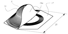
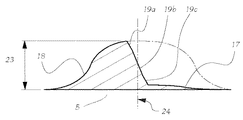
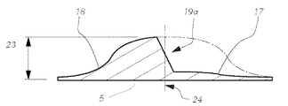
先ず図1について説明するが、図1は、上昇(肉厚)領域(Anstiegsbereich)17と、張出(突出)領域(Auslaufbereich)18と、側面部(傾斜側面部)19aとを有する一構造体要素5の側面断面図を示している。ここでは非図示の照射部により放射された入射光束(光線束)6は、構造体要素5を通過し、出射時には、光線束6の通過部分が上昇領域17から出射するか、張出領域18から出射するか、又は側面部19aから出射するかにより異なって屈折される。この際、全体として、散乱像において重なり合わない3つの異なる光線束7、8、9aが構成される。この際に発生する散乱像は、図2に示されており、図2は、側面部19aを有する構造体要素5の散乱像を示している。この際、光線束7は、修正された第2配光の勾配(明るさ勾配:図2の領域GA)の緩和に寄与し、またこの際、光線束9aにより上述のサインライトが実現される(図2の領域SL)。
First, FIG. 1 will be described. FIG. 1 shows a structure having an ascending (thickness) region (Anstiegsbereich) 17, an overhang (projection) region (Auslaufbereich) 18, and a side surface portion (inclined side surface portion) 19a. A side sectional view of
図1の構造体要素5は、図3〜図5において様々な目視点から図示されている。この際、図3は、六角形の底面10をもち、1つの立上り側面部19aを有する構造体要素5を上から見た図(平面図)を示している。構造体要素5は、構造体要素5の幾何学的な中心点24を通り六角形の底面10の2つの辺を介した対角線(隣接する2つの辺の両端の角を結ぶ対角線)15と平行に延在する線A-Aに関し、鏡面対称に構成されている。図3におけるA-A線に沿った構造体要素5の側面断面図が図4に示されており、この際、上昇領域(台状に上昇した肉厚領域)17が直線的に延在し、張出(突出)領域18が実質的にS字形状で延在し、好ましくはcos関数に類似するかたちで延在していることを見ることができる。また図5は、図3による構造体要素5の斜視図を示している。
The
図6〜図13は、構造体要素5の更なる2つの実施例と、それらに対応する散乱像(図9と図13)に関するものである。
FIGS. 6 to 13 relate to two further embodiments of the
図6は、六角形の底面10をもち、3つの立上り側面部19a、19b、19cを有する構造体要素5を上から見た図を示している。この際、入射光線束の通過時には、5つの異なる光線束が構成される。側面部19aと側面部19cの立上り勾配角は、同じであり、側面部19bの立上り勾配角とは異なっている。このことは、散乱像において、側面部19aにおいて出射する光線束が、側面部19cにおいて出射する光線束と重なり合うことをもたらし、このことは、散乱像においてサインライトの領域SLの光関与分が3つの区域ではなく2つの区域を含んでいるという図9において図示された散乱像から見て取れる。図7は、図6による構造体要素5のB-B線に沿った側面断面図を示しており、この際、前記側面部の異なる立上り勾配角が明確にされている。図8は、図6による構造体要素5の斜視図を示している。
FIG. 6 shows a top view of a
図10は、六角形の底面10をもち、V字形状の立上り側面部19aを有する構造体要素を上から見た図を示している。この際、V字形状の側面部19aは、開角22を有し、V字形状の側面部19aの頂点(エッジ線の中央部)21が、六角形の底面10の幾何学的な中心点と同じである構造体要素5の幾何学的な中心点21に位置しているように構成されている。側面部19aのV字形状により、入射光線束6の出射時には、全体として、異なる空間的な方向へ伝播する4つの出射光線束が構成され、これらは、散乱像において重なり合うことはない。図13におけるサインライトの領域SLへの光関与分は、実質的に、h軸線に対して傾斜した縦長の2つの区域から構成される。構造体要素5のこの実施例において、勾配緩和(明るさ勾配緩和 Gradientenaufweichung)GAのための光関与分は、比較的大きい。
FIG. 10 shows a top view of a structural element having a
図11は、図10による構造体要素5のC-C線に沿った側面断面図を示している。図12は、図10による構造体要素5の斜視図を示している。
FIG. 11 shows a side cross-sectional view along the line CC of the
構造体要素5のこれらの全ての実施例は、例えば、底面10に対する構造体要素5の(突出高さ)最大間隔23や、外周円直径25のような固有値を有する。これらの固有値は、各々、マイクロメートルないしミリメートルの範囲にあり、干渉作用を発生させないために、照射装置により放射される光の典型的な波長と比べて十分に大きい。
All these embodiments of the
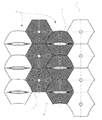
全ての構造体要素は、図14において図示されている六角形の格子13を覆っている。図14における格子(ないし格子構造)13は、格子の規則性からのずれを勿論考えることができるが、正六角形の格子(ないしこれらの集合体)である。構造体要素5、5’(図15参照)の底面10は、格子13の頂点12と頂点12の間にある面11を完全に覆っており、この際、各面(各格子面)11は、正に1つの構造体要素5、5’の底面10により覆われている。更に格子13は、平行に延在する複数の列14、14’に分割して見ることが可能である。そのような列14、14’は、隣り合う複数の面11から成り、1つの面11の2つの辺を介した対角線(隣接する2つの辺の両端の角を結ぶ対角線)15により定義される方向16へ延在している。
All the structural elements cover the
図15は、構造体要素5の底面10が六角形の格子13を2列14’ごと(即ち1列おき)に覆っており、その他の構造体要素5’の底面が六角形の格子13の残った面を覆っているという光学構造体の一実施例を示している。
In FIG. 15, the
更に照射装置2における、構造体要素5、5’から構成される光学構造体1の配設可能性について説明する。
Furthermore, the arrangement | positioning possibility of the optical structure 1 comprised from the
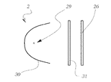
図16は、投射系(投射モジュール)の形式の一照射装置2を模式的に示しており、該照射装置2は、リフレクタ30と、光源29と、(オプションとして)シールド部材(遮光スクリーン部材)32と、湾曲した外面部28及び平坦な内面部を有する投射レンズ27(以下、単に「レンズ27」とも称する)とを備えている。
FIG. 16 schematically shows an
図17は、反射系(反射モジュール)の形式の一照射装置2を模式的に示しており、該照射装置2は、リフレクタ30と、光源29と、拡散ディスクないしカバーディスク26(以下、単に「ディスク26」とも称する)とを備えている。
FIG. 17 schematically shows an
図18は、図16による投射系の模式的な図を示しているが、本発明による光学構造体1がレンズ27の外面部28に配設されている。この際、この光学構造体1は、好ましくはレンズ27の外面部28の全体を覆っている。
FIG. 18 shows a schematic diagram of the projection system according to FIG. 16, but the optical structure 1 according to the present invention is disposed on the
図19は、拡散ディスクないしカバーディスク26の外面部において本発明による光学構造体1を備えた、図17による反射モジュールの模式的な図を示しており、この際、好ましくは、光学構造体1は、ディスク26の外面部の全体を覆っている。
FIG. 19 shows a schematic view of the reflection module according to FIG. 17 with the optical structure 1 according to the invention on the outer surface of a diffusing disc or
図20は、図16に図示された投射モジュールの模式的な図を再度示しているが、ディスク(ないしプレート)のような追加的な光学系要素31として本発明による光学構造体1が備えられており、この際、その光学系要素31は、シールド部材32とレンズ27との間に配設されている。
FIG. 20 again shows a schematic view of the projection module illustrated in FIG. 16, but with the optical structure 1 according to the invention as an additional
最後に図21は、光源29と拡散ディスクないしカバーディスク26との間に配設されているディスクのような追加的な光学系要素31として本発明による光学構造体1を備えた、図17による反射モジュールの模式的な図を示している。
Finally, FIG. 21 is according to FIG. 17 with the optical structure 1 according to the invention as an additional
これらの図は、専ら本発明による光学構造体1の配設構成の可能性の幾つかを具体的に図示するためのものである。基本的に照射装置は、複数の光源を有することも可能であるし、例えば光源としてLEDを有することも可能であり、また光成形体(ライトフォーミングボディ)は、1つ又は複数の光導体やリフレクタなどの形式で構成することも可能である。 These figures are exclusively intended to illustrate some of the possible arrangements of the optical structure 1 according to the invention. Basically, the irradiation device can have a plurality of light sources, for example, can also have an LED as the light source, and the light molded body (light forming body) can be one or more light guides, It is also possible to configure in the form of a reflector or the like.
全般的なこととして、光学構造体1は、照射装置2の全ての光の流れの少なくとも一部分、好ましくは光学的に重要な全ての光の流れが光学構造体1を通過するように、照射装置2に付設されているか又は照射装置2の一部であるということが該当する。
In general, the optical structure 1 is arranged such that at least a part of all light flows of the
特に、光学構造体1が均等に照らされているように、光学構造体1が配設され、及び/又は構成されていると有利である。 In particular, it is advantageous if the optical structure 1 is arranged and / or configured so that the optical structure 1 is evenly illuminated.
最後に、図22及び図23は、非修正の第1配光3及び修正された第2配光4を示している。この際、図22における非修正の第1配光3は、直線的なHD境界を有するロービーム配光3として図示されている。図23における修正された第2配光4は、第1配光3を修正したものであり、本発明による光学構造体1の使用により追加的に発生する2つの領域を含んでいる。即ち勾配緩和(明るさ勾配緩和)の領域GAと、サインライトの領域SLである。
Finally, FIGS. 22 and 23 show an unmodified
図23では、サインライトを発生させるために、HD境界の上側の領域SLがある特定の照射強度で照射されることが見て取れる。この際、照射装置2の光の流れの一部分がこの領域SLへ、即ちHD境界の上側に結像される。このようにして本発明による光学構造体1は、最適の状態で、冒頭に記述したサインライトを発生させることが可能である。
In FIG. 23, it can be seen that the region SL above the HD boundary is irradiated with a certain irradiation intensity in order to generate a sign light. At this time, a part of the light flow of the
HD境界は、非修正の配光のHD境界よりも低い勾配(明るさ勾配)を有し、このことは、明暗境界(HD境界)の領域における等照度線の間隔が(図22のものと比べて)より大きいことにより模式的に示されている。従って修正された第2配光4のHD境界は「よりソフト」(weicher)である。 The HD boundary has a lower gradient (brightness gradient) than the HD boundary of the uncorrected light distribution, which means that the iso-illuminance line interval in the region of the light / dark boundary (HD boundary) is the same as that in FIG. This is schematically shown by being larger. Therefore, the HD boundary of the modified second light distribution 4 is “weicher”.
尚、本発明の全開示(請求の範囲を含む)の枠内において、更にその基本的技術思想に基づいて、実施形態の変更・調整が可能である。また本発明の全開示の枠内において、種々の開示要素(各請求項の各要素、各実施形態の各要素、各図面の各要素等を含む)の多様な組み合わせ、ないし選択が可能である。即ち本発明は、請求の範囲を含む全開示、技術的思想にしたがって当業者であればなし得るであろう各種変形、修正を含むことは勿論である。特に本書に記載した数値範囲については、当該範囲内に含まれる任意の数値ないし小範囲が別段の記載のない場合でも具体的に記載されているものと解釈されるべきである。 It should be noted that, within the scope of the entire disclosure (including claims) of the present invention, the embodiments can be changed and adjusted based on the basic technical concept. Further, various combinations or selections of various disclosed elements (including each element of each claim, each element of each embodiment, each element of each drawing, etc.) are possible within the scope of the entire disclosure of the present invention. . That is, the present invention of course includes various variations and modifications that could be made by those skilled in the art according to the entire disclosure including the claims and the technical concept. In particular, numerical ranges described in this document should be construed as being specifically described even if any numerical value or small range included in the range is not specifically described.
1 光学構造体
2 照射装置
3 非修正の第1配光
4 修正された第2配光
5、5’ 構造体要素
6 入射光束(光線束)
7 光線束(出射)
8 光線束(出射)
9a 光線束(出射)
10 底面
11 格子の頂点の間にある面
12 格子の頂点
13 格子
14、14’ 格子の列
15 対角線(隣接する2つの辺の両端の角を結ぶ対角線)
16 格子の列の方向
17 上昇領域(台状に上昇した肉厚領域)
18 張出領域(突出領域)
19a 側面部(立上り側面部)
19b 側面部(立上り側面部)
19c 側面部(立上り側面部)
20 対角線15と平行な軸線
21 頂点/中心点
22 開角
23 底面に対する最大間隔(又は底面への垂直線)
24 幾何学的な中心点
25 外周円直径(外接円直径)
26 拡散ディスクないしカバーディスク
27 投射レンズ
28 外面部
29 光源
30 リフレクタ
31 光学系要素
32 シールド部材
GA 勾配緩和(明るさ勾配緩和)の領域
SL サインライトの領域
DESCRIPTION OF SYMBOLS 1
7 Light bundle (outgoing)
8 Light bundle (outgoing)
9a Light bundle (outgoing)
10 bottom surface 11
16
18 Overhang area (protruding area)
19a Side surface (rising side surface)
19b Side face (rising side face)
19c Side part (rising side part)
20
24
26 Diffusion disk or
GA Gradient relaxation (brightness gradient relaxation) area SL Sign light area
(関連出願の記載)
本出願は、2015年5月4日出願の欧州特許出願第15166297.0号の優先権主張に基づくものであり、同出願の全記載内容は、引用をもって本明細書に組み込み記載されているものとする。
(Description of related applications)
This application is based on the priority claim of European Patent Application No. 15166297.0 filed on May 4, 2015, the entire content of which is incorporated herein by reference. .
本発明は、特に自動車投光器(例えば前照灯)の照射装置(照明装置)のための光学構造体に関するものである。特に下記の照射装置に用いられるものである。照射装置は、前記照射装置の前方の領域に非修正の第1配光を構成するように光を放射するために配設されており、この際、前記光学構造体は、前記照射装置の全ての光の流れの少なくとも一部分が前記光学構造体を通過するように、前記照射装置に付設されているか又は前記照射装置の一部を成しており、この際、前記照射装置により発生された非修正の配光は、前記光学構造体により、予め設定可能な修正された第2配光に修正されており、この際、前記光学構造体は、2つか3つか又はそれよりも多くの光学的な構造体要素から成り、この際、各構造体要素は、光散乱作用(光拡散作用)を有する。 The present invention particularly relates to an optical structure for an illumination device (illumination device) of an automobile projector (for example, a headlamp). In particular, it is used for the following irradiation apparatus. The irradiation device is arranged to radiate light so as to constitute an uncorrected first light distribution in a region in front of the irradiation device, and at this time, the optical structure is the whole of the irradiation device. Is attached to or forms part of the irradiation device such that at least a part of the light flow passes through the optical structure. The modified light distribution has been modified by the optical structure to a modified second light distribution that can be preset, wherein the optical structure has two, three or more optical distributions. In this case, each structure element has a light scattering action (light diffusion action).
更に本発明は、前記光学構造体を備えた車両投光器用の照射装置に関する。 Furthermore, this invention relates to the irradiation apparatus for vehicle projectors provided with the said optical structure.
更に本発明は、前記照射装置を少なくとも1つ備えた車両投光器に関する。 Furthermore, the present invention relates to a vehicle projector provided with at least one irradiation device.
法的な規程により、車両投光器の配光は、一連の前提条件を満たさなくてはならない。 According to legal regulations, the light distribution of a vehicle floodlight must satisfy a series of prerequisites.
例えばECE(欧州規格)及びSAE(米国規格)により、明暗ライン(HDライン)の上側、即ち主に照射される範囲以外では、所定の領域において最小光度と最大光度が要求される。これらの光度は「サインライト」として機能し、通過する車両からの照射により頭上標識を照らすことを可能にする。使用される光度は、通常、通常の散乱光値を超えるが、HDラインの下側の光度よりも遥かに低い。要求される光値は、眩惑作用ができる限り少ないように達成されなくてはならない。 For example, according to ECE (European standard) and SAE (U.S. standard), the minimum luminous intensity and the maximum luminous intensity are required in a predetermined area except for the upper side of the light and dark line (HD line), that is, the main irradiation range. These luminosities function as “sign lights” and allow overhead signs to be illuminated by illumination from passing vehicles. The luminosity used usually exceeds the normal scattered light value but is much lower than the luminosity below the HD line. The required light value must be achieved so that the dazzling effect is as low as possible.
「サインライト」は、通常、投射レンズにおける特別な小面(ファセット:大きさは少なくとも数ミリメートル)によるか、又は非連続的な小さい隆起部により実現される。この際、特にそれらの構造体が外部から明るい光点として知覚可能であり、従って特に設計上の理由から採用を拒否されることが多いことは、欠点である。更にこの種の装置は、その後方に位置する光学系へ適合されており、それらの装置について変更が行われると、努力して達成された機能は、もはや保証されない。 A “sign light” is usually realized by a special facet (facet: at least a few millimeters in size) in the projection lens or by discontinuous small ridges. In particular, it is a disadvantage that these structures can be perceived as bright light spots from the outside and are therefore often rejected, especially for design reasons. Furthermore, devices of this kind are adapted to the optical systems located behind them, and if changes are made to these devices, the functions achieved with effort are no longer guaranteed.
更に法的な理由から規定された不鮮明な明暗境界が必要とされており、従ってHDラインは、鮮明すぎたりぼやけすぎたりすることなく結像される必要があり、つまりHDラインの最大鮮明度は、法的に規定されている。またHDラインのそのようなぼけは、HDラインが運転者により「ソフト」で且つ主観的により快適に感じられることをもたらしてくれる。 Furthermore, there is a need for blurry light and dark borders defined for legal reasons, so HD lines need to be imaged without being too sharp or too blurry, i.e. the maximum sharpness of the HD line is Is legally stipulated. Such blurring of the HD line also makes the HD line feel “softer” and subjectively more comfortable by the driver.
このHD移行部の定量化は、明暗境界を通る垂直断面に沿った勾配(明るさ勾配)の最大値により行われる。そのために照明強度(照射強度)の対数が(垂直方向の)0.1°間隔の複数の測定点において算出され、それらの差が形成され、それにより勾配関数が得られる。この勾配関数の最大値は、HD境界(明暗境界)の勾配(明るさ勾配)と称される。この定義は、人間の輝度知覚能力を不正確にのみ再現しているので、異なって知覚される複数のHDラインが同じ測定勾配値をもつこともあり、或いは、類似と見える複数のHDラインにおいて異なる勾配が測定されることもある。(尚、本明細書において「°」は、角度表示を表わす。) The quantification of the HD transition portion is performed by the maximum value of the gradient (brightness gradient) along the vertical section passing through the light / dark boundary. For this purpose, the logarithm of the illumination intensity (irradiation intensity) is calculated at a plurality of measurement points at intervals of 0.1 ° (in the vertical direction), and their differences are formed, thereby obtaining a gradient function. The maximum value of this gradient function is referred to as the HD boundary (brightness / darkness boundary) gradient (brightness gradient). This definition only reproduces the human ability to perceive luminance inaccurately, so multiple HD lines that are perceived differently may have the same measured slope value, or in multiple HD lines that appear to be similar. Different slopes may be measured. (In this specification, “°” represents angle display.)
勾配の緩和は、通常、照射装置のレンズのレンズ表面の変更により行われる。従来技術により様々な解決策が一般に用いられている:レンズ表面を統計的に粗面化することにより、例えばよりソフトなHD境界を達成することは可能であるが、それにより対向車の運転者に眩惑(ないし眩しさ Blendung)をもたらすことになる。他のバリエーションでは、変調(モジュレーション:例えば、2つの正弦波の重ね合わせ、球欠の形状の複数の小さな凹部など)がレンズ表面に施される。この種の解決策は、レンズを通る光の流れの分布に強く依存しており、この際、例えば光学技術の変更による光の流れの分布に関する変更は、発生される光の流れの分布に対し、強く且つ部分的にネガティブな影響を及ぼすことになる。 The relaxation of the gradient is usually performed by changing the lens surface of the lens of the irradiation device. Various solutions are commonly used according to the prior art: it is possible to achieve a softer HD boundary, for example, by statistically roughening the lens surface, thereby allowing the driver of the oncoming vehicle Will cause dazzling (or blending). In other variations, modulation (modulation: for example, superposition of two sinusoids, multiple small recesses in the shape of a sphere) is applied to the lens surface. This type of solution relies heavily on the distribution of light flow through the lens, where changes in the light flow distribution, for example due to changes in optical technology, are made with respect to the distribution of light flow generated. A strong and partially negative effect.
従来技術の上述の欠点は、解消されるべきである。従って本発明の課題は、法的な規定値を満たし、同時に不快感を与えることのない、「サインライト」を有する光像(ライトイメージ)を実現可能とする屈折性の光学部材を提供することである。 The above-mentioned drawbacks of the prior art should be overcome. Accordingly, an object of the present invention is to provide a refractive optical member that can realize a light image (light image) having a “sign light” that satisfies legal stipulated values and does not cause discomfort at the same time. It is.
前記課題は、冒頭に記述した光学構造体において、本発明により、複数の構造体要素の第1部分集合部(erste Teilmenge)は、前記構造体要素のこの第1部分集合部へ入射する照射装置により発生された光線束が前記構造体要素の第1部分集合部を通過するように構成されており、各光線束は、各々の前記構造体要素から、第1出射光線束へ、第2出射光線束へ、そして少なくとも1つの更なる出射光線束へ屈折されていることにより解決される。 In the optical structure described at the beginning, according to the present invention, the object is that the first subset portion of the plurality of structure elements is incident on the first subset portion of the structure element. Are configured to pass through a first subset of the structure elements, and each light bundle is transmitted from each of the structure elements to a first output light bundle to a second output. This is solved by being refracted into a light bundle and then into at least one further outgoing light bundle.
即ち本発明の第1の視点により、下記の如き自動車投光器の照射装置のための光学構造体が提供される。前記照射装置は、前記照射装置の前方の領域に非修正の第1配光を構成するように光を放射するために配設されており、前記光学構造体は、前記照射装置の全ての光の流れの少なくとも一部分が前記光学構造体を通過するように、前記照射装置に付設されているか又は前記照射装置の一部を成しており、前記照射装置により発生された非修正の前記第1配光は、前記光学構造体により、予め設定可能な修正された第2配光に修正されており、前記光学構造体は、2つか3つか又はそれよりも多くの光学的な構造体要素から成り、各前記構造体要素は、光散乱作用を有するという形式の光学構造体であり、前記構造体要素の第1部分集合部は、前記構造体要素のこの第1部分集合部へ入射する前記照射装置により発生された光線束が前記構造体要素の前記第1部分集合部を通過するように構成されており、各前記光線束は、各々の前記構造体要素により、第1出射光線束へ、第2出射光線束へ、そして少なくとも1つの更なる出射光線束へ屈折されていることを特徴とする光学構造体が提供される。
更に本発明の第2の視点により、前記光学構造体を少なくとも1つ、或いは正に1つ備えた照射装置が提供される。
更に本発明の第3の視点により、前記照射装置を少なくとも1つ備えた車両投光器が提供される。
尚、本願の特許請求の範囲に付記された図面参照符号は、専ら本発明の理解の容易化のためのものであり、本発明を後続段落で説明する具体的な実施例、特に図示の形態に限定するものではないことを付言する。
That is, according to the first aspect of the present invention, there is provided an optical structure for an illuminating device for an automobile projector as described below. The irradiation device is arranged to emit light so as to constitute an uncorrected first light distribution in a region in front of the irradiation device, and the optical structure includes all light of the irradiation device. The first non-corrected first light generated by the irradiation device is attached to or forms part of the irradiation device so that at least a part of the flow passes through the optical structure. The light distribution is modified by the optical structure to a modified second light distribution that can be set in advance, the optical structure from two, three or more optical structure elements. Each structure element is an optical structure of the type having a light scattering action, and the first subset portion of the structure element is incident on the first subset portion of the structure element. The light beam generated by the irradiation device is the structure. Passing through the first subset of elements, each light bundle being directed to a first outgoing light bundle, a second outgoing light bundle, and at least one by each of the structural elements An optical structure is provided that is refracted into a further outgoing beam.
Further, according to a second aspect of the present invention, there is provided an irradiation apparatus provided with at least one optical structure or just one optical structure.
Furthermore, according to a third aspect of the present invention, there is provided a vehicle projector provided with at least one irradiation device.
It should be noted that reference numerals attached to the claims of the present application are only for facilitating the understanding of the present invention, and specific embodiments, particularly illustrated forms, described in the following paragraphs. It is added that it is not limited to.
本発明の上記第1の視点により、上記課題に対応する効果、即ち法的な規定値を満たし、同時に不快感を与えることのない、「サインライト」を有する光像(ライトイメージ)を実現可能とする屈折性の光学部材が提供される。 According to the first aspect of the present invention, an effect corresponding to the above-mentioned problem, that is, a light image (light image) having a “sign light” that satisfies legal stipulated values and at the same time does not cause discomfort A refractive optical member is provided.
本発明において、以下の形態が可能である。
(形態1)自動車投光器の照射装置のための光学構造体であって、前記照射装置は、前記照射装置の前方の領域に非修正の第1配光を構成するように光を放射するために配設されており、前記光学構造体は、前記照射装置の全ての光の流れの少なくとも一部分が前記光学構造体を通過するように、前記照射装置に付設されているか又は前記照射装置の一部を成しており、前記照射装置により発生された非修正の前記第1配光は、前記光学構造体により、予め設定可能な修正された第2配光に修正されており、前記光学構造体は、2つか3つか又はそれよりも多くの光学的な構造体要素から成り、各前記構造体要素は、光散乱作用を有するという形式の光学構造体であり、前記構造体要素の第1部分集合部は、前記構造体要素のこの第1部分集合部へ入射する前記照射装置により発生された光線束が前記構造体要素の前記第1部分集合部を通過するように構成されており、各前記光線束は、各々の前記構造体要素により、第1出射光線束へ、第2出射光線束へ、そして少なくとも1つの更なる出射光線束へ屈折されていること。
(形態2)前記光学構造体において、前記出射光線束の少なくとも2つは、散乱像において重なり合わないことが好ましい。
(形態3)前記光学構造体において、前記構造体要素の第2部分集合部は、前記構造体要素のこの第2部分集合部へ入射する光が正に1つの光線束のかたちで散乱されているように構成されていることが好ましい。
(形態4)前記光学構造体において、前記構造体要素は、六角形の底面、好ましくは正六角形の底面を有し、つまり前記構造体要素の前記底面は、六角形の格子、好ましくは正六角形の格子を完全に覆っており、前記格子の頂点と頂点の間にある面は、正に1つの前記構造体要素の前記底面により覆われていることが好ましい。
(形態5)前記光学構造体において、前記底面は、正六角形として形成されており、六角形の前記格子は、正六角形の格子として形成されており、正六角形の前記格子は、1つか2つか又はそれよりも多くの平行に延在する列を有し、該列は、前記面のうち1つの面の2つの辺を介した対角線により定義される方向と平行に延在しており、前記構造体要素の前記第1部分集合部における正六角形として形成された前記底面は、各2番目の列を覆っていることが好ましい。
(形態6)前記光学構造体において、前記構造体要素の前記第1部分集合部は、少なくとも、上昇(ないし肉厚)領域と、張出(ないし突出)領域と、1つか2つか又はそれよりも多くの立上り側面部とを有し、前記上昇(ないし肉厚)領域は、各々の前記構造体要素へ入射する前記照射装置により発生された光線束を、第1出射光線束へ屈折し、前記張出(ないし突出)領域は、各々の前記構造体要素へ入射する前記照射装置により発生された光線束を、第2出射光線束へ屈折し、1つか2つか又はそれよりも多くの前記立上り側面部は、各々の前記構造体要素へ入射する前記照射装置により発生された光線束を、少なくとも1つの更なる出射光線束へ屈折することが好ましい。
(形態7)前記光学構造体において、前記上昇(ないし肉厚)領域は、少なくとも1つの前記立上り側面部へ連続的に移行し、及び/又は、少なくとも1つの前記立上り側面部は、前記張出(ないし突出)領域へ連続的に移行することが好ましい。
(形態8)前記光学構造体において、前記構造体要素は、各々、前記構造体要素の幾何学的な中心点を通り2つの辺を介した対角線と平行に延在する軸線に関し、対称に形成され、特に鏡面対称に形成されていることが好ましい。
(形態9)前記光学構造体において、少なくとも1つの前記立上り側面部は、底面と平行な面に沿った前記構造体要素の断面において、実質的にV字形状に形成されていることが好ましい。
(形態10)前記光学構造体において、少なくとも1つの前記立上り側面部は、底面と平行な面に沿った前記構造体要素の断面において、前記構造体要素の幾何学的な中心点を通り2つの辺を介した対角線と平行に延在する軸線に関し、対称に形成され、特に鏡面対称に形成されており、頂点(ないし頂部エッジ線)と開角を有し、該開角は、好ましくは、2°と180°の間か、10°と180°の間か、20°と180°の間か、30°と180°の間か、40°と180°の間か、50°と180°の間か、60°と180°の間か、70°と180°の間か、80°と180°の間か、90°と180°の間か、100°と180°の間か、110°と180°の間か、120°と180°の間か、130°と180°の間か、140°と180°の間か、150°と180°の間か、160°と180°の間か、又は170°と180°の間にあることが好ましい。
(形態11)前記光学構造体において、前記構造体要素は、上昇(ないし肉厚)領域と、張出(ないし突出)領域と、正に1つの立上り側面部とを有し、前記構造体要素の前記上昇領域へ入射する光線束の部分は、第1出射光線束へ屈折されており、該第1出射光線束は、h軸線の下側に散乱されており、前記構造体要素の前記張出領域へ入射する光線束の部分は、第2出射光線束へ屈折されており、該第2出射光線束は、h軸線の上側に散乱されており、前記構造体要素の前記立上り側面部へ入射する光線束の部分は、第3出射光線束へ屈折されており、該第3出射光線束は、h軸線の上側に散乱されており、前記第2出射光線束は、好ましくは、h軸線の上側の0°と3°の間の領域へ散乱されており、前記立上り側面部は、好ましくは、5°と20°の間の範囲内の立上り勾配か、又はほぼ13.8°ないし18.9°の立上り勾配を有し、前記第3出射光線束は、好ましくは、h軸線の上側の2°と4°の間か、4°と5°の間か、又は5°と7°の間の領域へ散乱されていることが好ましい。
(形態12)前記光学構造体において、前記構造体要素は、上昇(ないし肉厚)領域と、張出(ないし突出)領域と、正に3つの立上り側面部とを有し、前記構造体要素の前記上昇領域へ入射する光線束の部分は、第1出射光線束へ屈折されており、該第1出射光線束は、h軸線の下側に散乱されており、前記構造体要素の前記張出領域へ入射する光線束の部分は、第2出射光線束へ屈折されており、該第2出射光線束は、h軸線の上側に散乱されており、前記構造体要素の前記立上り側面部へ入射する光線束の部分は、各々、第3出射光線束と第4出射光線束と第5出射光線束へ屈折されており、これらの出射光線束は、h軸線の上側の領域へ散乱されており、前記第4出射光線束は、散乱像において前記第3出射光線束とも前記第5出射光線束とも重なり合うことはなく、前記第2出射光線束は、好ましくは、h軸線の上側の0°と3°の間の領域へ散乱されており、第1立上り側面部と第3立上り側面部は、好ましくは、8°と12°の間の範囲内の立上り勾配か、又はほぼ10°の立上り勾配を有し、第2立上り側面部は、12°と16°の間の範囲内の立上り勾配か、又はほぼ14°の立上り勾配を有し、前記第3出射光線束と前記第5出射光線束は、好ましくは、h軸線の上側の4°と6°の間の領域へ散乱されており、前記第4出射光線束は、h軸線の上側の6°と8°の間の領域へ散乱されていることが好ましい。
(形態13)前記光学構造体において、前記構造体要素は、上昇(ないし肉厚)領域と、張出(ないし突出)領域と、側面部とを有し、前記側面部は、V字形状に形成されており、頂点(ないし頂部エッジ線)と開角を有し、該頂点は、前記構造体要素の底面の幾何学的な中心点に位置し、前記構造体要素の前記上昇領域へ入射する光線束の部分は、第1出射光線束へ屈折されており、該第1出射光線束は、h軸線の下側に散乱されており、前記構造体要素の前記張出領域へ入射する光線束の部分は、第2出射光線束へ屈折されており、該第2出射光線束は、h軸線の上側に散乱されており、前記構造体要素のV字形状の前記側面部へ入射する光線束の部分は、各々、第3出射光線束と第4出射光線束へ屈折されており、これらの出射光線束は、h軸線の上側の領域へ散乱されており、前記第3出射光線束と前記第4出射光線束は、散乱像において重なり合うことはなく、V字形状の前記側面部は、好ましくは、8°と20°の間の範囲内の立上り勾配か、又はほぼ18.9°の立上り勾配を有し、及び/又は、前記第3出射光線束は、垂直方向において3°と7°の間の領域へ、水平方向において−12°と−7°の間の領域へ散乱されており、及び/又は、前記第4出射光線束は、垂直方向において3°と7°の間の領域へ、水平方向において+7°と+12°の間の領域へ散乱されていることが好ましい。
(形態14)前記光学構造体において、前記構造体要素のサイズ、例えば外周円直径及び/又は底面に対する最大間隔は、可視光の波長よりも大きい、特に遥かに大きいことが好ましい。
(形態15)前記光学構造体において、前記光学構造体は、前記照射装置の拡散ディスクの形式か又はカバーディスクの形式で構成されている光学系要素の少なくとも1つの境界面上、好ましくは正に1つの境界面上に配設されており、及び/又は、前記照射装置のレンズの形式、特に投射レンズの形式の光学系要素の少なくとも1つの表面上に配設されており、及び/又は、前記レンズの光出射面側に配設されていることが好ましい。
(形態16)前記光学構造体において、前記第1出射光線束は、修正された前記第2配光がより低い勾配のHD境界を有するように、非修正の前記第1配光を修正された前記第2配光に修正すること、そして前記更なる出射光線束は、非修正の前記第1配光を修正された前記第2配光に修正して「サインライト」部分配光を構成することが好ましい。
(形態17)前記光学構造体を少なくとも1つ、好ましくは正に1つ備えた照射装置。
(形態18)前記照射装置において、前記照射装置は、投射系であり、前記照射装置は、好ましくは、少なくとも1つの光源と、少なくとも1つのリフレクタと、少なくとも1つのレンズ、特に少なくとも1つの投射レンズとを含んでおり、少なくとも1つの前記光学構造体は、好ましくは、前記レンズ上に配設されており、及び/又は、追加的な光学系要素として構成されていることが好ましい。
(形態19)前記照射装置において、前記照射装置は、反射系であり、前記照射装置は、好ましくは、少なくとも1つのフリーフォームリフレクタと、少なくとも1つの光源と、少なくとも1つの拡散ディスク及び/又は少なくとも1つのカバーディスクとを含んでおり、少なくとも1つの前記光学構造体は、好ましくは、前記少なくとも1つの拡散ディスク上に及び/又は前記少なくとも1つのカバーディスク上に配設されており、及び/又は、追加的な光学系要素として構成されていることが好ましい。
(形態20)前記照射装置を少なくとも1つ備えた車両投光器。
In the present invention, the following modes are possible.
(Embodiment 1) An optical structure for an illuminating device of an automobile projector, wherein the irradiating device emits light so as to constitute an uncorrected first light distribution in a region in front of the irradiating device The optical structure is attached to the irradiation device or a part of the irradiation device so that at least a part of the light flow of all of the irradiation device passes through the optical structure. The uncorrected first light distribution generated by the irradiation device is corrected by the optical structure into a corrected second light distribution that can be set in advance, and the optical structure Consists of two, three or more optical structure elements, each structure element being an optical structure of the type having a light scattering action, the first part of the structure element The assembly portion is the first subset of the structure elements. A beam of light generated by the irradiation device incident on the part passes through the first subset of the structure elements, and each of the beam bundles is generated by the structure element. Refracted into one outgoing beam bundle, into a second outgoing beam bundle and into at least one further outgoing beam bundle.
(Mode 2) In the optical structure, it is preferable that at least two of the emitted light beams do not overlap in the scattered image.
(Mode 3) In the optical structure, in the second subset portion of the structure element, light incident on the second subset portion of the structure element is scattered in the form of exactly one light bundle. It is preferable that it is comprised.
(Form 4) In the optical structure, the structural element has a hexagonal bottom surface, preferably a regular hexagonal bottom surface, that is, the bottom surface of the structural element is a hexagonal lattice, preferably a regular hexagonal shape. It is preferable that the surface of the lattice is completely covered with the bottom surface of one structural element.
(Mode 5) In the optical structure, the bottom surface is formed as a regular hexagon, the hexagonal lattice is formed as a regular hexagonal lattice, and the regular hexagonal lattice is one or two. Or more parallel extending columns, the columns extending parallel to a direction defined by a diagonal line through two sides of one of the surfaces, It is preferable that the bottom surface formed as a regular hexagon in the first subset portion of the structural element covers each second row.
(Mode 6) In the optical structure, the first subset of the structural elements includes at least a rising (or thick) region, an overhanging (or protruding) region, one or two or more thereof. The rising (or thickened) region refracts the light flux generated by the irradiation device incident on each of the structural elements into the first outgoing light flux, The overhanging (or protruding) region refracts the light flux generated by the illuminating device incident on each of the structural elements into a second outgoing light flux, and one, two or more of the The rising side portion preferably refracts the light bundle generated by the irradiation device incident on each of the structural elements into at least one further outgoing light bundle.
(Mode 7) In the optical structure, the rising (or thickening) region continuously transitions to at least one rising side surface portion, and / or at least one rising side surface portion is the overhang. It is preferable to move continuously to the (or protruding) region.
(Mode 8) In the optical structure, each of the structure elements is formed symmetrically with respect to an axis passing through a geometric center point of the structure element and extending parallel to a diagonal line through two sides. In particular, it is preferably formed to be mirror-symmetric.
(Embodiment 9) In the optical structure, it is preferable that at least one rising side surface portion is formed in a substantially V shape in a cross section of the structure element along a plane parallel to the bottom surface.
(Mode 10) In the optical structure, at least one of the rising side surface portions passes through the geometric center point of the structure element in the cross section of the structure element along a plane parallel to the bottom surface, and With respect to an axis extending parallel to the diagonal through the side, it is formed symmetrically, in particular formed mirror-symmetrically and has an apex (or top edge line) and an open angle, which is preferably Between 2 ° and 180 °, between 10 ° and 180 °, between 20 ° and 180 °, between 30 ° and 180 °, between 40 ° and 180 °, or between 50 ° and 180 ° Or between 60 ° and 180 °, between 70 ° and 180 °, between 80 ° and 180 °, between 90 ° and 180 °, between 100 ° and 180 °, 110 Between ° and 180 degrees, between 120 and 180 degrees, between 130 and 180 degrees, or between 140 and 180
(Form 11) In the optical structure, the structure element has an ascending (or thick) region, an overhang (or protruding) region, and exactly one rising side surface portion, and the structure element The portion of the light bundle incident on the rising region is refracted into the first outgoing light bundle, and the first outgoing light bundle is scattered below the h-axis, and the tension of the structural element is The portion of the light bundle incident on the exit area is refracted into the second exit light bundle, and the second exit light bundle is scattered on the upper side of the h-axis, and is directed to the rising side surface portion of the structural element. The portion of the incident light bundle is refracted into a third outgoing light bundle, the third outgoing light bundle is scattered above the h-axis, and the second outgoing light bundle is preferably h-axis Are scattered into a region between 0 ° and 3 ° above, and the rising side is preferably It has a rising slope in the range between 5 ° and 20 °, or a rising slope of approximately 13.8 ° to 18.9 °, and the third exit beam is preferably 2 above the h axis. It is preferably scattered to a region between 0 ° and 4 °, between 4 ° and 5 °, or between 5 ° and 7 °.
(Mode 12) In the optical structure, the structural element has an ascending (or thick) region, an overhanging (or protruding) region, and exactly three rising side surfaces, and the structural element The portion of the light bundle incident on the rising region is refracted into the first outgoing light bundle, and the first outgoing light bundle is scattered below the h-axis, and the tension of the structural element is The portion of the light bundle incident on the exit area is refracted into the second exit light bundle, and the second exit light bundle is scattered on the upper side of the h-axis, and is directed to the rising side surface portion of the structural element. The incident beam bundles are refracted into the third, fourth, and fifth outgoing beam bundles, respectively, and these outgoing beam bundles are scattered to the region above the h-axis. And the fourth outgoing light bundle is the fifth outgoing light beam together with the third outgoing light bundle in the scattered image. The second outgoing light bundle is preferably scattered in a region between 0 ° and 3 ° above the h-axis, and the first rising side surface portion and the third rising side surface portion are not overlapped with the line bundle. And preferably has a rising slope in the range between 8 ° and 12 °, or a rising slope of approximately 10 °, and the second rising side portion has a rising slope in the range between 12 ° and 16 °. Or has a rising slope of approximately 14 °, and the third and fifth outgoing beam bundles are preferably scattered into a region between 4 ° and 6 ° above the h-axis. The fourth outgoing light bundle is preferably scattered in a region between 6 ° and 8 ° above the h-axis.
(Form 13) In the optical structure, the structure element has a rising (or thick) region, an overhanging (or protruding) region, and a side surface, and the side surface has a V-shape. Formed and having an apex (or top edge line) and an open angle, the apex being located at the geometric center point of the bottom surface of the structure element and incident on the rising region of the structure element The portion of the light bundle that is refracted into the first outgoing light bundle, the first outgoing light bundle being scattered below the h-axis line, and the light incident on the protruding region of the structural element The portion of the bundle is refracted into the second outgoing light bundle, and the second outgoing light bundle is scattered on the upper side of the h-axis, and is incident on the V-shaped side surface portion of the structural element. The portions of the bundle are refracted into the third and fourth outgoing light bundles, respectively. , The third outgoing beam bundle and the fourth outgoing beam bundle do not overlap in the scattered image, and the V-shaped side surface portion is preferably 8 °. And a rising slope in the range between 20 ° and 20 °, or a rising slope of approximately 18.9 °, and / or the third outgoing beam bundle is a region between 3 ° and 7 ° in the vertical direction To the region between −12 ° and −7 ° in the horizontal direction and / or the fourth outgoing beam bundle is horizontally directed to the region between 3 ° and 7 ° in the vertical direction. Is preferably scattered to a region between + 7 ° and + 12 °.
(Embodiment 14) In the optical structure, it is preferable that the size of the structure element, for example, the outer circumferential circle diameter and / or the maximum distance from the bottom surface is larger than the wavelength of visible light, particularly much larger.
(Mode 15) In the optical structure, the optical structure is preferably on the boundary surface of at least one optical element configured in the form of a diffusion disk or a cover disk of the irradiation device, preferably positively. Arranged on one interface and / or arranged on at least one surface of an optical element in the form of a lens of the illumination device, in particular a projection lens, and / or It is preferable that the lens is disposed on the light exit surface side of the lens.
(Mode 16) In the optical structure, the first light beam bundle is modified from the unmodified first light distribution so that the modified second light distribution has a lower gradient HD boundary. Modifying to the second light distribution, and the further outgoing beam bundle modifies the unmodified first light distribution to the modified second light distribution to form a “sign light” section light distribution It is preferable.
(Mode 17) An irradiation apparatus provided with at least one, preferably just one optical structure.
(Mode 18) In the irradiation apparatus, the irradiation apparatus is a projection system, and the irradiation apparatus is preferably at least one light source, at least one reflector, at least one lens, particularly at least one projection lens. The at least one optical structure is preferably disposed on the lens and / or is configured as an additional optical component.
(Mode 19) In the irradiation apparatus, the irradiation apparatus is a reflection system, and the irradiation apparatus is preferably at least one free-form reflector, at least one light source, at least one diffusion disk, and / or at least And at least one optical structure is preferably disposed on the at least one diffusion disk and / or on the at least one cover disk, and / or It is preferable to be configured as an additional optical system element.
(Mode 20) A vehicle projector provided with at least one irradiation device.
照射装置により発生される上述の光像は、個々の構造体要素の散乱像(拡散像)の重ね合わせとして構成される。この際、個々の構造体要素の散乱像は、構造体要素を通過した光により発生される。 The above-described optical image generated by the irradiation device is configured as a superposition of scattered images (diffuse images) of individual structure elements. At this time, a scattered image of each structure element is generated by light that has passed through the structure element.
散乱像内の異なる領域は、出射光線束の少なくとも2つが散乱像において重なり合わないものとして照らされる。 Different regions in the scatter image are illuminated as those where at least two of the outgoing beam bundles do not overlap in the scatter image.
この際、構造体要素(複数)の第2部分集合部(zweite Teilmenge)は、この第2部分集合部の構造体要素へ入射する光が正に1つの光線束のかたちで散乱されているように構成されている。 At this time, the second subset part (zweite Teilmenge) of the structural element (s) seems to have the light incident on the structural element of the second partial part scattered in the form of exactly one light bundle. It is configured.
この際、構造体要素(複数)の第2部分集合部が空(leer)であり(即ち第2部分集合部を構成する構造体要素がないということ)、光学構造体が第1部分集合部の構造体要素からのみ構成されていることも勿論可能である。第2部分集合部の大きさは、例えば、どのくらいの光が上述の更なる出射光線束の形式で散乱されなくてはならないかに依存することができる。 At this time, the second subset of the structural element (s) is empty (that is, there is no structural element constituting the second partial subset), and the optical structure is the first partial subset. Of course, it is also possible to comprise only the structural elements. The size of the second subset can depend, for example, on how much light must be scattered in the form of the further outgoing beam bundle described above.
光学構造体の製造は、構造体要素が、六角形の底面、好ましくは正六角形の底面を有すると比較的容易に自動化することが可能であり、つまり構造体要素の底面は、六角形の格子、好ましくは正六角形の格子を完全に覆っており、格子の頂点(複数)の間にある面は、正に1つの構造体要素の底面により覆われている。 The production of the optical structure can be automated relatively easily if the structure element has a hexagonal bottom surface, preferably a regular hexagonal bottom surface, i.e. the bottom surface of the structure element is a hexagonal lattice. , Preferably completely covering the regular hexagonal grid, the plane lying between the apexes of the grid being covered by the bottom of exactly one structural element.
この場合、底面が正六角形として形成されており、六角形の格子が正六角形の格子として形成されており、正六角形の格子が、1つか2つか又はそれよりも多くの平行に延在する列を有し、該列が、面(格子面)のうち1つの面の2つの辺を介した対角線により定義される方向と平行に延在すると有利であり得て、この際、構造体要素の第1部分集合部における正六角形として形成された底面は、各2番目の列を覆っている。 In this case, the bottom surface is formed as a regular hexagon, the hexagonal lattice is formed as a regular hexagonal lattice, and the regular hexagonal lattice is one, two or more parallel extending columns. And the rows extend in parallel with the direction defined by the diagonals through the two sides of one of the planes (lattice planes), in which case The bottom surface formed as a regular hexagon in the first subset portion covers each second row.
光像内のサインライト領域を最適に照らすためには、構造体要素の第1部分集合部は(各々の構造体要素について)少なくとも、上昇領域(台状に上昇した肉厚領域 Anstiegsbereich)と、張出(突出)領域(Auslaufbereich)と、1つか2つか又はそれよりも多くの立上り側面部(ansteigende Flanke)とを有すると有利であり得て、この際、上昇領域は、各々の構造体要素へ入射する照射装置により発生された光線束を、第1出射光線束へ屈折し、張出領域は、各々の構造体要素へ入射する照射装置により発生された光線束を、第2出射光線束へ屈折し、1つか2つか又はそれよりも多くの立上り側面部は、各々の構造体要素へ入射する照射装置により発生された光線束を、少なくとも1つの更なる出射光線束へ屈折する。 In order to optimally illuminate the sine light region in the light image, the first subset of structure elements (for each structure element) is at least a raised region (thickened region Anstiegsbereich raised in a trapezoidal shape), It may be advantageous to have an overhanging area (Auslaufbereich) and one, two or more rising sides (ansteigende Flanke), in which case the rising area will be in each structural element The beam bundle generated by the irradiating device entering the beam is refracted into the first outgoing beam bundle, and the overhanging region converts the beam bundle generated by the irradiating device entering each structural element into the second outgoing beam bundle. One, two or more rising side surfaces refract the light bundles generated by the illumination device incident on each structure element into at least one further outgoing light bundle.
この際、上昇領域は、実質的に直線的な延在経過を有し、及び/又は、張出領域は、実質的にS字形状の延在経過、好ましくはcos関数に類似の延在経過を有することを考慮することができる。 In this case, the rising region has a substantially linear extension process and / or the overhang region has a substantially S-shaped extension process, preferably an extension process similar to the cos function. Can be considered.
それに加え、製造のためには、上昇領域が少なくとも1つの立上り側面部へ連続的に移行し、及び/又は、少なくとも1つの立上り側面部が張出領域へ連続的に移行すると特に有利である。 In addition, it is particularly advantageous for manufacturing if the rising region continuously transitions to at least one rising side and / or at least one rising side continuously transitions to the overhanging region.
更に構造体要素が、各々、構造体要素の幾何学的な中心点を通り2つの辺を介した対角線(2つの隣接した辺の両端の角を結ぶ対角線)と平行に延在する軸線に関し、対称に形成され、特に鏡面対称に形成されていると有利である。 Furthermore, each axis of the structure element extends in parallel with a diagonal line passing through the geometric center point of the structure element and passing through two sides (a diagonal line connecting the corners of both ends of two adjacent sides). It is advantageous if they are formed symmetrically, in particular mirror-symmetrically.
本発明の特に有利な一実施形態においては、少なくとも1つの立上り側面部が、底面と平行な面に沿った構造体要素の断面において、実質的にV字形状に形成されていることが考慮されている。 In a particularly advantageous embodiment of the invention, it is considered that at least one rising side surface is formed in a substantially V-shape in the cross section of the structural element along a plane parallel to the bottom surface. ing.
少なくとも1つの立上り側面部が、底面と平行な面に沿った構造体要素の断面において、構造体要素の幾何学的な中心点を通り2つの辺を介した対角線と平行に延在する軸線に関し、対称に形成され、特に鏡面対称に形成されており、頂点(ないし頂部エッジ線)と開角を有することを考慮することができる。 An axis with at least one rising side surface extending in a cross section of the structure element along a plane parallel to the bottom surface, passing through the geometric center point of the structure element and parallel to a diagonal line through two sides It can be considered that it is formed symmetrically, in particular, mirror-symmetrically, and has an apex (or top edge line) and an open angle.
2つの立上り側面部の間の開角(Oeffnungswinkel)が、2°と180°の間か、10°と180°の間か、20°と180°の間か、30°と180°の間か、40°と180°の間か、50°と180°の間か、60°と180°の間か、70°と180°の間か、80°と180°の間か、90°と180°の間か、100°と180°の間か、110°と180°の間か、120°と180°の間か、130°と180°の間か、140°と180°の間か、150°と180°の間か、160°と180°の間か、又は170°と180°の間にあると有利である。 Whether the opening angle (Oeffnungswinkel) between the two rising sides is between 2 ° and 180 °, between 10 ° and 180 °, between 20 ° and 180 °, or between 30 ° and 180 ° Between 40 ° and 180 °, between 50 ° and 180 °, between 60 ° and 180 °, between 70 ° and 180 °, between 80 ° and 180 °, or between 90 ° and 180 ° Between 100 ° and 180 °, between 110 ° and 180 °, between 120 ° and 180 °, between 130 ° and 180 °, between 140 ° and 180 °, Advantageously, it is between 150 ° and 180 °, between 160 ° and 180 °, or between 170 ° and 180 °.
同様に本発明による光学構造体は、照射装置により放射された光を、減光(防眩)された配光の形式、特にロービーム配光の形式で結像するように配設されている照射装置にとって有利であり、この際、減光された配光、特にロービーム配光は、HD境界を有し、この際、本発明により、照射装置の光の流れの一部分がHD境界の上側の所定の領域へ結像されるように、光学構造体、特に構造体要素が形成されている。 Similarly, the optical structure according to the invention is arranged so that the light emitted by the irradiation device is imaged in the form of a dimmed (anti-glare) light distribution, in particular in the form of a low beam light distribution. The apparatus is advantageous, in which a dimmed light distribution, in particular a low beam light distribution, has an HD boundary, wherein according to the invention a part of the light flow of the illuminating device is pre-determined above the HD boundary. An optical structure, in particular a structural element, is formed so as to be imaged in the region.
このようにして本発明による光学構造体を用い、例えば各光学的な構造体要素が、この構造体要素を通過する光の流れの僅かな部分を対応する所定の領域へ偏向させることにより、冒頭に記述したサインライトを最適の状態で発生させることが可能である。この際、水平線(h軸線)と垂直線(v軸線)を有する直交座標系が定義されている散乱像において、個々の出射光線束の偏向角度を観察することは、目的に適っている。 In this way, using the optical structure according to the invention, for example, each optical structure element starts by deflecting a small part of the flow of light passing through the structure element to a corresponding predetermined area. It is possible to generate the sign light described in the above in an optimal state. At this time, it is suitable for the purpose to observe the deflection angle of each outgoing ray bundle in a scattered image in which an orthogonal coordinate system having a horizontal line (h-axis line) and a vertical line (v-axis line) is defined.
本発明の具体的な一実施形態において、構造体要素は、上昇領域と、張出領域と、正に1つの立上り側面部とを有することが考慮されており、この際、構造体要素の上昇領域へ入射する光線束の部分は、第1出射光線束へ屈折されており、該第1出射光線束は、h軸線の下側に散乱されており、構造体要素の張出領域へ入射する光線束の部分は、第2出射光線束へ屈折されており、該第2出射光線束は、h軸線の上側に散乱されており、構造体要素の立上り側面部へ入射する光線束の部分は、第3出射光線束へ屈折されており、該第3出射光線束は、h軸線の上側に散乱されている。 In a specific embodiment of the invention, it is considered that the structural element has a rising area, an overhang area and exactly one rising side surface, in which case the rising of the structural element The portion of the light beam incident on the region is refracted into the first output light beam, and the first output light beam is scattered below the h-axis and enters the protruding region of the structural element. The portion of the light bundle is refracted into the second outgoing light bundle, the second outgoing light bundle is scattered above the h-axis, and the portion of the light bundle incident on the rising side surface portion of the structural element is , And is refracted into a third outgoing light bundle, which is scattered above the h-axis.
この際、第2出射光線束がh軸線の上側の0°と3°の間の領域へ散乱されていると目的に適うと分かった。 At this time, it has been found that the second emitted light beam is suitable for the purpose if it is scattered in a region between 0 ° and 3 ° above the h-axis.
出射光線束の所望の偏向を保証するために、立上り側面部が5°と20°の間の範囲内の立上り勾配(所定の屈折・散乱を生ずる立上り勾配)か、又はほぼ13.8°ないし18.9°の立上り勾配を有し、第3出射光線束がh軸線の上側の2°と4°の間か、4°と5°の間か、又は5°と7°の間の領域へ散乱されていると目的に適っている。尚、立上り勾配の角度は、底面に対し、規定できる。 In order to guarantee the desired deflection of the outgoing beam, the rising side is either rising in the range between 5 ° and 20 ° (rising gradient causing a given refraction / scattering) or approximately 13.8 ° to A region having a rising slope of 18.9 ° and the third output beam bundle being between 2 ° and 4 ° above the h-axis, between 4 ° and 5 °, or between 5 ° and 7 ° It is suitable for the purpose if it is scattered. The angle of the rising slope, against the bottom surface, can be defined.
本発明の具体的な更なる一実施形態において、構造体要素は、上昇領域と、張出領域と、正に3つの立上り側面部とを有することを考慮することができ、この際、構造体要素の上昇領域へ入射する光線束の部分は、第1出射光線束へ屈折されており、該第1出射光線束は、h軸線の下側に散乱されており、構造体要素の張出領域へ入射する光線束の部分は、第2出射光線束へ屈折されており、該第2出射光線束は、h軸線の上側に散乱されており、構造体要素の立上り側面部へ入射する光線束の部分は、各々、第3出射光線束と第4出射光線束と第5出射光線束へ屈折されており、この際、これらの出射光線束は、h軸線の上側の領域へ散乱されており、第4出射光線束は、散乱像において第3出射光線束とも第5出射光線束とも重なり合わない。 In a further specific embodiment of the invention, it can be considered that the structure element has a rising area, an overhang area and exactly three rising side parts, wherein the structure The part of the light beam incident on the rising region of the element is refracted into the first outgoing light beam, which is scattered below the h-axis, and the projecting region of the structural element The portion of the light bundle incident on the light beam is refracted into the second outgoing light bundle, and the second outgoing light bundle is scattered on the upper side of the h-axis and is incident on the rising side surface portion of the structural element. Are refracted into the third, fourth, and fifth outgoing beam bundles, and these outgoing beam bundles are scattered to the region above the h-axis. The fourth outgoing light bundle overlaps with the third outgoing light bundle and the fifth outgoing light bundle in the scattered image. There.
この際、第2出射光線束がh軸線の上側の0°と3°の間の領域へ散乱されていると目的に適っている(好都合である)。 At this time, it is suitable (convenient) if the second outgoing light beam is scattered in a region between 0 ° and 3 ° above the h-axis.
それに加え、第1立上り側面部と第3立上り側面部が8°と12°の間の範囲内の立上り勾配(所定の屈折・散乱を生じる立上り勾配)か、又はほぼ10°の立上り勾配を有し、第2立上り側面部が12°と16°の間の範囲内の立上り勾配か、又はほぼ14°の立上り勾配を有し、第3出射光線束と第5出射光線束がh軸線の上側の4°と6°の間の領域へ散乱されており、第4出射光線束がh軸線の上側の6°と8°の間の領域へ散乱されていると目的に適っている。 In addition, the first rising side surface portion and the third rising side surface portion have a rising gradient within a range between 8 ° and 12 ° (a rising gradient that causes predetermined refraction and scattering), or a rising gradient of approximately 10 °. And the second rising side surface portion has a rising slope within a range between 12 ° and 16 °, or a rising slope of approximately 14 °, and the third and fifth outgoing light bundles are above the h-axis. It is suitable for the purpose that it is scattered in the region between 4 ° and 6 ° of the first and the fourth outgoing light beam is scattered in the region between 6 ° and 8 ° above the h-axis.
更に構造体要素は、上昇領域と、張出領域と、側面部(傾斜側面部)とを有することが考慮されており、この際、側面部は、V字形状に形成されており、頂点と開角を有し、頂点は、構造体要素の底面の幾何学的な中心点に位置し、この際、構造体要素の上昇領域へ入射する光線束の部分は、第1出射光線束へ屈折されており、該第1出射光線束は、h軸線の下側に散乱されており、構造体要素の張出領域へ入射する光線束の部分は、第2出射光線束へ屈折されており、該第2出射光線束は、h軸線の上側に散乱されており、構造体要素のV字形状の側面部へ入射する光線束の部分は、各々、第3出射光線束と第4出射光線束へ屈折されており、この際、これらの出射光線束は、h軸線の上側の領域へ散乱されており、第3出射光線束と第4出射光線束は、散乱像において重なり合わない。 Further, the structure element is considered to have a rising region, an overhang region, and a side surface portion (inclined side surface portion). At this time, the side surface portion is formed in a V shape, With an open angle, the apex being located at the geometric center point of the bottom surface of the structure element, where the portion of the light beam incident on the ascending region of the structure element is refracted into the first output light beam The first outgoing light bundle is scattered below the h axis, and the portion of the light bundle incident on the overhanging region of the structure element is refracted into the second outgoing light bundle, The second outgoing light bundle is scattered on the upper side of the h-axis, and the portions of the light bundle incident on the V-shaped side surface portion of the structure element are the third outgoing light bundle and the fourth outgoing light bundle, respectively. At this time, these outgoing beam bundles are scattered to the region above the h-axis, and the third outgoing beam bundle and the fourth Shako ray flux, do not overlap in the scattering image.
この際、有利には、V字形状の側面部が8°と20°の間の範囲内の立上り勾配(所定の屈折・散乱を生じる立上り勾配)か、又はほぼ18.9°の立上り勾配を有し、第3出射光線束が垂直方向において3°と7°の間の領域へ、水平方向において−12°と−7°の間の領域へ散乱されており、第4出射光線束が垂直方向において3°と7°の間の領域へ、水平方向において+7°と+12°の間の領域へ散乱されていることが考慮されている。 In this case, it is advantageous that the V-shaped side part has a rising slope in the range between 8 ° and 20 ° (a rising slope that produces a predetermined refraction / scattering) or a rising slope of approximately 18.9 °. And the third outgoing light bundle is scattered into a region between 3 ° and 7 ° in the vertical direction and into a region between −12 ° and −7 ° in the horizontal direction, and the fourth outgoing light bundle is vertical. It is considered that the light is scattered to a region between 3 ° and 7 ° in the direction and to a region between + 7 ° and + 12 ° in the horizontal direction.
また構造体要素が、それらの底面の幾何学的な中心点において底面に対してそれらの最大間隔を有すると有利である。 It is also advantageous if the structural elements have their maximum spacing relative to the bottom surface at the geometric center point of their bottom surface.
干渉作用を回避するために、構造体要素のサイズ、例えば外周円直径(Umkreisdurchmesser)及び/又は底面に対する最大間隔が、可視光の波長よりも大きい、特に遥かに大きいと有利である。 In order to avoid interference effects, it is advantageous if the size of the structure element, for example the circumference diameter (Umkreisdurchmesser) and / or the maximum distance to the bottom, is greater than the wavelength of visible light, in particular far greater.
この際、具体的には、底面に対する最大間隔がマイクロメートルの領域(オーダ)にあることを考慮することができる。 At this time, specifically, it can be considered that the maximum distance to the bottom surface is in a micrometer region (order).
この際、底面に対する最大間隔は、5〜10マイクロメートルの範囲内か、10〜13マイクロメートルの範囲内か、13〜17マイクロメートルの範囲内か、ほぼ9.3マイクロメートルか、ほぼ10.6マイクロメートルか、ほぼ12.15マイクロメートルか、又はほぼ16.6マイクロメートルであると有利である。 In this case, the maximum distance to the bottom surface is in the range of 5 to 10 micrometers, in the range of 10 to 13 micrometers, in the range of 13 to 17 micrometers, approximately 9.3 micrometers, or approximately 10. Advantageously, it is 6 micrometers, approximately 12.15 micrometers, or approximately 16.6 micrometers.
本発明の具体的な一実施形態において、構造体要素の外周円直径ないし長さは、ミリメートルの領域(オーダ)にあることが考慮されている。 In a specific embodiment of the invention, it is considered that the outer circumferential diameter or length of the structural element is in the millimeter range (order).
この際、構造体要素の直径ないし長さが、0.5〜2ミリメートルか、ほぼ1ミリメートルであると有利であり得る。 In this case, it may be advantageous if the diameter or length of the structural element is between 0.5 and 2 millimeters or approximately 1 millimeter.
好ましくは、光学構造体は、照射装置の拡散ディスク(散乱ディスク Streuscheibe)の形式か又はカバーディスクの形式で構成されている光学系要素の少なくとも1つの境界面上、好ましくは正に1つの境界面上に配設されていることが考慮されている。 Preferably, the optical structure is on at least one interface of an optical element, preferably in the form of a diffuser disk (scattering disk Streuscheibe) of the irradiator or in the form of a cover disk, preferably just one interface. It is considered that it is disposed above.
本発明の具体的な一実施形態において、光学構造体は、照射装置のレンズの形式、特に投射レンズの形式の光学系要素の少なくとも1つの表面上に配設されていることを考慮することができる。 In a specific embodiment of the invention, it may be considered that the optical structure is arranged on at least one surface of an optical element in the form of a lens of the illumination device, in particular in the form of a projection lens. it can.
それに加え、光学構造体が前記レンズの光出射面側に配設されていると、特に有利である。 In addition, it is particularly advantageous if the optical structure is arranged on the light exit surface side of the lens.
全ての光の流れからある1つの所定の(非修正の)光束を見た場合、該光束は、光像内の配光に対してある特定の寄与分を構成する(全ての光の流れが(全)配光を発生させている)。例えば非修正の光束は、ある所定の形状を伴う配光寄与分を発生させ、即ち路面上又は測定スクリーン上では、所定の領域が照射され、その他の領域は照射されていない(即ち明の領域と暗の領域を形成する)。 If one predetermined (uncorrected) light beam is seen from all light flows, the light beam constitutes a certain contribution to the light distribution in the light image (all light flows are (All) light distribution is generated). For example, an uncorrected luminous flux generates a light distribution contribution with a certain predetermined shape, that is, a predetermined area is irradiated on the road surface or the measurement screen, and other areas are not irradiated (that is, a bright area). And form a dark area).
本発明の具体的な一実施形態において、第1出射光線束は、非修正の第1配光を修正された第2配光に修正し、それにより修正された第2配光は、より低い勾配(明るさ勾配)のHD境界を有する。 In a specific embodiment of the present invention, the first outgoing beam bundle modifies the unmodified first light distribution into a modified second light distribution, whereby the modified second light distribution is lower. It has a gradient (brightness gradient) HD boundary.
この際、更なる出射光線束(1つ以上)が、非修正の第1配光を修正された第2配光に修正して「サインライト」部分配光を構成すると目的に適うことができる。 At this time, it is possible to satisfy the purpose by further configuring the “sign light” portion distribution light by modifying the uncorrected first light distribution to the corrected second light distribution by further emitting light beam bundle (s). .
また最終的に本発明は、上述の光学構造体を少なくとも1つ、好ましくは正に1つ備えた照射装置(照明装置)に関する。 Further, the present invention finally relates to an irradiation apparatus (illumination apparatus) provided with at least one, preferably just one, of the optical structure described above.
例えば、照射装置は、投射系(投射システム Projektionssystem)である。 For example, the irradiation apparatus is a projection system (projection system Projektions system).
この場合、好ましくは、照射装置は、少なくとも1つの光源と、少なくとも1つのリフレクタ(反射器)と、少なくとも1つのレンズ、特に少なくとも1つの投射レンズとを含んでいることが考慮されている。 In this case, preferably, it is considered that the illumination device comprises at least one light source, at least one reflector (reflector), and at least one lens, in particular at least one projection lens.
この際、少なくとも1つの前記光学構造体が、前記レンズ上に配設されており、及び/又は、追加的な光学系要素として構成されていると有利であり得る。 In this case, it may be advantageous if at least one of the optical structures is arranged on the lens and / or is configured as an additional optical system element.
しかしまた、照射装置が反射系(反射システム Reflexionssystem)であることも考慮することができる。 However, it can also be taken into account that the irradiation device is a reflection system.
この場合、照射装置は、少なくとも1つのフリーフォームリフレクタ(自由形式反射器)と、少なくとも1つの光源と、少なくとも1つの拡散ディスク及び/又は少なくとも1つのカバーディスクとを含んでいると目的に適うと分かった。 In this case, if the irradiation device includes at least one free-form reflector (free-form reflector), at least one light source, at least one diffusion disk and / or at least one cover disk, it is suitable for the purpose. I understood.
この際、少なくとも1つの前記光学構造体が、前記少なくとも1つの拡散ディスク上に及び/又は前記少なくとも1つのカバーディスク上に配設されており、及び/又は、追加的な光学系要素として構成されていると有利である。 In this case, at least one of the optical structures is arranged on the at least one diffusion disk and / or on the at least one cover disk and / or is configured as an additional optical system element. It is advantageous to have.
以下、本発明を、有利であり限定されない実施例に基づき更に詳細に説明するが、これらの実施例は、3つの構成形態における構造体要素に関するものであり、添付の各々の図面に図示されている。尚、以下の実施例は、本発明の理解の容易化のためのものであって、本発明の技術的思想を逸脱しない範囲において、当業者により実施可能な付加や置換、開示された各要素の選択ないし選択的組合せ等を排除することを意図するものではない。 The invention will now be described in more detail on the basis of advantageous and non-limiting examples, which relate to structural elements in three configurations and are illustrated in the accompanying drawings. Yes. The following examples are for facilitating the understanding of the present invention, and within the scope of the technical idea of the present invention, additions, substitutions, and disclosed elements that can be implemented by those skilled in the art. It is not intended to exclude the selection or selective combination.
先ず図1について説明するが、図1は、上昇(肉厚)領域(Anstiegsbereich)17と、張出(突出)領域(Auslaufbereich)18と、側面部(傾斜側面部)19aとを有する一構造体要素5の側面断面図を示している。ここでは非図示の照射部により放射された入射光束(光線束)6は、構造体要素5を通過し、出射時には、光線束6の通過部分が上昇領域17から出射するか、張出領域18から出射するか、又は側面部19aから出射するかにより異なって屈折される。この際、全体として、散乱像において重なり合わない3つの異なる光線束7、8、9aが構成される。この際に発生する散乱像は、図2に示されており、図2は、側面部19aを有する構造体要素5の散乱像を示している。この際、光線束7は、修正された第2配光の勾配(明るさ勾配:図2の領域GA)の緩和に寄与し、またこの際、光線束9aにより上述のサインライトが実現される(図2の領域SL)。
First, FIG. 1 will be described. FIG. 1 shows a structure having an ascending (thickness) region (Anstiegsbereich) 17, an overhang (projection) region (Auslaufbereich) 18, and a side surface portion (inclined side surface portion) 19a. A side sectional view of
図1の構造体要素5は、図3〜図5において様々な目視点から図示されている。この際、図3は、六角形の底面10をもち、1つの立上り側面部19aを有する構造体要素5を上から見た図(平面図)を示している。構造体要素5は、構造体要素5の幾何学的な中心点24を通り六角形の底面10の2つの辺を介した対角線(隣接する2つの辺の両端の角を結ぶ対角線)15と平行に延在する線A-Aに関し、鏡面対称に構成されている。図3におけるA-A線に沿った構造体要素5の側面断面図が図4に示されており、この際、上昇領域(台状に上昇した肉厚領域)17が直線的に延在し、張出(突出)領域18が実質的にS字形状で延在し、好ましくはcos関数に類似するかたちで延在していることを見ることができる。また図5は、図3による構造体要素5の斜視図を示している。
The
図6〜図13は、構造体要素5の更なる2つの実施例と、それらに対応する散乱像(図9と図13)に関するものである。
FIGS. 6 to 13 relate to two further embodiments of the
図6は、六角形の底面10をもち、3つの立上り側面部19a、19b、19cを有する構造体要素5を上から見た図を示している。この際、入射光線束の通過時には、5つの異なる光線束が構成される。側面部19aと側面部19cの立上り勾配角は、同じであり、側面部19bの立上り勾配角とは異なっている。このことは、散乱像において、側面部19aにおいて出射する光線束が、側面部19cにおいて出射する光線束と重なり合うことをもたらし、このことは、散乱像においてサインライトの領域SLの光関与分が3つの区域ではなく2つの区域を含んでいるという図9において図示された散乱像から見て取れる。図7は、図6による構造体要素5のB-B線に沿った側面断面図を示しており、この際、前記側面部の異なる立上り勾配角が明確にされている。図8は、図6による構造体要素5の斜視図を示している。
FIG. 6 shows a top view of a
図10は、六角形の底面10をもち、V字形状の立上り側面部19aを有する構造体要素を上から見た図を示している。この際、V字形状の側面部19aは、開角22を有し、V字形状の側面部19aの頂点(エッジ線の中央部)21が、六角形の底面10の幾何学的な中心点と同じである構造体要素5の幾何学的な中心点21に位置しているように構成されている。側面部19aのV字形状により、入射光線束6の出射時には、全体として、異なる空間的な方向へ伝播する4つの出射光線束が構成され、これらは、散乱像において重なり合うことはない。図13におけるサインライトの領域SLへの光関与分は、実質的に、h軸線に対して傾斜した縦長の2つの区域から構成される。構造体要素5のこの実施例において、勾配緩和(明るさ勾配緩和 Gradientenaufweichung)GAのための光関与分は、比較的大きい。
FIG. 10 shows a top view of a structural element having a
図11は、図10による構造体要素5のC-C線に沿った側面断面図を示している。図12は、図10による構造体要素5の斜視図を示している。
FIG. 11 shows a side cross-sectional view along the line CC of the
構造体要素5のこれらの全ての実施例は、例えば、底面10に対する構造体要素5の(突出高さ)最大間隔23や、外周円直径25のような固有値を有する。これらの固有値は、各々、マイクロメートルないしミリメートルの範囲にあり、干渉作用を発生させないために、照射装置により放射される光の典型的な波長と比べて十分に大きい。
All these embodiments of the
全ての構造体要素は、図14において図示されている六角形の格子13を覆っている。図14における格子(ないし格子構造)13は、格子の規則性からのずれを勿論考えることができるが、正六角形の格子(ないしこれらの集合体)である。構造体要素5、5’(図15参照)の底面10は、格子13の頂点12と頂点12の間にある面11を完全に覆っており、この際、各面(各格子面)11は、正に1つの構造体要素5、5’の底面10により覆われている。更に格子13は、平行に延在する複数の列14、14’に分割して見ることが可能である。そのような列14、14’は、隣り合う複数の面11から成り、1つの面11の2つの辺を介した対角線(隣接する2つの辺の両端の角を結ぶ対角線)15により定義される方向16へ延在している。
All the structural elements cover the
図15は、構造体要素5の底面10が六角形の格子13を2列14’ごと(即ち1列おき)に覆っており、その他の構造体要素5’の底面が六角形の格子13の残った面を覆っているという光学構造体の一実施例を示している。
In FIG. 15, the
更に照射装置2における、構造体要素5、5’から構成される光学構造体1の配設可能性について説明する。
Furthermore, the arrangement | positioning possibility of the optical structure 1 comprised from the
図16は、投射系(投射モジュール)の形式の一照射装置2を模式的に示しており、該照射装置2は、リフレクタ30と、光源29と、(オプションとして)シールド部材(遮光スクリーン部材)32と、湾曲した外面部28及び平坦な内面部を有する投射レンズ27(以下、単に「レンズ27」とも称する)とを備えている。
FIG. 16 schematically shows an
図17は、反射系(反射モジュール)の形式の一照射装置2を模式的に示しており、該照射装置2は、リフレクタ30と、光源29と、拡散ディスクないしカバーディスク26(以下、単に「ディスク26」とも称する)とを備えている。
FIG. 17 schematically shows an
図18は、図16による投射系の模式的な図を示しているが、本発明による光学構造体1がレンズ27の外面部28に配設されている。この際、この光学構造体1は、好ましくはレンズ27の外面部28の全体を覆っている。
FIG. 18 shows a schematic diagram of the projection system according to FIG. 16, but the optical structure 1 according to the present invention is disposed on the
図19は、拡散ディスクないしカバーディスク26の外面部において本発明による光学構造体1を備えた、図17による反射モジュールの模式的な図を示しており、この際、好ましくは、光学構造体1は、ディスク26の外面部の全体を覆っている。
FIG. 19 shows a schematic view of the reflection module according to FIG. 17 with the optical structure 1 according to the invention on the outer surface of a diffusing disc or
図20は、図16に図示された投射モジュールの模式的な図を再度示しているが、ディスク(ないしプレート)のような追加的な光学系要素31として本発明による光学構造体1が備えられており、この際、その光学系要素31は、シールド部材32とレンズ27との間に配設されている。
FIG. 20 again shows a schematic view of the projection module illustrated in FIG. 16, but with the optical structure 1 according to the invention as an additional
最後に図21は、光源29と拡散ディスクないしカバーディスク26との間に配設されているディスクのような追加的な光学系要素31として本発明による光学構造体1を備えた、図17による反射モジュールの模式的な図を示している。
Finally, FIG. 21 is according to FIG. 17 with the optical structure 1 according to the invention as an additional
これらの図は、専ら本発明による光学構造体1の配設構成の可能性の幾つかを具体的に図示するためのものである。基本的に照射装置は、複数の光源を有することも可能であるし、例えば光源としてLEDを有することも可能であり、また光成形体(ライトフォーミングボディ)は、1つ又は複数の光導体やリフレクタなどの形式で構成することも可能である。 These figures are exclusively intended to illustrate some of the possible arrangements of the optical structure 1 according to the invention. Basically, the irradiation device can have a plurality of light sources, for example, can also have an LED as the light source, and the light molded body (light forming body) can be one or more light guides, It is also possible to configure in the form of a reflector or the like.
全般的なこととして、光学構造体1は、照射装置2の全ての光の流れの少なくとも一部分、好ましくは光学的に重要な全ての光の流れが光学構造体1を通過するように、照射装置2に付設されているか又は照射装置2の一部であるということが該当する。
In general, the optical structure 1 is arranged such that at least a part of all light flows of the
特に、光学構造体1が均等に照らされているように、光学構造体1が配設され、及び/又は構成されていると有利である。 In particular, it is advantageous if the optical structure 1 is arranged and / or configured so that the optical structure 1 is evenly illuminated.
最後に、図22及び図23は、非修正の第1配光3及び修正された第2配光4を示している。この際、図22における非修正の第1配光3は、直線的なHD境界を有するロービーム配光3として図示されている。図23における修正された第2配光4は、第1配光3を修正したものであり、本発明による光学構造体1の使用により追加的に発生する2つの領域を含んでいる。即ち勾配緩和(明るさ勾配緩和)の領域GAと、サインライトの領域SLである。
Finally, FIGS. 22 and 23 show an unmodified
図23では、サインライトを発生させるために、HD境界の上側の領域SLがある特定の照射強度で照射されることが見て取れる。この際、照射装置2の光の流れの一部分がこの領域SLへ、即ちHD境界の上側に結像される。このようにして本発明による光学構造体1は、最適の状態で、冒頭に記述したサインライトを発生させることが可能である。
In FIG. 23, it can be seen that the region SL above the HD boundary is irradiated with a certain irradiation intensity in order to generate a sign light. At this time, a part of the light flow of the
HD境界は、非修正の配光のHD境界よりも低い勾配(明るさ勾配)を有し、このことは、明暗境界(HD境界)の領域における等照度線の間隔が(図22のものと比べて)より大きいことにより模式的に示されている。従って修正された第2配光4のHD境界は「よりソフト」(weicher)である。 The HD boundary has a lower gradient (brightness gradient) than the HD boundary of the uncorrected light distribution, which means that the iso-illuminance line interval in the region of the light / dark boundary (HD boundary) is the same as that in FIG. This is schematically shown by being larger. Therefore, the HD boundary of the modified second light distribution 4 is “weicher”.
尚、本発明の全開示(請求の範囲を含む)の枠内において、更にその基本的技術思想に基づいて、実施形態の変更・調整が可能である。また本発明の全開示の枠内において、種々の開示要素(各請求項の各要素、各実施形態の各要素、各図面の各要素等を含む)の多様な組み合わせ、ないし選択が可能である。即ち本発明は、請求の範囲を含む全開示、技術的思想にしたがって当業者であればなし得るであろう各種変形、修正を含むことは勿論である。特に本書に記載した数値範囲については、当該範囲内に含まれる任意の数値ないし小範囲が別段の記載のない場合でも具体的に記載されているものと解釈されるべきである。 It should be noted that, within the scope of the entire disclosure (including claims) of the present invention, the embodiments can be changed and adjusted based on the basic technical concept. Further, various combinations or selections of various disclosed elements (including each element of each claim, each element of each embodiment, each element of each drawing, etc.) are possible within the scope of the entire disclosure of the present invention. . That is, the present invention of course includes various variations and modifications that could be made by those skilled in the art according to the entire disclosure including the claims and the technical concept. In particular, numerical ranges described in this document should be construed as being specifically described even if any numerical value or small range included in the range is not specifically described.
1 光学構造体
2 照射装置
3 非修正の第1配光
4 修正された第2配光
5、5’ 構造体要素
6 入射光束(光線束)
7 光線束(出射)
8 光線束(出射)
9a 光線束(出射)
10 底面
11 格子の頂点の間にある面
12 格子の頂点
13 格子
14、14’ 格子の列
15 対角線(隣接する2つの辺の両端の角を結ぶ対角線)
16 格子の列の方向
17 上昇領域(台状に上昇した肉厚領域)
18 張出領域(突出領域)
19a 側面部(立上り側面部)
19b 側面部(立上り側面部)
19c 側面部(立上り側面部)
20 対角線15と平行な軸線
21 頂点/中心点
22 開角
23 底面に対する最大間隔(又は底面への垂直線)
24 幾何学的な中心点
25 外周円直径(外接円直径)
26 拡散ディスクないしカバーディスク
27 投射レンズ
28 外面部
29 光源
30 リフレクタ
31 光学系要素
32 シールド部材
GA 勾配緩和(明るさ勾配緩和)の領域
SL サインライトの領域
DESCRIPTION OF SYMBOLS 1
7 Light bundle (outgoing)
8 Light bundle (outgoing)
9a Light bundle (outgoing)
10 bottom surface 11
16
18 Overhang area (protruding area)
19a Side surface (rising side surface)
19b Side face (rising side face)
19c Side part (rising side part)
20
24
26 Diffusion disk or
GA Gradient relaxation (brightness gradient relaxation) area SL Sign light area
Claims (20)
前記照射装置(2)は、前記照射装置(2)の前方の領域に非修正の第1配光(3)を構成するように光を放射するために配設されており、
前記光学構造体(1)は、前記照射装置(2)の全ての光の流れの少なくとも一部分が前記光学構造体(1)を通過するように、前記照射装置(2)に付設されているか又は前記照射装置(2)の一部を成しており、
前記照射装置(2)により発生された非修正の前記第1配光(3)は、前記光学構造体(1)により、予め設定可能な修正された第2配光(4)に修正されており、
前記光学構造体(1)は、2つか3つか又はそれよりも多くの光学的な構造体要素(5、5’)から成り、
各前記構造体要素(5、5’)は、光散乱作用を有するという形式の光学構造体であり、
前記構造体要素の第1部分集合部(5)は、前記構造体要素のこの第1部分集合部(5)へ入射する前記照射装置(2)により発生された光線束(6)が前記構造体要素の前記第1部分集合部(5)を通過するように構成されており、
各前記光線束(6)は、各々の前記構造体要素(5)により、第1出射光線束(7)へ、第2出射光線束(8)へ、そして少なくとも1つの更なる出射光線束(9a)へ屈折されていること
を特徴とする光学構造体。 An optical structure for an illumination device (2) of an automobile projector,
The irradiation device (2) is arranged to emit light so as to constitute an uncorrected first light distribution (3) in a region in front of the irradiation device (2);
The optical structure (1) is attached to the irradiation device (2) such that at least a part of all light flows of the irradiation device (2) passes through the optical structure (1), or Part of the irradiation device (2),
The uncorrected first light distribution (3) generated by the irradiation device (2) is corrected by the optical structure (1) into a corrected second light distribution (4) that can be set in advance. And
Said optical structure (1) consists of two, three or more optical structure elements (5, 5 ');
Each said structural element (5, 5 ′) is an optical structure of the type that has a light scattering action,
The first subset portion (5) of the structure element is configured such that the beam bundle (6) generated by the irradiation device (2) incident on the first subset portion (5) of the structure element is the structure. Configured to pass through the first subset of body elements (5),
Each said beam bundle (6) is, by each said structural element (5), to a first outgoing beam bundle (7), to a second outgoing beam bundle (8) and at least one further outgoing beam bundle ( An optical structure characterized by being refracted into 9a).
を特徴とする、請求項1に記載の光学構造体。 The optical structure according to claim 1, characterized in that at least two of the outgoing beam bundles (7, 8, 9a) do not overlap in the scattered image.
を特徴とする、請求項1又は2に記載の光学構造体。 The second subset portion (5 ′) of the structure element is such that light incident on the second subset portion (5 ′) of the structure element is scattered in the form of exactly one light flux. The optical structure according to claim 1, wherein the optical structure is configured as follows.
を特徴とする、請求項1〜3のいずれか一項に記載の光学構造体。 Said structural element (5, 5 ') has a hexagonal bottom surface (10), preferably a regular hexagonal bottom surface (10), ie said bottom surface (10) of said structural element (5, 5'). Completely covers the hexagonal lattice (13), preferably a regular hexagonal lattice (13), and the plane (11) between the vertices (12) and vertices (12) of the lattice (13) is The optical structure according to claim 1, characterized in that it is covered by the bottom surface (10) of exactly one of the structural elements (5, 5 ′).
を特徴とする、請求項4に記載の光学構造体。 The bottom surface (10) is formed as a regular hexagon, the hexagonal lattice (13) is formed as a regular hexagonal lattice, and the regular hexagonal lattice (13) is 1 or 2 or It has more parallel rows (14), which are defined by diagonal lines (15) through two sides of one of the faces (11). The bottom surface (10), which extends parallel to the direction (16) and is formed as a regular hexagon in the first subset (5) of the structural element, is in each second row (14 ′) The optical structure according to claim 4, wherein the optical structure is covered.
前記上昇(ないし肉厚)領域(17)は、各々の前記構造体要素(5)へ入射する前記照射装置(2)により発生された光線束(6)を、第1出射光線束(7)へ屈折し、
前記張出(ないし突出)領域(18)は、各々の前記構造体要素(5)へ入射する前記照射装置(2)により発生された光線束(6)を、第2出射光線束(8)へ屈折し、
1つか2つか又はそれよりも多くの前記立上り側面部(19a、19b、19c)は、各々の前記構造体要素(5)へ入射する前記照射装置(2)により発生された光線束(6)を、少なくとも1つの更なる出射光線束(9a)へ屈折すること
を特徴とする、請求項1〜5のいずれか一項に記載の光学構造体。 The first subset (5) of the structural element comprises at least a rising (or thick) region (17), an overhanging (or protruding) region (18), one or two or more. With many rising sides (19a, 19b, 19c),
The ascending (or thick) region (17) is adapted to convert the beam bundle (6) generated by the irradiating device (2) incident on each structural element (5) into a first outgoing beam bundle (7). Refracted and
The projecting (or projecting) region (18) is configured to convert the beam bundle (6) generated by the irradiating device (2) incident on each structure element (5) into the second outgoing beam bundle (8). Refracted and
One, two or more of the rising side portions (19a, 19b, 19c) are produced by the light flux (6) generated by the illuminating device (2) incident on each of the structural elements (5). The optical structure according to any one of claims 1 to 5, characterized in that is refracted into at least one further outgoing beam bundle (9a).
を特徴とする、請求項6に記載の光学構造体。 The rising (or thick) region (17) continuously transitions to at least one rising side surface (19a, 19b, 19c) and / or at least one rising side surface (19a, 19b, The optical structure according to claim 6, characterized in that 19c) continuously moves to the overhanging (or protruding) region (18).
を特徴とする、請求項6又は7に記載の光学構造体。 The structural elements (5) each have an axis (20) extending through the geometric center point (24) of the structural element (5) and parallel to a diagonal (15) via two sides. The optical structure according to claim 6 or 7, characterized in that the optical structure is formed symmetrically, in particular, mirror-symmetrically.
を特徴とする、請求項6〜8のいずれか一項に記載の光学構造体。 At least one of the rising side surface portions (19a) is substantially V-shaped in a cross section of the structural element (5) along a plane parallel to the bottom surface (10). The optical structure according to any one of claims 6 to 8.
該開角(22)は、好ましくは、2°と180°の間か、10°と180°の間か、20°と180°の間か、30°と180°の間か、40°と180°の間か、50°と180°の間か、60°と180°の間か、70°と180°の間か、80°と180°の間か、90°と180°の間か、100°と180°の間か、110°と180°の間か、120°と180°の間か、130°と180°の間か、140°と180°の間か、150°と180°の間か、160°と180°の間か、又は170°と180°の間にあること
を特徴とする、請求項6〜9のいずれか一項に記載の光学構造体。 At least one of the rising side surfaces (19a) has a geometric center point (24) of the structure element (5) in a cross section of the structure element (5) along a plane parallel to the bottom surface (10). ) And the axis (20) extending parallel to the diagonal (15) through the two sides is formed symmetrically, in particular mirror-symmetrical, and the vertex (or top edge line) (21) Having an open angle (22),
The opening angle (22) is preferably between 2 ° and 180 °, between 10 ° and 180 °, between 20 ° and 180 °, between 30 ° and 180 °, or 40 °. Between 180 °, between 50 ° and 180 °, between 60 ° and 180 °, between 70 ° and 180 °, between 80 ° and 180 °, or between 90 ° and 180 ° Between 100 ° and 180 °, between 110 ° and 180 °, between 120 ° and 180 °, between 130 ° and 180 °, between 140 ° and 180 °, or between 150 ° and 180 ° The optical structure according to any one of claims 6 to 9, characterized in that it is between °, between 160 ° and 180 °, or between 170 ° and 180 °.
前記構造体要素の前記上昇領域(17)へ入射する光線束(6)の部分は、第1出射光線束(7)へ屈折されており、該第1出射光線束(7)は、h軸線の下側に散乱されており、前記構造体要素の前記張出領域(18)へ入射する光線束(6)の部分は、第2出射光線束(8)へ屈折されており、該第2出射光線束(8)は、h軸線の上側に散乱されており、前記構造体要素の前記立上り側面部(19a)へ入射する光線束(6)の部分は、第3出射光線束(9a)へ屈折されており、該第3出射光線束(9a)は、h軸線の上側に散乱されており、
前記第2出射光線束(8)は、好ましくは、h軸線の上側の0°と3°の間の領域へ散乱されており、
前記立上り側面部(19a)は、好ましくは、5°と20°の間の範囲内の立上り勾配か、又はほぼ13.8°ないし18.9°の立上り勾配を有し、前記第3出射光線束(9a)は、好ましくは、h軸線の上側の2°と4°の間か、4°と5°の間か、又は5°と7°の間の領域へ散乱されていること
を特徴とする、請求項1〜10のいずれか一項に記載の光学構造体。 The structural element (5) has a rising (or thick) region (17), an overhanging (or protruding) region (18), and exactly one rising side surface (19a),
The portion of the beam bundle (6) incident on the ascending region (17) of the structure element is refracted into the first outgoing beam bundle (7), and the first outgoing beam bundle (7) has an h-axis line. The portion of the light beam (6) that is scattered below and incident on the overhang region (18) of the structure element is refracted into the second outgoing light beam (8), and the second The outgoing beam bundle (8) is scattered on the upper side of the h-axis, and the portion of the beam bundle (6) incident on the rising side surface portion (19a) of the structural element is the third outgoing beam bundle (9a). The third outgoing ray bundle (9a) is scattered above the h-axis,
The second outgoing light bundle (8) is preferably scattered into a region between 0 ° and 3 ° above the h-axis,
The rising side portion (19a) preferably has a rising slope in the range between 5 ° and 20 °, or a rising slope of approximately 13.8 ° to 18.9 °, and the third outgoing beam. The bundle (9a) is preferably scattered to a region between 2 ° and 4 ° above the h-axis, between 4 ° and 5 °, or between 5 ° and 7 °. The optical structure according to any one of claims 1 to 10.
前記構造体要素の前記上昇領域(17)へ入射する光線束(6)の部分は、第1出射光線束(7)へ屈折されており、該第1出射光線束(7)は、h軸線の下側に散乱されており、前記構造体要素の前記張出領域(18)へ入射する光線束(6)の部分は、第2出射光線束(8)へ屈折されており、該第2出射光線束(8)は、h軸線の上側に散乱されており、前記構造体要素の前記立上り側面部(19a、19b、19c)へ入射する光線束(6)の部分は、各々、第3出射光線束と第4出射光線束と第5出射光線束へ屈折されており、これらの出射光線束は、h軸線の上側の領域へ散乱されており、前記第4出射光線束は、散乱像において前記第3出射光線束とも前記第5出射光線束とも重なり合うことはなく、
前記第2出射光線束(8)は、好ましくは、h軸線の上側の0°と3°の間の領域へ散乱されており、
第1立上り側面部(19a)と第3立上り側面部(19c)は、好ましくは、8°と12°の間の範囲内の立上り勾配か、又はほぼ10°の立上り勾配を有し、第2立上り側面部(19b)は、12°と16°の間の範囲内の立上り勾配か、又はほぼ14°の立上り勾配を有し、前記第3出射光線束と前記第5出射光線束は、好ましくは、h軸線の上側の4°と6°の間の領域へ散乱されており、前記第4出射光線束は、h軸線の上側の6°と8°の間の領域へ散乱されていること
を特徴とする、請求項1〜10のいずれか一項に記載の光学構造体。 The structural element (5) has a rising (or thick) region (17), an overhanging (or protruding) region (18), and exactly three rising side surfaces (19a, 19b, 19c). And
The portion of the beam bundle (6) incident on the ascending region (17) of the structure element is refracted into the first outgoing beam bundle (7), and the first outgoing beam bundle (7) has an h-axis line. The portion of the light beam (6) that is scattered below and incident on the overhang region (18) of the structure element is refracted into the second outgoing light beam (8), and the second The outgoing light bundle (8) is scattered on the upper side of the h-axis, and the portions of the light bundle (6) incident on the rising side surface portions (19a, 19b, 19c) of the structural element are respectively third. The outgoing light bundle, the fourth outgoing light bundle, and the fifth outgoing light bundle are refracted, and these outgoing light bundles are scattered to the region above the h-axis, and the fourth outgoing light bundle is a scattered image. In the above, the third outgoing light bundle does not overlap with the fifth outgoing light bundle,
The second outgoing light bundle (8) is preferably scattered into a region between 0 ° and 3 ° above the h-axis,
The first rising side surface part (19a) and the third rising side surface part (19c) preferably have a rising slope in the range between 8 ° and 12 ° or a rising slope of approximately 10 °, The rising side surface portion (19b) has a rising slope within a range between 12 ° and 16 ° or a rising slope of approximately 14 °, and the third outgoing light bundle and the fifth outgoing light bundle are preferably Is scattered into a region between 4 ° and 6 ° above the h-axis, and the fourth outgoing light bundle is scattered into a region between 6 ° and 8 ° above the h-axis. The optical structure according to claim 1, wherein:
前記側面部(19a)は、V字形状に形成されており、頂点(ないし頂部エッジ線)(21)と開角(22)を有し、該頂点(21)は、前記構造体要素の底面(10)の幾何学的な中心点(24)に位置し、前記構造体要素の前記上昇領域(17)へ入射する光線束(6)の部分は、第1出射光線束(7)へ屈折されており、該第1出射光線束(7)は、h軸線の下側に散乱されており、前記構造体要素の前記張出領域(18)へ入射する光線束(6)の部分は、第2出射光線束(8)へ屈折されており、該第2出射光線束(8)は、h軸線の上側に散乱されており、前記構造体要素のV字形状の前記側面部(19a)へ入射する光線束(6)の部分は、各々、第3出射光線束と第4出射光線束へ屈折されており、これらの出射光線束は、h軸線の上側の領域へ散乱されており、前記第3出射光線束と前記第4出射光線束は、散乱像において重なり合うことはなく、
V字形状の前記側面部(19a)は、好ましくは、8°と20°の間の範囲内の立上り勾配か、又はほぼ18.9°の立上り勾配を有し、及び/又は、前記第3出射光線束は、垂直方向において3°と7°の間の領域へ、水平方向において−12°と−7°の間の領域へ散乱されており、及び/又は、前記第4出射光線束は、垂直方向において3°と7°の間の領域へ、水平方向において+7°と+12°の間の領域へ散乱されていること
を特徴とする、請求項1〜10のいずれか一項に記載の光学構造体。 The structural element (5) has a rising (or thick) region (17), an overhanging (or protruding) region (18), and a side surface (19a),
The side surface portion (19a) is formed in a V shape and has a vertex (or top edge line) (21) and an opening angle (22), and the vertex (21) is a bottom surface of the structural element. The portion of the beam bundle (6) that is located at the geometric center point (24) of (10) and is incident on the rising region (17) of the structure element is refracted into the first outgoing beam bundle (7). The first outgoing light bundle (7) is scattered below the h-axis, and the portion of the light bundle (6) incident on the overhang region (18) of the structural element is: The second outgoing light bundle (8) is refracted into the second outgoing light bundle (8), which is scattered on the upper side of the h-axis, and the V-shaped side surface portion (19a) of the structural element. The parts of the light bundle (6) incident on the light beam are refracted into the third and fourth outgoing light bundles, respectively. Are scattered to the upper section of the axis, the third outgoing light beam and the fourth outgoing ray bundle is not to overlap in the scattering image,
Said V-shaped side part (19a) preferably has a rising slope in the range between 8 ° and 20 ° or a rising slope of approximately 18.9 ° and / or said third The outgoing light bundle is scattered into a region between 3 ° and 7 ° in the vertical direction and into a region between −12 ° and −7 ° in the horizontal direction and / or the fourth outgoing light bundle is 11. Scattered to a region between 3 ° and 7 ° in the vertical direction and to a region between + 7 ° and + 12 ° in the horizontal direction. Optical structure.
を特徴とする、請求項1〜13のいずれか一項に記載の光学構造体。 The size of the structural element (5), for example the outer circumference diameter (25) and / or the maximum distance (23) relative to the bottom surface (10) is larger than the wavelength of visible light, in particular far larger. The optical structure according to any one of claims 1 to 13.
を特徴とする、請求項1〜14のいずれか一項に記載の光学構造体。 The optical structure is preferably on the at least one boundary surface of an optical system element configured in the form of a diffusion disk (26) or a cover disk (26) of the irradiation device (2), preferably just one. Arranged on one interface and / or on at least one surface of an optical element in the form of a lens (27) of the illumination device (2), in particular in the form of a projection lens. The optical structure according to any one of claims 1 to 14, wherein the optical structure is disposed on a light emitting surface side (28) of the lens (27).
を特徴とする、請求項1〜15のいずれか一項に記載の光学構造体。 The first output beam bundle (7) is modified from the unmodified first light distribution (3) such that the modified second light distribution (4) has a lower slope HD boundary. Modifying to the second light distribution (4), and the further outgoing beam bundle (9a) modify the unmodified first light distribution (3) to the modified second light distribution (4). The optical structure according to any one of claims 1 to 15, wherein the "sign light" part distributes light.
前記照射装置(2)は、好ましくは、少なくとも1つの光源(29)と、少なくとも1つのリフレクタ(30)と、少なくとも1つのレンズ(27)、特に少なくとも1つの投射レンズとを含んでおり、
少なくとも1つの前記光学構造体(1)は、好ましくは、前記レンズ(27)上に配設されており、及び/又は、追加的な光学系要素(31)として構成されていること
を特徴とする、請求項17に記載の照射装置。 The irradiation device (2) is a projection system,
Said irradiation device (2) preferably comprises at least one light source (29), at least one reflector (30), at least one lens (27), in particular at least one projection lens,
The at least one optical structure (1) is preferably arranged on the lens (27) and / or is configured as an additional optical element (31). The irradiation apparatus according to claim 17.
前記照射装置(2)は、好ましくは、少なくとも1つのフリーフォームリフレクタ(30)と、少なくとも1つの光源(29)と、少なくとも1つの拡散ディスク(26)及び/又は少なくとも1つのカバーディスク(26)とを含んでおり、
少なくとも1つの前記光学構造体(1)は、好ましくは、前記少なくとも1つの拡散ディスク(26)上に及び/又は前記少なくとも1つのカバーディスク(26)上に配設されており、及び/又は、追加的な光学系要素(31)として構成されていること
を特徴とする、請求項17に記載の照射装置。 The irradiation device (2) is a reflection system,
Said irradiation device (2) preferably comprises at least one free-form reflector (30), at least one light source (29), at least one diffusion disk (26) and / or at least one cover disk (26). And
The at least one optical structure (1) is preferably arranged on the at least one diffusion disk (26) and / or on the at least one cover disk (26), and / or 18. Irradiation device according to claim 17, characterized in that it is configured as an additional optical system element (31).
Applications Claiming Priority (2)
| Application Number | Priority Date | Filing Date | Title |
|---|---|---|---|
| EP15166297.0 | 2015-05-04 | ||
| EP15166297.0A EP3091273B1 (en) | 2015-05-04 | 2015-05-04 | Optical structure for light sign |
Publications (2)
| Publication Number | Publication Date |
|---|---|
| JP2016213191A true JP2016213191A (en) | 2016-12-15 |
| JP6266691B2 JP6266691B2 (en) | 2018-01-24 |
Family
ID=53059000
Family Applications (1)
| Application Number | Title | Priority Date | Filing Date |
|---|---|---|---|
| JP2016093252A Active JP6266691B2 (en) | 2015-05-04 | 2016-05-06 | Optical structure for sign light |
Country Status (4)
| Country | Link |
|---|---|
| US (1) | US9879837B2 (en) |
| EP (1) | EP3091273B1 (en) |
| JP (1) | JP6266691B2 (en) |
| CN (1) | CN106195866B (en) |
Families Citing this family (6)
| Publication number | Priority date | Publication date | Assignee | Title |
|---|---|---|---|---|
| CN106322275A (en) * | 2016-09-29 | 2017-01-11 | 马瑞利汽车零部件(芜湖)有限公司 | Structure for improving brightness above light-dark cut-off line of near light |
| FR3077363B1 (en) * | 2018-01-30 | 2021-08-20 | Valeo Vision | LUMINOUS DEVICE WITH CONTROLLED CAUSTIC-GENERATING SURFACE FORMING A PATTERN ON A TARGET SURFACE |
| FR3099543A1 (en) * | 2019-07-31 | 2021-02-05 | Valeo Vision | LUMINOUS DEVICE OF DIRECTION CHANGE INDICATOR WITH CONTROLLED CAUSTIC-GENERATING SURFACE FORMING A PATTERN ON A TARGET SURFACE |
| DE102022109228A1 (en) * | 2022-04-14 | 2023-10-19 | HELLA GmbH & Co. KGaA | Lighting device for vehicles and manufacturing process |
| DE102022109270A1 (en) | 2022-04-14 | 2023-10-19 | Marelli Automotive Lighting Reutlingen (Germany) GmbH | Projection light module for a motor vehicle headlight with a projection lens having overhead elements |
| DE102022124019A1 (en) * | 2022-09-20 | 2024-03-21 | HELLA GmbH & Co. KGaA | Headlights for a motor vehicle |
Citations (6)
| Publication number | Priority date | Publication date | Assignee | Title |
|---|---|---|---|---|
| JP2007265864A (en) * | 2006-03-29 | 2007-10-11 | Koito Mfg Co Ltd | Lamp unit of vehicular headlamp |
| US20100284197A1 (en) * | 2009-05-09 | 2010-11-11 | Markus Kiesel | Vehicle Headlamp |
| JP2013225414A (en) * | 2012-04-20 | 2013-10-31 | Ichikoh Ind Ltd | Vehicle headlight |
| JP2015035337A (en) * | 2013-08-09 | 2015-02-19 | 株式会社小糸製作所 | Vehicle lighting appliance |
| WO2015031924A1 (en) * | 2013-09-03 | 2015-03-12 | Zizala Lichtsysteme Gmbh | Optical structure for a lighting device for a motor vehicle headlight |
| WO2015031925A1 (en) * | 2013-09-03 | 2015-03-12 | Zizala Lichtsysteme Gmbh | Optical structure having a microstructure with a quadratic diffusion function |
Family Cites Families (10)
| Publication number | Priority date | Publication date | Assignee | Title |
|---|---|---|---|---|
| JP3341325B2 (en) * | 1992-06-19 | 2002-11-05 | 株式会社デンソー | Lighting equipment for vehicles |
| JP4008359B2 (en) * | 2003-01-16 | 2007-11-14 | 株式会社小糸製作所 | Vehicle headlamp |
| DE102008023551B4 (en) * | 2008-05-14 | 2019-05-09 | Automotive Lighting Reutlingen Gmbh | Lighting device in the form of a projection headlight for motor vehicles |
| DE102010023177A1 (en) * | 2010-06-09 | 2011-12-15 | Automotive Lighting Reutlingen Gmbh | Light module for a lighting device of a motor vehicle |
| DE102011003814A1 (en) * | 2011-02-08 | 2012-08-09 | Automotive Lighting Reutlingen Gmbh | Light module of a motor vehicle headlight |
| DE102011085315A1 (en) * | 2011-10-27 | 2013-05-02 | Automotive Lighting Reutlingen Gmbh | Headlamp projection module for a motor vehicle |
| FR2984456B1 (en) * | 2011-12-19 | 2015-08-21 | Valeo Vision | LIGHTING SYSTEM FOR A PROJECTOR IN PARTICULAR OF A MOTOR VEHICLE |
| FR2986621B1 (en) * | 2012-01-12 | 2015-01-23 | Valeo Vision | LENS FOR OPTICAL MODULE OF MOTOR VEHICLE |
| DE102012107426A1 (en) * | 2012-08-14 | 2014-02-20 | Hella Kgaa Hueck & Co. | Headlamp for vehicle, has optical unit that is formed by several micro-optical elements that are distributed on light-entry-side surface and light-exit-side surface of lens that is provided in projection module |
| JP6517556B2 (en) * | 2015-03-24 | 2019-05-22 | スタンレー電気株式会社 | Vehicle lamp |
-
2015
- 2015-05-04 EP EP15166297.0A patent/EP3091273B1/en active Active
-
2016
- 2016-05-02 US US15/143,841 patent/US9879837B2/en active Active
- 2016-05-04 CN CN201610637896.3A patent/CN106195866B/en active Active
- 2016-05-06 JP JP2016093252A patent/JP6266691B2/en active Active
Patent Citations (6)
| Publication number | Priority date | Publication date | Assignee | Title |
|---|---|---|---|---|
| JP2007265864A (en) * | 2006-03-29 | 2007-10-11 | Koito Mfg Co Ltd | Lamp unit of vehicular headlamp |
| US20100284197A1 (en) * | 2009-05-09 | 2010-11-11 | Markus Kiesel | Vehicle Headlamp |
| JP2013225414A (en) * | 2012-04-20 | 2013-10-31 | Ichikoh Ind Ltd | Vehicle headlight |
| JP2015035337A (en) * | 2013-08-09 | 2015-02-19 | 株式会社小糸製作所 | Vehicle lighting appliance |
| WO2015031924A1 (en) * | 2013-09-03 | 2015-03-12 | Zizala Lichtsysteme Gmbh | Optical structure for a lighting device for a motor vehicle headlight |
| WO2015031925A1 (en) * | 2013-09-03 | 2015-03-12 | Zizala Lichtsysteme Gmbh | Optical structure having a microstructure with a quadratic diffusion function |
Also Published As
| Publication number | Publication date |
|---|---|
| CN106195866A (en) | 2016-12-07 |
| CN106195866B (en) | 2019-07-16 |
| US20160327230A1 (en) | 2016-11-10 |
| EP3091273B1 (en) | 2020-11-11 |
| US9879837B2 (en) | 2018-01-30 |
| JP6266691B2 (en) | 2018-01-24 |
| EP3091273A1 (en) | 2016-11-09 |
Similar Documents
| Publication | Publication Date | Title |
|---|---|---|
| JP6266691B2 (en) | Optical structure for sign light | |
| JP6259101B2 (en) | Optical structure having microstructure with square scattering function | |
| JP6467427B2 (en) | Optical structure for an illumination device for an automotive projector | |
| JP6571279B2 (en) | Micro-projection light module for automotive projector for generating light distribution without imaging error | |
| JP6180527B2 (en) | Headlight illuminator | |
| JP6402260B2 (en) | Irradiation device having a light shade member | |
| JP2018531496A6 (en) | Micro-projection light module for automotive projector for generating light distribution without imaging error | |
| JP2014212115A (en) | Optical module and lighting and/or signaling device for motor vehicle | |
| JP5457925B2 (en) | Vehicle lighting | |
| JP2011029183A (en) | Lighting module for headlamp of motor vehicle, and headlamp comprising at least one module | |
| JP2016530688A5 (en) | ||
| JP2018098162A (en) | Surface light source device and display device | |
| US9964278B2 (en) | Vehicle lamp | |
| KR102293083B1 (en) | Illumination device for a motor vehicle head lamp and motor vehicle head lamp | |
| KR101541826B1 (en) | Asymmetric type lens and tunner lighting using the same | |
| JP6183650B2 (en) | Vehicle headlamp | |
| US11255504B2 (en) | Single-piece optical part made of transparent or translucent material comprising an inactive surface with a scattering segment | |
| JP2014096368A (en) | Lighting module for automobile headlight with plurality of light sources | |
| CN107002969B (en) | Headlight for a vehicle | |
| JP7048897B2 (en) | Optical components, light source devices and irradiation systems | |
| JP2012145829A (en) | Light-emitting device and luminaire | |
| WO2018109978A1 (en) | Planar light source device and display device | |
| US20150175058A1 (en) | Lamp for vehicle | |
| JP6450721B2 (en) | Lighting device | |
| JP2016039141A (en) | Reflector, and lighting equipment including reflector |
Legal Events
| Date | Code | Title | Description |
|---|---|---|---|
| A977 | Report on retrieval |
Free format text: JAPANESE INTERMEDIATE CODE: A971007 Effective date: 20170323 |
|
| A131 | Notification of reasons for refusal |
Free format text: JAPANESE INTERMEDIATE CODE: A131 Effective date: 20170328 |
|
| A521 | Request for written amendment filed |
Free format text: JAPANESE INTERMEDIATE CODE: A523 Effective date: 20170627 |
|
| A131 | Notification of reasons for refusal |
Free format text: JAPANESE INTERMEDIATE CODE: A131 Effective date: 20170919 |
|
| A521 | Request for written amendment filed |
Free format text: JAPANESE INTERMEDIATE CODE: A523 Effective date: 20171013 |
|
| TRDD | Decision of grant or rejection written | ||
| A01 | Written decision to grant a patent or to grant a registration (utility model) |
Free format text: JAPANESE INTERMEDIATE CODE: A01 Effective date: 20171212 |
|
| R150 | Certificate of patent or registration of utility model |
Ref document number: 6266691 Country of ref document: JP Free format text: JAPANESE INTERMEDIATE CODE: R150 |
|
| R250 | Receipt of annual fees |
Free format text: JAPANESE INTERMEDIATE CODE: R250 |
|
| R250 | Receipt of annual fees |
Free format text: JAPANESE INTERMEDIATE CODE: R250 |
|
| R250 | Receipt of annual fees |
Free format text: JAPANESE INTERMEDIATE CODE: R250 |
|
| R250 | Receipt of annual fees |
Free format text: JAPANESE INTERMEDIATE CODE: R250 |