JP2016211149A - Construction machine - Google Patents

Construction machine Download PDF

Info

Publication number
JP2016211149A
JP2016211149A JP2015092447A JP2015092447A JP2016211149A JP 2016211149 A JP2016211149 A JP 2016211149A JP 2015092447 A JP2015092447 A JP 2015092447A JP 2015092447 A JP2015092447 A JP 2015092447A JP 2016211149 A JP2016211149 A JP 2016211149A
Authority
JP
Japan
Prior art keywords
screen
monitor
image
work
displayed
Prior art date
Legal status (The legal status is an assumption and is not a legal conclusion. Google has not performed a legal analysis and makes no representation as to the accuracy of the status listed.)
Pending
Application number
JP2015092447A
Other languages
Japanese (ja)
Other versions
JP2016211149A5 (en
Inventor
博司 平出
Hiroshi Hirade
博司 平出
健太 中城
Kenta Nakajo
健太 中城
舜 ▲辻▼村
舜 ▲辻▼村
Shun Tsujimura
Current Assignee (The listed assignees may be inaccurate. Google has not performed a legal analysis and makes no representation or warranty as to the accuracy of the list.)
Hitachi Construction Machinery Co Ltd
Original Assignee
Hitachi Construction Machinery Co Ltd
Priority date (The priority date is an assumption and is not a legal conclusion. Google has not performed a legal analysis and makes no representation as to the accuracy of the date listed.)
Filing date
Publication date
Application filed by Hitachi Construction Machinery Co Ltd filed Critical Hitachi Construction Machinery Co Ltd
Priority to JP2015092447A priority Critical patent/JP2016211149A/en
Publication of JP2016211149A publication Critical patent/JP2016211149A/en
Publication of JP2016211149A5 publication Critical patent/JP2016211149A5/ja
Pending legal-status Critical Current

Links

Images

Landscapes

  • Component Parts Of Construction Machinery (AREA)

Abstract

PROBLEM TO BE SOLVED: To change an image to be displayed on a monitor device in accordance with operation by an operator or a working condition.SOLUTION: A monitor device 31 is attached to a right side surface 13 of a cab 9. Cameras 25-27 for imaging a front side, a rear side and a right side of a vehicle body are provided on a revolving super structure 4. The monitor device 31 and the cameras 25-27 are connected to a monitor image processing device 28. The monitor image processing device 28 combines images taken by the three cameras 25-27 to generate a composite image CI. The monitor image processing device 28 executes image changeover processing. Accordingly, the monitor image processing device 28 determines the traveling movement, the working movement, and the revolving movement with manipulated variable sensors 22A-24A, and displays a traveling image 35, a working image 36, and a revolving image 37 corresponding to them on the monitor device 31.SELECTED DRAWING: Figure 7

Description

本発明は、例えば油圧ショベル等の建設機械に関する。   The present invention relates to a construction machine such as a hydraulic excavator.

油圧ショベル等の建設機械は、オペレータが搭乗するキャブを備えている。キャブ内から外部を見たときには、車体本体やブーム等の作業装置によって死角が発生する。そこで、車外風景を撮影するカメラと、キャブ内に設けられたモニタ装置とを備え、死角部分を含む外部風景をモニタ装置に表示する構成が知られている(例えば、特許文献1参照)。   A construction machine such as a hydraulic excavator includes a cab on which an operator boardes. When the outside is viewed from inside the cab, a blind spot is generated by a working device such as a vehicle body or a boom. Therefore, a configuration is known that includes a camera that captures a scene outside the vehicle and a monitor device provided in the cab, and displays an external landscape including a blind spot on the monitor device (see, for example, Patent Document 1).

特開平10−299032号公報Japanese Patent Laid-Open No. 10-299032

ところで、特許文献1に記載された建設機械では、モニタ装置が2本のピラーの間に配置されていると共に、モニタ装置には、キャブ内に搭乗したオペレータの視界と同一サイズの外部風景を表示する。このため、ピラー部分の死角をなくすことができないという問題がある。   By the way, in the construction machine described in Patent Document 1, the monitor device is arranged between the two pillars, and the monitor device displays an external landscape having the same size as the field of view of the operator boarded in the cab. To do. For this reason, there is a problem that the blind spot of the pillar portion cannot be eliminated.

また、特許文献1に記載された建設機械では、モニタ装置に死角風景を表示するだけであるため、作業状況やオペレータの操作等に応じて映像を切り換える手段を備えていない。このため、オペレータが希望する映像と、実際に表示される映像とが一致しないという問題もある。   In addition, the construction machine described in Patent Document 1 only displays the blind spot scenery on the monitor device, and therefore does not include means for switching the image according to the work situation or the operation of the operator. For this reason, there is also a problem that the video desired by the operator does not match the video actually displayed.

本発明の目的は、モニタ装置にオペレータの操作または作業状況に応じた画像を表示することができる建設機械を提供することにある。   An object of the present invention is to provide a construction machine capable of displaying an image according to an operator's operation or work status on a monitor device.

本発明は、キャブと、前記キャブ内に設けられオペレータが着座する運転席と、前記運転席に着座した前記オペレータから死角になる車外風景を撮影するカメラと、前記カメラに接続されたモニタ制御装置と、前記モニタ制御装置に接続され前記カメラが撮影した死角風景を表示するモニタ装置とを備えた建設機械において、前記モニタ制御装置は、前記オペレータの操作または作業状態に応じて、前記モニタ装置に表示する画像が変更可能な画像切換え装置を備えたことを特徴としている。   The present invention relates to a cab, a driver seat provided in the cab and seated by an operator, a camera that captures a landscape outside the vehicle from the operator seated in the driver seat, and a monitor control device connected to the camera. And a monitor device that is connected to the monitor control device and displays a blind spot photographed by the camera, the monitor control device is connected to the monitor device in accordance with an operation or work state of the operator. An image switching device capable of changing an image to be displayed is provided.

本発明によれば、オペレータの操作または作業状況に応じてモニタ装置に表示する画像を変更することができる。   According to the present invention, it is possible to change the image displayed on the monitor device in accordance with the operator's operation or work situation.

本発明の実施の形態に係る油圧ショベルを示す正面図である。1 is a front view showing a hydraulic excavator according to an embodiment of the present invention. 作業装置の一部を省略した状態で油圧ショベルの上部旋回体を示す拡大平面図である。It is an enlarged plan view which shows the upper revolving body of a hydraulic shovel in the state which abbreviate | omitted a part of working apparatus. キャブの横断面図である。It is a cross-sectional view of a cab. キャブの縦断面図である。It is a longitudinal cross-sectional view of a cab. モニタ画像処理装置の構成を示すブロック図である。It is a block diagram which shows the structure of a monitor image processing apparatus. 3台のカメラの撮影画像を合成した合成画像の一例を示す説明図である。It is explanatory drawing which shows an example of the synthesized image which synthesize | combined the picked-up image of three cameras. モニタ画像処理装置の画像切換え処理を示す流れ図である。It is a flowchart which shows the image switching process of a monitor image processing apparatus. 図7中の標準画面設定処理を示す流れ図である。It is a flowchart which shows the standard screen setting process in FIG. スタート画面の一例を示す説明図である。It is explanatory drawing which shows an example of a start screen. 標準画面の一例を示す説明図である。It is explanatory drawing which shows an example of a standard screen. 走行用画面に表示される画像の視野を示す説明図である。It is explanatory drawing which shows the visual field of the image displayed on the screen for driving | running | working. 走行用画面の一例を示す説明図である。It is explanatory drawing which shows an example of the screen for driving | running | working. 作業用画面に表示される画像の視野を示す説明図である。It is explanatory drawing which shows the visual field of the image displayed on a work screen. 作業用画面の一例を示す説明図である。It is explanatory drawing which shows an example of the screen for work. 旋回用画面に表示される画像の視野を示す説明図である。It is explanatory drawing which shows the visual field of the image displayed on the screen for turning. 旋回用画面の一例を示す説明図である。It is explanatory drawing which shows an example of the screen for turning.

以下、本発明の実施の形態に係る建設機械の代表例として、クローラ式の油圧ショベルを例に挙げ、添付図面に従って詳細に説明する。   Hereinafter, as a typical example of a construction machine according to an embodiment of the present invention, a crawler type hydraulic excavator will be described as an example, and will be described in detail according to the accompanying drawings.

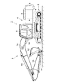
図1および図2は、本発明の実施の形態による油圧ショベル1を示している。油圧ショベル1は、自走可能なクローラ式の下部走行体2と、下部走行体2上に旋回装置3を介して旋回可能に搭載された上部旋回体4と、上部旋回体4の前側に設けられ掘削作業等を行う作業装置7とを備えている。このとき、下部走行体2と上部旋回体4とは、油圧ショベル1の車体を構成している。   1 and 2 show a hydraulic excavator 1 according to an embodiment of the present invention. The excavator 1 is provided on the front side of the upper swing body 4, a crawler type lower travel body 2 that can be self-running, an upper swing body 4 that is mounted on the lower travel body 2 via a swivel device 3. And a working device 7 for performing excavation work and the like. At this time, the lower traveling body 2 and the upper swing body 4 constitute a vehicle body of the hydraulic excavator 1.

上部旋回体4は、支持構造体を形成する旋回フレーム5と、旋回フレーム5の左前側に搭載された後述のキャブ9と、キャブ9の後側に位置して旋回フレーム5に搭載されエンジン、油圧ポンプ、コントロールバルブ等(いずれも図示せず)を覆う建屋カバー6と、建屋カバー6の後側に位置して旋回フレーム5の後部に取付けられ、作業装置7との重量バランスをとるカウンタウエイト8とを備えている。   The upper swing body 4 includes a swing frame 5 forming a support structure, a cab 9 described later mounted on the left front side of the swing frame 5, and an engine mounted on the swing frame 5 on the rear side of the cab 9, A building cover 6 that covers a hydraulic pump, a control valve, etc. (both not shown), and a counterweight that is positioned on the rear side of the building cover 6 and attached to the rear part of the swivel frame 5 to balance the weight with the working device 7 8 and.

作業装置7は、上部旋回体4に俯仰動可能に設けられている。具体的には、作業装置7は、上部旋回体4の前側で左右方向の中央付近に配置され、旋回フレーム5に取り付けられている。図1に示すように、作業装置7は、例えばブーム7A、アーム7B、バケット7Cと、これらを駆動するブームシリンダ7D、アームシリンダ7E、バケットシリンダ7Fとによって構成されている。作業装置7は多関節構造となり、ブーム7A、アーム7B、バケット7Cが、互いにピン結合されている。作業装置7は、シリンダ7D〜7Fを伸長または縮小することによって俯仰動し、例えば土砂、岩石等の掘削作業や積込み作業を行う。   The work device 7 is provided on the upper swing body 4 so as to be able to move up and down. Specifically, the work device 7 is disposed near the center in the left-right direction on the front side of the upper swing body 4 and is attached to the swing frame 5. As shown in FIG. 1, the work device 7 includes, for example, a boom 7A, an arm 7B, and a bucket 7C, and a boom cylinder 7D, an arm cylinder 7E, and a bucket cylinder 7F that drive these. The work device 7 has a multi-joint structure, and the boom 7A, the arm 7B, and the bucket 7C are pin-coupled to each other. The working device 7 moves up and down by extending or contracting the cylinders 7D to 7F, and performs excavation work or loading work such as earth and sand or rock.

また、ブーム7Aの基端部は、旋回フレーム5にピン結合されている。旋回フレーム5には、作業装置7の傾斜角度として、ブーム7Aの傾斜角度(ブーム角)を検出するブーム角センサ7Gが設けられている。ブーム角センサ7Gは、後述のモニタ画像処理装置28に接続され、ブーム角の検出結果を、モニタ画像処理装置28に向けて出力する。   The base end portion of the boom 7 </ b> A is pin-coupled to the turning frame 5. The revolving frame 5 is provided with a boom angle sensor 7G that detects the tilt angle (boom angle) of the boom 7A as the tilt angle of the work device 7. The boom angle sensor 7G is connected to a monitor image processing device 28, which will be described later, and outputs a boom angle detection result toward the monitor image processing device 28.

キャブ9は、オペレータOPが搭乗する運転室を画成する。キャブ9は、上部旋回体4の前側で左右方向の左側に配置されている。このため、キャブ9の右側には、作業装置7が隣合った状態で配置されている。   The cab 9 defines a cab in which the operator OP is boarded. The cab 9 is disposed on the left side in the left-right direction on the front side of the upper swing body 4. For this reason, on the right side of the cab 9, the working device 7 is arranged adjacent to each other.

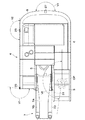
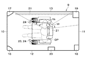
図3および図4に示すように、キャブ9は、前面部10、後面部11、左側面部12、右側面部13、天面部14を備え、これらによって囲まれたボックス状に形成されている。また、キャブ9の下側には、床面と形成するフロア部材15が設けられている。   As shown in FIGS. 3 and 4, the cab 9 includes a front surface portion 10, a rear surface portion 11, a left side surface portion 12, a right side surface portion 13, and a top surface portion 14, and is formed in a box shape surrounded by these. Further, a floor member 15 to be formed with the floor surface is provided below the cab 9.

前面部10は、キャブ9の前後方向の前側に配置されている。前面部10は、前面パネル10Aと、前面パネル10Aに取り付けられた前窓10Bとを備えている。前窓10Bは、例えば透明なガラス板を用いて上,下方向に延びる長方形の板状に形成されている。このため、キャブ9内に搭乗したオペレータOPは、前窓10Bを通じて、前方を目視することができる。   The front surface portion 10 is disposed on the front side of the cab 9 in the front-rear direction. The front unit 10 includes a front panel 10A and a front window 10B attached to the front panel 10A. The front window 10B is formed in a rectangular plate shape that extends upward and downward using, for example, a transparent glass plate. For this reason, the operator OP boarded in the cab 9 can visually observe the front through the front window 10B.

後面部11は、前面部10と前後方向で対面している。後面部11は、後面パネル11Aと、後面パネル11Aに取り付けられた後窓11Bとを備えている。後窓11Bは、例えば透明なガラス板を用いて長方形の板状に形成され、建屋カバー6よりも上側に配置されている。   The rear surface portion 11 faces the front surface portion 10 in the front-rear direction. The rear surface portion 11 includes a rear panel 11A and a rear window 11B attached to the rear panel 11A. The rear window 11 </ b> B is formed in a rectangular plate shape using, for example, a transparent glass plate, and is disposed above the building cover 6.

左側面部12は、キャブ9の左右方向の左側に配置されている。このとき、左側面部12は、右側面部13に比べて左右方向で作業装置7から離れた位置に配置されている。左側面部12は、左側面パネル12Aと、左側面パネル12Aの前側に設けられた乗降口12Bと、乗降口12Bを開,閉するためのドア12Cとを備えている。オペレータOPは、ドア12Cを開くことにより、乗降口12Bを通じてキャブ9内に乗り降りする。   The left side surface portion 12 is disposed on the left side of the cab 9 in the left-right direction. At this time, the left side surface portion 12 is disposed at a position farther from the work device 7 in the left-right direction than the right side surface portion 13. The left side surface portion 12 includes a left side panel 12A, an entrance 12B provided on the front side of the left side panel 12A, and a door 12C for opening and closing the entrance 12B. The operator OP gets in and out of the cab 9 through the entrance 12B by opening the door 12C.

右側面部13は、キャブ9の左右方向の右側に配置されている。このとき、右側面部13は、左側面部12に比べて左右方向で作業装置7に近い位置に配置されている。左側面部12と右側面部13とは、前面部10および後面部11を挟んで左右方向で対面している。右側面部13は、右側面パネル13Aと、右側面パネル13Aの上下方向の中間部から上側に亘る範囲に設けられた右窓13Bとを備えている。右窓13Bは、例えば透明なガラス板を用いて板状に形成されている。   The right side surface portion 13 is disposed on the right side of the cab 9 in the left-right direction. At this time, the right side surface portion 13 is disposed closer to the work device 7 in the left-right direction than the left side surface portion 12. The left side surface portion 12 and the right side surface portion 13 face each other in the left-right direction across the front surface portion 10 and the rear surface portion 11. The right side surface portion 13 includes a right side surface panel 13A and a right window 13B provided in a range extending from an intermediate portion in the vertical direction of the right side surface panel 13A to the upper side. The right window 13B is formed in a plate shape using, for example, a transparent glass plate.

前面部10と左側面部12とが交わる角隅部には左前ピラー16が形成され、前面部10と右側面部13とが交わる角隅部には右前ピラー17が形成されている。また、後面部11と左側面部12とが交わる角隅部には左後ピラー18が形成され、後面部11と右側面部13とが交わる角隅部には右後ピラー19が形成されている。左側面部12の前後方向の中間位置にはセンタピラー20が形成されている。センタピラー20には、ヒンジ20Aを介してドア12Cが開,閉可能に取り付けられている。   A left front pillar 16 is formed at a corner corner where the front surface portion 10 and the left side surface portion 12 intersect, and a right front pillar 17 is formed at a corner corner portion where the front surface portion 10 and the right side surface portion 13 intersect. Further, a left rear pillar 18 is formed at a corner corner where the rear surface portion 11 and the left side surface portion 12 intersect, and a right rear pillar 19 is formed at a corner corner portion where the rear surface portion 11 and the right side surface portion 13 intersect. A center pillar 20 is formed at an intermediate position in the front-rear direction of the left side surface portion 12. A door 12C is attached to the center pillar 20 through a hinge 20A so as to be openable and closable.

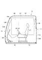
キャブ9内には、オペレータOPが着座する運転席21が設けられる。これに加えて、キャブ9には、油圧ショベル1の走行動作、作業動作および旋回動作をオペレータOPが操作するための操作装置22〜24が設けられている。具体的には、キャブ9内には、運転席21の周囲に位置して、操作レバー、操作ペダル等からなる走行操作装置22と、操作レバー等からなる旋回操作装置23と、操作レバー等からなる作業操作装置24とが設けられている。   A driver's seat 21 on which an operator OP is seated is provided in the cab 9. In addition, the cab 9 is provided with operating devices 22 to 24 for the operator OP to operate the traveling operation, the working operation, and the turning operation of the excavator 1. Specifically, the cab 9 includes a travel operation device 22 including an operation lever and an operation pedal, a turning operation device 23 including an operation lever, and an operation lever, which are positioned around the driver's seat 21. The work operation device 24 is provided.

走行操作装置22は、例えば運転席21の前側に配置されている。また、旋回操作装置23は、例えば運転席21の左側に配置された操作レバーのうち前後方向の操作部分が該当する。さらに、作業操作装置24は、運転席21の左側に配置された操作レバーのうち左右方向の操作部分(アーム操作)と、運転席21の右側に配置された操作レバーのうち前後方向の操作部分(ブーム操作)と左右方向の操作部分(バケット操作)とが該当する。なお、操作レバーの操作方向と旋回動作や作業動作との関係は、前述したものに限らず、油圧ショベル1の仕様等に応じて適宜設定される。   The traveling operation device 22 is disposed, for example, on the front side of the driver seat 21. Further, the turning operation device 23 corresponds to an operation portion in the front-rear direction among the operation levers arranged on the left side of the driver seat 21, for example. Furthermore, the work operation device 24 includes a left-right operation portion (arm operation) among the operation levers arranged on the left side of the driver seat 21 and a front-rear operation portion of the operation levers arranged on the right side of the driver seat 21. (Boom operation) and the operation part in the left-right direction (bucket operation) correspond. The relationship between the operation direction of the operation lever, the turning operation, and the work operation is not limited to that described above, and is appropriately set according to the specifications of the hydraulic excavator 1 and the like.

ここで、操作装置22〜24には、これらの操作量(レバー操作量OA)を検出する操作量センサ22A〜24Aがそれぞれ設けられている。これらの操作量センサ22A〜24Aは、例えば下部走行体2の走行操作、上部旋回体4の旋回操作、作業装置7の俯仰動操作(掘削操作)等のような車体の操作状態を検出する車体操作状態検出装置を構成している。   Here, the operation devices 22 to 24 are provided with operation amount sensors 22A to 24A for detecting these operation amounts (lever operation amounts OA), respectively. These operation amount sensors 22A to 24A detect the operation state of the vehicle body such as the traveling operation of the lower traveling body 2, the turning operation of the upper revolving body 4, the uplifting operation (excavation operation) of the work device 7, and the like. An operation state detection device is configured.

具体的には、操作量センサ22A〜24Aは、コントロールバルブ(図示せず)のパイロット圧を検出するパイロット圧センサによって構成されている。この場合、コントロールバルブは、走行操作装置22によるパイロット圧に応じて、走行用の油圧モータに対する圧油の供給と排出を切り換える。コントロールバルブは、旋回操作装置23によるパイロット圧に応じて、旋回装置3の油圧モータに対する圧油の供給と排出を切り換える。コントロールバルブは、作業操作装置24によるパイロット圧に応じて、シリンダ7D〜7Fに対する圧油の供給と排出を切り換える。このため、操作量センサ22A〜24Aは、操作装置22〜24によるパイロット圧を検出することによって、走行動作、旋回動作、作業動作を検出する。なお、操作量センサ22A〜24Aは、パイロット圧センサに限らず、例えば操作装置22〜24の操作位置を検出する位置センサ等でもよい。   Specifically, the operation amount sensors 22A to 24A are constituted by pilot pressure sensors that detect the pilot pressure of a control valve (not shown). In this case, the control valve switches between supply and discharge of pressure oil to the traveling hydraulic motor in accordance with the pilot pressure from the traveling operation device 22. The control valve switches between supply and discharge of pressure oil to the hydraulic motor of the swing device 3 in accordance with the pilot pressure by the swing operation device 23. The control valve switches between supply and discharge of pressure oil to the cylinders 7 </ b> D to 7 </ b> F according to the pilot pressure by the work operation device 24. For this reason, the operation amount sensors 22A to 24A detect the traveling operation, the turning operation, and the work operation by detecting the pilot pressure by the operation devices 22 to 24. The operation amount sensors 22A to 24A are not limited to pilot pressure sensors, and may be position sensors that detect the operation positions of the operation devices 22 to 24, for example.

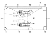
図2および図5に示すように、カメラ25〜27は、上部旋回体4に設けられ、前側風景、後側風景および左右方向で作業装置7を挟んでキャブ9とは反対側の風景を撮影する。即ち、カメラ25〜27は、上部旋回体4の前方から後方に亘る範囲で右側の車外風景を撮影する。   As shown in FIGS. 2 and 5, the cameras 25 to 27 are provided on the upper swing body 4 and photograph the front landscape, the rear landscape, and the landscape on the opposite side of the cab 9 with the work device 7 sandwiched between the left and right directions. To do. In other words, the cameras 25 to 27 capture the right outside scenery in the range from the front to the rear of the upper swing body 4.

具体的には、前側カメラ25は、上部旋回体4の前部右側に設けられ、キャブ9内に着座したオペレータOPから見て、主として右前方の風景を撮影する。これにより、前側カメラ25は、前側視界V1に応じた前側カメラ画像を出力する。   Specifically, the front camera 25 is provided on the right side of the front part of the upper swing body 4, and mainly captures the right front scenery as viewed from the operator OP seated in the cab 9. As a result, the front camera 25 outputs a front camera image corresponding to the front field of view V1.

右側カメラ26は、上部旋回体4の右側に設けられ、キャブ9内に着座したオペレータOPから見て、主として右側の風景を撮影する。即ち、右側カメラ26は、上部旋回体4のうち左右方向でキャブ9が設けられた左側とは反対側(右側)の風景を撮影する。これにより、右側カメラ26は、右側視界V2に応じた右側カメラ画像を出力する。   The right camera 26 is provided on the right side of the upper swing body 4 and mainly photographs the landscape on the right side when viewed from the operator OP seated in the cab 9. That is, the right camera 26 photographs the landscape on the opposite side (right side) of the upper swing body 4 from the left side where the cab 9 is provided in the left-right direction. As a result, the right camera 26 outputs a right camera image corresponding to the right field of view V2.

後側カメラ27は、上部旋回体4の後方に設けられ、キャブ9内に着座したオペレータOPから見て、主として後方の風景を撮影する。これにより、後側カメラ27は、後側視界V3に応じた後側カメラ画像を出力する。   The rear camera 27 is provided behind the upper swing body 4 and mainly shoots a landscape behind the operator OP seated in the cab 9. As a result, the rear camera 27 outputs a rear camera image corresponding to the rear view field V3.

カメラ25〜27は、運転席21に着座したオペレータOPから死角になる車外風景を撮影する。カメラ25〜27は、例えばビデオカメラ等によって構成され、動画または連続的な静止画が撮影可能である。カメラ25〜27は、モニタ画像処理装置28に接続され、それぞれが撮影した風景の画像信号を、モニタ画像処理装置28に向けて出力する。   The cameras 25 to 27 capture a scene outside the vehicle that is a blind spot from the operator OP seated in the driver's seat 21. The cameras 25 to 27 are configured by, for example, a video camera or the like, and can capture a moving image or continuous still images. The cameras 25 to 27 are connected to the monitor image processing device 28, and each outputs an image signal of a landscape taken by the camera 25 to the monitor image processing device 28.

モニタ画像処理装置28は、カメラ25〜27と後述のモニタ装置31とに接続されている。モニタ画像処理装置28は、例えばマイクロコンピュータによって構成され、カメラ25〜27によって撮影した車外風景に基づいて、オペレータOPの死角部分を含む風景画像を生成し、モニタ装置31に出力する。具体的には、モニタ画像処理装置28は、3台のカメラ25〜27によって撮影された3方向の画像を合成して、例えばオペレータOPから見て上部旋回体4の右側で視野角が180°近くまで広がった合成画像CIを生成する(図6参照)。図6は、上部旋回体4の右側に土砂ESを運搬するダンプトラックDTが配置されたときの合成画像CIの一例を示している。このとき、合成画像CIの視界V0は、前側視界V1、右側視界V2および後側視界V3を合わせたものになっている。なお、複数の画像の合成には、例えば特開2015−15527号公報等に開示された各種のビデオモザイキング技術を用いることができる。   The monitor image processing device 28 is connected to cameras 25 to 27 and a monitor device 31 described later. The monitor image processing device 28 is constituted by, for example, a microcomputer, generates a landscape image including a blind spot portion of the operator OP based on the outside scenery photographed by the cameras 25 to 27, and outputs the landscape image to the monitor device 31. Specifically, the monitor image processing device 28 synthesizes the images in the three directions taken by the three cameras 25 to 27 and has a viewing angle of 180 ° on the right side of the upper swing body 4 when viewed from the operator OP, for example. A composite image CI spreading to the vicinity is generated (see FIG. 6). FIG. 6 shows an example of the composite image CI when the dump truck DT carrying the earth and sand ES is arranged on the right side of the upper swing body 4. At this time, the visual field V0 of the composite image CI is a combination of the front visual field V1, the right visual field V2, and the rear visual field V3. Note that various video mosaicing techniques disclosed in, for example, Japanese Patent Application Laid-Open No. 2015-15527 can be used to synthesize a plurality of images.

また、モニタ画像処理装置28は、操作量センサ22A〜24A、ブーム角センサ7G、手元側画像操作装置29、情報処理装置30にも接続されている。モニタ画像処理装置28は、画像切換え装置を備え、後述の画像切換え処理のプログラムを実行する。具体的には、モニタ画像処理装置28は、操作量センサ22A〜24Aからの信号に基づいて、油圧ショベル1の作業状態を判別し、作業状態に応じて合成画像CIの一部を抽出する。これにより、モニタ画像処理装置28は、走行動作を行うときに表示する走行用画面35と、作業動作を行うときに表示する作業用画面36と、旋回動作を行うときに表示する旋回用画面37とを生成する。   The monitor image processing device 28 is also connected to the operation amount sensors 22A to 24A, the boom angle sensor 7G, the hand side image operation device 29, and the information processing device 30. The monitor image processing device 28 includes an image switching device and executes an image switching processing program to be described later. Specifically, the monitor image processing device 28 determines the working state of the excavator 1 based on the signals from the operation amount sensors 22A to 24A, and extracts a part of the composite image CI according to the working state. Thereby, the monitor image processing device 28 displays the traveling screen 35 displayed when performing the traveling operation, the working screen 36 displayed when performing the working operation, and the turning screen 37 displayed when performing the turning operation. And generate

これに加えて、モニタ画像処理装置28は、例えば油圧ショベル1の停止状態等のように、作業動作、旋回動作、走行動作のいずれにも該当しないときに表示する標準画面34を生成する。この標準画面34は、合成画像CI全部でもよく、合成画像CIの一部を抽出したものでもよく、合成画像CIの範囲内でオペレータOPによって任意に設定可能である。そして、モニタ画像処理装置28は、油圧ショベル1の作業状態に応じて、これらの画面34〜37のうちいずれか1つを選択的にモニタ装置31に表示し、モニタ装置31に表示する画面を切り換える。   In addition to this, the monitor image processing device 28 generates a standard screen 34 to be displayed when none of the work operation, the turning operation, and the traveling operation, such as a stop state of the excavator 1, for example. The standard screen 34 may be the entire composite image CI or a part of the composite image CI extracted, and can be arbitrarily set by the operator OP within the range of the composite image CI. The monitor image processing device 28 selectively displays any one of these screens 34 to 37 on the monitor device 31 according to the working state of the excavator 1, and displays a screen to be displayed on the monitor device 31. Switch.

モニタ画像処理装置28は、車外風景に対して死角を作り出す部材を、オペレータOPの操作または作業状態に基づいて、モニタ装置31の画面に表示させることができる。具体的には、モニタ画像処理装置28は、右前ピラー17、右後ピラー19、ブーム7Aの位置と大きさを把握し、これらの像を表示画面中に合成する。このとき、右前ピラー17の像IMfと右後ピラー19の像IMrは、例えばその外形に沿った破線を用いて表示される。また、ブーム7Aの像IMbは、例えばその外形に沿った破線を用いて表示され、または、半透明な影を用いて表示される。これらの像IMf,IMr,IMbを表示するか否かは、オペレータOPが手元側画像操作装置29やモニタ装置31表面のタッチパネル32を操作することによって、設定することができる。ブーム7Aの像IMbは、ブーム角センサ7Gによるブーム角の検出結果に基づいて、実際のブーム7Aの俯仰動に応じて回動変位する。   The monitor image processing device 28 can display a member that creates a blind spot with respect to the scenery outside the vehicle on the screen of the monitor device 31 based on the operation or work state of the operator OP. Specifically, the monitor image processing device 28 grasps the positions and sizes of the right front pillar 17, the right rear pillar 19, and the boom 7A, and synthesizes these images on the display screen. At this time, the image IMf of the right front pillar 17 and the image IMr of the right rear pillar 19 are displayed using, for example, broken lines along the outer shape thereof. Further, the image IMb of the boom 7A is displayed using, for example, a broken line along its outer shape, or is displayed using a translucent shadow. Whether or not to display these images IMf, IMr, and IMb can be set by the operator OP operating the touch panel 32 on the surface of the hand side image operation device 29 or the monitor device 31. The image IMb of the boom 7A is rotationally displaced according to the actual lifting and lowering motion of the boom 7A based on the detection result of the boom angle by the boom angle sensor 7G.

また、モニタ画像処理装置28には、油圧ショベル1を駆動するに際して補助的な各種の情報が情報処理装置30から入力される。情報処理装置30からの入力には、例えば操作装置23,24のガイダンス情報と、作業現場の地図情報と、作業当日を含めた作業全般の日程を示す作業工程表と、監督者からの作業指示内容とが含まれる。このため、モニタ画像処理装置28は、情報処理装置30からの各種の情報に基づいて、補助画面34A〜37Aを生成し、これらの補助画面34A〜37Aをモニタ装置31の画面上に表示させることができる。   Further, the monitor image processing device 28 receives various auxiliary information from the information processing device 30 when driving the excavator 1. The input from the information processing device 30 includes, for example, guidance information of the operation devices 23 and 24, map information on the work site, a work process table showing a schedule of all work including the work day, and work instructions from the supervisor Content. Therefore, the monitor image processing device 28 generates auxiliary screens 34 </ b> A to 37 </ b> A based on various information from the information processing device 30 and displays these auxiliary screens 34 </ b> A to 37 </ b> A on the screen of the monitor device 31. Can do.

手元側画像操作装置29は、モニタ装置31に表示される標準画面34の画像を操作する。図3に示すように、手元側画像操作装置29は、運転席21よりもモニタ装置31に近い位置に配置されている。具体的には、手元側画像操作装置29は、例えば運転席21の右側に位置するコンソールボックス等に取り付けられている。手元側画像操作装置29は、表示領域選択ボタン29A、死角対象物表示選択ボタン29B、補助情報表示選択ボタン29Cおよび固定ON/OFFボタン29Dを備える。   The hand side image operation device 29 operates the image of the standard screen 34 displayed on the monitor device 31. As shown in FIG. 3, the hand side image operation device 29 is arranged at a position closer to the monitor device 31 than the driver seat 21. Specifically, the hand side image operation device 29 is attached to, for example, a console box located on the right side of the driver's seat 21. The hand side image operation device 29 includes a display area selection button 29A, a blind spot object display selection button 29B, an auxiliary information display selection button 29C, and a fixed ON / OFF button 29D.

表示領域選択ボタン29Aは、合成画像CIの範囲で、モニタ装置31の標準画面34に表示する画像の大きさや領域を選択する。オペレータOPは、表示領域選択ボタン29Aを操作することによって、例えば肉眼視同等の範囲、肉眼視同等の範囲に右前ピラー17による死角を含む前方部分を追加した範囲、肉眼視同等の範囲に右後ピラー19による死角を含む後方部分を追加した範囲、肉眼視同等の範囲に2本のピラー17,19による死角を含む範囲、合成画像CIの範囲内で任意に設定した範囲等を選択することができる。これにより、表示領域選択ボタン29Aは、オペレータOPの意思に応じた視野範囲の画像をモニタ装置31に表示させることができる。   The display area selection button 29A selects the size and area of the image to be displayed on the standard screen 34 of the monitor device 31 within the range of the composite image CI. The operator OP operates the display area selection button 29A to, for example, a range equivalent to the naked eye, a range where the front part including the blind spot by the right front pillar 17 is added to the visual equivalent range, and a right rear side to the visual equivalent range. It is possible to select a range in which a rear portion including a blind spot due to the pillar 19 is added, a range including a blind spot due to the two pillars 17 and 19 in a range equivalent to the naked eye, a range arbitrarily set within the range of the composite image CI, and the like. it can. Thereby, the display area selection button 29A can display an image in the visual field range according to the intention of the operator OP on the monitor device 31.

死角対象物表示選択ボタン29Bは、モニタ装置31の標準画面34に死角対象物を表示するか否かを選択する。具体的には、死角対象物表示選択ボタン29Bは、オペレータOPの操作によって、右前ピラー17、右後ピラー19、ブーム7Aのうち表示するものを選択する。これにより、死角対象物表示選択ボタン29Bによって選択されなかったものは、標準画面34から消去される。このため、死角を作り出す右前ピラー17、右後ピラー19、ブーム7Aのうち全てを表示することもでき、全てを消去することもできる。これらの表示と非表示は、オペレータOPが意思に応じて、任意に選択することができる。なお、死角対象物には、右前ピラー17、右後ピラー19、ブーム7Aに加えて、上部旋回体4の右側車体部分を加えてもよい。   The blind spot object display selection button 29B selects whether or not to display the blind spot object on the standard screen 34 of the monitor device 31. Specifically, the blind spot object display selection button 29B selects the one to be displayed among the right front pillar 17, the right rear pillar 19, and the boom 7A by the operation of the operator OP. As a result, those not selected by the blind spot object display selection button 29B are deleted from the standard screen 34. For this reason, it is also possible to display all of the right front pillar 17, the right rear pillar 19, and the boom 7A that create the blind spot, or to delete all of them. These displays and non-displays can be arbitrarily selected by the operator OP as desired. In addition to the right front pillar 17, the right rear pillar 19, and the boom 7 </ b> A, the right-side vehicle body portion of the upper swing body 4 may be added to the blind spot object.

補助情報表示選択ボタン29Cは、モニタ装置31の標準画面34に補助画面34Aを表示するか否かを選択する。具体的には、補助情報表示選択ボタン29Cは、オペレータOPの操作によって、補助画面34Aの表示が選択されると、モニタ装置31の標準画面34には補助画面34Aが表示される。一方、補助情報表示選択ボタン29Cは、オペレータOPの操作によって、補助画面34Aの非表示が選択されると、モニタ装置31の標準画面34から補助画面34Aは消去されると共に、再表示ボタン38が表示される。この状態で、オペレータOPが再表示ボタン38を操作すると、補助画面34Aは非表示状態から表示状態に切り換わる。   The auxiliary information display selection button 29 </ b> C selects whether or not to display the auxiliary screen 34 </ b> A on the standard screen 34 of the monitor device 31. Specifically, the auxiliary information display selection button 29C displays the auxiliary screen 34A on the standard screen 34 of the monitor device 31 when the display of the auxiliary screen 34A is selected by the operation of the operator OP. On the other hand, in the auxiliary information display selection button 29C, when the non-display of the auxiliary screen 34A is selected by the operation of the operator OP, the auxiliary screen 34A is deleted from the standard screen 34 of the monitor device 31 and the redisplay button 38 is displayed. Is displayed. When the operator OP operates the re-display button 38 in this state, the auxiliary screen 34A is switched from the non-display state to the display state.

なお、補助画面34Aの非表示状態で、補助情報表示選択ボタン29Cによって補助画面34Aの表示を選択したときに、補助画面34Aを再表示してもよい。また、手元側画像操作装置29は、補助情報表示選択ボタン29Cとは別個に再表示ボタンを備えてもよい。   Note that, when the display of the auxiliary screen 34A is selected by the auxiliary information display selection button 29C while the auxiliary screen 34A is not displayed, the auxiliary screen 34A may be displayed again. Further, the hand side image operation device 29 may include a redisplay button separately from the auxiliary information display selection button 29C.

固定ON/OFFボタン29Dは、モニタ装置31の標準画面34を固定するか、作業状態に応じて切り換えるかを選択する。具体的には、固定ON/OFFボタン29Dは、オペレータOPの操作によって、「固定ON」に設定されると、モニタ装置31を標準画面34に固定する。これにより、油圧ショベル1の作業状態が走行動作、旋回動作、作業動作のいずれかに切り換わっても、モニタ装置31には標準画面34が表示された状態になり、走行用画面35、作業用画面36、旋回用画面37に切り換わることはない。   The fixed ON / OFF button 29D selects whether to fix the standard screen 34 of the monitor device 31 or to switch according to the work state. Specifically, the fixed ON / OFF button 29D fixes the monitor device 31 to the standard screen 34 when set to “fixed ON” by the operation of the operator OP. Thereby, even if the working state of the hydraulic excavator 1 is switched to any of the traveling operation, the turning operation, and the working operation, the standard screen 34 is displayed on the monitor device 31, and the traveling screen 35, the working screen The screen 36 and the turning screen 37 are not switched.

一方、固定ON/OFFボタン29Dは、オペレータOPの操作によって、「固定OFF」に設定されると、作業状態に応じてモニタ装置31が標準画面34から切り換わるのを許可する。これにより、油圧ショベル1の作業状態が走行動作、旋回動作、作業動作のいずれかに切り換わると、モニタ装置31は、作業状態に応じて標準画面34から走行用画面35、作業用画面36、旋回用画面37のいずれかに切り換わる。   On the other hand, when the fixed ON / OFF button 29D is set to “fixed OFF” by the operation of the operator OP, the monitor device 31 is allowed to switch from the standard screen 34 according to the work state. As a result, when the work state of the excavator 1 is switched to any one of the travel operation, the turning operation, and the work operation, the monitor device 31 changes from the standard screen 34 to the travel screen 35, the work screen 36, according to the work state. The screen is switched to one of the screens 37 for turning.

モニタ装置31は、モニタ画像処理装置28に接続され、カメラ25〜27が撮影した死角風景を表示する。モニタ装置31は、キャブ9の右窓13Bに重ね合わせた状態で右側面部13に取り付けられている。モニタ装置31は、例えば液晶パネルのように薄型の表示装置によって構成されている。図9ないし図16に示すように、モニタ装置31は、スタート画面33、標準画面34、走行用画面35、作業用画面36、旋回用画面37を有する。モニタ装置31は、モニタ画像処理装置28によって表示画面が制御され、スタート画面33、標準画面34、走行用画面35、作業用画面36、旋回用画面37のいずれかが表示される。   The monitor device 31 is connected to the monitor image processing device 28, and displays a blind spot landscape photographed by the cameras 25 to 27. The monitor device 31 is attached to the right side surface portion 13 in a state of being superimposed on the right window 13B of the cab 9. The monitor device 31 is configured by a thin display device such as a liquid crystal panel. As shown in FIGS. 9 to 16, the monitor device 31 includes a start screen 33, a standard screen 34, a traveling screen 35, a work screen 36, and a turning screen 37. The display screen of the monitor device 31 is controlled by the monitor image processing device 28, and any one of the start screen 33, the standard screen 34, the traveling screen 35, the work screen 36, and the turning screen 37 is displayed.

図9に示すように、スタート画面33は、各種の初期設定を行うための画面である。このため、スタート画面33は、例えば車両の起動時にモニタ装置31に表示される。モニタ装置31は、タッチパネル32を備え、表示領域選択ボタン32A、死角対象物表示選択ボタン32B、補助情報表示選択ボタン32C、固定ON/OFFボタン32Dを有する。表示領域選択ボタン32A、死角対象物表示選択ボタン32B、補助情報表示選択ボタン32C、固定ON/OFFボタン32Dは、表示領域選択ボタン29A、死角対象物表示選択ボタン29B、補助情報表示選択ボタン29C、固定ON/OFFボタン29Dと同じ機能をそれぞれ有する。これらのボタン32A〜32Dは、スタート画面33に表示される。なお、スタート画面33は、車両の起動時に常に表示される必要はない。例えばオペレータOPが設定開始スイッチ(図示せず)等を操作して、各種の設定を希望するときだけ、スタート画面33がモニタ装置31に表示されてもよい。   As shown in FIG. 9, the start screen 33 is a screen for performing various initial settings. For this reason, the start screen 33 is displayed on the monitor device 31 when the vehicle is started, for example. The monitor device 31 includes a touch panel 32, and includes a display area selection button 32A, a blind spot object display selection button 32B, an auxiliary information display selection button 32C, and a fixed ON / OFF button 32D. Display area selection button 32A, blind spot object display selection button 32B, auxiliary information display selection button 32C, fixed ON / OFF button 32D are display area selection button 29A, blind spot object display selection button 29B, auxiliary information display selection button 29C, Each has the same function as the fixed ON / OFF button 29D. These buttons 32 </ b> A to 32 </ b> D are displayed on the start screen 33. Note that the start screen 33 need not always be displayed when the vehicle is started. For example, the start screen 33 may be displayed on the monitor device 31 only when the operator OP operates a setting start switch (not shown) and desires various settings.

図10に示すように、標準画面34は、例えば車両の停止時のように、走行動作、旋回動作、作業動作のいずれにも該当しないときに、モニタ装置31に表示される画面である。標準画面34は、初期状態では肉眼視同等の画像となっている。但し、標準画面34は、肉眼視同等の画像に限らず、表示領域選択ボタン29A,32Aを操作することによって、合成画像CI内でオペレータOPが希望する任意の範囲の画像とすることができる。また、標準画面34では、死角対象物表示選択ボタン29B,32Bによって、死角対象物である右前ピラー17、右後ピラー19、ブーム7Aの全部または一部を表示することができ、これら全部を非表示にすることもできる。   As shown in FIG. 10, the standard screen 34 is a screen displayed on the monitor device 31 when it does not correspond to any of the traveling operation, the turning operation, and the work operation, for example, when the vehicle is stopped. The standard screen 34 is an image equivalent to the naked eye in the initial state. However, the standard screen 34 is not limited to an image equivalent to the naked eye, and can be an image in an arbitrary range desired by the operator OP in the composite image CI by operating the display area selection buttons 29A and 32A. On the standard screen 34, the blind spot object display selection buttons 29B and 32B can display all or a part of the right front pillar 17, the right rear pillar 19, and the boom 7A, which are blind spot objects. It can also be displayed.

図11および図12に示すように、走行用画面35は、車両を走行動作させたときに、モニタ装置31に表示される画面である。走行動作では、車両の進行方向前側の状況を把握する必要がある。このため、走行用画面35は、右窓13Bを肉眼視したときの視野Vsに比べて、視野Vtを進行方向前側に拡大させた画像になっている。   As shown in FIGS. 11 and 12, the traveling screen 35 is a screen displayed on the monitor device 31 when the vehicle is caused to travel. In the traveling operation, it is necessary to grasp the situation on the front side of the traveling direction of the vehicle. Therefore, the traveling screen 35 is an image in which the visual field Vt is enlarged forward in the traveling direction as compared to the visual field Vs when the right window 13B is viewed with the naked eye.

図12は、図6に示す合成画像CIの一例に応じた走行用画面35を示している。この走行用画面35には、上部旋回体4の右側でブーム7Aの死角に位置するダンプトラックDTが表示される。これに加えて、走行用画面35には、右前ピラー17の死角に位置する土砂ESも含めて、上部旋回体4の右前側の風景も併せて表示される。走行用画面35には、死角対象物であるブーム7Aの像IMbおよびピラー17,19の像IMf,IMrが、その外形に沿った破線を用いて表示される。   FIG. 12 shows a travel screen 35 corresponding to an example of the composite image CI shown in FIG. On the traveling screen 35, the dump truck DT located at the blind spot of the boom 7A on the right side of the upper swing body 4 is displayed. In addition, the traveling screen 35 also displays the scenery on the right front side of the upper swing body 4 including the earth and sand ES located in the blind spot of the right front pillar 17. On the traveling screen 35, the image IMb of the boom 7A, which is the blind spot object, and the images IMf and IMr of the pillars 17 and 19 are displayed using broken lines along the outer shape thereof.

図13および図14に示すように、作業用画面36は、車両を作業動作させたときに、モニタ装置31に表示される画面である。具体的には、例えば掘削作業、積込み作業等のように、作業装置7を俯仰動させたときに、作業用画面36は表示される。車両を作業動作させたときには、作業装置7の動作状況を把握する必要がある。このため、作業用画面36は、車外風景中に作業装置7の位置を明示した画像となっている。作業用画面36は、例えば右窓13Bを肉眼視したときの視野Vsと同等の視野Voに応じた画像になっている。   As shown in FIGS. 13 and 14, the work screen 36 is a screen displayed on the monitor device 31 when the vehicle is operated. Specifically, the work screen 36 is displayed when the work device 7 is moved up and down, such as excavation work and loading work. When the vehicle is operated, it is necessary to grasp the operation status of the work device 7. Therefore, the work screen 36 is an image that clearly shows the position of the work device 7 in the scenery outside the vehicle. The work screen 36 is an image corresponding to a visual field Vo equivalent to the visual field Vs when the right window 13B is viewed with the naked eye, for example.

図14は、図6に示す合成画像CIの一例に応じた作業用画面36を示している。この作業用画面36には、上部旋回体4の右側でブーム7Aの死角に位置するダンプトラックDTが表示される。これに加えて、作業用画面36には、死角対象物である作業装置7のブーム7Aの像IMbが半透明な状態で表示される。他の死角対象物であるピラー17,19の像IMf,IMrは、その外形に沿った破線を用いて、作業用画面36に表示される。   FIG. 14 shows a work screen 36 corresponding to an example of the composite image CI shown in FIG. On the work screen 36, the dump truck DT located at the blind spot of the boom 7A on the right side of the upper swing body 4 is displayed. In addition, on the work screen 36, the image IMb of the boom 7A of the working device 7 that is the blind spot object is displayed in a translucent state. The images IMf and IMr of the pillars 17 and 19 that are other blind spot objects are displayed on the work screen 36 using broken lines along the outer shape thereof.

図15および図16に示すように、旋回用画面37は、車両を旋回動作させたときに、モニタ装置31に表示される画面である。具体的には、車両を右旋回させたときに、旋回用画面37は表示される。車両を右旋回させるときには、上部旋回体4の右後方の状況を把握する必要がある。このため、旋回用画面37は、右窓13Bを肉眼視したときの視野Vsに比べて、視野Vrを旋回方向の前方となる右後側に拡大させた画像になっている。   As shown in FIGS. 15 and 16, the turning screen 37 is a screen displayed on the monitor device 31 when the vehicle is turned. Specifically, the turning screen 37 is displayed when the vehicle is turned right. When turning the vehicle to the right, it is necessary to grasp the right rear situation of the upper turning body 4. For this reason, the turning screen 37 is an image in which the visual field Vr is enlarged to the right rear side in front of the turning direction as compared with the visual field Vs when the right window 13B is viewed with the naked eye.

図16は、図6に示す合成画像CIの一例に応じた旋回用画面37を示している。この旋回用画面37には、上部旋回体4の右側でブーム7Aの死角に位置するダンプトラックDTが表示される。これに加えて、旋回用画面37には、右後ピラー19の死角に位置する土砂ESも含めて、上部旋回体4の右後側の風景も併せて表示される。旋回用画面37には、死角対象物であるブーム7Aの像IMbおよびピラー17,19の像IMf,IMrが、その外形に沿った破線を用いて表示される。   FIG. 16 shows a turning screen 37 corresponding to an example of the composite image CI shown in FIG. On the turning screen 37, the dump truck DT located at the blind spot of the boom 7A on the right side of the upper turning body 4 is displayed. In addition to this, on the screen 37 for turning, the scenery on the right rear side of the upper turning body 4 is also displayed together with the earth and sand ES located in the blind spot of the right rear pillar 19. On the turning screen 37, the image IMb of the boom 7A, which is a blind spot object, and the images IMf and IMr of the pillars 17 and 19 are displayed using broken lines along the outer shape.

次に、モニタ画像処理装置28が実行する画像切換え処理のプログラムについて、図7、図9ないし図16を用いて説明する。   Next, an image switching process program executed by the monitor image processing apparatus 28 will be described with reference to FIGS. 7 and 9 to 16.

例えばイグニションキー等によって車両を起動すると、画像処理プログラムが起動する。ステップ1では、モニタ装置31にスタート画面33を表示する(図9参照)。ステップ2では、標準画面設定処理を実行し、オペレータOPの要望に応じて標準画面34を設定する。具体的には、標準画面設定処理では、合成画像CI内で表示する画像の大きさや範囲、死角対象物の表示の有無、標準画面34を固定するか否かを設定する。   For example, when the vehicle is activated by an ignition key or the like, the image processing program is activated. In step 1, a start screen 33 is displayed on the monitor device 31 (see FIG. 9). In step 2, the standard screen setting process is executed, and the standard screen 34 is set according to the request of the operator OP. Specifically, in the standard screen setting process, the size and range of an image to be displayed in the composite image CI, whether or not a blind spot object is displayed, and whether or not to fix the standard screen 34 are set.

続くステップ3では、標準画面34が固定されているか否かを判定する。ステップ3で「YES」と判定したときには、標準画面34が固定された状態となっているので、ステップ4に移行して、固定状態表示部39を用いて、固定ボタンが「ON」状態である旨をモニタ装置31に表示する。続くステップ5では、図10に示す標準画面34をモニタ装置31に表示し、ステップ3以降を繰り返す。   In the subsequent step 3, it is determined whether or not the standard screen 34 is fixed. If “YES” is determined in Step 3, the standard screen 34 is in a fixed state, so the process proceeds to Step 4, and the fixed button is in the “ON” state using the fixed state display unit 39. This is displayed on the monitor device 31. In the subsequent step 5, the standard screen 34 shown in FIG. 10 is displayed on the monitor device 31, and step 3 and subsequent steps are repeated.

一方、ステップ3で「NO」と判定したときには、標準画面34は固定されておらず、標準画面34からの切り換えが許可された状態になっている。このため、ステップ6に移行して、固定状態表示部39を用いて、固定ボタンが「OFF」状態である旨をモニタ装置31に表示する(図10参照)。   On the other hand, when it is determined as “NO” in Step 3, the standard screen 34 is not fixed, and switching from the standard screen 34 is permitted. For this reason, the process proceeds to step 6, and the fact that the fixed button is in the “OFF” state is displayed on the monitor device 31 using the fixed state display unit 39 (see FIG. 10).

続くステップ7では、車両が走行状態か否かを判定する。具体的には、操作量センサ22Aの検出信号に基づいて、走行操作装置22によるパイロット圧が一定時間以上に亘って所定のしきい値を超えたか否かによって、走行動作しているか否かを判定する。なお、走行動作を判定するための一定時間およびパイロット圧のしきい値は、誤検出を抑制できる範囲で適宜設定される。   In the following step 7, it is determined whether or not the vehicle is running. Specifically, based on the detection signal of the operation amount sensor 22A, whether or not the traveling operation is being performed is determined by whether or not the pilot pressure by the traveling operation device 22 has exceeded a predetermined threshold for a certain time or more. judge. Note that the predetermined time for determining the running operation and the threshold value of the pilot pressure are appropriately set within a range in which erroneous detection can be suppressed.

ステップ7で「YES」と判定したときには、車両は走行状態になっている。このため、ステップ8に移行して、走行用画面35をモニタ装置31に表示する(図11および図12参照)。これにより、モニタ装置31には、肉眼視同等となる上部旋回体4の右側の車外風景に、進行方向前方の車外風景を加えた画像が表示される。ステップ8が終了すると、ステップ3以降を繰り返す。   When it is determined “YES” in step 7, the vehicle is in a running state. For this reason, it transfers to step 8 and the screen 35 for driving | running | working is displayed on the monitor apparatus 31 (refer FIG. 11 and FIG. 12). Thereby, the monitor device 31 displays an image obtained by adding the vehicle exterior scenery ahead of the traveling direction to the vehicle exterior scenery on the right side of the upper-part turning body 4 that is equivalent to the naked eye. When step 8 ends, step 3 and subsequent steps are repeated.

ステップ7で「NO」と判定したときには、車両は走行しておらず、下部走行体2は停止している。このため、ステップ9に移行して、車両が作業状態か否かを判定する。具体的には、操作量センサ24Aの検出信号に基づいて、作業操作装置24によるパイロット圧が一定時間以上に亘って所定のしきい値を超えたか否かによって、作業動作しているか否か、即ち作業装置7が俯仰動しているか否かを判定する。なお、作業動作を判定するための一定時間およびパイロット圧のしきい値は、誤検出を抑制できる範囲で適宜設定される。   When it is determined as “NO” in Step 7, the vehicle is not traveling and the lower traveling body 2 is stopped. For this reason, it transfers to step 9 and it is determined whether a vehicle is a working state. Specifically, based on the detection signal of the operation amount sensor 24A, whether or not the work operation is being performed depending on whether or not the pilot pressure by the work operation device 24 has exceeded a predetermined threshold for a certain time or more, That is, it is determined whether or not the working device 7 is moving up and down. Note that the fixed time for determining the work operation and the threshold value of the pilot pressure are appropriately set within a range in which erroneous detection can be suppressed.

ステップ9で「YES」と判定したときには、車両は作業状態になっており、作業装置7が駆動して、掘削作業等が行われている。このため、ステップ10に移行して、作業用画面36をモニタ装置31に表示する(図13および図14参照)。これにより、モニタ装置31には、肉眼視同等となる上部旋回体4の右側の車外風景に加えて、ブーム7Aの像IMbによって作業装置7の位置が明示された状態の画像が表示される。ステップ10が終了すると、ステップ3以降を繰り返す。   When it is determined as “YES” in Step 9, the vehicle is in a working state, and the working device 7 is driven to perform excavation work or the like. Therefore, the process proceeds to step 10 and the work screen 36 is displayed on the monitor device 31 (see FIGS. 13 and 14). As a result, in addition to the scenery outside the vehicle on the right side of the upper-part turning body 4 that is equivalent to the naked eye, the monitor device 31 displays an image in which the position of the work device 7 is clearly indicated by the image IMb of the boom 7A. When step 10 is completed, step 3 and subsequent steps are repeated.

ステップ9で「NO」と判定したときには、作業装置7は停止している。このため、ステップ11に移行して、車両が旋回状態か否かを判定する。具体的には、操作量センサ23Aの検出信号に基づいて、旋回操作装置23によるパイロット圧が一定時間以上に亘って所定のしきい値を超えたか否かによって、上部旋回体4が旋回動作しているか否かを判定する。ここで、上部旋回体4は右旋回と左旋回が可能であるが、ステップ11では、キャブ9が作業装置7側に向けて移動するように、上部旋回体4が右旋回しているか否かを判定する。なお、旋回動作を判定するための一定時間およびパイロット圧のしきい値は、誤検出を抑制できる範囲で適宜設定される。   When it is determined “NO” in step 9, the work device 7 is stopped. Therefore, the process proceeds to step 11 to determine whether or not the vehicle is turning. Specifically, based on the detection signal of the operation amount sensor 23A, the upper swing body 4 swings depending on whether or not the pilot pressure by the swing operation device 23 has exceeded a predetermined threshold value for a certain time or more. It is determined whether or not. Here, the upper turning body 4 can turn right and left, but in step 11, whether or not the upper turning body 4 is turning right so that the cab 9 moves toward the work device 7. Determine whether. Note that the predetermined time for determining the turning motion and the threshold value of the pilot pressure are appropriately set within a range in which erroneous detection can be suppressed.

ステップ11で「YES」と判定したときには、車両は旋回状態になっており、旋回装置3が駆動して、上部旋回体4が右旋回している。このため、ステップ12に移行して、旋回用画面37をモニタ装置31に表示する(図15および図16参照)。これにより、モニタ装置31には、肉眼視同等となる上部旋回体4の右側の車外風景に、旋回方向の前方となる右後側の車外風景を加えた画像が表示される。ステップ12が終了すると、ステップ3以降を繰り返す。   When “YES” is determined in step 11, the vehicle is in a turning state, the turning device 3 is driven, and the upper turning body 4 is turning right. For this reason, it transfers to step 12 and the screen 37 for rotation is displayed on the monitor apparatus 31 (refer FIG. 15 and FIG. 16). As a result, the monitor device 31 displays an image obtained by adding the vehicle exterior scenery on the right rear side that is the front in the turning direction to the vehicle exterior scenery on the right side of the upper turning body 4 that is equivalent to the naked eye. When step 12 is completed, step 3 and subsequent steps are repeated.

ステップ11で「NO」と判定したときには、油圧ショベル1は走行動作、作業動作、旋回動作のいずれも行っていない。このため、ステップ13に移行して、標準画面34をモニタ装置31に表示し、ステップ3以降を繰り返す。   When it is determined as “NO” in step 11, the excavator 1 is not performing any traveling operation, working operation, or turning operation. Therefore, the process proceeds to step 13, the standard screen 34 is displayed on the monitor device 31, and step 3 and subsequent steps are repeated.

なお、上述の画像切換え処理では、走行動作、作業動作、旋回動作の順番で判定するものとしたが、これらの判定順序は適宜入れ換えてもよい。従って、例えば旋回ブーム上げ動作のように、作業動作と旋回動作とを同時に行う複合動作では、作業用画面36と旋回用画面37とのうちいずれの画面を表示してもよい。この点は、走行動作に作業動作や旋回動作が複合されたときでも同様である。また、例えば旋回ブーム上げ動作では、旋回ブーム上げ動作用の画面として、旋回用画面37に作業装置7の位置を明示した画像を表示してもよい。即ち、各種の複合動作では、複合動作専用の画面を表示してもよい。   In the above-described image switching process, the determination is made in the order of the running operation, the work operation, and the turning operation. However, the determination order may be changed as appropriate. Therefore, for example, in the combined operation in which the work operation and the turning operation are performed simultaneously, such as the turning boom raising operation, either the work screen 36 or the turning screen 37 may be displayed. This is the same even when the work operation and the turning operation are combined with the traveling operation. For example, in the turning boom raising operation, an image in which the position of the working device 7 is clearly displayed on the turning screen 37 may be displayed as the turning boom raising operation screen. That is, in various composite operations, a screen dedicated to the composite operation may be displayed.

次に、図7中の標準画面設定処理について、図8および図9を用いて説明する。   Next, the standard screen setting process in FIG. 7 will be described with reference to FIGS.

ステップ21では、表示領域選択処理を行う。このとき、オペレータOPは、表示領域選択ボタン29A,32Aを用いて、合成画像CIの範囲で、モニタ装置31の標準画面34に表示する画像の大きさや領域を選択する。これにより、オペレータOPは、標準画面34に表示する画像として、合成画像CIの全部または一部を選択することができる。   In step 21, display area selection processing is performed. At this time, the operator OP uses the display area selection buttons 29A and 32A to select the size and area of the image to be displayed on the standard screen 34 of the monitor device 31 within the range of the composite image CI. Thereby, the operator OP can select all or part of the composite image CI as an image to be displayed on the standard screen 34.

続くステップ22では、死角対象物表示選択処理を行う。このとき、オペレータOPは、死角対象物表示選択ボタン29B,32Bを用いて、モニタ装置31の標準画面34に死角対象物を表示するか否かを選択する。即ち、ステップ22では、死角対象物となる右前ピラー17、右後ピラー19、ブーム7Aの像IMf,IMr,IMbを表示するか否か選択する。このとき、右前ピラー17、右後ピラー19、ブーム7Aの像IMf,IMr,IMbは、これら全部の表示を選択することもでき、例えばブーム7Aの像IMbだけのように、一部だけの表示を選択することもできる。また、右前ピラー17、右後ピラー19、ブーム7Aの像IMf,IMr,IMbは、これら全部の非表示を選択することもできる。   In the subsequent step 22, blind spot object display selection processing is performed. At this time, the operator OP uses the blind spot object display selection buttons 29B and 32B to select whether or not to display the blind spot object on the standard screen 34 of the monitor device 31. That is, in step 22, it is selected whether or not to display the images IMf, IMr, IMb of the front right pillar 17, the rear right pillar 19, and the boom 7A that are the blind spot objects. At this time, all of the images IMf, IMr, and IMb of the right front pillar 17, the right rear pillar 19, and the boom 7A can be selected. For example, only a part of the image IMb of the boom 7A is displayed. Can also be selected. The right front pillar 17, the right rear pillar 19, and the images IMf, IMr, and IMb of the boom 7 </ b> A can be selected not to display all of them.

続くステップ23では、補助情報表示選択処理を行う。このとき、オペレータOPは、補助情報表示選択ボタン29C,32Cを用いて、モニタ装置31の標準画面34に補助画面34Aを表示するか否かを選択する。これにより、車外風景の全体を確認したときには、補助画面34Aを消去して、車外風景の画像をモニタ装置31全体に表示することができる。一方、各種の情報を閲覧したいときには、補助画面34Aを表示させることができる。   In subsequent step 23, auxiliary information display selection processing is performed. At this time, the operator OP uses the auxiliary information display selection buttons 29C and 32C to select whether or not to display the auxiliary screen 34A on the standard screen 34 of the monitor device 31. Thus, when the entire outside scenery is confirmed, the auxiliary screen 34A can be erased and an image of the outside scenery can be displayed on the entire monitor device 31. On the other hand, when browsing various information, the auxiliary screen 34A can be displayed.

続くステップ24では、画面固定選択処理を行う。このとき、オペレータOPは、固定ON/OFFボタン29D,32Dを用いて、モニタ装置31の標準画面34を固定するか否かを選択する。例えば作業状態に応じた視野の変更を希望しないときには、標準画面34を固定する。これにより、モニタ装置31には、作業状態が変化したときでも、例えば肉眼視同等となった標準画面34を継続して表示させることができる。一方、標準画面34を固定しないときには、作業状態に応じてモニタ装置31に表示する画面を切り換えることができる。   In the following step 24, screen fixing selection processing is performed. At this time, the operator OP uses the fixed ON / OFF buttons 29D and 32D to select whether or not to fix the standard screen 34 of the monitor device 31. For example, when it is not desired to change the field of view according to the work state, the standard screen 34 is fixed. Thereby, even when the working state changes, for example, the standard screen 34 that is equivalent to the naked eye can be continuously displayed on the monitor device 31. On the other hand, when the standard screen 34 is not fixed, the screen displayed on the monitor device 31 can be switched according to the working state.

ステップ24が終了すると、標準画面34の設定が終了したので、リターンする。なお、表示領域選択処理、死角対象物表示選択処理、補助情報表示選択処理、画面固定選択処理には、処理順序の優劣はない。このため、これらの処理順序は適宜入れ換えてもよい。   When step 24 is finished, the setting of the standard screen 34 is finished, and the process returns. The display area selection process, the blind spot object display selection process, the auxiliary information display selection process, and the screen fixing selection process have no superiority or inferiority in the processing order. For this reason, these processing orders may be interchanged as appropriate.

本実施の形態による油圧ショベル1は上述の如き構成を有するもので、次に、この油圧ショベル1の動作について、図9ないし図16を用いて説明する。   The hydraulic excavator 1 according to the present embodiment has the above-described configuration. Next, the operation of the hydraulic excavator 1 will be described with reference to FIGS. 9 to 16.

まず、オペレータOPは、キャブ9に搭乗して運転席21に着座する。この状態で油圧ショベル1を起動すると、モニタ装置31には、図9に示すスタート画面33が表示される。このスタート画面では、オペレータOPは、標準画面34を設定する。具体的には、オペレータOPは、合成画像CI内で表示する画像の大きさや範囲、死角対象物の表示の有無、標準画面34を固定するか否かを設定する。   First, the operator OP gets on the cab 9 and sits on the driver's seat 21. When the excavator 1 is started in this state, a start screen 33 shown in FIG. On this start screen, the operator OP sets the standard screen 34. Specifically, the operator OP sets the size and range of the image to be displayed in the composite image CI, whether or not the blind spot object is displayed, and whether or not to fix the standard screen 34.

標準画面34の設定が終了すると、モニタ装置31は、スタート画面33から標準画面34に切り換わる(図10参照)。標準画面34では、オペレータOPの希望に応じた車外風景が表示される。また、標準画面34を非固定の状態にすると、油圧ショベル1の作業状態に応じて、モニタ装置31に表示される画面が切り換わる。標準画面34が非固定の場合では、油圧ショベル1の作業状態に応じて、標準画面34、走行用画面35、作業用画面36、旋回用画面37のうちいずれか1つの画面がモニタ装置31に表示される。   When the setting of the standard screen 34 is completed, the monitor device 31 switches from the start screen 33 to the standard screen 34 (see FIG. 10). On the standard screen 34, the scenery outside the vehicle according to the request of the operator OP is displayed. Further, when the standard screen 34 is set to the non-fixed state, the screen displayed on the monitor device 31 is switched according to the working state of the excavator 1. When the standard screen 34 is not fixed, one of the standard screen 34, the traveling screen 35, the working screen 36, and the turning screen 37 is displayed on the monitor device 31 according to the working state of the excavator 1. Is displayed.

例えば、オペレータOPが走行操作装置22を操作すると、油圧ショベル1は走行動作し、例えばキャブ9の前方に向けて前進する。このとき、モニタ装置31には、図12に示す走行用画面35が表示される。図11および図12に示すように、走行用画面35は、肉眼視同等となる上部旋回体4の右側の車外風景に、進行方向前方の車外風景を加えた画像となっている。このため、オペレータOPは、モニタ装置31の走行用画面35を目視することによって、作業装置7等の死角の範囲内を含めて進行方向前側の障害物を把握することができる。   For example, when the operator OP operates the travel operation device 22, the excavator 1 travels and moves forward, for example, toward the front of the cab 9. At this time, the traveling screen 35 shown in FIG. As shown in FIGS. 11 and 12, the traveling screen 35 is an image obtained by adding a vehicle exterior scenery ahead of the traveling direction to the vehicle exterior scenery on the right side of the upper-part turning body 4 that is equivalent to the naked eye. For this reason, the operator OP can grasp the obstacle on the front side in the traveling direction including the inside of the blind spot of the work device 7 or the like by viewing the traveling screen 35 of the monitor device 31.

また、走行用画面35には、補助画面35Aとして、例えば作業現場の地図が表示される。これにより、オペレータOPは、例えば地形、障害物の有無等のような作業現場の状況を把握しながら、油圧ショベル1を移動させることができる。なお、走行用画面35の補助画面35Aは、標準画面34の補助画面34Aと同様に、表示の有無、表示位置、表示の大きさ等がスタート画面33で変更可能としてもよい。   Further, on the traveling screen 35, for example, a map of a work site is displayed as the auxiliary screen 35A. Thereby, the operator OP can move the hydraulic excavator 1 while grasping the situation of the work site such as the topography and the presence or absence of obstacles. In addition, as for the auxiliary screen 35A of the traveling screen 35, the presence / absence of display, the display position, the display size, and the like may be changed on the start screen 33 in the same manner as the auxiliary screen 34A of the standard screen 34.

一方、オペレータOPが作業操作装置24を操作すると、油圧ショベル1は作業動作し、作業装置7は俯仰動する。このとき、モニタ装置31には、図14に示す作業用画面36が表示される。図13および図14に示すように、作業用画面36は、肉眼視同等となる上部旋回体4の右側の車外風景に加えて、半透明なブーム7Aの像IMbによって作業装置7の位置が明示された状態の画像となっている。このため、オペレータOPは、モニタ装置31の作業用画面36を目視することによって、作業装置7の動作状況を把握することができる。   On the other hand, when the operator OP operates the work operation device 24, the excavator 1 performs a work operation, and the work device 7 moves up and down. At this time, the work screen 36 shown in FIG. As shown in FIG. 13 and FIG. 14, the work screen 36 shows the position of the work device 7 by the semi-transparent boom 7 </ b> A image IMb in addition to the scenery outside the vehicle on the right side of the upper-part turning body 4 that is equivalent to the naked eye. It is the image of the state that was done. For this reason, the operator OP can grasp the operation status of the work device 7 by viewing the work screen 36 of the monitor device 31.

また、作業用画面36には、補助画面36Aとして、例えば掘削作業を行うときの掘削形状の図面や法面作業を行うときの法面形状の図面等が表示される。これにより、オペレータOPは、作業内容を把握しながら、作業装置7を動作させることができる。なお、作業用画面36の補助画面36Aは、標準画面34の補助画面34Aと同様に、表示の有無、表示位置、表示の大きさ等がスタート画面33で変更可能としてもよい。   In addition, on the work screen 36, for example, a drawing of an excavation shape when performing excavation work, a drawing of a slope shape when performing slope work, and the like are displayed as the auxiliary screen 36A. Thereby, the operator OP can operate the work device 7 while grasping the work content. The auxiliary screen 36 </ b> A of the work screen 36 may be changed on the start screen 33 in the presence / absence of display, display position, display size, and the like, similar to the auxiliary screen 34 </ b> A of the standard screen 34.

さらに、オペレータOPが旋回操作装置23を操作すると、油圧ショベル1は旋回動作し、例えば上部旋回体4は右旋回する。このとき、モニタ装置31には、図16に示す旋回用画面37が表示される。図15および図16に示すように、旋回用画面37は、肉眼視同等となる上部旋回体4の右側の車外風景に、旋回方向の前方となる右後側の車外風景を加えた画像となっている。このため、オペレータOPは、モニタ装置31の旋回用画面37を目視することによって、旋回方向前側の障害物を把握することができる。   Further, when the operator OP operates the turning operation device 23, the excavator 1 turns, for example, the upper turning body 4 turns right. At this time, a turning screen 37 shown in FIG. As shown in FIGS. 15 and 16, the turning screen 37 is an image obtained by adding the vehicle exterior scenery on the right side of the upper turning body 4, which is equivalent to the naked eye, to the vehicle exterior scenery on the right rear side in front of the turning direction. ing. For this reason, the operator OP can grasp the obstacle on the front side in the turning direction by viewing the turning screen 37 of the monitor device 31.

また、旋回用画面37には、補助画面37Aとして、例えば操作レバーの傾転方向と旋回方向の関係とを示す操作装置23,24の操作パターンが表示される。これにより、オペレータOPは、操作パターンが車両毎に異なるときでも、旋回操作の方法を容易に把握することができる。なお、旋回用画面37の補助画面37Aは、標準画面34の補助画面34Aと同様に、表示の有無、表示位置、表示の大きさ等がスタート画面33で変更可能としてもよい。   In addition, on the turning screen 37, as an auxiliary screen 37A, for example, an operation pattern of the operation devices 23 and 24 indicating the relationship between the tilt direction of the operation lever and the turning direction is displayed. Thereby, the operator OP can easily grasp the method of the turning operation even when the operation pattern is different for each vehicle. The auxiliary screen 37 </ b> A of the turning screen 37 may be changed in the start screen 33 in the presence / absence of the display, the display position, the display size, and the like, like the auxiliary screen 34 </ b> A of the standard screen 34.

かくして、本実施の形態では、モニタ画像処理装置28(モニタ制御装置)は、モニタ装置31に表示する画像が変更可能な画像切換え処理を実行する。これにより、オペレータOPの視界と同一サイズの風景に限らず、例えば右前ピラー17を超えて前方に視界が拡大した画像、または、右後ピラー19を超えて後方に視界が拡大した画像をモニタ装置31に表示することができる。これに加えて、ピラー17,19部分の死角をなくした画像をモニタ装置31に表示することができる。このため、オペレータOPの操作または作業状況に応じた画像を、モニタ装置31に表示することができる。   Thus, in the present embodiment, the monitor image processing device 28 (monitor control device) executes an image switching process in which the image displayed on the monitor device 31 can be changed. Thereby, the monitor device is not limited to a landscape having the same size as the field of view of the operator OP, for example, an image in which the field of view is enlarged forward beyond the right front pillar 17 or an image in which the field of view is magnified backward beyond the right rear pillar 19 31 can be displayed. In addition to this, an image in which the blind spots of the pillars 17 and 19 are eliminated can be displayed on the monitor device 31. Therefore, an image corresponding to the operation of the operator OP or the work situation can be displayed on the monitor device 31.

また、画像切換え処理(画像切換え装置)では、操作装置22〜24の操作状態に応じて、モニタ装置31に表示する画像をそれぞれ切り換える。このため、モニタ画像処理装置28は、操作装置22〜24の操作状態に応じて、走行動作と、旋回動作と、作業動作とのうちいずれの作業状態であるかを把握することができる。この結果、画像切換え処理では、操作装置22〜24の操作状態に応じて、自動的にモニタ装置31の画像を切り換えることができ、作業状態に応じた画像をモニタ装置31に表示することができる。   Further, in the image switching process (image switching device), the images to be displayed on the monitor device 31 are switched according to the operation states of the operation devices 22 to 24, respectively. For this reason, the monitor image processing device 28 can grasp which of the traveling operation, the turning operation, and the work operation is in accordance with the operation state of the operation devices 22 to 24. As a result, in the image switching process, the image on the monitor device 31 can be automatically switched according to the operation state of the operation devices 22 to 24, and the image corresponding to the work state can be displayed on the monitor device 31. .

さらに、画像切換え処理では、走行動作と、旋回動作と、作業動作とに応じて、モニタ装置31に表示する画像をそれぞれ切り換える。このため、走行動作するときには、モニタ画像処理装置28は、上部旋回体4の前側風景を含む走行用画面35をモニタ装置31に表示する。これにより、進行方向前側に視野Vtが拡大した走行用画面35をモニタ装置31に表示することができ、オペレータOPは、モニタ装置31を目視することによって、進行方向前側の対象物を視認することができる。   Further, in the image switching process, images to be displayed on the monitor device 31 are switched according to the traveling operation, the turning operation, and the work operation. Therefore, when the traveling operation is performed, the monitor image processing device 28 displays the traveling screen 35 including the front landscape of the upper swing body 4 on the monitor device 31. Thereby, the traveling screen 35 with the visual field Vt enlarged on the front side in the traveling direction can be displayed on the monitor device 31, and the operator OP can visually recognize the object on the front side in the traveling direction by viewing the monitor device 31. Can do.

一方、旋回動作(右旋回動作)するときには、モニタ画像処理装置28は、上部旋回体4の後側風景を含む旋回用画面37をモニタ装置31に表示する。このため、旋回方向前側に視野Vrが拡大した旋回用画面37をモニタ装置31に表示することができ、オペレータOPは、モニタ装置31を目視することによって、旋回方向前側となる右後側の対象物を視認することができる。   On the other hand, when performing the turning operation (right turning operation), the monitor image processing device 28 displays the turning screen 37 including the rear scenery of the upper turning body 4 on the monitor device 31. For this reason, the turning screen 37 with the visual field Vr enlarged on the front side in the turning direction can be displayed on the monitor device 31, and the operator OP can visually observe the monitor device 31 so that the object on the right rear side that becomes the front side in the turning direction can be displayed. You can see things.

さらに、作業動作するときには、モニタ画像処理装置28は、作業装置7の像IMbを含む作業用画面36をモニタ装置31に表示する。このため、車外風景中に作業装置7(ブーム7A)の像IMbを加えた作業用画面36をモニタ装置31に表示することができ、オペレータOPは、モニタ装置31を目視することによって、車外の状況に加えて、作業装置7の動作を把握することができる。   Further, when the work operation is performed, the monitor image processing device 28 displays a work screen 36 including the image IMb of the work device 7 on the monitor device 31. For this reason, the work screen 36 in which the image IMb of the work device 7 (boom 7A) is added to the scenery outside the vehicle can be displayed on the monitor device 31, and the operator OP visually observes the monitor device 31 to In addition to the situation, the operation of the work device 7 can be grasped.

モニタ画像処理装置28は、モニタ装置31に車外風景とは異なる補助画面34A〜37Aを表示する。このため、補助画面34A〜37Aには、例えば作業現場の地図、法面画像等のように作業を補助する画面を表示することができ、補助画面34A〜37Aを省いた場合に比べて、作業効率を高めることができる。これに加えて、モニタ装置31には、作業を補助する補助画面34A〜37Aと併せて、監督者からの指示内容が記載された追加の補助画面を表示することもできる。   The monitor image processing device 28 displays auxiliary screens 34 </ b> A to 37 </ b> A different from the scenery outside the vehicle on the monitor device 31. For this reason, on the auxiliary screens 34A to 37A, for example, a screen for assisting work can be displayed, such as a map of a work site, a slope image, and the like, compared with the case where the auxiliary screens 34A to 37A are omitted. Efficiency can be increased. In addition to this, the monitor device 31 can display an additional auxiliary screen on which the instruction content from the supervisor is described together with auxiliary screens 34A to 37A for assisting the work.

なお、実施の形態では、モニタ画像処理装置28は、3台のカメラ25〜27の撮影画像を用いて、標準画面34、走行用画面35、旋回用画面37、作業用画面36を生成するものとした。本発明はこれに限らず、モニタ画像処理装置28は、例えば1台または2台のカメラの撮影画像を用いて、各種の画面を生成してもよく、4台以上のカメラの撮影画像を用いて、各種の画面を生成してもよい。   In the embodiment, the monitor image processing device 28 generates the standard screen 34, the traveling screen 35, the turning screen 37, and the working screen 36 using the images captured by the three cameras 25 to 27. It was. The present invention is not limited to this, and the monitor image processing device 28 may generate various screens using images captured by one or two cameras, for example, and use images captured by four or more cameras. Various screens may be generated.

実施の形態では、画像切換え処理では、走行動作、作業動作および旋回動作の3つの動作に応じて、モニタ装置31に表示する画面を切り換えるものとした。本発明はこれに限らず、例えば走行動作、作業動作、旋回動作のうちいずれか1つまたは2つの動作に応じて、モニタ装置31に表示する画面を切り換える構成としてもよい。   In the embodiment, in the image switching process, the screen to be displayed on the monitor device 31 is switched according to the three operations of the traveling operation, the work operation, and the turning operation. The present invention is not limited to this, and for example, a screen displayed on the monitor device 31 may be switched according to any one or two of a traveling operation, a work operation, and a turning operation.

また、走行動作、作業動作および旋回動作の3つの動作に限らず、例えば吊荷動作を追加してもよい。この吊荷動作では、作業装置7の動作を把握するために、モニタ装置31には、作業用画面36と同様な吊荷用画面が表示される。これに加えて、吊荷用画面には、補助画面として、例えば操作装置22〜24の操作パターンや作業範囲と吊荷荷重の一覧が表示される。   Moreover, not only three operation | movement of driving | running | working operation | work, work operation | movement, and turning operation | movement, you may add a hanging load operation | movement, for example. In this suspended load operation, in order to grasp the operation of the work device 7, a screen for suspended load similar to the work screen 36 is displayed on the monitor device 31. In addition to this, on the screen for suspended loads, for example, a list of operation patterns, work ranges, and suspended loads of the operation devices 22 to 24 is displayed as an auxiliary screen.

さらに、走行動作は、前進動作と後進動作との2つの動作に分けてもよい。この場合、例えば前進用画面では、視野が前側に拡大した画像を表示し、後進用画面では、視野が後側に拡大した画像を表示してもよい。   Furthermore, the traveling operation may be divided into two operations, a forward operation and a reverse operation. In this case, for example, an image with a visual field enlarged on the front side may be displayed on the forward screen, and an image with the visual field enlarged on the rear side may be displayed on the backward screen.

同様に、旋回動作は、右旋回動作と左旋回動作との2つの動作に分けてもよい。この場合、例えば右旋回用画面では、視野が後側に拡大した画像を表示し、左旋回用画面では、視野が前側に拡大した画像や肉眼視同等の画像を表示してもよい。   Similarly, the turning operation may be divided into two operations, a right turning operation and a left turning operation. In this case, for example, an image with a visual field enlarged to the rear side may be displayed on the right turn screen, and an image with the visual field enlarged to the front side or an image equivalent to the naked eye may be displayed on the left turn screen.

実施の形態では、作業用画面36では、肉眼視と同等の画像を表示するものとした。本発明はこれに限らず、作業用画面36では、例えば右前ピラー17および右後ピラー19の死角部分まで視野を拡大した画像を表示してもよく、標準画面34と同様に合成画像CIから抽出した任意範囲の画像を表示してもよい。同様に、走行用画面35および旋回用画面37でも、オペレータOPの要求に応じて、合成画像CIから抽出した任意範囲の画像を表示してもよい。   In the embodiment, the work screen 36 displays an image equivalent to the naked eye. The present invention is not limited to this, and the work screen 36 may display, for example, an image whose field of view has been expanded to the blind spots of the right front pillar 17 and the right rear pillar 19, and is extracted from the composite image CI in the same manner as the standard screen 34. An arbitrary range of images may be displayed. Similarly, on the traveling screen 35 and the turning screen 37, an image in an arbitrary range extracted from the composite image CI may be displayed in response to a request from the operator OP.

実施の形態では、作業用画面36には、死角対象物である作業装置7のブーム7Aの像IMbが表示されるものとした。本発明はこれに限らず、作業用画面36には、アーム7B、バケット7Cを含めて作業装置7全体の像が表示されてもよい。この場合、モニタ画像処理装置28には、作業装置7の姿勢検出器として、ブーム角センサ7Gに加えて、アーム角センサ、バケット角センサが接続される。モニタ画像処理装置28は、これらのセンサから出力される傾斜角の検出結果に基づいて、ブーム7A、アーム7Bおよびバケット7Cの位置を特定し、作業装置7全体の像を作業用画面36に表示させる。同様に、走行用画面35、旋回用画面37にも、作業装置7全体の像が表示されてもよい。   In the embodiment, the work screen 36 displays the image IMb of the boom 7A of the working device 7 that is the blind spot object. The present invention is not limited to this, and an image of the entire working device 7 including the arm 7B and the bucket 7C may be displayed on the work screen 36. In this case, an arm angle sensor and a bucket angle sensor are connected to the monitor image processing device 28 as a posture detector of the work device 7 in addition to the boom angle sensor 7G. The monitor image processing device 28 identifies the positions of the boom 7A, the arm 7B, and the bucket 7C based on the tilt angle detection results output from these sensors, and displays an image of the entire work device 7 on the work screen 36. Let Similarly, an image of the entire work apparatus 7 may be displayed on the traveling screen 35 and the turning screen 37.

実施の形態では、標準画面34は、標準画面設定処理でオペレータOPが設定した画面とした。本発明はこれに限らず、例えば標準画面34が表示された状態でモニタ装置31の画面をタップすることによって、標準画面設定処理が起動してもよい。また、モニタ装置31の画面(タッチパネル32)をフリックやスワイプすることによって、モニタ装置31に表示される車外風景の方向や範囲を、オペレータOPの操作に応じて変更してもよい。同様に、モニタ装置31の画面等を操作することによって、モニタ装置31に表示される車外風景を拡大または縮小する構成としてもよい。   In the embodiment, the standard screen 34 is a screen set by the operator OP in the standard screen setting process. The present invention is not limited to this. For example, the standard screen setting process may be activated by tapping the screen of the monitor device 31 in a state where the standard screen 34 is displayed. Further, by flicking or swiping the screen (touch panel 32) of the monitor device 31, the direction and range of the scenery outside the vehicle displayed on the monitor device 31 may be changed according to the operation of the operator OP. Similarly, by operating the screen of the monitor device 31 or the like, the outside scenery displayed on the monitor device 31 may be enlarged or reduced.

実施の形態では、作業装置7の左側にキャブ9を設け、キャブ9内の右側面部13にモニタ装置31を設けるものとした。本発明はこれに限らず、キャブ9内の前面部10や後面部11にモニタ装置31を設けてもよいし、例えば作業装置の右側にキャブを設け、キャブ内の左側面部にモニタ装置を設けてもよい。また、キャブ9内にモニタ装置31を複数個設置してもよい。   In the embodiment, the cab 9 is provided on the left side of the working device 7, and the monitor device 31 is provided on the right side surface portion 13 in the cab 9. The present invention is not limited to this, and the monitor device 31 may be provided on the front surface portion 10 or the rear surface portion 11 in the cab 9. For example, the cab is provided on the right side of the working device, and the monitor device is provided on the left side surface portion in the cab. May be. A plurality of monitor devices 31 may be installed in the cab 9.

モニタ装置31は、キャブ9内の右側面パネル13Aに固定的に取り付けられたものに限らず、例えば下側等に移動可能な構成としてもよい。この場合、右窓による肉眼視を希望するときには、モニタ装置31を右側面パネル13Aの下側に移動させることができる。   The monitor device 31 is not limited to the one fixedly attached to the right side panel 13A in the cab 9, and may be configured to be movable downward, for example. In this case, the monitor device 31 can be moved to the lower side of the right side panel 13A when it is desired to visually observe the right window.

モニタ装置31は、液晶パネルに限らず、例えばプロジェクタとスクリーンとによって構成してもよい。この場合、モニタ装置を用いるときには、スクリーンによって右窓を塞ぎ、右窓による肉眼視を希望するときには、スクリーンをキャブの上側や後側に収容してもよい。また、モニタ装置は、電源OFFで透視可能な状態になってもよい。これにより、モニタ装置に電源が供給されない状態でも、キャブの右窓を通じて車外風景を目視確認することができる。   The monitor device 31 is not limited to a liquid crystal panel, and may be constituted by, for example, a projector and a screen. In this case, when the monitor device is used, the right window may be closed with the screen, and when the visual observation with the right window is desired, the screen may be accommodated on the upper side or the rear side of the cab. Further, the monitor device may be in a state that can be seen through when the power is turned off. Thereby, even when the power is not supplied to the monitor device, the scenery outside the vehicle can be visually confirmed through the right window of the cab.

さらに、実施の形態では、建設機械としてクローラ式の油圧ショベル1を例に挙げて説明した。しかし、本発明はこれに限るものではなく、例えばホイール式の下部走行体を備えた油圧ショベルに適用してもよく、台船に旋回体を取付けた浚渫作業用の油圧ショベル、地面に固定されたポストに旋回体が取付けられた定置式の油圧ショベル等に適用してもよい。さらに、例えば油圧クレーン等の他の建設機械にも広く適用できるものである。   Furthermore, in the embodiment, the crawler hydraulic excavator 1 is described as an example of the construction machine. However, the present invention is not limited to this. For example, the present invention may be applied to a hydraulic excavator provided with a wheel-type undercarriage, and is fixed to the ground. The present invention may also be applied to a stationary hydraulic excavator having a rotating body attached to a post. Furthermore, it can be widely applied to other construction machines such as a hydraulic crane.

1 油圧ショベル(建設機械)
2 下部走行体
4 上部旋回体
7 作業装置
9 キャブ
21 運転席
22 走行操作装置
23 旋回操作装置
24 作業操作装置
25〜27 カメラ
28 モニタ画像処理装置(モニタ制御装置)
31 モニタ装置
34 標準画面
34A,35A,36A,37A 補助画面
35 走行用画面
36 作業用画面
37 旋回用画面
1 Excavator (construction machine)
DESCRIPTION OF SYMBOLS 2 Lower traveling body 4 Upper revolving body 7 Work apparatus 9 Cab 21 Driver's seat 22 Traveling operation apparatus 23 Turning operation apparatus 24 Work operation apparatus 25-27 Camera 28 Monitor image processing apparatus (monitor control apparatus)
31 Monitor device 34 Standard screen 34A, 35A, 36A, 37A Auxiliary screen 35 Traveling screen 36 Work screen 37 Turning screen

Claims (6)

キャブと、前記キャブ内に設けられオペレータが着座する運転席と、前記運転席に着座した前記オペレータから死角になる車外風景を撮影するカメラと、前記カメラに接続されたモニタ制御装置と、前記モニタ制御装置に接続され前記カメラが撮影した死角風景を表示するモニタ装置とを備えた建設機械において、
前記モニタ制御装置は、前記オペレータの操作または作業状態に応じて、前記モニタ装置に表示する画像が変更可能な画像切換え装置を備えたことを特徴とする建設機械。
A cab, a driver's seat provided in the cab and seated by an operator, a camera for photographing a landscape outside the vehicle from the operator seated in the driver's seat, a monitor control device connected to the camera, and the monitor In a construction machine including a monitor device connected to a control device and displaying a blind spot landscape photographed by the camera,
The construction machine according to claim 1, wherein the monitor control device includes an image switching device capable of changing an image displayed on the monitor device in accordance with an operation or a work state of the operator.
下部走行体と、前記下部走行体上に旋回可能に設けられた上部旋回体と、前記上部旋回体に設けられた作業装置とをさらに備え、
前記画像切換え装置は、前記下部走行体を走行させる走行動作と、前記作業装置を駆動させる作業動作と、前記上部旋回体を旋回させる旋回動作とに応じて、前記モニタ装置に表示する画像をそれぞれ切り換えてなる請求項1に記載の建設機械。
A lower traveling body, an upper revolving body provided on the lower traveling body so as to be turnable, and a work device provided on the upper revolving body,
The image switching device respectively displays images to be displayed on the monitor device in accordance with a traveling operation for traveling the lower traveling body, a working operation for driving the working device, and a turning operation for rotating the upper revolving body. The construction machine according to claim 1, wherein the construction machine is switched.
前記キャブには、前記走行動作、前記作業動作および前記旋回動作を前記オペレータが操作するための操作装置を設け、
前記画像切換え装置は、前記操作装置の操作状態に応じて、前記モニタ装置に表示する画像をそれぞれ切り換えてなる請求項2に記載の建設機械。
The cab is provided with an operation device for the operator to operate the traveling operation, the work operation, and the turning operation,
The construction machine according to claim 2, wherein the image switching device switches an image to be displayed on the monitor device in accordance with an operation state of the operation device.
前記モニタ制御装置は、前記モニタ装置に前記車外風景以外の補助画面を表示してなる請求項1ないし3のいずれかに記載の建設機械。   The construction machine according to any one of claims 1 to 3, wherein the monitor control device displays an auxiliary screen other than the scenery outside the vehicle on the monitor device. 前記画像切換え装置は、前記走行動作のときに前記上部旋回体の前側風景を含む走行用画面を前記モニタ装置に表示し、前記旋回動作のときに前記上部旋回体の後側風景を含む旋回用画面を前記モニタ装置に表示してなる請求項2または3に記載の建設機械。   The image switching device displays a traveling screen including a front landscape of the upper swing body during the traveling operation on the monitor device, and includes a rear landscape including the rear landscape of the upper swing body during the swing operation. The construction machine according to claim 2 or 3, wherein a screen is displayed on the monitor device. 前記画像切換え装置は、前記作業動作のときに前記作業装置の像を含む作業用画面を前記モニタ装置に表示してなる請求項2,3または5に記載の建設機械。   The construction machine according to claim 2, 3 or 5, wherein the image switching device displays a work screen including an image of the work device on the monitor device during the work operation.
JP2015092447A 2015-04-29 2015-04-29 Construction machine Pending JP2016211149A (en)

Priority Applications (1)

Application Number Priority Date Filing Date Title
JP2015092447A JP2016211149A (en) 2015-04-29 2015-04-29 Construction machine

Applications Claiming Priority (1)

Application Number Priority Date Filing Date Title
JP2015092447A JP2016211149A (en) 2015-04-29 2015-04-29 Construction machine

Publications (2)

Publication Number Publication Date
JP2016211149A true JP2016211149A (en) 2016-12-15
JP2016211149A5 JP2016211149A5 (en) 2018-05-10

Family

ID=57552241

Family Applications (1)

Application Number Title Priority Date Filing Date
JP2015092447A Pending JP2016211149A (en) 2015-04-29 2015-04-29 Construction machine

Country Status (1)

Country Link
JP (1) JP2016211149A (en)

Cited By (4)

* Cited by examiner, † Cited by third party
Publication number Priority date Publication date Assignee Title
WO2018179560A1 (en) * 2017-03-31 2018-10-04 日立建機株式会社 Device to monitor area around working machine
WO2019176036A1 (en) * 2018-03-14 2019-09-19 日立建機株式会社 Work machine
JP2021001472A (en) * 2019-06-21 2021-01-07 ナブテスコ株式会社 Steering support system for construction machine, steering support method for construction machine, and construction machine
WO2021187082A1 (en) * 2020-03-16 2021-09-23 株式会社小松製作所 Work machine and method for controlling work machine

Citations (12)

* Cited by examiner, † Cited by third party
Publication number Priority date Publication date Assignee Title
JPH1037252A (en) * 1996-07-22 1998-02-10 Shin Caterpillar Mitsubishi Ltd Displaying method and device of peripheral sides of vehicle
JPH10299032A (en) * 1997-04-22 1998-11-10 Kensetsusho Kanto Chiho Kensetsu Kyokucho Visibility improving equipment for traveling vehicle for work
JP2001295321A (en) * 2000-04-17 2001-10-26 Hitachi Constr Mach Co Ltd Monitoring apparatus for construction equipment
JP2005138751A (en) * 2003-11-07 2005-06-02 Hitachi Constr Mach Co Ltd Display device for construction machine
JP2010059653A (en) * 2008-09-02 2010-03-18 Hitachi Constr Mach Co Ltd Visual field assisting device of working machine
JP2010245701A (en) * 2009-04-02 2010-10-28 Denso Corp Display
JP2011012522A (en) * 2009-07-06 2011-01-20 Sumitomo (Shi) Construction Machinery Co Ltd Monitor device of construction machinery
JP2011023805A (en) * 2009-07-13 2011-02-03 Clarion Co Ltd Blind-spot image display system for vehicle, and blind-spot image display method for vehicle
JP2012107395A (en) * 2010-11-15 2012-06-07 Sumitomo (Shi) Construction Machinery Co Ltd Monitor device of construction machine
JP2013239873A (en) * 2012-05-15 2013-11-28 Hitachi Constr Mach Co Ltd Display device of self-traveling industrial machine
JP2014079824A (en) * 2012-10-15 2014-05-08 Toshiba Corp Work screen display method and work screen display device
JP2015021246A (en) * 2013-07-17 2015-02-02 日立建機株式会社 Surrounding monitoring device for work machine

Patent Citations (12)

* Cited by examiner, † Cited by third party
Publication number Priority date Publication date Assignee Title
JPH1037252A (en) * 1996-07-22 1998-02-10 Shin Caterpillar Mitsubishi Ltd Displaying method and device of peripheral sides of vehicle
JPH10299032A (en) * 1997-04-22 1998-11-10 Kensetsusho Kanto Chiho Kensetsu Kyokucho Visibility improving equipment for traveling vehicle for work
JP2001295321A (en) * 2000-04-17 2001-10-26 Hitachi Constr Mach Co Ltd Monitoring apparatus for construction equipment
JP2005138751A (en) * 2003-11-07 2005-06-02 Hitachi Constr Mach Co Ltd Display device for construction machine
JP2010059653A (en) * 2008-09-02 2010-03-18 Hitachi Constr Mach Co Ltd Visual field assisting device of working machine
JP2010245701A (en) * 2009-04-02 2010-10-28 Denso Corp Display
JP2011012522A (en) * 2009-07-06 2011-01-20 Sumitomo (Shi) Construction Machinery Co Ltd Monitor device of construction machinery
JP2011023805A (en) * 2009-07-13 2011-02-03 Clarion Co Ltd Blind-spot image display system for vehicle, and blind-spot image display method for vehicle
JP2012107395A (en) * 2010-11-15 2012-06-07 Sumitomo (Shi) Construction Machinery Co Ltd Monitor device of construction machine
JP2013239873A (en) * 2012-05-15 2013-11-28 Hitachi Constr Mach Co Ltd Display device of self-traveling industrial machine
JP2014079824A (en) * 2012-10-15 2014-05-08 Toshiba Corp Work screen display method and work screen display device
JP2015021246A (en) * 2013-07-17 2015-02-02 日立建機株式会社 Surrounding monitoring device for work machine

Cited By (9)

* Cited by examiner, † Cited by third party
Publication number Priority date Publication date Assignee Title
WO2018179560A1 (en) * 2017-03-31 2018-10-04 日立建機株式会社 Device to monitor area around working machine
JP2018172857A (en) * 2017-03-31 2018-11-08 日立建機株式会社 Surround monitoring device for working machine
US10570587B2 (en) 2017-03-31 2020-02-25 Hitachi Construction Machinery Co., Ltd. Periphery monitoring device of work machine
WO2019176036A1 (en) * 2018-03-14 2019-09-19 日立建機株式会社 Work machine
JPWO2019176036A1 (en) * 2018-03-14 2020-04-16 日立建機株式会社 Work machine
US11225777B2 (en) 2018-03-14 2022-01-18 Hitachi Construction Machinery Co., Ltd. Work machine
JP2021001472A (en) * 2019-06-21 2021-01-07 ナブテスコ株式会社 Steering support system for construction machine, steering support method for construction machine, and construction machine
WO2021187082A1 (en) * 2020-03-16 2021-09-23 株式会社小松製作所 Work machine and method for controlling work machine
CN114945723A (en) * 2020-03-16 2022-08-26 株式会社小松制作所 Work machine and method for controlling work machine

Similar Documents

Publication Publication Date Title
US10145087B2 (en) Surroundings display device for swing working machine
JP6734260B2 (en) Work machine
JP5775283B2 (en) Work machine monitoring device
US20170341581A1 (en) Display device for self-propelled industrial machine
US9845051B2 (en) Display device for self-propelled industrial machine
JP6568228B2 (en) Display device and display system for work machine
CN103141090A (en) Device for surveying surround of working machine
KR20140035440A (en) Device for monitoring area around working machine
JP5066198B2 (en) Work machine monitoring device
KR102615983B1 (en) shovel
JP2016194237A (en) Work machine
WO2019187560A1 (en) Working machine control device
JP2016211149A (en) Construction machine
JP6694294B2 (en) Work machine
JP6707344B2 (en) Work vehicle and work vehicle control method
JP2007278025A (en) Monitor of construction machine
CN108432241B (en) Excavator
JP2009202689A (en) Display device of construction machinery
JP2013002101A (en) Visual field auxiliary device for work machine
US20240026658A1 (en) Target path changing system for attachment
JP7092714B2 (en) Work machine control device and work machine control method
JP6091998B2 (en) Work machine
JP7255454B2 (en) Surrounding monitoring device for working machines
JP2016184940A (en) Display device of dump truck

Legal Events

Date Code Title Description
A521 Request for written amendment filed

Free format text: JAPANESE INTERMEDIATE CODE: A523

Effective date: 20180320

A621 Written request for application examination

Free format text: JAPANESE INTERMEDIATE CODE: A621

Effective date: 20180320

RD02 Notification of acceptance of power of attorney

Free format text: JAPANESE INTERMEDIATE CODE: A7422

Effective date: 20180320

A977 Report on retrieval

Free format text: JAPANESE INTERMEDIATE CODE: A971007

Effective date: 20190130

A131 Notification of reasons for refusal

Free format text: JAPANESE INTERMEDIATE CODE: A131

Effective date: 20190212

A521 Request for written amendment filed

Free format text: JAPANESE INTERMEDIATE CODE: A523

Effective date: 20190410

A131 Notification of reasons for refusal

Free format text: JAPANESE INTERMEDIATE CODE: A131

Effective date: 20190903

RD04 Notification of resignation of power of attorney

Free format text: JAPANESE INTERMEDIATE CODE: A7424

Effective date: 20191223

A02 Decision of refusal

Free format text: JAPANESE INTERMEDIATE CODE: A02

Effective date: 20200303