JP2016178207A - Laser oscillation cooling device - Google Patents
Laser oscillation cooling device Download PDFInfo
- Publication number
- JP2016178207A JP2016178207A JP2015057389A JP2015057389A JP2016178207A JP 2016178207 A JP2016178207 A JP 2016178207A JP 2015057389 A JP2015057389 A JP 2015057389A JP 2015057389 A JP2015057389 A JP 2015057389A JP 2016178207 A JP2016178207 A JP 2016178207A
- Authority
- JP
- Japan
- Prior art keywords
- injection
- laser
- unit
- laser excitation
- cryogenic liquid
- Prior art date
- Legal status (The legal status is an assumption and is not a legal conclusion. Google has not performed a legal analysis and makes no representation as to the accuracy of the status listed.)
- Granted
Links
Images


Classifications
-
- H—ELECTRICITY
- H01—ELECTRIC ELEMENTS
- H01S—DEVICES USING THE PROCESS OF LIGHT AMPLIFICATION BY STIMULATED EMISSION OF RADIATION [LASER] TO AMPLIFY OR GENERATE LIGHT; DEVICES USING STIMULATED EMISSION OF ELECTROMAGNETIC RADIATION IN WAVE RANGES OTHER THAN OPTICAL
- H01S3/00—Lasers, i.e. devices using stimulated emission of electromagnetic radiation in the infrared, visible or ultraviolet wave range
- H01S3/02—Constructional details
- H01S3/04—Arrangements for thermal management
- H01S3/0407—Liquid cooling, e.g. by water
-
- H—ELECTRICITY
- H01—ELECTRIC ELEMENTS
- H01S—DEVICES USING THE PROCESS OF LIGHT AMPLIFICATION BY STIMULATED EMISSION OF RADIATION [LASER] TO AMPLIFY OR GENERATE LIGHT; DEVICES USING STIMULATED EMISSION OF ELECTROMAGNETIC RADIATION IN WAVE RANGES OTHER THAN OPTICAL
- H01S3/00—Lasers, i.e. devices using stimulated emission of electromagnetic radiation in the infrared, visible or ultraviolet wave range
- H01S3/02—Constructional details
- H01S3/04—Arrangements for thermal management
- H01S3/042—Arrangements for thermal management for solid state lasers
-
- H—ELECTRICITY
- H01—ELECTRIC ELEMENTS
- H01S—DEVICES USING THE PROCESS OF LIGHT AMPLIFICATION BY STIMULATED EMISSION OF RADIATION [LASER] TO AMPLIFY OR GENERATE LIGHT; DEVICES USING STIMULATED EMISSION OF ELECTROMAGNETIC RADIATION IN WAVE RANGES OTHER THAN OPTICAL
- H01S3/00—Lasers, i.e. devices using stimulated emission of electromagnetic radiation in the infrared, visible or ultraviolet wave range
- H01S3/09—Processes or apparatus for excitation, e.g. pumping
- H01S3/091—Processes or apparatus for excitation, e.g. pumping using optical pumping
-
- H—ELECTRICITY
- H01—ELECTRIC ELEMENTS
- H01S—DEVICES USING THE PROCESS OF LIGHT AMPLIFICATION BY STIMULATED EMISSION OF RADIATION [LASER] TO AMPLIFY OR GENERATE LIGHT; DEVICES USING STIMULATED EMISSION OF ELECTROMAGNETIC RADIATION IN WAVE RANGES OTHER THAN OPTICAL
- H01S3/00—Lasers, i.e. devices using stimulated emission of electromagnetic radiation in the infrared, visible or ultraviolet wave range
- H01S3/10—Controlling the intensity, frequency, phase, polarisation or direction of the emitted radiation, e.g. switching, gating, modulating or demodulating
- H01S3/13—Stabilisation of laser output parameters, e.g. frequency or amplitude
- H01S3/131—Stabilisation of laser output parameters, e.g. frequency or amplitude by controlling the active medium, e.g. by controlling the processes or apparatus for excitation
- H01S3/1317—Stabilisation of laser output parameters, e.g. frequency or amplitude by controlling the active medium, e.g. by controlling the processes or apparatus for excitation by controlling the temperature
Abstract
Description
本発明は、レーザ発振冷却装置に関する。 The present invention relates to a laser oscillation cooling device.
レーザ加工機のような装置では、半導体励起固体レーザに代表される固体レーザを光源として用いている。すなわち、固体のレーザ媒質を光照射で励起して、レーザ発振をさせることでレーザ光を得ている。
このようにレーザを発振する発振媒体(媒質)では、レーザ出力の増大化に伴ってその温度も上昇することが知られている。また、媒質を冷却するほど、レーザ発振限界が向上することが知られている。したがって、レーザ発振媒体を冷却することが必要とされる。
レーザ発振媒体を冷却するための技術として、例えば特許文献1に記載された技術が知られている。
In an apparatus such as a laser processing machine, a solid-state laser typified by a semiconductor excitation solid-state laser is used as a light source. That is, a laser beam is obtained by exciting a solid laser medium by light irradiation and causing laser oscillation.
It is known that the temperature of the oscillation medium (medium) that oscillates the laser increases as the laser output increases. It is also known that the laser oscillation limit improves as the medium is cooled. Therefore, it is necessary to cool the laser oscillation medium.
As a technique for cooling the laser oscillation medium, for example, a technique described in Patent Document 1 is known.
特許文献1には、レーザ光発生装置が記載されている。この装置では、レーザ光の発生に伴うレーザ励起装置(BBO結晶デバイス)の発熱を取り除くために、断熱容器中に貯留された液体窒素等の寒剤を、BBO結晶デバイスに熱的に接続されたコールドフィンガーに供給する構成を採っている。 Patent Document 1 describes a laser beam generator. In this apparatus, in order to remove the heat generated by the laser excitation device (BBO crystal device) due to the generation of laser light, a cold agent such as liquid nitrogen stored in a heat insulating container is coldly connected to the BBO crystal device. The structure which supplies to a finger is taken.
しかしながら、レーザの発振限界は、媒質であるレーザ励起装置の冷却量におおむね比例することから、上記特許文献1に記載された技術を用いた場合に、ある程度以上のレーザ出力を得ようとすると、液体窒素による冷却能力が不足する可能性がある。特に、特許文献1の技術では、液体窒素の温度が上昇することで膜沸騰を起こしてしまい、冷却能力が十分に得られない可能性がある。冷却が十分でない場合、媒質の温度が上昇し、レーザの発振効率が低下してしまう。 However, since the oscillation limit of the laser is roughly proportional to the cooling amount of the laser excitation device that is a medium, when using the technique described in Patent Document 1, when trying to obtain a laser output of a certain level or more, Cooling capacity with liquid nitrogen may be insufficient. In particular, in the technique of Patent Document 1, film boiling occurs due to an increase in the temperature of liquid nitrogen, and there is a possibility that sufficient cooling capacity cannot be obtained. If the cooling is not sufficient, the temperature of the medium increases and the oscillation efficiency of the laser decreases.
本発明はこのような事情を考慮してなされたものであり、十分な冷却効果を有するレーザ発振冷却装置を提供することを目的とする。 The present invention has been made in view of such circumstances, and an object thereof is to provide a laser oscillation cooling device having a sufficient cooling effect.
上記課題を解決するため、本発明は以下の手段を採用している。
即ち、本発明の一の態様によれば、レーザ発振冷却装置は、レーザ励起光を発する発光部と、前記レーザ励起光を励起してレーザ光を発するとともに、局所的に発熱する発熱領域を有するレーザ励起部と、極低温液体を収容可能な収容タンクと、前記収容タンクの内部を加圧することで前記極低温液体をサブクール状態とする加圧部と、二次元的に複数配列された噴射口からサブクール状態の前記極低温液体を前記レーザ励起部に噴射することで該レーザ励起部を除熱する噴射供給部と、を備える。
In order to solve the above problems, the present invention employs the following means.
That is, according to one aspect of the present invention, a laser oscillation cooling device includes a light emitting unit that emits laser excitation light, and a heat generation region that excites the laser excitation light to emit laser light and generates heat locally. A laser excitation unit, a storage tank capable of storing a cryogenic liquid, a pressurizing unit that pressurizes the interior of the storage tank to bring the cryogenic liquid into a subcooled state, and a plurality of two-dimensionally arranged injection ports And an injection supply unit for removing heat from the laser excitation unit by injecting the cryogenic liquid in a subcooled state to the laser excitation unit.
上述のような構成によれば、複数配列されたそれぞれの噴射口から極低温液体が噴射される。これにより、比較的大きな面積を冷却するに際して、大口径の噴射口を1つのみ設けた場合に比べて、極低温液体の使用量を低減できる。
さらに、レーザ励起部に噴射された極低温液体は、該レーザ励起部の表面に沿って高速で流動する高速液膜を形成する。これにより、レーザ励起部の発熱をさらに効果的に除熱することができる。
According to the above configuration, the cryogenic liquid is ejected from each of the plurality of ejection ports arranged. Thereby, when cooling a comparatively large area, the usage-amount of a cryogenic liquid can be reduced compared with the case where only one large-diameter injection port is provided.
Furthermore, the cryogenic liquid injected to the laser excitation part forms a high-speed liquid film that flows at high speed along the surface of the laser excitation part. Thereby, the heat of the laser excitation part can be further effectively removed.
本発明の一の態様によれば、前記複数の噴射口は、前記極低温液体の噴射方向から見て、該噴射方向に直交する第一方向に間隔を空けて配列された配列群を形成し、前記配列群は、前記第一方向に直交する第二方向に間隔を空けて複数設けられていてもよい。 According to an aspect of the present invention, the plurality of injection ports form an array group arranged at intervals in a first direction orthogonal to the injection direction when viewed from the injection direction of the cryogenic liquid. A plurality of the array groups may be provided at intervals in a second direction orthogonal to the first direction.
上述のような構成によれば、レーザ励起部の表面上で形成される極低温液体の高速液膜の厚さを、該表面の全体にわたっておおむね均一化することができる。 According to the configuration as described above, the thickness of the high-speed liquid film of the cryogenic liquid formed on the surface of the laser excitation unit can be made substantially uniform over the entire surface.
本発明の一の態様によれば、前記第二方向に互いに隣り合う一対の前記配列群における前記噴射口のうち、一方の前記配列群の前記噴射口と、他方の前記配列群の前記噴射口とは、前記第一方向における位置が互いに同一であってもよい。 According to one aspect of the present invention, out of the pair of the ejection openings adjacent to each other in the second direction, the ejection opening of one of the arrangement groups and the ejection opening of the other arrangement group. The positions in the first direction may be the same as each other.
上述のような構成によれば、レーザ励起部の表面上で形成される極低温液体の高速液膜の厚さを、該表面の全体にわたってさらに均一化することができる。 According to the configuration as described above, the thickness of the high-speed liquid film of the cryogenic liquid formed on the surface of the laser excitation unit can be made more uniform over the entire surface.
本発明の一の態様によれば、前記第二方向に互いに隣り合う一対の前記配列群における前記噴射口のうち、一方の前記配列群の前記噴射口と、他方の前記配列群の前記噴射口とは、前記第一方向における位置が互いに異なってもよい。 According to one aspect of the present invention, out of the pair of the ejection openings adjacent to each other in the second direction, the ejection opening of one of the arrangement groups and the ejection opening of the other arrangement group. And the positions in the first direction may be different from each other.
上述のような構成によれば、レーザ励起部の表面上で形成される極低温液体の高速液膜の厚さを、該表面の全体にわたって均一化することができる。さらに、このような構成によれば、一定の面積の平面内にさらに多くの噴射口を高い密度で設けることができる。 According to the configuration as described above, the thickness of the high-speed liquid film of the cryogenic liquid formed on the surface of the laser excitation unit can be made uniform over the entire surface. Furthermore, according to such a configuration, it is possible to provide more injection ports at a high density in a plane having a certain area.
本発明の一の態様によれば、前記噴射口の開口径をdとし、前記噴射供給部から前記レーザ励起部までの離間寸法をHとし、互いに隣り合う2つの前記噴射口同士の離間距離をPとしたとき、以下の(1)式と(2)式の関係が成立するように構成されていてもよい。
3≦H/d≦7 ・・・(1)
2≦P/d≦10 ・・・(2)
According to one aspect of the present invention, the opening diameter of the injection port is d, the separation dimension from the injection supply unit to the laser excitation unit is H, and the separation distance between the two adjacent injection ports is When it is set to P, you may be comprised so that the relationship of the following (1) Formula and (2) Formula may be materialized.
3 ≦ H / d ≦ 7 (1)
2 ≦ P / d ≦ 10 (2)
上述のような構成によれば、レーザ励起部を十分に冷却することができるとともに、レーザ励起部において除熱を要する領域の面積が広くなった場合であっても、必要な極低温液体の流量の増加を抑制することができる。 According to the configuration as described above, the laser excitation unit can be sufficiently cooled, and even when the area of the region requiring heat removal in the laser excitation unit becomes large, the necessary flow rate of the cryogenic liquid is required. Can be suppressed.
本発明の一の態様によれば、前記複数の噴射口は、前記レーザ励起部の前記発熱領域に相対的に近い前記噴射口になるほど開口径が大きく、該発熱領域から相対的に遠い前記噴射口になるほど開口径が小さくてもよい。 According to one aspect of the present invention, the plurality of injection ports have an opening diameter that is larger toward the injection port that is relatively closer to the heat generation region of the laser excitation unit, and is relatively far from the heat generation region. The opening diameter may be smaller as it becomes the mouth.
上述のような構成によれば、発熱領域に対して集中的に極低温液体を噴射することができる。これにより、さらに効果的にレーザ励起部を除熱することができる。 According to the above configuration, the cryogenic liquid can be ejected intensively with respect to the heat generating region. Thereby, heat can be removed from the laser excitation part more effectively.
本発明の一の態様によれば、前記噴射供給部は、前記極低温液体の噴射方向から見て、前記噴射口の上流側に配置されるとともに、前記噴射方向に貫通する複数の孔部が形成された多孔部材を備えてもよい。 According to an aspect of the present invention, the injection supply unit is disposed on the upstream side of the injection port when viewed from the injection direction of the cryogenic liquid, and includes a plurality of holes penetrating in the injection direction. You may provide the formed porous member.
上述のような構成によれば、極低温液体が多孔部材の孔部を通過することで、噴射口ごとの極低温液体の流量を均一化することができる。 According to the configuration as described above, the cryogenic liquid passes through the hole of the porous member, whereby the flow rate of the cryogenic liquid for each ejection port can be made uniform.
本発明のレーザ発振冷却装置によれば、十分な冷却効果を得ることができる。 According to the laser oscillation cooling device of the present invention, a sufficient cooling effect can be obtained.
〔第一実施形態〕
以下、本発明の第一実施形態について図面を参照して説明する。
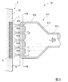
図1に示すように、本実施形態に係るレーザ発振冷却装置100は、レーザ励起光Z1を発する発光部1と、入射されたレーザ励起光Z1を励起してレーザ光Z2を発するレーザ励起部2と、レーザ励起部2を冷却するための冷却部10と、この冷却部10の動作を制御する制御部6と、を備えている。
[First embodiment]
Hereinafter, a first embodiment of the present invention will be described with reference to the drawings.
As shown in FIG. 1, a laser
(レーザ励起部)
発光部1は、レーザ励起部2に向かってレーザ励起光Z1を照射することが可能な位置に配される。レーザ励起部2は、例えばサファイヤやYAG(Yttrium Aluminum Garnet)結晶を有する媒質部21と、この媒質部21に対して熱的に接続されたヒートシンク部22と、を有している。
このレーザ励起部2における媒質部21に入射されたレーザ励起光Z1の数10%程度が、レーザ励起媒質によって励起されてレーザ光Z2となる。レーザ光Z2は、外部に取り出されて、例えばレーザ加工等の用に供される。
(Laser excitation part)
The light emitting unit 1 is disposed at a position where the laser excitation light Z1 can be irradiated toward the
About several tens of percent of the laser excitation light Z1 incident on the
このレーザ励起部2の媒質部21によってレーザ光Z2が得られる一方で、レーザ光Z2として取り出された成分を除く成分は、おおむね熱に変換される。この熱により、レーザ励起部2は局所的に発熱する。上述したように媒質部21にはヒートシンク部22が熱的に接続されていることから、媒質部21で生じた発熱は、ただちにヒートシンク部22に伝達される。
While the laser beam Z2 is obtained by the
さらに、このレーザ励起部2には、温度計測部5が設けられている。温度計測部5は、レーザ励起部2における媒質部21の温度を計測して数値化する装置である。温度計測部5としては例えば温度センサ等が用いられる。
Further, the
このように構成されたレーザ励起部2は、少なくとも一部(ヒートシンク部22)が、冷温状態に保たれたクライオスタットCの内部に露出している。すなわち、レーザ励起部2は、クライオスタットCの壁面を挟んで、該クライオスタットCの内外に臨んでいる。特に、クライオスタットCの内部を臨む面(ヒートシンク部22)は、平面状に形成されている。本実施形態では、このヒートシンク部22の全体にわたっておおむね均一の熱量が放射される場合について説明する。すなわち、本実施形態に係るヒートシンク部22は、その全体が発熱領域Sとされている。
At least a part (heat sink part 22) of the
(冷却部)
ここで、レーザ励起部2によって励起されるレーザの発振限界(最大出力:W)は、レーザ励起媒質が低温であるほど、高くなる。したがって、レーザ励起部2を冷却するために、本実施形態に係るレーザ発振冷却装置100は冷却部10を備えている。冷却部10は、極低温液体Lを用いてレーザ励起部2を冷却する装置である。冷却部10は、この極低温液体Lを収容可能な収容タンク3と、収容タンク3の内部を加圧する加圧部31と、収容タンク3中の極低温液体Lを取り出してレーザ励起部2に供給する噴射供給部4と、を備えている。
(Cooling section)
Here, the oscillation limit (maximum output: W) of the laser pumped by the
極低温液体Lとして、本実施形態では液体窒素を用いた例について説明する。収容タンク3は、液体窒素を液相状態で安定的に収容することが可能な容器である。すなわち、収容タンク3の内部は極低温に保たれている。この収容タンク3の内部の圧力は、加圧部31によって調整することができる。加圧部31としては、外部の圧力供給源(不図示)に接続された圧力弁が好適に用いられる。さらに、収容タンク3には、内部の圧力を計測するための圧力計測部51が設けられている。圧力計測部51の例としては、圧力値を電気信号として外部に出力することが可能な圧力計や圧力センサ等が挙げられる。
In this embodiment, an example using liquid nitrogen as the cryogenic liquid L will be described. The storage tank 3 is a container that can stably store liquid nitrogen in a liquid phase state. That is, the inside of the storage tank 3 is kept at a very low temperature. The pressure inside the storage tank 3 can be adjusted by the pressurizing
収容タンク3の体積が一定であることから、加圧部31によって収容タンク3内部の圧力を上げることで、極低温液体Lの温度を下げることができる。反対に、収容タンク3内部の圧力を下げることで、極低温液体Lの温度を上げることができる。
Since the volume of the storage tank 3 is constant, the temperature of the cryogenic liquid L can be lowered by increasing the pressure inside the storage tank 3 by the pressurizing
特に、本実施形態に係る冷却部10では、加圧部31によって収容タンク3の内部の圧力を下げ続けることで、収容タンク3内部の極低温液体Lをサブクール状態に維持する。例えば、極低温液体Lとして液体窒素を使用する場合、大気圧下における液体窒素の飽和温度は−196℃であるが、サブクール状態にある場合、飽和温度を−196℃よりも低い値で維持することができる。また、加圧部31によって収容タンク3内部の圧力を調整することにより、サブクール状態にある極低温液体Lのサブクール度、すなわち飽和温度との差分をも調整することができる。
In particular, in the
噴射供給部4は、レーザ励起部2のヒートシンク部22に対して極低温液体Lを噴射するための装置である。噴射供給部4は、極低温液体Lを噴射する噴射ノズル41と、この噴射ノズル41と収容タンク3とを接続する供給管42と、供給管42の中途に設けられた流量調整部43と、を備えている。
The jet supply unit 4 is a device for jetting the cryogenic liquid L onto the
噴射ノズル41の先端部には、複数の噴射口416が二次元的に配列されている。供給管42を介して収容タンク3から噴射ノズル41に供給された極低温液体Lはこの噴射口416を通じて外部に噴射される。噴射ノズル41から噴射される極低温液体Lの流量は、流量調整部43によって調整することができる。流量調整部43としては、例えば絞り弁や流量調整弁等のように開度を調整することが可能な弁が好適に用いられる。
なお、以下の説明では、噴射ノズル41から極低温液体Lが噴射される噴射方向と呼ぶ。さらに、この噴射方向において、極低温液体Lが流れてくる側を上流側と呼び、上流側と反対の側(極低温液体Lが流れ去る側)を下流側と呼ぶ。
A plurality of
In the following description, it is referred to as an ejection direction in which the cryogenic liquid L is ejected from the
次に、噴射ノズル41の詳細な構成について図3と図4を参照して説明する。図3に示すように、本実施形態に係る噴射ノズル41は、供給管42と接続されるとともに、レーザ励起部2(ヒートシンク部22)に対向する面(噴射面415)に複数の噴射口416が形成されている。
Next, a detailed configuration of the
ノズル本体411は、供給管42の端部と接続される接続部412と、この接続部412の下流側で一体に設けられる拡径部413、及び噴射部414と、を有している。接続部412、拡径部413、噴射部414はいずれも管状をなすことで、内部に極低温液体Lが流通する流路を形成する。
The
拡径部413の上流側の端部は、接続部412の下流側の端部と連通されている。さらに、上流側から下流側に向かうに従って、拡径部413の開口寸法(流路断面積)は次第に大きくなる。言い換えれば、拡径部413はおおむね漏斗状をなしている。
The upstream end portion of the
噴射部414は、拡径部413の下流側に一体に設けられるとともに、その下流側の面である噴射面415には、比較的に小径の噴射口416が複数形成されている。さらに、本実施形態では、この噴射面415は、上記のヒートシンク部22に対しておおむね平行をなす二次元平面上に広がっている。言い換えると、ヒートシンク部22と噴射面415とは、ヒートシンク部22(又は噴射面415)の広がる面方向の全体にかけて一定の距離だけ互いに離間している。
The
以上の構成により、供給管42を通じて噴射ノズル41に流入した極低温液体Lは、互いに連通する接続部412,拡径部413,噴射部414を経て、複数の噴射口416から外部に向かって噴射される。なお、これら噴射口416の設けられる個数や個々の開口形状は、除熱の対象であるレーザ励起部2の面積に応じて適宜に決定される。
With the above-described configuration, the cryogenic liquid L that has flowed into the
続いて、上記複数の噴射口416の配置について、図4を参照して説明する。同図に示すように、本実施形態では、噴射面415はおおむね矩形をなしている。なお、噴射面415の形状は、レーザ励起部2の外形に応じて適宜に決定されてよい。上記の噴射方向下流側から見た場合、この噴射面415には、複数の噴射口416が格子状に配列されている。
Next, the arrangement of the plurality of
より詳細には、矩形をなす噴射面415上において、複数の噴射口416の一部は、特定の一方向(第一方向d1)に間隔を空けて配列された群(配列群m)を形成している。さらに、この第一方向d1に直交する方向(第二方向d2)に間隔を空けて複数の配列群mが設けられている。
More specifically, on the
特に、本実施形態では、上記の配列群mのうち、互いに隣り合う一対の配列群mにおける噴射口416のうち、一方の配列群mの噴射口416と、他方の配列群mの噴射口416との位置が、第一方向d1において同一とされている。すなわち、複数の噴射口416は、噴射面415上で格子状に配列されている。なお、ここで言う「同一」とは、必ずしも完全に同一である必要はなく、加工による誤差等は許容される。
In particular, in the present embodiment, out of the injection holes 416 in the pair of arrangement groups m adjacent to each other among the arrangement group m, the
さらに、これら複数の噴射口416における各部の寸法は以下の条件を充足するように設定されている。具体的には、噴射口416の開口径をdとし、噴射面415からヒートシンク部22までの離間寸法をHとし、互いに隣り合う2つの噴射口416同士の離間距離をPとしたとき、以下の(1)式、及び(2)式の関係が成立する。
3≦H/d≦7 ・・・(1)
2≦P/d≦10 ・・・(2)
Furthermore, the dimension of each part in these
3 ≦ H / d ≦ 7 (1)
2 ≦ P / d ≦ 10 (2)
特に、上記P/dの値は、式(2)に示す数値範囲(2以上10以下)のうち、2以上5未満に設定されることが最も望ましい。 In particular, the value of P / d is most desirably set to 2 or more and less than 5 in the numerical range (2 or more and 10 or less) shown in Expression (2).
(制御部)
制御部6は、レーザ励起部2の温度に応じて極低温液体Lのサブクール度を調整し、最適な冷却効果を得るための装置である。図2に示すように制御部6は、外部から電気信号としての各種計測値が入力されるとともに、計測値と対照すべきデータを記憶する入力記憶部61と、この入力記憶部61に入力された入力値に基づいて演算を行う演算部62と、演算部62の出力する演算値に基づいて外部に指示値を出力する指示部63と、を有している。
(Control part)
The
ここで、極低温液体Lのサブクール度は、収容タンク3内の圧力を調整することで変化させることができる。例えば、収容タンク3内部の圧力を上げた場合、極低温液体Lのサブクール度を上げることができる。一方で、収容タンク3内部の圧力を下げた場合、極低温液体Lのサブクール度を下げることができる。 Here, the subcooling degree of the cryogenic liquid L can be changed by adjusting the pressure in the storage tank 3. For example, when the pressure inside the storage tank 3 is increased, the subcooling degree of the cryogenic liquid L can be increased. On the other hand, when the pressure inside the storage tank 3 is lowered, the subcool degree of the cryogenic liquid L can be lowered.
さらに、レーザ励起部2を冷却するための極低温液体Lのサブクール度が増加するほど、極低温液体Lの限界熱流束は上昇する。すなわち、サブクール度が増加するほど、レーザ励起部2におけるレーザ発振限界値は向上する。したがって、ある値のレーザ出力を得ている場合、当該レーザ出力を維持するために必要な最低限のサブクール度(目標サブクール度)が存在する。
本実施形態に係る制御部6では、温度値として計測されたレーザ出力に基づいて、必要とされる目標サブクール度を演算部62が演算によって求め、この目標サブクール度を目指して指示部63が加圧部31に対して指示信号を送り、収容タンク3内部の圧力を調整する。すなわち、この場合、制御部6は加圧部31による加圧力を調整することで、極低温液体Lのサブクール度を変化させるための装置として動作する。
Furthermore, the critical heat flux of the cryogenic liquid L increases as the subcooling degree of the cryogenic liquid L for cooling the
In the
さらに、以上のような構成によれば、複数配列されたそれぞれの噴射口416から極低温液体Lが噴射される。これにより、比較的大きな面積を冷却するに際して、例えば大口径の噴射口416を1つのみ設けた場合に比べて、極低温液体Lの使用量を低減できる。言い換えれば、上記の構成によれば、レーザ励起部2の冷却に供されずに流れ去る極低温液体Lの量(余剰量)を低減し、単位流量当たりの冷却能力(除熱量)を最適化することができる。
Furthermore, according to the above configuration, the cryogenic liquid L is ejected from each of the plurality of
さらに、レーザ励起部2に噴射された極低温液体Lは、該レーザ励起部2の表面に沿って高速で流動する高速液膜を形成する。具体的には図2等に示すように、各噴射口416から噴射された極低温液体Lの噴流は、ヒートシンク部22に衝突することで該ヒートシンク部22の表面に沿って流れ、高速液膜を形成する。これにより、ヒートシンク部22の表面では、高速で流通する極低温液体Lが膜状となって常態的に熱交換を行う。これにより、レーザ励起部2の発熱をさらに効果的に除熱することができる。
Further, the cryogenic liquid L ejected to the
加えて、上述したように、本実施形態ではサブクール状態の極低温液体Lによって高速液膜を形成することから、極低温液体L中における核沸騰が維持された状態となる。言い換えれば、この極低温液体L中で膜沸騰が生じる可能性が低減されている。これにより、極低温液体Lの過度な蒸発が抑制されるため、レーザ励起部2に対する十分な冷却能力を得ることができる。
In addition, as described above, since the high-speed liquid film is formed by the subcooled cryogenic liquid L in the present embodiment, the nucleate boiling in the cryogenic liquid L is maintained. In other words, the possibility of film boiling in the cryogenic liquid L is reduced. Thereby, since excessive evaporation of the cryogenic liquid L is suppressed, sufficient cooling capacity for the
さらに、本実施形態では、複数の噴射口416は、極低温液体Lの噴射方向から見て、噴射方向に直交する第一方向d1に間隔を空けて配列された配列群mを形成するとともに、この配列群mは、第一方向d1に直交する第二方向d2に間隔を空けて複数設けられている。すなわち、複数の噴射口416は、噴射面415上で格子状をなしている。
Furthermore, in the present embodiment, the plurality of
上述のような構成によれば、レーザ励起部2の表面上(ヒートシンク部22上)で形成される極低温液体Lの高速液膜の厚さを、該表面の全体にわたっておおむね均一化することができる。これにより、ヒートシンク部22における除熱量の偏りを抑制することができる。
According to the above-described configuration, the thickness of the high-speed liquid film of the cryogenic liquid L formed on the surface of the laser excitation unit 2 (on the heat sink unit 22) can be made substantially uniform over the entire surface. it can. Thereby, the bias | inclination of the heat removal amount in the
加えて、本実施形態では、複数の噴射口416の寸法は、上記式(1)、式(2)に示す関係を満たすように設定されている。
In addition, in this embodiment, the dimensions of the plurality of
ここで、本実施形態のように、極低温液体Lの噴流による発熱体(レーザ励起部2)の冷却特性(冷却能力)は、極低温液体Lの流速が高いほど大きくなることが知られている。特にP/dの値は、噴射口416における極低温液体Lの流速を最適化する上で支配的な指標であることが知られている。例えば、このP/dの値を式(2)の範囲外に設定した場合、極低温液体Lの流速は低下してしまい、レーザ励起部2に対する冷却能力を十分に確保できない可能性がある。しかしながら、本実施形態では上記の各条件を満たすことにより、極低温液体Lの流速を最大化することができる。
Here, as in this embodiment, it is known that the cooling characteristic (cooling capacity) of the heating element (laser excitation unit 2) by the jet of the cryogenic liquid L increases as the flow velocity of the cryogenic liquid L increases. Yes. In particular, it is known that the value of P / d is a dominant index in optimizing the flow rate of the cryogenic liquid L at the
さらに、このような構成によれば、レーザ励起部2を十分に冷却することができるとともに、レーザ励起部2において除熱を要する領域の面積が広くなった場合であっても、必要な極低温液体Lの流量の増加を抑制することができる。
Furthermore, according to such a configuration, the
つまり、上記の各条件(式(1)、式(2))の関係を満たす噴射ノズル41を用いることにより、極低温液体Lの流速の最大化と、極低温液体Lの使用量の削減とを両立した上で、十分に良好な冷却能力を得ることができる。
That is, by using the
以上、本発明の第一実施形態について図面を参照して説明した。しかしながら、上記の実施形態はあくまで一例に過ぎず、本発明の要旨を逸脱しない限りにおいて種々の変更や改修を加えることが可能である。
例えば、上記実施形態では、噴射面415が概ね矩形に形成された例について説明した。しかしながら、噴射面415の形状は矩形に限定されず、円形や楕円形であってもよく、さらには三角形や五角形であってもよい。要するに、噴射面415の形状は、該噴射面415が対向するレーザ励起部2(ヒートシンク部22)の全体を覆うことができる限りにおいては任意に決定されてよい。
The first embodiment of the present invention has been described above with reference to the drawings. However, the above embodiment is merely an example, and various changes and modifications can be added without departing from the gist of the present invention.
For example, in the above embodiment, an example in which the
〔第二実施形態〕
次に、本発明の第二実施形態について、図5を参照して説明する。なお、上記第一実施形態と同様の構成や部材については同一の符号を付し、詳細な説明を省略する。同図に示すように、本実施形態に係るレーザ発振冷却装置100では、噴射ノズル41の内部に多孔部材417が設けられている。この多孔部材417は、より詳細には拡径部413と噴射部414との間の境界面内に設けられるおおむね板状の部材である。
[Second Embodiment]
Next, a second embodiment of the present invention will be described with reference to FIG. In addition, about the structure and member similar to said 1st embodiment, the same code | symbol is attached | subjected and detailed description is abbreviate | omitted. As shown in the figure, in the laser
さらに、多孔部材417には極低温液体Lの噴射方向に貫通する複数の孔部418が形成されている。これら複数の孔部418は、互いに同一の形状及び寸法を有している。本実施形態では、これら孔部418はいずれも略円形の断面形状(噴射方向における断面形状)を有している。
Further, the
上記のような構成により、接続部412及び拡径部413を経て流入した極低温液体Lは、多孔部材417の上流側の領域(すなわち、拡径部413の内部)で一定時間だけ滞留した後、多孔部材417の孔部418を通過する。これにより、多孔部材417の下流側の領域(すなわち、噴射部414の内部)における極低温液体Lが整流される。言い換えると、多孔部材417の延在する領域のおおむね全体にかけて、極低温液体Lの流量を均一化することができる。これにより、それぞれの噴射口416から噴射される極低温液体Lの流量を均一化することができるため、ヒートシンク部22上における除熱量にムラが生じる可能性を低減することができる。
With the configuration as described above, after the cryogenic liquid L that has flowed in through the
[第三実施形態]
続いて、本発明の第三実施形態について、図6を参照して説明する。なお、上記の各実施形態と同様の構成や部材については同一の符号を付し、詳細な説明を省略する。同図に示すように、本実施形態に係るレーザ発振冷却装置100では、複数の噴射口416の配置が上記の各実施形態とは異なっている。
[Third embodiment]
Next, a third embodiment of the present invention will be described with reference to FIG. In addition, about the structure and member similar to said each embodiment, the same code | symbol is attached | subjected and detailed description is abbreviate | omitted. As shown in the figure, in the laser
具体的には、本実施形態では、互いに隣り合う一対の噴射口416の配列群mのうち、一方の配列群mにおける噴射口416の位置と、他方の配列群mにおける噴射口416の位置とが、上記の第一方向d1で異なっている。言い換えれば、これら複数の噴射口416は噴射面415上で千鳥状(staggered)に配列されている。
Specifically, in the present embodiment, among the array group m of a pair of
このような構成によれば、レーザ励起部2の表面上で形成される極低温液体Lの高速液膜の厚さを、該表面の全体にわたってさらに均一化することができる。さらに、このような構成によれば、一定の面積の平面内により多くの噴射口416を高い密度で設けることができる。したがって、ヒートシンク部22における除熱量をさらに大きくすることができるとともに、極低温液体Lの使用量の増大を抑制することができる。
According to such a configuration, the thickness of the high-speed liquid film of the cryogenic liquid L formed on the surface of the
さらに、本実施形態における複数の噴射口416についても、上記式(1)、式(2)の各条件を充足するように各寸法を設定することが可能である。
Furthermore, each dimension can also be set so that each condition of said Formula (1) and Formula (2) is satisfied also about the
加えて、本実施形態における噴射ノズル41に対して、上記の第二実施形態に記載された多孔部材417を設けることも可能である。これにより、ヒートシンク部22上における除熱量にムラが生じる可能性を低減することができる。
In addition, it is also possible to provide the
[第四実施形態]
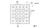
さらに、本発明の第三実施形態について、図7を参照して説明する。なお、上記の各実施形態と同様の構成や部材については同一の符号を付し、詳細な説明を省略する。同図に示すように、本実施形態に係るレーザ発振冷却装置100では、レーザ励起部2における発熱量の分布と、複数の噴射口416の配置とが上記の各実施形態とは異なっている。
[Fourth embodiment]
Furthermore, a third embodiment of the present invention will be described with reference to FIG. In addition, about the structure and member similar to said each embodiment, the same code | symbol is attached | subjected and detailed description is abbreviate | omitted. As shown in the figure, in the laser
詳細には、本実施形態では、レーザ励起部2におけるヒートシンク部22のうち、その一部の領域における発熱量が、他の領域に比べて相対的に高くなっている。すなわち、本実施形態では、ヒートシンク部22がなす矩形の領域のうち、その重心を含む中央の領域が、発熱領域Sとされている。
Specifically, in the present embodiment, the heat generation amount in a part of the
さらに、本実施形態に係る噴射ノズル41では、複数の噴射口416のうち、発熱領域Sに相対的に近い噴射口416になるほど開口径が大きく、発熱領域Sから相対的に遠い噴射口416になるほど開口径が小さく設定されている。より具体的には、上記の噴射方向から見て、発熱領域Sと重なる領域では、噴射口416の開口径が相対的に大きく設定されている。一方で、噴射面415上でこの発熱領域Sを除く領域と重なる領域では、噴射口416の開口径が相対的に小さく設定されている。
Furthermore, in the
このような構成によれば、発熱領域Sに臨む噴射口416からは相対的に多くの極低温液体Lが噴射される。すなわち、発熱領域Sに対して集中的に、より多くの極低温液体Lを噴射することができる。これにより、レーザ励起部2のヒートシンク部22における温度分布をさらに均一化することができる。
According to such a configuration, a relatively large amount of the cryogenic liquid L is ejected from the
特に、レーザ励起部2の発熱領域Sが予め特定されている場合には、上記の構成を採ることで、よりレーザ励起部2における除熱量をより高い精度でコントロールすることができる。
In particular, when the heat generation region S of the
なお、本実施形態における噴射ノズル41に対して、上記の第二実施形態に記載された多孔部材417を設けることも可能である。これにより、ヒートシンク部22上における除熱量にムラが生じる可能性を低減することができる。
In addition, it is also possible to provide the
さらに、上記の実施形態、及び図7の例では、発熱領域Sの臨む噴射口416同士で開口径が互いに同一である構成について説明した。しかしながら、これら噴射口416同士の開口径は、発熱領域S内であっても互いに同一である必要はなく、発熱領域Sの中心部側から縁部側に向かうに従って次第に開口径が小さくなるように、又は大きくなるように形成されていてもよい。すなわち、発熱領域S内におけるさらに微視的な温度分布が予め得られている場合、この温度分布に対応するように、噴射口416の開口径を設定することが望ましい。具体的には、温度が相対的に高い領域に臨む噴射口416の開口径は相対的に大きく設定され、反対に温度が相対的に低い領域に臨む噴射口416の開口径は相対的に小さく設定されることが望ましい。
以上のような構成を採ることで、ヒートシンク部22における温度分布をさらに高い精度で均一化することができる。
Furthermore, in the above embodiment and the example of FIG. 7, the configuration in which the opening diameters of the
By adopting the above configuration, the temperature distribution in the
1…発光部 2…レーザ励起部 3…収容タンク 4…噴射供給部 5…温度計測部 6…制御部 10…冷却部 21…媒質部 22…ヒートシンク部 31…加圧部 41…噴射ノズル 42…供給管 43…流量調整部 44…流量計測部 51…圧力計測部 61…入力記憶部 62…演算部 63…指示部 100…レーザ発振冷却装置 411…ノズル本体 412…接続部 413…拡径部 414…噴射部 415…噴射面 416…噴射口 417…多孔部材 418…孔部 C…クライオスタット d1…第一方向 d2…第二方向 L…極低温液体 m…配列群 S…発熱領域 Z1…レーザ励起光 Z2…レーザ光
DESCRIPTION OF SYMBOLS 1 ...
Claims (7)
前記レーザ励起光を励起してレーザ光を発するとともに、局所的に発熱する発熱領域を有するレーザ励起部と、
極低温液体を収容可能な収容タンクと、
前記収容タンクの内部を加圧することで前記極低温液体をサブクール状態とする加圧部と、
二次元的に複数配列された噴射口からサブクール状態の前記極低温液体を前記レーザ励起部に噴射することで該レーザ励起部を除熱する噴射供給部と、
を備えるレーザ発振冷却装置。 A light emitting unit for emitting laser excitation light;
Exciting the laser excitation light to emit laser light, and a laser excitation unit having a heat generation region that generates heat locally,
A storage tank capable of storing a cryogenic liquid;
A pressurizing unit that makes the cryogenic liquid into a subcooled state by pressurizing the inside of the storage tank;
An injection supply unit that removes heat from the laser excitation unit by injecting the cryogenic liquid in a subcooled state into the laser excitation unit from a plurality of two-dimensionally arranged injection ports;
A laser oscillation cooling device comprising:
前記配列群は、前記第一方向に直交する第二方向に間隔を空けて複数設けられる請求項1に記載のレーザ発振冷却装置。 The plurality of injection ports form an array group arranged at intervals in a first direction orthogonal to the injection direction as seen from the injection direction of the cryogenic liquid,
The laser oscillation cooling device according to claim 1, wherein a plurality of the array groups are provided at intervals in a second direction orthogonal to the first direction.
3≦H/d≦7 ・・・(1)
2≦P/d≦10 ・・・(2) When the opening diameter of the injection port is d, the separation dimension from the injection supply unit to the laser excitation unit is H, and the separation distance between the two adjacent injection ports is P, the following (1) The laser oscillation cooling device according to any one of claims 1 to 4, wherein the relationship between the formula and the formula (2) is established.
3 ≦ H / d ≦ 7 (1)
2 ≦ P / d ≦ 10 (2)
前記極低温液体の噴射方向から見て、前記噴射口の上流側に配置されるとともに、前記噴射方向に貫通する複数の孔部が形成された多孔部材を備える請求項1から6のいずれか一項に記載のレーザ発振冷却装置。 The injection supply unit
7. The device according to claim 1, further comprising a porous member that is disposed on the upstream side of the injection port as viewed from the injection direction of the cryogenic liquid and has a plurality of holes that penetrate in the injection direction. The laser oscillation cooling device according to item.
Priority Applications (4)
| Application Number | Priority Date | Filing Date | Title |
|---|---|---|---|
| JP2015057389A JP6493832B2 (en) | 2015-03-20 | 2015-03-20 | Laser oscillation cooling device |
| EP15886492.6A EP3244495B1 (en) | 2015-03-20 | 2015-11-20 | Laser oscillation system with a cooling device |
| US15/550,896 US10014646B2 (en) | 2015-03-20 | 2015-11-20 | Laser oscillation cooling device |
| PCT/JP2015/082705 WO2016151940A1 (en) | 2015-03-20 | 2015-11-20 | Laser oscillation cooling device |
Applications Claiming Priority (1)
| Application Number | Priority Date | Filing Date | Title |
|---|---|---|---|
| JP2015057389A JP6493832B2 (en) | 2015-03-20 | 2015-03-20 | Laser oscillation cooling device |
Publications (2)
| Publication Number | Publication Date |
|---|---|
| JP2016178207A true JP2016178207A (en) | 2016-10-06 |
| JP6493832B2 JP6493832B2 (en) | 2019-04-03 |
Family
ID=56977134
Family Applications (1)
| Application Number | Title | Priority Date | Filing Date |
|---|---|---|---|
| JP2015057389A Active JP6493832B2 (en) | 2015-03-20 | 2015-03-20 | Laser oscillation cooling device |
Country Status (4)
| Country | Link |
|---|---|
| US (1) | US10014646B2 (en) |
| EP (1) | EP3244495B1 (en) |
| JP (1) | JP6493832B2 (en) |
| WO (1) | WO2016151940A1 (en) |
Cited By (1)
| Publication number | Priority date | Publication date | Assignee | Title |
|---|---|---|---|---|
| JP7382498B2 (en) | 2019-10-16 | 2023-11-16 | テラダイオード, インコーポレーテッド | Packages for high power laser devices |
Families Citing this family (4)
| Publication number | Priority date | Publication date | Assignee | Title |
|---|---|---|---|---|
| US11095091B2 (en) * | 2016-06-20 | 2021-08-17 | TeraDiode, Inc. | Packages for high-power laser devices |
| US10490972B2 (en) * | 2016-06-20 | 2019-11-26 | TeraDiode, Inc. | Packages for high-power laser devices |
| US10809014B1 (en) * | 2018-03-30 | 2020-10-20 | Northrop Grumman Systems Corporation | Thermal storage with bladder tank |
| US11121061B2 (en) * | 2018-11-20 | 2021-09-14 | Toyota Motor Engineering & Manufacturing North America, Inc. | Cooling chip structures having a jet impingement system and assembly having the same |
Citations (6)
| Publication number | Priority date | Publication date | Assignee | Title |
|---|---|---|---|---|
| JPS56164299A (en) * | 1980-04-17 | 1981-12-17 | Union Carbide Corp | Method of and apparatus for feeding liquid cooling agent |
| JPH05141813A (en) * | 1991-11-18 | 1993-06-08 | Mitsubishi Motors Corp | Expansion valve |
| JPH10294520A (en) * | 1997-04-21 | 1998-11-04 | Nec Corp | Solid state laser system |
| US20040028094A1 (en) * | 2001-11-13 | 2004-02-12 | Raytheon Company | Multi-jet impingement cooled slab laser pumphead and method |
| JP2011038581A (en) * | 2009-08-10 | 2011-02-24 | Taiyo Nippon Sanso Corp | Liquefied gas injecting device |
| JP2014022568A (en) * | 2012-07-18 | 2014-02-03 | Osaka Univ | Laser medium unit, laser amplifier and laser oscillator and cooling method |
Family Cites Families (10)
| Publication number | Priority date | Publication date | Assignee | Title |
|---|---|---|---|---|
| JP2544616B2 (en) * | 1987-03-31 | 1996-10-16 | ホ−ヤ株式会社 | Solid-state laser device |
| JP2961072B2 (en) * | 1995-06-23 | 1999-10-12 | 株式会社神戸製鋼所 | Oxygen and nitrogen liquefaction equipment |
| JPH10190094A (en) | 1996-12-25 | 1998-07-21 | Ushio Inc | Excitation section of solid laser device |
| US6195372B1 (en) * | 1997-08-19 | 2001-02-27 | David C. Brown | Cryogenically-cooled solid-state lasers |
| JPH11295772A (en) | 1998-04-15 | 1999-10-29 | Sony Corp | Laser beam generator and generating method thereof |
| US6993926B2 (en) * | 2001-04-26 | 2006-02-07 | Rini Technologies, Inc. | Method and apparatus for high heat flux heat transfer |
| JP4464914B2 (en) * | 2004-12-22 | 2010-05-19 | 学校法人東京理科大学 | Boiling cooling method, boiling cooling device, flow channel structure, and application product thereof |
| JP2008027780A (en) * | 2006-07-21 | 2008-02-07 | Sumitomo Electric Ind Ltd | Liquid-coolant circulation cooling system |
| US7532652B2 (en) * | 2007-02-20 | 2009-05-12 | The Boeing Company | Laser thermal management systems and methods |
| JP6145080B2 (en) | 2014-09-29 | 2017-06-07 | 三菱重工業株式会社 | Laser oscillation cooling device |
-
2015
- 2015-03-20 JP JP2015057389A patent/JP6493832B2/en active Active
- 2015-11-20 EP EP15886492.6A patent/EP3244495B1/en active Active
- 2015-11-20 US US15/550,896 patent/US10014646B2/en active Active
- 2015-11-20 WO PCT/JP2015/082705 patent/WO2016151940A1/en active Application Filing
Patent Citations (6)
| Publication number | Priority date | Publication date | Assignee | Title |
|---|---|---|---|---|
| JPS56164299A (en) * | 1980-04-17 | 1981-12-17 | Union Carbide Corp | Method of and apparatus for feeding liquid cooling agent |
| JPH05141813A (en) * | 1991-11-18 | 1993-06-08 | Mitsubishi Motors Corp | Expansion valve |
| JPH10294520A (en) * | 1997-04-21 | 1998-11-04 | Nec Corp | Solid state laser system |
| US20040028094A1 (en) * | 2001-11-13 | 2004-02-12 | Raytheon Company | Multi-jet impingement cooled slab laser pumphead and method |
| JP2011038581A (en) * | 2009-08-10 | 2011-02-24 | Taiyo Nippon Sanso Corp | Liquefied gas injecting device |
| JP2014022568A (en) * | 2012-07-18 | 2014-02-03 | Osaka Univ | Laser medium unit, laser amplifier and laser oscillator and cooling method |
Cited By (1)
| Publication number | Priority date | Publication date | Assignee | Title |
|---|---|---|---|---|
| JP7382498B2 (en) | 2019-10-16 | 2023-11-16 | テラダイオード, インコーポレーテッド | Packages for high power laser devices |
Also Published As
| Publication number | Publication date |
|---|---|
| EP3244495A1 (en) | 2017-11-15 |
| US10014646B2 (en) | 2018-07-03 |
| US20180026416A1 (en) | 2018-01-25 |
| EP3244495A4 (en) | 2018-04-18 |
| JP6493832B2 (en) | 2019-04-03 |
| EP3244495B1 (en) | 2019-12-25 |
| WO2016151940A1 (en) | 2016-09-29 |
Similar Documents
| Publication | Publication Date | Title |
|---|---|---|
| JP6493832B2 (en) | Laser oscillation cooling device | |
| US8550372B2 (en) | Full coverage spray and drainage system and method for orientation-independent removal of high heat flux | |
| US9313921B2 (en) | Chip stack structures that implement two-phase cooling with radial flow | |
| JP6003323B2 (en) | LASER MEDIUM UNIT, LASER AMPLIFIER, LASER OSCILLATOR, AND COOLING METHOD | |
| Xie et al. | Multi-nozzle array spray cooling for large area high power devices in a closed loop system | |
| US20080060792A1 (en) | High performance integrated mlc cooling device for high power density ics and method for manufacturing | |
| JPH08213674A (en) | Method and equipment for collision cooling of laser rod | |
| Salman et al. | Experimental investigation of the impact of geometrical surface modification on spray cooling heat transfer performance in the non-boiling regime | |
| Hong et al. | Confined jet array impingement boiling of subcooled aqueous ethylene glycol solution | |
| US20140190669A1 (en) | Cooling head and electronic apparatus | |
| JP6145080B2 (en) | Laser oscillation cooling device | |
| JP2008244495A (en) | Evaporation cooling method, evaporation cooling device, flow path structure, and its application product | |
| JP2004354185A (en) | Bubble generation device used for doppler type ultrasonic flowmeter, and doppler type ultrasonic flowmeter | |
| JP2012132613A (en) | Loop type heat pipe and information processing apparatus | |
| US20120089090A1 (en) | Fluid ejection device and medical device | |
| US10236655B2 (en) | Solid laser amplification device | |
| US9398721B2 (en) | Cooling fluid flow passage matrix for electronics cooling | |
| KR20210027429A (en) | Steam bypass conduit | |
| JP2009129971A (en) | Heat transfer apparatus | |
| WO2015141430A1 (en) | Laser-oscillation cooling device | |
| US10634438B2 (en) | Cooling plate and information processing device | |
| JP7151457B2 (en) | Piston pump, boost liquid supply system and liquid injection device | |
| JP6699900B2 (en) | Rectifier | |
| JP2015185737A (en) | cooler | |
| JP7382498B2 (en) | Packages for high power laser devices |
Legal Events
| Date | Code | Title | Description |
|---|---|---|---|
| A621 | Written request for application examination |
Free format text: JAPANESE INTERMEDIATE CODE: A621 Effective date: 20180220 |
|
| A131 | Notification of reasons for refusal |
Free format text: JAPANESE INTERMEDIATE CODE: A131 Effective date: 20181030 |
|
| RD03 | Notification of appointment of power of attorney |
Free format text: JAPANESE INTERMEDIATE CODE: A7423 Effective date: 20181109 |
|
| A521 | Request for written amendment filed |
Free format text: JAPANESE INTERMEDIATE CODE: A523 Effective date: 20181225 |
|
| TRDD | Decision of grant or rejection written | ||
| A01 | Written decision to grant a patent or to grant a registration (utility model) |
Free format text: JAPANESE INTERMEDIATE CODE: A01 Effective date: 20190205 |
|
| A61 | First payment of annual fees (during grant procedure) |
Free format text: JAPANESE INTERMEDIATE CODE: A61 Effective date: 20190222 |
|
| R150 | Certificate of patent or registration of utility model |
Ref document number: 6493832 Country of ref document: JP Free format text: JAPANESE INTERMEDIATE CODE: R150 |