JP2016147618A - Motorcycle - Google Patents
Motorcycle Download PDFInfo
- Publication number
- JP2016147618A JP2016147618A JP2015026458A JP2015026458A JP2016147618A JP 2016147618 A JP2016147618 A JP 2016147618A JP 2015026458 A JP2015026458 A JP 2015026458A JP 2015026458 A JP2015026458 A JP 2015026458A JP 2016147618 A JP2016147618 A JP 2016147618A
- Authority
- JP
- Japan
- Prior art keywords
- case
- chain
- motorcycle
- reinforcing plate
- chain case
- Prior art date
- Legal status (The legal status is an assumption and is not a legal conclusion. Google has not performed a legal analysis and makes no representation as to the accuracy of the status listed.)
- Granted
Links
Images


Classifications
-
- B—PERFORMING OPERATIONS; TRANSPORTING
- B62—LAND VEHICLES FOR TRAVELLING OTHERWISE THAN ON RAILS
- B62J—CYCLE SADDLES OR SEATS; AUXILIARY DEVICES OR ACCESSORIES SPECIALLY ADAPTED TO CYCLES AND NOT OTHERWISE PROVIDED FOR, e.g. ARTICLE CARRIERS OR CYCLE PROTECTORS
- B62J13/00—Guards for chain, chain drive or equivalent drive, e.g. belt drive
- B62J13/02—Guards for chain, chain drive or equivalent drive, e.g. belt drive shielding only the upper run of the chain or the like
Landscapes
- Engineering & Computer Science (AREA)
- Mechanical Engineering (AREA)
- Axle Suspensions And Sidecars For Cycles (AREA)
Abstract
Description
本発明は自動二輪車に関し、特に、チェーンケースが改善された自動二輪車に関する。 The present invention relates to a motorcycle, and more particularly, to a motorcycle with an improved chain case.
従来の自動二輪車の構造においては、パワーユニットの駆動力を後輪に伝達するチェーンを有し、このチェーンを覆うケースが設けられた構造のものがある(例えば、特許文献1参照)。特許文献1に記載されている構造においては、ドライブスプロケットとドリブンスプロケットとに架け渡されたチェーンに対して、略全面を覆うように、チェーンケースがスイングアームを挟んで上下に設けられている。 2. Description of the Related Art Conventional motorcycle structures include a structure that includes a chain that transmits the driving force of a power unit to a rear wheel, and a case that covers the chain (see, for example, Patent Document 1). In the structure described in Patent Document 1, chain cases are provided above and below a swing arm so as to cover substantially the entire surface of a chain spanned between a drive sprocket and a driven sprocket.
特許文献1に記載されている構造においては、チェーンケースがチェーンの略全面を覆うようにスイングアームを挟んで上下に設けられ、更に、車両外側および内側で上下のケースを合わせる構造であることから、チェーンケース自体の剛性を高くすることができる。
しかしながら、特許文献1のようにチェーン外側だけでなく内側も覆うようにすると、内側に大きなスペースが必要になる。この結果、車幅方向が大型化させてしまうという課題を有している。一方、チェーンケースをチェーンの内側を覆わない片側のみを支持する構造にすることもできるが、このような構造にすると、端部が自由端になるため、チェーンケースそのものの剛性を高める必要性が生じ、この結果、ケース重量が増加してしまう課題を有している。
In the structure described in Patent Document 1, the chain case is provided above and below the swing arm so as to cover substantially the entire surface of the chain, and the upper and lower cases are combined on the outside and inside of the vehicle. The rigidity of the chain case itself can be increased.
However, when the inner side as well as the outer side of the chain is covered as in Patent Document 1, a large space is required on the inner side. As a result, there is a problem that the vehicle width direction is increased. On the other hand, the chain case can be structured to support only one side that does not cover the inside of the chain, but with such a structure, the end becomes a free end, so there is a need to increase the rigidity of the chain case itself. As a result, there is a problem that the case weight increases.
本発明は、前述した事情に鑑みてなされたものであり、その目的は、片持ちであっても車幅方向に大きなスペースをとらず、重量増加についても抑制され且つ剛性を有するチェーンケースを備える自動二輪車を提供することにある。 The present invention has been made in view of the above-described circumstances, and an object of the present invention is to provide a chain case that does not take up a large space in the vehicle width direction even if it is cantilevered, is suppressed from increasing in weight, and has rigidity. To provide a motorcycle.
上記目的を達成するために、請求項1に係る発明は、
前端が揺動可能に支持され後端で後輪を回転可能に支持するスイングアームと、
パワーユニットからの駆動力を前記後輪に伝達するチェーンと、
少なくとも前記チェーンの車幅方向外面側および上面側を覆うチェーンケースと、
を備える自動二輪車であって、
前記チェーンケースは、前記車幅方向外面側を構成するケース側面壁部が前記スイングアームに支持され、前記上面側を構成するケース天面壁部が車幅方向内側に延出されて自由端となっており、
前記チェーンケースには、ケース内側に少なくとも1つの補強板が設けられ、
前記補強板は、前記ケース側面壁部から前記ケース天面壁部に沿って延び且つ前記チェーンケースと共に前記スイングアームに共締め固定されている
ことを特徴とする。
In order to achieve the above object, the invention according to claim 1
A swing arm whose front end is swingably supported and the rear wheel is rotatably supported at the rear end;
A chain for transmitting the driving force from the power unit to the rear wheel;
A chain case that covers at least the outer surface side and the upper surface side in the vehicle width direction of the chain;
A motorcycle comprising:
In the chain case, a case side wall portion constituting the outer surface side in the vehicle width direction is supported by the swing arm, and a case top wall portion constituting the upper surface side is extended inward in the vehicle width direction to be a free end. And
The chain case is provided with at least one reinforcing plate inside the case,
The reinforcing plate extends along the case top wall from the case side wall and is fixed together with the chain case to the swing arm.
請求項2に係る発明は、請求項1に記載の構成に加えて、
前記ケース天面壁部の内面には、位置決め用突起が設けられ、
前記補強板には、前記位置決め用突起に嵌まる突起受容部が設けられている
ことを特徴とする。
In addition to the structure of Claim 1, the invention according to
Positioning protrusions are provided on the inner surface of the case top wall,
The reinforcing plate is provided with a protrusion receiving portion that fits into the positioning protrusion.
請求項3に係る発明は、請求項1または2に記載の構成に加えて、
前記チェーンケースは、側面視で車体フレームと重なるように設けられ、
前記チェーンケースには、側面視で前記車体フレームと重なる部分に凹部が設けられ、
前記補強板が、前記凹部の設けられた部位に重なるように設けられている
ことを特徴とする。
In addition to the structure of
The chain case is provided to overlap the vehicle body frame in a side view,
The chain case is provided with a recess in a portion overlapping the body frame in a side view,
The reinforcing plate is provided so as to overlap a portion where the concave portion is provided.
請求項4に係る発明は、請求項3に記載の構成に加えて、
前記ケース側面壁部には、前記ケース側面壁部の肉厚方向の段差を構成する段部が形成されている
ことを特徴とする。
In addition to the structure of
The case side wall portion is formed with a step portion forming a step in the thickness direction of the case side wall portion.
請求項5に係る発明は、請求項1〜4の何れか一項に記載の構成に加えて、
前記チェーンケースの内面には、補強内リブが設けられている
ことを特徴とする。
In addition to the structure as described in any one of Claims 1-4, the invention concerning Claim 5 is
Reinforcing inner ribs are provided on the inner surface of the chain case.
請求項6に係る発明は、請求項1〜5の何れか一項に記載の構成に加えて、
前記ケース天面壁部には、前記自由端近傍に天面開口が設けられ、
前記補強板の先端は、前記天面開口を貫通して下方向きに屈曲形成されている
ことを特徴とする。
In addition to the structure as described in any one of Claims 1-5, the invention which concerns on
The case top wall is provided with a top opening in the vicinity of the free end,
A tip of the reinforcing plate is bent downwardly through the top surface opening.
請求項7に係る発明は、請求項1〜6の何れか一項に記載の構成に加えて、
左右一対の前記スイングアームは、車幅方向に延出されるクロスメンバーにて連結されており、
前記クロスメンバー上に前記補強板を支持する前部ブラケットが設けられている
ことを特徴とする。
The invention according to
The pair of left and right swing arms are connected by a cross member extending in the vehicle width direction,
A front bracket for supporting the reinforcing plate is provided on the cross member.
請求項8に係る発明は、請求項1〜7の何れか一項に記載の構成に加えて、
前記自由端は、下方に向けて屈曲している
ことを特徴とする。
In addition to the structure as described in any one of Claims 1-7, the invention which concerns on
The free end is bent downward.
請求項1の発明によれば、チェーンケースは、車幅方向外面側を構成するケース側面壁部がスイングアームに支持され、上面側を構成するケース天面壁部が車幅方向内側に延出されて自由端に形成されていることで、チェーンを覆う壁面を少なくできるので、小型かつ軽量化することができる。
さらに、チェーンケースをケース内側から支持する補強板が、ケース側面壁部からケース天面壁部に沿って延びるようにスイングアームに共締め固定されているので、チェーンケースを効果的に補強できる。さらに、補強板の固定は片持ち支持構造であるので、車両内側(タイヤ側)のコンパクト化を図ることができる。したがって、片持ちであっても車幅方向に大きなスペースをとらず、重量増加についても抑制され且つ所望の剛性を有するチェーンケースを備えた自動二輪車を提供することができる。
According to the first aspect of the present invention, in the chain case, the case side wall portion constituting the outer surface side in the vehicle width direction is supported by the swing arm, and the case top wall portion constituting the upper surface side is extended inward in the vehicle width direction. Since the wall surface covering the chain can be reduced by being formed at the free end, it can be reduced in size and weight.
Furthermore, since the reinforcing plate that supports the chain case from the inside of the case is fastened and fixed to the swing arm so as to extend along the case top wall portion from the case side wall portion, the chain case can be effectively reinforced. Furthermore, since the reinforcing plate is fixed in a cantilevered support structure, the vehicle inner side (tire side) can be made compact. Therefore, it is possible to provide a motorcycle including a chain case that does not take up a large space in the vehicle width direction even if it is cantilevered, is suppressed from increasing in weight, and has a desired rigidity.
請求項2の発明によれば、ケース天面壁部に位置決め用突起が設けられる一方、補強板に位置決め用突起に嵌る突起受容部が設けられていることにより、補強板とチェーンケースとが簡単な構造で仮止め状態にできるので、組み付け時や取り外し時等において両部材間の位置ずれの発生を防止でき、取扱い性を良くすることができる。 According to the second aspect of the present invention, the positioning projection is provided on the top wall of the case, and the projection receiving portion that fits the positioning projection is provided on the reinforcing plate, so that the reinforcing plate and the chain case can be simplified. Since the structure can be temporarily fixed, it is possible to prevent misalignment between the two members at the time of assembling or detaching, and the handling property can be improved.
請求項3の発明によれば、チェーンケースは、側面視で車体フレームと重なる部分に、凹部が設けられているので、車体フレームと重なる部分が車体フレームから逃げるようにでき、車体フレームとの干渉を防止できる。さらに、補強板が凹部の形成された部位に重なるように設けられていることにより、チェーンケースを車幅方向に薄く構成しつつ効率よく剛性を高めることできる。
According to the invention of
請求項4の発明によれば、ケース側面壁部には、ケース側面壁部の肉厚方向の段差を構成する段部が形成されているので、チェーンケースを効果的に補強することができる。 According to the invention of claim 4, the case side wall portion is formed with the step portion that forms the step in the thickness direction of the case side wall portion, so that the chain case can be effectively reinforced.
請求項5の発明によれば、チェーンケースの内面に、補強内リブが設けられていることで、チェーンケース全体を軽量化しつつ補強することができる。 According to the fifth aspect of the present invention, since the reinforcing inner rib is provided on the inner surface of the chain case, the entire chain case can be reinforced while reducing the weight.
請求項6の発明によれば、ケース天面壁部には、自由端近傍に天面開口が設けられ、補強板の先端は、天面開口を貫通して下方向きに屈曲形成されていることにより、補強板をチェーンケースの自由端まで確実に延ばすことができ、チェーンケースの自由端まで補強板にて確実に保持することができる。また、天面開口へ補強板の先端を挿入することにより、補強板とチェーンケースとを位置決めできるので、組み付け時や取り外し時等において取扱い性を良くすることができる。
According to the invention of
請求項7の発明によれば、左右一対のスイングアームを連結するクロスメンバー上に補強板を支持するブラケットが設けられていることで、剛性の高いクロスメンバー上に前部ブラケットを保持して補強板を強固に支持できるので、補強板の支持ならびにチェーンケースの支持剛性を高くすることができる。 According to the seventh aspect of the present invention, the bracket for supporting the reinforcing plate is provided on the cross member connecting the pair of left and right swing arms, so that the front bracket is held on the highly rigid cross member for reinforcement. Since the plate can be firmly supported, the support of the reinforcing plate and the support rigidity of the chain case can be increased.
請求項8の発明によれば、チェーンケースの自由端が下方に向けて屈曲していることで、チェーンケースの剛性をアップすることができる。
According to the invention of
以下、本発明の実施形態の自動二輪車について、図1〜図7を参照して説明する。なお、図面は符号の向きに見るものとし、以下の説明において、前後、左右、上下は、自動二輪車の操縦者から見た方向に従い記載し、また、図面に車両の前方をFr、後方をRr、左側をL、右側をR、上方をU、下方をD、として示す。 Hereinafter, a motorcycle according to an embodiment of the present invention will be described with reference to FIGS. In the following description, front and rear, left and right, and top and bottom are described according to the direction seen from the motorcycle operator, and the front of the vehicle is Fr and the rear is Rr. , L on the left side, R on the right side, U on the upper side, and D on the lower side.
図1に示すように、自動二輪車1における骨格部である車体フレーム2は、パワーユニット8の後方側に位置するピボットプレート3から車両前部のヘッドパイプ(不図示)に向かって斜め上方に延びるメインフレーム、ピボットプレート3から後方上方に向かって延びるサポートフレーム、乗車シート(不図示)を支持するシートレール等を有して構成されている。
As shown in FIG. 1, a
本実施形態においては、ピボットプレート3に、スイングアーム10の前端10fが回転可能に支持されて後方に延出されている。このスイングアーム10は、左右一対設けられており、前端10fのピボット軸を支点にして上下揺動可能に構成されている。そして、スイングアーム10は、その後端10rの支持軸に、後輪RWが回転可能に支持されている。また、スイングアーム10の後端部と、車体フレーム2(乗車シートの下端側の車体フレーム)の間には、リアクッション5が設けられている。また、後輪RWは、パワーユニット8側のドライブスプロケット6と後輪RW側に支持されたドリブンスプロケット7間に掛け回されたチェーン11により駆動される。
In the present embodiment, the
なお、ピボットプレート3の上方側は、サイドカバー4により覆われている。また、ピボットプレート3の下端部には、停止状態で車体を立てるためのメインスタンド17mやサイドスタンド17sが適宜設けられている。また、チェーン11が配置された側とは反対側(右側)にマフラー18が配置されている。
The upper side of the
また、チェーン11は、図1に示すように、側面視でスイングアーム10の左側のアームの上下両側を通るように架け渡されている。そして、このチェーン11の一部を覆うようにチェーンケース20が設けられている。すなわち、チェーンケース20は、スイングアーム10の上側のみに設けられており、後述するように、チェーン11の車幅方向外面側と、チェーン11の上面側を覆う構造となっている。
Further, as shown in FIG. 1, the
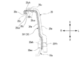
チェーンケース20について、図2を参照して詳細に説明する。
チェーンケース20は、前述のようにスイングアーム10の上側のチェーン11を覆う形状であって、チェーン11に対して車幅方向外面側を覆うケース側面壁部20wとチェーン11に対して天面側を覆うケース天面壁部20uとを有している。すなわち、チェーンケース20は、チェーン11の外側と上側との2側面のみを覆う構造となっている。また、ケース側面壁部20wは、前後方向の中段部を境にして、ケース前端20feまでの前方側の上下方向の幅が広くなっており、後方側がケース後端20reに向かって先細りになる形状となっている。そして、チェーンケース20は、ケース側面壁部20wの下端側の前部固定部20mに設けられた前部ネジ穴20fhおよび後部固定部20nに設けられた後部ネジ穴20rhを貫通させるネジ12,15にてスイングアーム10に固定されている。
The
The
本実施形態においては、図1に示すように、チェーンケース20は、側面視で車体フレーム2と重なるように設けられている。そして、チェーンケース20の車体フレーム2と重なる部分に、図2に示すように、チェーンケース20の車幅方向の幅を小さくする凹部20dが設けられている。
In the present embodiment, as shown in FIG. 1, the
また、本実施形態においては、図2に示すように、ケース側面壁部20wに、ケース側面壁部20wの肉厚方向の段差を構成する2つの段部20i,20iiが形成されている。上側の段部20iは、ケース側面壁部20wの上下方向の中段部にから上部にわたって形成されている。さらに詳細には、ケース上下方向の中段部に形成された段部20iは、ケース側面壁部20wの前部側においては略水平に形成され、段部20iの後方部分は、クッションユニット用凹部20g(リアクッション5に対応した凹み部分)に向かって上方に傾斜して延びている。また、下側の段部20iiは、ケース側面壁部20wの下端部において、ケース前端20feからケース後端20reまでの全域にわたって形成されている。このように2つの段部20i,20iiが形成されていることで、側面視で凹部20dが形成された領域において、上下に並んだ2つの段部20i,20iiが位置する構造となっている。
In the present embodiment, as shown in FIG. 2, two
本実施形態においては、チェーンケース20の内面には、図2に示すように、ケース側面壁部20wおよびケース天面壁部20uに多数の補強内リブ20vが設けられている。この補強内リブ20vは、ケース側面壁部20wからケース天面壁部20uに連続する構造とすることができる。この補強内リブ20vによって、チェーンケース20の剛性を維持しつつ薄肉・軽量化を図ることができる。
In the present embodiment, as shown in FIG. 2, a large number of reinforcing
本実施形態におけるチェーンケース20の固定は、前掲の如く前部固定部20mと後部固定部20nの二箇所にて行われるが、ケース上側を構成するケース天面壁部20uは、車幅方向内側に延出されて自由端20ueとなっている。ここで、前部固定部20mは、例えば、図1に示すように、側面視で後輪RWよりも若干前方寄りの位置に設けられた前部ブラケット10aにネジ12を介して固定される。また、後部固定部20nは、後輪RWの車軸(後端10rと同じ位置)の上側に形成された後部ブラケット10jにネジ15を介して固定される。
The
また、前部固定部20mと後部固定部20nには、それぞれ補強板30が設けられている。この2つの補強板30については、形状が若干異なった形状であり、図3に前部固定部20mに設けられる前部補強板30fを示し、図7に後部固定部20nに設けられる後部補強板30rを示す。
Reinforcing
図3および図4に示す前部補強板30fは、前掲のごとく前部固定部20mに設けられるが、ケース側面壁部20wに対面する垂直壁部30wと、ケース天面壁部20uに対面するとともに先端30eが若干下方に屈曲した水平壁部30uと、を有する構造である。そして、水平壁部30uには、前後に並んだ2個の円形の突起受容部30hが開口されている。また、垂直壁部30wの下端部30weは、車両外側(左側)に若干膨らむような段差を有し、取付け孔30whを備えている。
The front reinforcing
一方、ケース天面壁部20uの内面には、図2に示すように、位置決め用突起20uaが前後に2個並んで設けられている。また、位置決め用突起20uaよりも車両内側(右側)には、図4および図5に示すように、前掲の前部補強板30fの先端30eが貫通可能な天面開口20uhが設けられている。また、この天面開口20uhが形成された部分に略対応して車両内方へ若干突出する突出片20pが形成されている。
On the other hand, as shown in FIG. 2, two positioning projections 20ua are provided on the inner surface of the case
この前部補強板30fは、図4および図5に示すように、前方(後方にも天面開口20uhを有する)の天面開口20uhに先端30eを貫通して突出片20pに係合し、且つ突起受容部30hに位置決め用突起20uaをはめ込まれた状態でチェーンケース20の内側に装着される。ここで、前部補強板30fの先端30eは、下向きに屈曲して延出しているので、突出片20pを引っ掛けるように保持する。
この前部補強板30fの下端部30weは、スイングアーム10に取り付けられた前部ブラケット10aに取付けられる。そして、前部ブラケット10aの雌ねじ部10adにねじ込むネジ12により、前部補強板30fは前部ブラケット10aとチェーンケース20の前部固定部20mとの間に挟み込むように固定される。すなわち、ネジ12によってチェーンケース20とスイングアーム10が共締め固定される。
As shown in FIGS. 4 and 5, the
A lower end 30we of the front reinforcing
また、本実施形態におけるスイングアーム10は、前掲の如く左右一対設けられているが、前端10fの近傍において車幅方向に延出されるプレート状のクロスメンバー13(図6参照)にて連結されている。そして、このクロスメンバー13上に前部ブラケット10aが設けられている。
前部ブラケット10aは、クロスメンバー13上で車幅方向に延びる取付け基部10abが例えば溶接固定されている。また、前部ブラケット10aは、取付け基部10abの一端側が垂直に立ち上がり、且つ内側に補強リブ10avを備えると共に補強リブ10avよりも上部に雌ねじ部10adを備える取付け面部10acが設けられている。また、取付け基部10abの上には、チェーン11の走行位置に対応してチェーンスライダ14が設けられている。
The
In the
後部補強板30rは、図7に示すように、前部補強板30fと同様にケース側面壁部20wに対面する垂直壁部30wと、ケース天面壁部20uに対面する水平壁部30uを有しており、さらに水平壁部30uから下方に屈曲した下向き先端部30bを有する構造である。そして、水平壁部30uの中央領域および垂直壁部30wの上部には、外面が凹んだ凹部30udが形成されている。また、水平壁部30uには、凹部30udから外れた位置の前後に2個の円形の突起受容部30hが開口されている。また、垂直壁部30wは、前部補強板30fと同様に車両外側(左側)に膨らむような段差を有する下端部30weに取付け孔30whを備えている。
なお、凹部30udは、後部補強板30rの剛性を高めることができるだけでなく、後部補強板30rがチェーンケース20の内側に装着された際に、図2に示すように、例えば2本の補強内リブ20vを受容して、補強内リブ20vと干渉しない凹み形状としても有効である。
As shown in FIG. 7, the
The concave portion 30ud can not only increase the rigidity of the
このように構成された後部補強板30rは、図2および図5に示すように、後方の天面開口20uhに先端30eを貫通させ、且つ突起受容部30hに位置決め用突起20uaをはめ込むようにした状態でチェーンケース20の内側に装着される。そして、後部補強板30rの下端部30weが、スイングアーム10の後部ブラケット10jに取付けられる。この後部補強板30rにおいても、前部補強板30fの取付け構造と同様に、後部ブラケット10jとチェーンケース20のとの間に挟み込まれて固定されている。
As shown in FIGS. 2 and 5, the
このように本実施形態においては、チェーンケース20は、車幅方向外面側を構成するケース側面壁部20wがスイングアーム10に支持され、上面側を構成するケース天面壁部20uが車幅方向内側に延出されて自由端20ueに形成されていることで、チェーン11を覆う壁面を少なくできるので、小型かつ軽量化することができる。
さらに、本実施形態においては、チェーンケース20をそのケース内側から支持する補強板30が、ケース側面壁部20wからケース天面壁部20uに沿って延びるようにスイングアーム10に共締め固定されているので、チェーンケース20が補強されている。さらに、補強板30の固定は片持ち支持構造であるので、車両内側(タイヤ側)のコンパクト化を図ることができる。したがって、片持ちであっても車幅方向に大きなスペースをとらず、重量増加についても抑制され且つ所望の剛性を有するチェーンケース20を備えた自動二輪車1を提供することができる。
As described above, in this embodiment, the
Furthermore, in this embodiment, the reinforcing
また、本実施形態においては、ケース天面壁部20uに位置決め用突起20uaが設けられる一方、補強板30に位置決め用突起20uaに嵌る突起受容部30hが開口されていることにより、補強板30とチェーンケース20とが簡単な構造で仮止め状態にできるので、チェーンケース20の組み付け時や取り外し時等において両部材間の位置ずれの発生を防止でき、取扱い性を良くすることができる。
In the present embodiment, the positioning projection 20ua is provided on the case top
また、本実施形態におけるチェーンケース20は、側面視で車体フレーム2と重なる部分に、凹部20dが設けられているので、車体フレーム2と重なる部分が車体フレーム2から逃げるようにできる。したがって、チェーンケース20と車体フレーム2との干渉を防止できる。さらに、補強板30が凹部20dの形成された部位に重なるように設けられていることにより、チェーンケース20を車幅方向に薄く構成しつつ効率よく剛性を高めることできる。
Further, the
また、本実施形態におけるチェーンケース20のケース側面壁部20wには、ケース側面壁部20wの肉厚方向の段差を構成する段部20i,20iiが形成されているので、チェーンケース20を補強することができる。特に、チェーンケース20の凹部20dが形成された領域には、上下に2つの段部20i,20iiが重なるように設けられているので、凹部20dが形成された領域を効果的に補強することができる。
Further, the case
また、本実施形態においては、チェーンケース20の内面に、補強内リブ20vが設けられていることで、チェーンケース20全体を軽量化しつつ補強することができる。また、補強内リブ20vが、ケース側面壁部20wからケース天面壁部20uに連続する構造によって、効果的な補強ができる。
Further, in the present embodiment, since the reinforcing
また、本実施形態においては、ケース天面壁部20uには、自由端20ue近傍に天面開口20uhが設けられ、補強板30の先端30eは、天面開口20uhを貫通して下方向きに屈曲形成されていることにより、チェーンケース20の自由端20ueの近傍を補強板30にて確実に係止できる。また、天面開口20uhへ補強板30の先端30eを挿入することにより、補強板30とチェーンケース20とを位置決めできるので、組み付け時や取り外し時等において取扱い性を良くすることができる。
In the present embodiment, the case
また、本実施形態においては、左右一対のスイングアーム10を連結するクロスメンバー13上に補強板30を支持する前部ブラケット10aが設けられていることで、スイングアーム10における剛性の高いクロスメンバー13上に前部ブラケット10aを保持できる。したがって、補強板30を強固に支持でき、補強板30の支持ならびにチェーンケース20の支持剛性を高くすることができる。
In the present embodiment, the
本実施形態においては、チェーンケース20の自由端20ueが下方に向けて屈曲(図5参照)していることで、チェーンケース20の剛性をアップすることができる。
In the present embodiment, since the free end 20ue of the
以上、本発明の一実施形態について説明したが、本発明はこれに限るものではなく、適宜変更できる。例えば、上記実施形態では、補強板30が前後に2つ設けられたが、前方側の1つでも良い。また、上記実施形態においては、補強板30の突起受容部30hは、開口として形成されたが、開口ではなく凹み構造であってもよい。
また、補強板30の形状については、片持ち支持構造であれば上記実施形態に示した構造に限るものではなく、取り付け位置やチェーンケース20の形状に対応して適宜変更することができる。
また、上記実施形態においては、チェーンケース20の段部20i,20iiが複数設けられたが、1つでも又さらに多く設ける構造であっても良く、適宜変更することができる。
また、上記実施形態においては、自動二輪車について説明したが、本発明は、他の車両、例えばバギー等の鞍乗型車両でもよい。
As mentioned above, although one Embodiment of this invention was described, this invention is not restricted to this, It can change suitably. For example, in the above embodiment, two reinforcing
Further, the shape of the reinforcing
Moreover, in the said embodiment, although the
Moreover, although the motorcycle has been described in the above embodiment, the present invention may be another vehicle, for example, a straddle-type vehicle such as a buggy.
1 自動二輪車
2 車体フレーム
8 パワーユニット
10 スイングアーム
10a 前部ブラケット
10j 後部ブラケット
10f 前端
10r 後端
11 チェーン
13 クロスメンバー
20 チェーンケース
20d 凹部
20i,20ii 段部
20v 補強内リブ
20uh 天面開口
20u ケース天面壁部
20ua 位置決め用突起
20ue 自由端
20w ケース側面壁部
30 補強板
30e 補強板の先端
30h 突起受容部
30f 前部補強板
30r 後部補強板
RW 後輪
DESCRIPTION OF SYMBOLS 1
Claims (8)
パワーユニット(8)からの駆動力を前記後輪(RW)に伝達するチェーン(11)と、
少なくとも前記チェーン(11)の車幅方向外面側および上面側を覆うチェーンケース(20)と、
を備える自動二輪車(1)であって、
前記チェーンケース(20)は、前記車幅方向外面側を構成するケース側面壁部(20w)が前記スイングアーム(10)に支持され、前記上面側を構成するケース天面壁部(20u)が車幅方向内側に延出されて自由端(20ue)となっており、
前記チェーンケース(20)には、ケース内側に少なくとも1つの補強板(30)が設けられ、
前記補強板(30)は、前記ケース側面壁部(20w)から前記ケース天面壁部(20u)に沿って延び且つ前記チェーンケース(20)と共に前記スイングアーム(10)に共締め固定されている
ことを特徴とする自動二輪車(1)。 A swing arm (10) whose front end (10f) is swingably supported and whose rear end (10r) rotatably supports the rear wheel (RW);
A chain (11) for transmitting driving force from the power unit (8) to the rear wheel (RW);
A chain case (20) covering at least the outer surface side and the upper surface side in the vehicle width direction of the chain (11);
A motorcycle (1) comprising:
In the chain case (20), a case side wall portion (20w) constituting the vehicle width direction outer surface side is supported by the swing arm (10), and a case top surface wall portion (20u) constituting the upper surface side is provided in the vehicle. It extends to the inner side in the width direction and becomes a free end (20 ue),
The chain case (20) is provided with at least one reinforcing plate (30) inside the case,
The reinforcing plate (30) extends along the case top wall (20u) from the case side wall (20w) and is fastened together with the chain case (20) to the swing arm (10). Motorcycle (1) characterized by the above.
前記補強板(30)には、前記位置決め用突起(20ua)に嵌まる突起受容部(30h)が設けられている
ことを特徴とする請求項1に記載の自動二輪車(1)。 A positioning projection (20ua) is provided on the inner surface of the case top wall (20u),
The motorcycle (1) according to claim 1, wherein the reinforcing plate (30) is provided with a protrusion receiving portion (30h) that fits into the positioning protrusion (20ua).
前記チェーンケース(20)には、側面視で前記車体フレーム(2)と重なる部分に凹部(20d)が設けられ、
前記補強板(30)が、前記凹部(20d)の設けられた部位に重なるように設けられている
ことを特徴とする請求項1または2に記載の自動二輪車(1)。 The chain case (20) is provided so as to overlap the vehicle body frame (2) in a side view,
The chain case (20) is provided with a recess (20d) in a portion overlapping the body frame (2) in a side view,
The motorcycle (1) according to claim 1 or 2, wherein the reinforcing plate (30) is provided so as to overlap with a portion where the concave portion (20d) is provided.
ことを特徴とする請求項3に記載の自動二輪車(1)。 The said case side wall part (20w) is formed with the step part (20i, 20ii) which comprises the level | step difference of the thickness direction of the said case side wall part (20w). Motorcycle (1).
ことを特徴とする請求項1〜4の何れか一項に記載の自動二輪車(1)。 The motorcycle (1) according to any one of claims 1 to 4, wherein a reinforcing inner rib (20v) is provided on an inner surface of the chain case (20).
前記補強板(30)の先端(30e)は、前記天面開口(20uh)を貫通して下方向きに屈曲形成されている
ことを特徴とする請求項1〜5の何れか一項に記載の自動二輪車(1)。 The case top wall portion (20u) is provided with a top surface opening (20uh) in the vicinity of the free end (20ue),
The front end (30e) of the reinforcing plate (30) is bent downwardly through the top surface opening (20uh), according to any one of claims 1 to 5. Motorcycle (1).
前記クロスメンバー(13)上に前記補強板(30)を支持する前部ブラケット(10a)が設けられている
ことを特徴とする請求項1〜6の何れか一項に記載の自動二輪車(1)。 The pair of left and right swing arms (10) are connected by a cross member (13) extending in the vehicle width direction,
The motorcycle (1) according to any one of claims 1 to 6, wherein a front bracket (10a) for supporting the reinforcing plate (30) is provided on the cross member (13). ).
ことを特徴とする請求項1〜7の何れか一項に記載の自動二輪車(1)。 The motorcycle (1) according to any one of claims 1 to 7, wherein the free end (29ue) is bent downward.
Priority Applications (2)
| Application Number | Priority Date | Filing Date | Title |
|---|---|---|---|
| JP2015026458A JP6220801B2 (en) | 2015-02-13 | 2015-02-13 | Motorcycle |
| BR102016001892-7A BR102016001892B1 (en) | 2015-02-13 | 2016-01-28 | MOTORCYCLE |
Applications Claiming Priority (1)
| Application Number | Priority Date | Filing Date | Title |
|---|---|---|---|
| JP2015026458A JP6220801B2 (en) | 2015-02-13 | 2015-02-13 | Motorcycle |
Publications (2)
| Publication Number | Publication Date |
|---|---|
| JP2016147618A true JP2016147618A (en) | 2016-08-18 |
| JP6220801B2 JP6220801B2 (en) | 2017-10-25 |
Family
ID=56690841
Family Applications (1)
| Application Number | Title | Priority Date | Filing Date |
|---|---|---|---|
| JP2015026458A Active JP6220801B2 (en) | 2015-02-13 | 2015-02-13 | Motorcycle |
Country Status (2)
| Country | Link |
|---|---|
| JP (1) | JP6220801B2 (en) |
| BR (1) | BR102016001892B1 (en) |
Cited By (2)
| Publication number | Priority date | Publication date | Assignee | Title |
|---|---|---|---|---|
| JP2021030932A (en) * | 2019-08-27 | 2021-03-01 | 本田技研工業株式会社 | Saddle-riding type vehicle |
| DE112020006769T5 (en) | 2020-02-21 | 2022-12-15 | Honda Motor Co., Ltd. | Saddle-on type vehicle |
Citations (5)
| Publication number | Priority date | Publication date | Assignee | Title |
|---|---|---|---|---|
| JPH01123985U (en) * | 1988-02-16 | 1989-08-23 | ||
| JPH058776A (en) * | 1991-07-03 | 1993-01-19 | Honda Motor Co Ltd | Chain cover attaching structure for motorcycle |
| JPH1086869A (en) * | 1996-09-19 | 1998-04-07 | Yamaha Motor Co Ltd | License lamp mounting structure for motorcycle |
| JP2000128047A (en) * | 1998-10-26 | 2000-05-09 | Yamaha Motor Co Ltd | Motor bicycle belt cover |
| JP2012131333A (en) * | 2010-12-21 | 2012-07-12 | Honda Motor Co Ltd | Chain adjuster structure of saddle type vehicle |
-
2015
- 2015-02-13 JP JP2015026458A patent/JP6220801B2/en active Active
-
2016
- 2016-01-28 BR BR102016001892-7A patent/BR102016001892B1/en active IP Right Grant
Patent Citations (5)
| Publication number | Priority date | Publication date | Assignee | Title |
|---|---|---|---|---|
| JPH01123985U (en) * | 1988-02-16 | 1989-08-23 | ||
| JPH058776A (en) * | 1991-07-03 | 1993-01-19 | Honda Motor Co Ltd | Chain cover attaching structure for motorcycle |
| JPH1086869A (en) * | 1996-09-19 | 1998-04-07 | Yamaha Motor Co Ltd | License lamp mounting structure for motorcycle |
| JP2000128047A (en) * | 1998-10-26 | 2000-05-09 | Yamaha Motor Co Ltd | Motor bicycle belt cover |
| JP2012131333A (en) * | 2010-12-21 | 2012-07-12 | Honda Motor Co Ltd | Chain adjuster structure of saddle type vehicle |
Cited By (7)
| Publication number | Priority date | Publication date | Assignee | Title |
|---|---|---|---|---|
| JP2021030932A (en) * | 2019-08-27 | 2021-03-01 | 本田技研工業株式会社 | Saddle-riding type vehicle |
| CN112441164A (en) * | 2019-08-27 | 2021-03-05 | 本田技研工业株式会社 | Saddle-ride type vehicle |
| CN112441164B (en) * | 2019-08-27 | 2022-05-03 | 本田技研工业株式会社 | Saddle-ride type vehicle |
| US11492059B2 (en) | 2019-08-27 | 2022-11-08 | Honda Motor Co., Ltd. | Saddle riding vehicle |
| JP7234075B2 (en) | 2019-08-27 | 2023-03-07 | 本田技研工業株式会社 | saddle-riding vehicle |
| DE112020006769T5 (en) | 2020-02-21 | 2022-12-15 | Honda Motor Co., Ltd. | Saddle-on type vehicle |
| US11919593B2 (en) | 2020-02-21 | 2024-03-05 | Honda Motor Co., Ltd. | Saddle-ride type vehicle |
Also Published As
| Publication number | Publication date |
|---|---|
| BR102016001892A2 (en) | 2016-10-18 |
| BR102016001892B1 (en) | 2022-11-16 |
| JP6220801B2 (en) | 2017-10-25 |
Similar Documents
| Publication | Publication Date | Title |
|---|---|---|
| JP4815979B2 (en) | Lower body structure of automobile | |
| US10000252B2 (en) | Swingarm support structure | |
| JP2006219068A (en) | Installation structure for mounting device | |
| JP6220801B2 (en) | Motorcycle | |
| JP6337758B2 (en) | Motorcycle parts mounting structure and mounting method thereof | |
| KR101856240B1 (en) | Shock absorber housing and fixing structure thereof | |
| KR101543004B1 (en) | Mounting unit for vehicle | |
| JP5999506B2 (en) | Car body holding structure of resin front end | |
| CN108820106B (en) | Electric vehicle frame | |
| JP6327303B2 (en) | Lower body structure of the vehicle | |
| JP2007118951A (en) | Rear arm made by casting for two-wheel vehicle | |
| JP3319633B2 (en) | Scooter type motorcycle storage box | |
| JP5261298B2 (en) | Cover mounting structure for motorcycles | |
| JP2006168422A (en) | Bumper frame structure of vehicle | |
| JP6022346B2 (en) | Car suspension member reinforcement structure | |
| JP2009248939A (en) | Fuel tank mounting structure | |
| JP6140744B2 (en) | Rear structure of motorcycle | |
| JP6794733B2 (en) | Seat mounting structure | |
| JP2010089580A (en) | Motorcycle | |
| JP2009126207A (en) | Power unit supporting structure | |
| JP2017087977A (en) | Spare tire support structure | |
| JP5387050B2 (en) | Rear fender structure of motorcycle | |
| JP4461846B2 (en) | Trailing arm support device | |
| KR101553811B1 (en) | Front type lower arm device | |
| JP2013147184A (en) | Vehicle body front structure |
Legal Events
| Date | Code | Title | Description |
|---|---|---|---|
| A977 | Report on retrieval |
Free format text: JAPANESE INTERMEDIATE CODE: A971007 Effective date: 20161020 |
|
| A131 | Notification of reasons for refusal |
Free format text: JAPANESE INTERMEDIATE CODE: A131 Effective date: 20161025 |
|
| RD02 | Notification of acceptance of power of attorney |
Free format text: JAPANESE INTERMEDIATE CODE: A7422 Effective date: 20170120 |
|
| A131 | Notification of reasons for refusal |
Free format text: JAPANESE INTERMEDIATE CODE: A131 Effective date: 20170404 |
|
| A521 | Request for written amendment filed |
Free format text: JAPANESE INTERMEDIATE CODE: A523 Effective date: 20170525 |
|
| TRDD | Decision of grant or rejection written | ||
| A01 | Written decision to grant a patent or to grant a registration (utility model) |
Free format text: JAPANESE INTERMEDIATE CODE: A01 Effective date: 20170905 |
|
| A61 | First payment of annual fees (during grant procedure) |
Free format text: JAPANESE INTERMEDIATE CODE: A61 Effective date: 20171002 |
|
| R150 | Certificate of patent or registration of utility model |
Ref document number: 6220801 Country of ref document: JP Free format text: JAPANESE INTERMEDIATE CODE: R150 |