JP2016132956A - Steel pipe pile with air chamber - Google Patents
Steel pipe pile with air chamber Download PDFInfo
- Publication number
- JP2016132956A JP2016132956A JP2015009950A JP2015009950A JP2016132956A JP 2016132956 A JP2016132956 A JP 2016132956A JP 2015009950 A JP2015009950 A JP 2015009950A JP 2015009950 A JP2015009950 A JP 2015009950A JP 2016132956 A JP2016132956 A JP 2016132956A
- Authority
- JP
- Japan
- Prior art keywords
- steel pipe
- pipe pile
- air chamber
- ground
- pile
- Prior art date
- Legal status (The legal status is an assumption and is not a legal conclusion. Google has not performed a legal analysis and makes no representation as to the accuracy of the status listed.)
- Pending
Links
Images


Abstract
Description
この発明は、軟弱地盤を改良するための摩擦杭あるいは支持杭に関するものである。 The present invention relates to a friction pile or a support pile for improving soft ground.
中小規模の建築物を構築する場合、基礎形成のために地盤改良を行うことがしばしばある。その手法としては、一般的にセメントを掘削孔に注入して地中杭を構築する方法、コンクリート杭(摩擦杭を含む)や鋼管杭(羽根付きを含む)を埋設する方法などが採用されている。
そして、鋼管杭を用いる工法においては、鋼管杭に螺旋羽根を取り付けると共に鋼管の周壁に多数の孔を設け、この孔からセメントミルクなどの硬化剤を地盤に吐出できるようにしたものも提案されている。
And in the construction method using steel pipe piles, there are also proposed ones in which spiral blades are attached to the steel pipe piles and a large number of holes are provided in the peripheral wall of the steel pipe so that a hardener such as cement milk can be discharged from the holes to the ground. Yes.
杭本体が鋼管その他中空の場合は、摩擦強度を高めるために、従来から杭本体内の中空部分を利用してセメントミルクなどの硬化材を杭の周壁から地盤中に吐出することが行われているが、硬化剤を吐出させるために、硬化剤を高圧ポンプで杭内に供給する手法が提案されている(例えば特許文献2)。その手法では施工において、杭を回転させるための機構と硬化剤を圧送するための機構とを備えた専用の装置を用意する必要がある。
この発明は、専用の装置を用意することなく、簡易な装置で鋼管杭の周囲、全長に亘り硬化剤の層を形成することを課題とするものである。
When the pile body is steel pipe or other hollow, in order to increase the frictional strength, conventionally, a hard material such as cement milk has been discharged from the peripheral wall of the pile into the ground using the hollow part in the pile body. However, in order to discharge the curing agent, a method of supplying the curing agent into the pile with a high-pressure pump has been proposed (for example, Patent Document 2). In this method, it is necessary to prepare a dedicated device having a mechanism for rotating the pile and a mechanism for pumping the hardener in the construction.
This invention makes it a subject to form the layer of a hardening | curing agent over the circumference | surroundings and full length of a steel pipe pile with a simple apparatus, without preparing an apparatus for exclusive use.
この発明は、先端(施工時の下端)が次第に細く形成されて閉塞された鋼管杭の先端部に、液状硬化剤を地盤に吐出するための吐出孔を複数設け、前記鋼管杭の基端(施工時の上端)に圧縮変形可能な空気室を着脱可能に取り付け、空気室を上方から押しつぶすことにより鋼管杭に注入された液状硬化剤が前記吐出孔から地盤に吐出されるようにした空気室付き鋼管杭である。空気室を取り付けることにより、専用装置を用意することなく、モンケン等でたたくことにより鋼管杭内の硬化剤を地盤に吐出することができる。
前記鋼管杭の先端部には螺旋羽根を取り付けることが好ましく、この螺旋羽根の径は、先端から基端側に向けて次第に大きくすることが好ましい(請求項2)。また、螺旋羽根は鋼管杭に装着されるスリーブに取り付けることが好ましい。このとき、このスリーブには鋼管杭に形成された吐出孔に対応する孔を設ける(請求項3)。
The present invention provides a plurality of discharge holes for discharging the liquid hardener to the ground at the distal end portion of the steel pipe pile whose tip (lower end during construction) is gradually narrowed and closed, and the base end of the steel pipe pile ( An air chamber in which a compressible deformable air chamber is detachably attached to the upper end at the time of construction, and the liquid hardener injected into the steel pipe pile is squeezed from above by discharging the air chamber from the discharge hole to the ground. It is a steel pipe pile. By attaching the air chamber, the hardener in the steel pipe pile can be discharged to the ground by striking with a monken or the like without preparing a dedicated device.
A spiral blade is preferably attached to the distal end portion of the steel pipe pile, and the diameter of the spiral blade is preferably gradually increased from the distal end toward the proximal end side (Claim 2). Moreover, it is preferable to attach a spiral blade | wing to the sleeve with which a steel pipe pile is mounted | worn. At this time, the sleeve is provided with a hole corresponding to the discharge hole formed in the steel pipe pile.
この発明の空気室付き鋼管杭は、主としてモンケン等の打撃力を利用した杭打ち機で地盤に打ち込むものであるが、回転圧入を併用することもできる。
この発明の空気室付き鋼管杭の施工は以下の手順で行う。
杭芯合わせの後、最も基端側に設けた吐出孔が地盤に埋設されるまで、打ち込む。次いで杭内に硬化剤を注入した後、空気室の上面をモンケン等でたたく。このとき、蛇腹状の空気室は上端の開口部がモンケン等で閉鎖されて押しつぶされるので、空気室内の空気が杭内を加圧し、硬化剤の一部が吐出孔から地盤に吐出される。空気室が原状復帰するごとに空気室の上面を連続してたたくと、各回ごとに硬化剤の一部が地盤に吐出し、同時に鋼管杭は次第に地盤に埋設される。施工後空気室は取り外す。
その結果、鋼管杭が完全に埋設されたときには、鋼管杭の周囲の地盤に硬化剤が浸透することとなる。
Although the steel pipe pile with an air chamber of this invention is mainly driven into the ground by a pile driving machine using a striking force such as monken, rotary press-fitting can also be used in combination.
Construction of the steel pipe pile with an air chamber of this invention is performed in the following procedures.
After the pile alignment, drive until the discharge hole provided on the most proximal side is buried in the ground. Next, after injecting the curing agent into the pile, the upper surface of the air chamber is hit with monken or the like. At this time, the opening at the upper end of the bellows-like air chamber is closed and crushed with monken or the like, so that air in the air chamber pressurizes the inside of the pile, and a part of the curing agent is discharged from the discharge hole to the ground. When the upper surface of the air chamber is continuously hit every time the air chamber returns to its original state, a part of the curing agent is discharged to the ground each time, and at the same time, the steel pipe piles are gradually embedded in the ground. Remove the air chamber after construction.
As a result, when the steel pipe pile is completely buried, the hardener penetrates into the ground around the steel pipe pile.
上記において、きわめて軟弱な地盤であれば、螺旋羽根がなくとも鋼管杭は埋設される。埋設が困難な場合は螺旋羽根を取り付けた鋼管杭を用いると、鋼管杭は打撃力によって自動的に回転して地盤に埋設される。ここで、螺旋羽根の径を先端から基端に向けて次第に大径になるものとすると、螺旋羽根による地盤の攪拌を可及的に抑えることができると共に、固い地盤であっても、抵抗が少なく埋設することができる。
また、螺旋羽根はスリーブに取り付けてあるので、必要時応じて鋼管杭に取り付けることができ、また長さの異なる鋼管杭に対しても同じ規格の螺旋羽根を取り付けることができる。
In the above, if the ground is extremely soft, the steel pipe pile is buried even without the spiral blade. When it is difficult to embed steel pipe piles with spiral blades, the steel pipe piles are automatically rotated by the impact force and buried in the ground. Here, if the diameter of the spiral blade is gradually increased from the tip toward the base end, the stirring of the ground by the spiral blade can be suppressed as much as possible, and even if the ground is hard, the resistance is low. Can be buried less.
Moreover, since the spiral blade is attached to the sleeve, it can be attached to the steel pipe pile as necessary, and the same standard spiral blade can be attached to the steel pipe piles having different lengths.
以下この発明を実施形態に基づいて説明する。 Hereinafter, the present invention will be described based on embodiments.
鋼管杭1は、先端(以下図面に基づき「下端」という。)が円錐状をなして閉塞されている。そして、下端から約1m程度上方にかけて、硬化剤の吐出孔2が複数上下に亘り、そして円周に沿って種々の向き(例えば90度ごと)に設けてある。また、この部分には、螺旋羽根3が取り付けられた約1mの長さのスリーブ4が装着してあり、このスリーブ4は前記鋼管杭1にボルトで固定してある。
前記吐出孔2は螺旋羽根3の直下に位置するように設けてあり、前記スリーブ4には、鋼管杭1に設けられた吐出孔2の位置に対応して吐出孔5が設けてある。
前記螺旋羽根とスリーブとは鋳物で一体成形することが好ましい。この場合には、螺旋羽根を中空として、螺旋羽根に吐出口を形成することも可能である。
The
The
The spiral blade and the sleeve are preferably integrally formed by casting. In this case, it is possible to form the discharge port in the spiral blade by making the spiral blade hollow.
前記螺旋羽根3の下面には排土板6が取りつけてある、後に述べるように、鋼管杭1をモンケンでたたくことにより鋼管杭1は螺旋羽根の向きに従って回転する。この排土板6は、鋼管杭の回転に伴い周囲の土砂を排除して螺旋状の溝を形成する。この溝によって吐出孔5には土砂が吐出孔に入り込む目詰まりが防止されると共に、この溝に硬化剤が吐出される。また、排土板6は一端をスリーブ4に固着させることにより、螺旋羽根の補強ともなる。
なお、螺旋羽根3を取り付けない場合は、鋼管杭1自体に土砂が吐出孔2に入り込むことを防止するための排土板を取り付ける。
As will be described later, the
In addition, when not attaching the
前記螺旋羽根3は、前記スリーブの下端から上端まででスリーブ4を3周する程度の、比較的急角度のものとして、杭の埋設時における抵抗を減殺している。加えて、螺旋羽根3の幅は前記スリーブの下端から上端に向けて次第に幅が広くしてあり、その結果、螺旋羽根の径は下から上に向けて次第に大径になっている。下端で杭の直径の1.5〜2倍程度、上端で2.5〜3倍程度が好ましい。
The
前記鋼管杭1の寸法は、一般に直径80〜250mm、長さ3〜4メートル程度であるが、これに限定されるものではない。
The dimensions of the
前記鋼管杭1の基端(以下図面に基づき「上端」という)には空気室7が取り付けてある。
この空気室7は、上下方向に圧縮変形可能でかつ迅速に復元可能な素材(ゴム系又はプラスチック系)で蛇腹状に形成してある。空気室7の上下寸法は、直径により異なるが、100mmないし250mm程度が適当と考えられる。
An air chamber 7 is attached to the base end of the steel pipe pile 1 (hereinafter referred to as “upper end” based on the drawings).
The air chamber 7 is formed in a bellows shape with a material (rubber or plastic) that can be compressed and deformed in the vertical direction and can be quickly restored. The vertical dimension of the air chamber 7 varies depending on the diameter, but is considered to be about 100 mm to 250 mm.
前記空気室7の下端には鋼板製の下板8が取り付けてあり、この下板8の下面に形成された周壁8aが鋼管杭1の上端に嵌まり、ボルト(図示しない)で固定してある。前記下板8には、空気室6内の空気を鋼管杭1内に導く穴8bが設けてある。
前記空気室7の上端には鋼板製の上板9が取り付けてあり、空気の流入のための穴9aが設けてある。この穴9aの大きさは、モンケンの打撃により閉塞される大きさとする。
なお、鋼管杭の埋設に回転圧入法を併用する場合は、前記上板の穴9aを回転装置の回転軸に対応した形状としておく。
A
An
In addition, when using the rotary press-fitting method together for embedding the steel pipe pile, the
以下、上記実施例に示す空気室付き鋼管杭の施工について説明する。
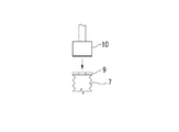
杭芯合わせの後、最も上方に設けた吐出孔2,5が地盤に埋設されるまで、鋼管杭1をモンケン10で打ち込む(図5(C))。このとき、鋼管杭1は螺旋羽根3の作用により回転しつつ埋め込まれる。鋼管杭1の回転に伴い排土板6によって地盤は抉られる。次いで杭内に硬化剤(地盤補修液)11を注入した後、空気室7の上板9をモンケン10でたたく。このとき、蛇腹状の空気室7は上板9の穴9bがモンケンで閉鎖されて押しつぶされるので、空気室7内の空気が杭内を加圧し、硬化剤の一部が吐出孔2,5から地盤に吐出される。空気室7が原状復帰するごとに空気室7の上板9を連続してたたくと、各回ごとに硬化剤の一部が地盤に吐出する。杭内の硬化剤が減少したときには補充しつつ行う。
モンケンでたたくごとに、硬化剤は吐出し、鋼管杭1は回転しつつ埋設される。その結果、鋼管杭が完全に埋設されたときには、鋼管杭の周囲の地盤に硬化剤が浸透し、ソイルセメント層などの硬化した地盤が形成される。
Hereinafter, the construction of the steel pipe pile with an air chamber shown in the above embodiment will be described.
After the pile core alignment, the
Every time the monken is struck, the curing agent is discharged, and the
硬化剤の吐出において、排土板によって地盤が抉られるので硬化剤は地盤となじみやすく、また吐出孔が目詰まりするおそれも減殺される。
鋼管杭が埋設された後、空気室7は取り外し、鋼管杭1に基礎と結合する鉄筋を挿入した上で、基礎コンクリートを打設する。コンクリートが鋼管杭1内に充填されることにより、現場打ちのコンクリート杭となるので、鋼管杭1が腐食しても杭としての機能が維持される。そのために、鋼管杭1は肉厚が薄くても、またメッキされたものであっても使用することができ、コストダウンをはかることができる。
In discharging the curing agent, since the ground is crushed by the earth discharging plate, the curing agent is easily compatible with the ground, and the possibility of clogging the discharge holes is reduced.
After the steel pipe pile is buried, the air chamber 7 is removed, and a steel bar is inserted into the
以上のように施工されたこの実施例の鋼管杭1は、その周囲に硬化剤の層(例えばソイルセメント層)が形成されるので摩擦力が高く、加えて螺旋羽根がソイルセメント層で固められるので引き抜き強度の向上、沈下の防止に寄与する。また、杭内の硬化剤は空気圧によって吐出されるので、硬化剤の杭内への残留も可及的に減少させることができる。
The
この発明の空気室付き鋼管杭によれば、簡易な装置で引き抜き強度の高い補強杭を施工することができる。 According to the steel pipe pile with an air chamber of the present invention, it is possible to construct a reinforcing pile having high pulling strength with a simple device.
1 鋼管杭
2 吐出孔
3 螺旋羽根
4 スリーブ
5 吐出孔
6 排土板
7 空気室
8 下板
9 上板
10 モンケン
DESCRIPTION OF
Claims (3)
3. The steel pipe pile with an air chamber according to claim 2, wherein the spiral blade is attached to a sleeve attached to the steel pipe pile, and the sleeve is provided with a hole corresponding to a discharge hole formed in the steel pipe pile.
Priority Applications (1)
| Application Number | Priority Date | Filing Date | Title |
|---|---|---|---|
| JP2015009950A JP2016132956A (en) | 2015-01-22 | 2015-01-22 | Steel pipe pile with air chamber |
Applications Claiming Priority (1)
| Application Number | Priority Date | Filing Date | Title |
|---|---|---|---|
| JP2015009950A JP2016132956A (en) | 2015-01-22 | 2015-01-22 | Steel pipe pile with air chamber |
Publications (1)
| Publication Number | Publication Date |
|---|---|
| JP2016132956A true JP2016132956A (en) | 2016-07-25 |
Family
ID=56437440
Family Applications (1)
| Application Number | Title | Priority Date | Filing Date |
|---|---|---|---|
| JP2015009950A Pending JP2016132956A (en) | 2015-01-22 | 2015-01-22 | Steel pipe pile with air chamber |
Country Status (1)
| Country | Link |
|---|---|
| JP (1) | JP2016132956A (en) |
-
2015
- 2015-01-22 JP JP2015009950A patent/JP2016132956A/en active Pending
Similar Documents
| Publication | Publication Date | Title |
|---|---|---|
| JP2008175039A (en) | Method of driving both steel pipe pile and soil cement pile | |
| JP5658988B2 (en) | Soil cement steel pipe composite pile and its construction method | |
| KR101147510B1 (en) | Complex pile with improved end bearing capacity and piling method of complex pile using the same | |
| JP4716134B2 (en) | Slope stabilization method | |
| JP4693423B2 (en) | Pile head reinforcement method | |
| JP5936996B2 (en) | Rooting construction method of rotary intrusion pile | |
| JP5546000B2 (en) | Ground excavation method | |
| JP5177066B2 (en) | Steel pipe pile and its construction method | |
| JP2016132956A (en) | Steel pipe pile with air chamber | |
| JP5852776B2 (en) | Ground excavation method and excavator | |
| KR101438013B1 (en) | Complex pile with improved end bearing capacity and its construction method | |
| JP5698316B2 (en) | Construction method of foundation pile | |
| JP5545999B2 (en) | Ground excavation method | |
| KR102070490B1 (en) | Pile removal apparatus | |
| JP2010144347A (en) | Soil improving apparatus and soil improving method | |
| JP2008255695A (en) | Method of constructing steel pipe pile | |
| JP6396226B2 (en) | Micropile method | |
| JP6074472B2 (en) | Ground excavation method and excavator | |
| JP4501249B2 (en) | Steel pipe pile and its construction method | |
| JP6634251B2 (en) | Pile foundation structure, ready-made pile burying device, method of constructing pile foundation structure using said ready-made pile burying device | |
| JP4615841B2 (en) | Synthetic pile construction method and synthetic pile | |
| JP2010248841A (en) | Underground anchor | |
| JP6216526B2 (en) | Steel pipe head attachment | |
| KR102270555B1 (en) | Method for reinforcing ground using grouting bead and helical pile | |
| KR101166873B1 (en) | Earth drilling method for preventing soil from emitting by casing and earth reinforcement method thereof |