JP2016129968A - Sheet production apparatus and sheet production method - Google Patents
Sheet production apparatus and sheet production method Download PDFInfo
- Publication number
- JP2016129968A JP2016129968A JP2015004835A JP2015004835A JP2016129968A JP 2016129968 A JP2016129968 A JP 2016129968A JP 2015004835 A JP2015004835 A JP 2015004835A JP 2015004835 A JP2015004835 A JP 2015004835A JP 2016129968 A JP2016129968 A JP 2016129968A
- Authority
- JP
- Japan
- Prior art keywords
- unit
- defibrated material
- web
- manufacturing apparatus
- sheet manufacturing
- Prior art date
- Legal status (The legal status is an assumption and is not a legal conclusion. Google has not performed a legal analysis and makes no representation as to the accuracy of the status listed.)
- Granted
Links
Images


Classifications
-
- Y—GENERAL TAGGING OF NEW TECHNOLOGICAL DEVELOPMENTS; GENERAL TAGGING OF CROSS-SECTIONAL TECHNOLOGIES SPANNING OVER SEVERAL SECTIONS OF THE IPC; TECHNICAL SUBJECTS COVERED BY FORMER USPC CROSS-REFERENCE ART COLLECTIONS [XRACs] AND DIGESTS
- Y02—TECHNOLOGIES OR APPLICATIONS FOR MITIGATION OR ADAPTATION AGAINST CLIMATE CHANGE
- Y02W—CLIMATE CHANGE MITIGATION TECHNOLOGIES RELATED TO WASTEWATER TREATMENT OR WASTE MANAGEMENT
- Y02W30/00—Technologies for solid waste management
- Y02W30/50—Reuse, recycling or recovery technologies
- Y02W30/64—Paper recycling
Abstract
Description
本発明は、シート製造装置およびシート製造方法に関する。 The present invention relates to a sheet manufacturing apparatus and a sheet manufacturing method.
従来、シート製造装置においては、繊維を含む原料を水に投入し、主に機械的作用により離解して、抄き直す、いわゆる湿式方式が採用されている。このような湿式方式のシート製造装置は、大量の水が必要であり、装置が大きくなる。さらに、水処理施設の整備のメンテナンスに手間がかかる上、乾燥工程に係るエネルギーが大きくなる。 2. Description of the Related Art Conventionally, in a sheet manufacturing apparatus, a so-called wet method is adopted in which a raw material containing fibers is put into water, disaggregated mainly by a mechanical action, and re-made. Such a wet type sheet manufacturing apparatus requires a large amount of water, and the apparatus becomes large. Furthermore, it takes time and effort to maintain the water treatment facility, and energy related to the drying process increases.
そこで、小型化、省エネルギーのために、水を極力利用しない乾式によるシート製造装置が提案されている。例えば特許文献1には、乾式解繊機において紙片を繊維状に解繊し、サイクロンにおいて繊維の脱墨を行い、脱墨された繊維を、フォーミングドラム表面の小孔スクリーンを通過させて、メッシュベルト上に堆積させ、紙を成形することが記載されている。 Therefore, for the purpose of miniaturization and energy saving, a dry sheet manufacturing apparatus that uses water as little as possible has been proposed. For example, in Patent Document 1, a piece of paper is fibrillated in a dry defibrating machine, the fiber is deinked in a cyclone, and the deinked fiber is passed through a small hole screen on the surface of the forming drum to obtain a mesh belt. It is described to deposit on top and form a paper.
上記のようなシート製造装置では、例えば、繊維状に解繊された解繊物を結着させるために、樹脂を含む添加物を添加する。しかしながら、シート製造装置中を流れる解繊物の量(解繊物の流量)は、特にシート製造装置の起動時や原料の残量が少なくなったときなどに、ばらつく傾向にある。そのため、解繊物の量に対する添加物の量が変動し、所望の質感や強度を有するシートを製造することができない場合がある。 In the sheet manufacturing apparatus as described above, for example, an additive containing a resin is added to bind a defibrated material that has been fibrillated. However, the amount of defibrated material flowing through the sheet manufacturing apparatus (flow rate of the defibrated material) tends to vary, particularly when the sheet manufacturing apparatus is started up or when the remaining amount of raw material is low. Therefore, the amount of the additive with respect to the amount of defibrated material may vary, and a sheet having a desired texture and strength may not be manufactured.
このように、従来のシート製造装置では、シート製造装置中を流れる解繊物の流量の変動を把握することができず、特性の安定したシートを製造することが困難であった。 As described above, the conventional sheet manufacturing apparatus cannot grasp the fluctuation of the flow rate of the defibrated material flowing in the sheet manufacturing apparatus, and it is difficult to manufacture a sheet having stable characteristics.
本発明のいくつかの態様に係る目的の1つは、シート製造装置中を流れる解繊物の流量の変動を把握することができるシート製造装置を提供することにある。また、本発明のいくつかの態様に係る目的の1つは、シート製造装置中を流れる解繊物の流量の変動を把握することができるシート製造方法を提供することにある。 One of the objects according to some aspects of the present invention is to provide a sheet manufacturing apparatus capable of grasping fluctuations in the flow rate of the defibrated material flowing in the sheet manufacturing apparatus. Moreover, one of the objects according to some aspects of the present invention is to provide a sheet manufacturing method capable of grasping fluctuations in the flow rate of the defibrated material flowing in the sheet manufacturing apparatus.
本発明は前述の課題の少なくとも一部を解決するためになされたものであり、以下の態様又は適用例として実現することができる。 SUMMARY An advantage of some aspects of the invention is to solve at least a part of the problems described above, and the invention can be implemented as the following aspects or application examples.
本発明に係るシート製造装置の一態様は、
繊維を含む原料を解繊物に解繊する解繊部と、
前記解繊部により解繊された前記解繊物を選別する選別部と、
前記解繊物が堆積したウェブを形成するウェブ形成部と、
前記ウェブの厚さを検出する検出部と、
ほぐされた前記ウェブを堆積させる堆積部と、
を有する。
One aspect of the sheet manufacturing apparatus according to the present invention is:
A defibrating unit for defibrating raw materials containing fibers into defibrated material;
A sorting unit for sorting the defibrated material defibrated by the defibrating unit;
A web forming section for forming a web on which the defibrated material is deposited;
A detection unit for detecting the thickness of the web;
A depositing section for depositing the unraveled web;
Have
このようなシート製造装置では、厚さ検出部によって、シート製造装置中を流れる解繊物の流量の変動を把握することができる。 In such a sheet manufacturing apparatus, fluctuations in the flow rate of the defibrated material flowing in the sheet manufacturing apparatus can be grasped by the thickness detection unit.
本発明に係るシート製造装置において、
前記選別部は、
前記解繊物を選別するための複数の開口を有するドラム部と、
前記ドラム部を覆うハウジング部と、
を含み、
前記ウェブ形成部は、
前記選別部よりも重力方向下方に位置し、前記選別部により選別された前記解繊物が堆積されるメッシュベルトと、
前記メッシュベルトの重力方向下方から前記ハウジング部内の空気を吸引する吸引部と、
を含んでもよい。
In the sheet manufacturing apparatus according to the present invention,
The sorting unit
A drum portion having a plurality of openings for sorting the defibrated material;
A housing portion covering the drum portion;
Including
The web forming unit is
A mesh belt that is positioned below the sorting unit in the direction of gravity and on which the defibrated material sorted by the sorting unit is deposited;
A suction part for sucking air in the housing part from below in the gravitational direction of the mesh belt;
May be included.
このようなシート製造装置では、吸引部の吸引により、メッシュベルト上に均一性よく解繊物を堆積させることができる。したがって、このようなシート製造装置では、厚さ検出部によって、ウェブの厚さをより正確に検出することができる。 In such a sheet manufacturing apparatus, the defibrated material can be deposited on the mesh belt with good uniformity by suction of the suction part. Therefore, in such a sheet manufacturing apparatus, the thickness of the web can be detected more accurately by the thickness detection unit.
本発明に係るシート製造装置において、
前記検出部により検出された厚さに基づいて前記解繊物の流量を導出する導出部を有してもよい。
In the sheet manufacturing apparatus according to the present invention,
You may have the derivation | leading-out part which derives | leads-out the flow volume of the said defibrated material based on the thickness detected by the said detection part.
このようなシート製造装置では、検出部により検出されたウェブの厚さから、ウェブ形成部よりも下流を流れる解繊物の流量を求めることができる。 In such a sheet manufacturing apparatus, the flow rate of the defibrated material flowing downstream from the web forming unit can be obtained from the web thickness detected by the detecting unit.
本発明に係るシート製造装置において、
前記ウェブをほぐして前記堆積部に移送する管と、
前記管に添加物を供給する供給部と、
前記導出部により導出された前記解繊物の流量に基づいて、前記供給部により供給される添加物の量を制御する制御部と、
を有してもよい。
In the sheet manufacturing apparatus according to the present invention,
A tube for loosening the web and transferring it to the depositing section;
A supply for supplying additive to the tube;
Based on the flow rate of the defibrated material derived by the derivation unit, a control unit that controls the amount of additive supplied by the supply unit;
You may have.
このようなシート製造装置では、導出部において求めた解繊物の流量と、連結部に供給される添加物の量と、の比を所望の値になるように制御することにより、解繊物の量に対する、連結部に供給される添加物の量の変動を小さくすることができる。これにより、このようなシート製造装置では、解繊物の量に対する添加物の量が変動することを抑制することができ、所望の質感や強度を有するシートを製造することができる。 In such a sheet manufacturing apparatus, the defibrated material is controlled by controlling the ratio of the flow rate of the defibrated material obtained in the derivation unit and the amount of additive supplied to the connecting unit to a desired value. The variation in the amount of additive supplied to the connecting portion with respect to the amount of can be reduced. Thereby, in such a sheet manufacturing apparatus, it can suppress that the quantity of the additive with respect to the quantity of defibrated material fluctuates, and can manufacture the sheet | seat which has desired texture and intensity | strength.
本発明に係るシート製造装置において、
前記シート製造装置内の温度を検出する温度検出部を有し、
前記導出部は、前記温度検出部により検出された温度に基づいて、前記解繊物の流量を導出してもよい。
In the sheet manufacturing apparatus according to the present invention,
A temperature detection unit for detecting the temperature in the sheet manufacturing apparatus;
The derivation unit may derive the flow rate of the defibrated material based on the temperature detected by the temperature detection unit.
このようなシート製造装置では、シート製造装置内の温度を考慮して、解繊物の流量を、より正確に導出することができる。 In such a sheet manufacturing apparatus, the flow rate of the defibrated material can be derived more accurately in consideration of the temperature in the sheet manufacturing apparatus.
本発明に係るシート製造装置において、
前記シート製造装置内の湿度を検出する湿度検出部を有し、
前記導出部は、前記湿度検出部により検出された湿度に基づいて、前記解繊物の流量を導出してもよい。
In the sheet manufacturing apparatus according to the present invention,
A humidity detecting unit for detecting humidity in the sheet manufacturing apparatus;
The derivation unit may derive the flow rate of the defibrated material based on the humidity detected by the humidity detection unit.
このようなシート製造装置では、シート製造装置内の湿度を考慮して、解繊物の流量を、より正確に導出することができる。 In such a sheet manufacturing apparatus, the flow rate of the defibrated material can be derived more accurately in consideration of the humidity in the sheet manufacturing apparatus.
本発明に係るシート製造方法の一態様は、
繊維を含む原料を解繊物に解繊する工程と、
解繊された前記解繊物を選別する工程と、
選別された前記解繊物を堆積してウェブを形成する工程と、
前記ウェブの厚さを検出する工程と、
ほぐされた前記ウェブを堆積させる工程と、
を有する。
One aspect of the sheet manufacturing method according to the present invention is:
A step of defibrating a raw material containing fibers into a defibrated material;
Selecting the defibrated material that has been defibrated;
Depositing the defibrated material selected to form a web;
Detecting the thickness of the web;
Depositing the loosened web;
Have
このようなシート製造方法では、シート製造装置中を流れる解繊物の流量の変動を把握することができる。 In such a sheet manufacturing method, fluctuations in the flow rate of the defibrated material flowing in the sheet manufacturing apparatus can be grasped.
以下、本発明の好適な実施形態について、図面を用いて詳細に説明する。なお、以下に説明する実施形態は、特許請求の範囲に記載された本発明の内容を不当に限定するものではない。また、以下で説明される構成の全てが本発明の必須構成要件であるとは限らない。 DESCRIPTION OF EMBODIMENTS Hereinafter, preferred embodiments of the present invention will be described in detail with reference to the drawings. The embodiments described below do not unduly limit the contents of the present invention described in the claims. In addition, not all of the configurations described below are essential constituent requirements of the present invention.
1. シート製造装置
1.1. 構成
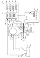
まず、本実施形態に係るシート製造装置について、図面を参照しながら説明する。図1は、本実施形態に係るシート製造装置100を模式的に示す図である。
1. Sheet manufacturing apparatus 1.1. Configuration First, a sheet manufacturing apparatus according to the present embodiment will be described with reference to the drawings. FIG. 1 is a diagram schematically illustrating a
シート製造装置100は、図1に示すように、供給部10と、製造部102と、制御部140と、を備える。製造部102は、シートを製造する。製造部102は、粗砕部12と、解繊部20と、分級部30と、選別部40と、第1ウェブ形成部45と、混合部50と、堆積部60と、第2ウェブ形成部70と、シート形成部80と、切断部90と、検出部130,132,134(図1では省略、後述する図2参照)と、を有している。
As shown in FIG. 1, the
供給部10は、粗砕部12に原料を供給する。供給部10は、例えば、粗砕部12に原料を連続的に投入するための自動投入部である。供給部10によって供給される原料は、例えば、古紙やパルプシートなどの繊維を含むものである。
The
粗砕部12は、供給部10によって供給された原料を、空気中で裁断して細片にする。細片の形状や大きさは、例えば、数cm角の細片である。図示の例では、粗砕部12は、粗砕刃14を有し、粗砕刃14によって、投入された原料を裁断することができる。粗砕部12としては、例えば、シュレッダーを用いる。粗砕部12によって裁断された原料は、ホッパー1で受けてから管2を介して、解繊部20に移送(搬送)される。
The crushing
解繊部20は、粗砕部12によって裁断された原料を解繊物に解繊する。ここで、「解繊する」とは、複数の繊維が結着されてなる原料(被解繊物)を、繊維1本1本に解きほぐすことをいう。解繊部20は、原料に付着した樹脂粒やインク、トナー、にじみ防止剤等の物質を、繊維から分離させる機能をも有する。
The
解繊部20を通過したものを「解繊物」という。「解繊物」には、解きほぐされた解繊物繊維の他に、繊維を解きほぐす際に繊維から分離した樹脂(複数の繊維同士を結着させるための樹脂)粒や、インク、トナーなどの色剤や、にじみ防止材、紙力増強剤等の添加剤を含んでいる場合もある。解きほぐされた解繊物の形状は、ひも(string)状や平ひも(ribbon)状である。解きほぐされた解繊物は、他の解きほぐされた繊維と絡み合っていない状態(独立した状態)で存在してもよいし、他の解きほぐされた解繊物と絡み合って塊状となった状態(いわゆる「ダマ」を形成している状態)で存在してもよい。
What has passed through the
解繊部20は、大気中(空気中)において乾式で解繊を行う。具体的には、解繊部20としては、インペラーミルを用いる。解繊部20は、原料を吸引し、解繊物を排出するような気流を発生させる機能を有している。これにより、解繊部20は、自ら発生する気流によって、導入口22から、原料を気流と共に吸引し、解繊処理して、排出口24へと搬送することができる。解繊部20を通過した解繊物は、管3を介して、分級部30に移送される。
The
分級部30は、解繊部20を通過した解繊物を分級する。具体的には、分級部30は、解繊物の中で比較的小さいものや密度の低いもの(樹脂粒や色剤や添加剤など)を分離して除去する。これにより、解繊物の中で比較的大きいもしくは密度の高いものである繊維の占める割合を高めることができる。
The classifying
分級部30としては、気流式分級機を用いる。気流式分級機は、旋回気流を発生させ、分級されるもののサイズと密度とにより受ける遠心力の差によって分離するものであり、気流の速度および遠心力の調整によって、分級点を調整することができる。具体的には、分級部30としては、サイクロン、エルボージェット、エディクラシファイヤーなどを用いる。特に図示のようなサイクロンは、構造が簡便であるため、分級部30として好適に用いることができる。
As the
分級部30は、例えば、導入口31と、導入口31が接続された円筒部32と、円筒部32の下方に位置し円筒部32と連続している逆円錐部33と、逆円錐部33の下部中央に設けられている下部排出口34と、円筒部32上部中央に設けられている上部排出口35と、を有している。
The
分級部30において、導入口31から導入された解繊物をのせた気流は、円筒部32で円周運動に変わる。これにより、導入された解繊物には遠心力がかかり、分級部30は、解繊物のうちで樹脂粒やインク粒よりも大きく密度の高い繊維(第1分級物)と、解繊物のうちで繊維よりも小さく密度の低い樹脂粒や色剤や添加剤など(第2分級物)と、に分離することができる。第1分級物は、下部排出口34から排出され、管4を介して、選別部40に導入される。一方、第2分級物は、上部排出口35から管5を介して受け部36に排出される。
In the
選別部40は、分級部30を通過した第1分級物(解繊部20により解繊された解繊物)を導入口42から導入し、繊維の長さによって選別する。選別部40としては、例えば、篩(ふるい)を用いる。選別部40は、網(フィルター、スクリーン)を有し、第1分級物に含まれる、網の目開きの大きさより小さい繊維または粒子(網を通過するもの、第1選別物)と、網の目開きの大きさより大きい繊維や未解繊片やダマ(網を通過しないもの、第2選別物)と、を分けることができる。例えば、第1選別物は、ホッパー6で受けてから管7を介して、混合部50に移送される。第2選別物は、排出口44から管8を介して、解繊部20に戻される。具体的には、選別部40は、モーターによって回転することができる円筒の篩である。選別部40の網は、例えば、金網、切れ目が入った金属板を引き延ばしたエキスパンドメタル、金属板にプレス機等で穴を形成したパンチングメタルを用いる。
The sorting
第1ウェブ形成部45は、選別部40を通過した第1選別物を、混合部50に搬送する。便宜上、図1では、第1ウェブ形成部45を簡略化して図示している。第1ウェブ形成部45の詳細な構造等は、後述する。
The first
混合部50は、選別部40を通過した第1選別物(第1ウェブ形成部45により搬送された第1選別物)と、樹脂を含む添加物と、を混合する。混合部50は、添加物を供給する添加物供給部52と、選別物と添加物とを搬送する管54と、ブロアー56と、を有している。図示の例では、添加物は、添加物供給部52からホッパー9を介して管54に供給される。管54は、管7と連続している。
The mixing
混合部50では、ブロアー56によって気流を発生させ、管54中において、第1選別物と添加物とを混合させながら、搬送することができる。なお、第1選別物と添加物とを混合させる機構は、特に限定されず、高速回転する羽根により攪拌するものであってもよいし、V型ミキサーのように容器の回転を利用するものであってもよい。
In the mixing
添加物供給部52としては、図1に示すようなスクリューフィーダーや、図示せぬディスクフィーダーなどを用いる。添加物供給部52から供給される添加物は、複数の繊維を結着させるための樹脂を含む。樹脂が供給された時点では、複数の繊維は結着されていない。樹脂は、シート形成部80を通過する際に溶融して、複数の繊維を結着させる。
As the
添加物供給部52から供給される樹脂は、熱可塑性樹脂や熱硬化性樹脂であり、例えば、AS樹脂、ABS樹脂、ポリプロピレン、ポリエチレン、ポリ塩化ビニル、ポリスチレン、アクリル樹脂、ポリエステル樹脂、ポリエチレンテレフタレート、ポリフェニレンエーテル、ポリブチレンテレフタレート、ナイロン、ポリアミド、ポリカーボネート、ポリアセタール、ポリフェニレンサルファイド、ポリエーテルエーテルケトン、などである。これらの樹脂は、単独または適宜混合して用いてもよい。添加物供給部52から供給される添加物は、繊維状であってもよく、粉末状であってもよい。
The resin supplied from the
なお、添加物供給部52から供給される添加物には、繊維を結着させる樹脂の他、製造されるシートの種類に応じて、繊維を着色するための着色剤や、繊維の凝集を防止するための凝集防止材、繊維等が燃えにくくするための難燃剤が含まれていてもよい。混合部50を通過した混合物(第1分級物と添加物との混合物)は、管54を介して、堆積部60に移送される。
In addition to the resin that binds the fibers, the additive supplied from the
堆積部60は、混合部50を通過した混合物を導入口62から導入し、絡み合った解繊物(繊維)をほぐして、空気中で分散させながら降らせる。さらに、堆積部60は、添加物供給部52から供給される添加物の樹脂が繊維状である場合、絡み合った樹脂をほぐす。これにより、堆積部60は、第2ウェブ形成部70に、混合物を均一性よく堆積させることができる。
The depositing
堆積部60としては、回転する円筒の篩を用いる。堆積部60は、網を有し、混合部50を通過した混合物に含まれる、網の目開きの大きさより小さい繊維または粒子(網を通過するもの)を降らせる。堆積部60の構成は、例えば、選別部40の構成と同じである。
As the
なお、堆積部60の「篩」は、特定の対象物を選別する機能を有していなくてもよい。すなわち、堆積部60として用いられる「篩」とは、網を備えたもの、という意味であり、堆積部60は、堆積部60に導入された混合物の全てを降らしてもよい。
It should be noted that the “sieving” of the depositing
第2ウェブ形成部70は、堆積部60を通過した通過物を堆積して、ウェブWを形成する。第2ウェブ形成部70は、例えば、メッシュベルト72と、張架ローラー74と、サクション機構76と、を有している。
The second web forming unit 70 deposits the passing material that has passed through the
メッシュベルト72は、移動しながら、堆積部60の開口(網の開口)を通過した通過物を堆積する。メッシュベルト72は、張架ローラー74によって張架され、通過物を通しにくく空気を通す構成となっている。メッシュベルト72は、張架ローラー74が自転することによって移動する。メッシュベルト72が連続的に移動しながら、堆積部60を通過した通過物が連続的に降り積もることにより、メッシュベルト72上にウェブWが形成される。メッシュベルト72は、例えば、金属製、樹脂製、布製、あるいは不織布等である。
While moving, the
サクション機構76は、メッシュベルト72の下方(堆積部60側とは反対側)に設けられている。サクション機構76は、下方に向く気流(堆積部60からメッシュベルト72に向く気流)を発生させることができる。サクション機構76によって、堆積部60により空気中に分散された混合物をメッシュベルト72上に吸引することができる。これにより、堆積部60からの排出速度を大きくすることができる。さらに、サクション機構76によって、混合物の落下経路にダウンフローを形成することができ、落下中に解繊物や添加物が絡み合うことを防ぐことができる。
The
以上のように、堆積部60および第2ウェブ形成部70(ウェブ形成工程)を経ることにより、空気を多く含み柔らかくふくらんだ状態のウェブWが形成される。メッシュベルト72に堆積されたウェブWは、シート形成部80へと搬送される。
As described above, the web W in a state where it contains a lot of air and is softly swollen is formed by passing through the
なお、図示の例では、ウェブWを調湿する調湿部78が設けられている。調湿部78は、ウェブWに対して水や水蒸気を添加して、ウェブWと水との量比を調節することができる。
In the illustrated example, a
シート形成部80は、メッシュベルト72に堆積したウェブWを加圧加熱してシートSを成形する。シート形成部80では、ウェブWにおいて混ぜ合された解繊物および添加物の混合物に、熱を加えることにより、混合物中の複数の繊維を、互いに添加物(樹脂)を介して結着することができる。
The
シート形成部80としては、例えば、加熱ローラー(ヒーターローラー)、熱プレス成形機、ホットプレート、温風ブロワー、赤外線加熱器、フラッシュ定着器を用いる。図示の例では、シート形成部80は、第1結着部82と第2結着部84とを備え、結着部82,84がそれぞれ一対の加熱ローラー86を備えている。結着部82,84を加熱ローラー86として構成したことにより、結着部82,84を板状のプレス装置(平板プレス装置)として構成した場合に比べて、ウェブWを連続的に搬送しながらシートSを成形することができる。なお、加熱ローラー86の数は、特に限定されない。
As the
切断部90は、シート形成部80によって成形されたシートSを切断する。図示の例では、切断部90は、シートSの搬送方向と交差する方向にシートSを切断する第1切断部92と、搬送方向に平行な方向にシートSを切断する第2切断部94と、を有している。第2切断部94は、例えば、第1切断部92を通過したシートSを切断する。
The cutting
以上により、所定のサイズの単票のシートSが成形される。切断された単票のシートSは、排出部96へと排出される。
Thus, a single-sheet sheet S having a predetermined size is formed. The cut sheet S is discharged to the
1.2. 第1ウェブ形成部
図2は、第1ウェブ形成部45を模式的に示す図である。なお、便宜上、図2では、解繊部20、選別部40、混合部50、検出部130,132,134についても模式的に示し、さらに、制御部140の機能ブロック図も示している。
1.2. First Web Forming Unit FIG. 2 is a diagram schematically showing the first
第1ウェブ形成部45は、図2に示すように、メッシュベルト120と、張架ローラー122と、吸引部(サクション機構)124と、を含む。
As shown in FIG. 2, the first
メッシュベルト120は、選別部40よりも重力方向下方(例えば物が落ちる方向)に位置している。メッシュベルト120には、選別部40により選別された解繊物が堆積される。具体的には、メッシュベルト120には、選別部40のドラム部40aに設けられた開口(網の開口)を通過した解繊物が堆積される。メッシュベルト120は、張架ローラー122によって張架され、解繊物を通しにくく空気を通す構成となっている。メッシュベルト120は、張架ローラー122が自転することによって移動する。メッシュベルト120が連続的に移動しながら、メッシュベルト120に、選別部40により選別された解繊物が連続的に降り積もることにより、メッシュベルト120上にウェブVが形成される。すなわち、第1ウェブ形成部45は、解繊物が堆積したウェブVを形成する。ウェブVは、例えば、一定の幅を有して、メッシュベルト120の移動に伴って矢印αの方向に搬送される。メッシュベルト120は、例えば、一定の速度で移動する。メッシュベルト120は、例えば、金属製、樹脂製、布製、あるいは不織布等である。
The
なお、「ウェブ」とは、複数の繊維(解繊物)が連続的につながって所定の形状をなすものであり、単票に切断される前の状態のものである。 The “web” is a state in which a plurality of fibers (defibrated material) are continuously connected to form a predetermined shape, and is in a state before being cut into single sheets.
吸引部124は、メッシュベルト120の重力方向下方に位置している。吸引部124は、メッシュベルト120の重力方向下方から選別部40のハウジング部40b内の空気を吸引し、下方に向く気流(ドラム部40aからメッシュベルト120に向く気流)を発生させることができる。吸引部124によって、ドラム部40aによりハウジング部40b内に分散された解繊物を、メッシュベルト120上に吸引することができる。これにより、ドラム部40aからの解繊物の排出速度を大きくすることができる。さらに、吸引部124によって、解繊物の落下経路にダウンフローを形成することができ、落下中に解繊物が絡み合うことを防ぐことができる。図示の例では、吸引部124は、管126を介してブロアー128に接続されている。ブロアー128を駆動させることによって、吸引部124は、ハウジング部40b内の空気を吸引することができる。
The
以上のように、選別部40および第1ウェブ形成部45(ウェブ形成工程)を経ることにより、空気を多く含み柔らかくふくらんだ状態のウェブVが形成される。ウェブVは、ホッパー129で受けてから管7を介して、混合部50に移送(搬送)される。ウェブVは、管7や管54内を移動している間にほぐされ、ほぐされた状態で堆積部60(図1参照)に移送される。すなわち、管7,54は、ウェブをほぐして堆積部60に移送するための管である。堆積部60は、ほぐされたウェブVを堆積させる。
As described above, by passing through the sorting
なお、「ほぐされたウェブ」とは、ウェブを構成する解繊物が他の解繊物と絡み合っていない状態(独立した状態)で存在してもよいし、他の解繊物と絡み合って塊状となった状態(いわゆる「ダマ」を形成している状態)で存在してもよい。 In addition, the “unraveled web” may exist in a state where the defibrated material constituting the web is not intertwined with other defibrated materials (independent state), or intertwined with other defibrated materials. It may exist in a state of being agglomerated (a state in which a so-called “dama” is formed).
混合部50の添加物供給部52は、例えば、第1ウェブ形成部45と堆積部60とを連結する連結部(図1の例では、管7,54によって構成される連結部)に添加物を供給する。具体的には、添加物供給部52は、管54に添加物を供給する。そして、管54内において、添加物と解繊物(ほぐされたウェブV)とは混合される。
The
なお、図2に示す例では、選別部40は、分級部30を通過した解繊物を選別するための複数の開口を有するドラム部40aと、ドラム部40aを覆うハウジング部40bと、を含んでいる。ドラム部40aは、例えば、円筒の篩である。ハウジング部40bは、例えば、ドラム部40aの周囲を覆う箱である。ハウジング部40bは、ホッパー6を有し、ホッパー6の開口部6aは、ドラム部40aの下方に位置している。選別部40により選別された解繊物は、開口部6aを通過して、メッシュベルト120上に堆積される。
In the example shown in FIG. 2, the sorting
また、図示の例では、ハウジング部40bは、パイルシール40cを有している。パイルシール40cは、例えば、ベース部の表面に密に細毛が植えつけられたブラシ(刷毛)で構成されおり、ブラシはメッシュベルト120と接している。パイルシール40cは、選別部40により選別された解繊物が、ハウジング部40bとメッシュベルト120との隙間から漏出することを抑制することができる。
In the illustrated example, the
1.3. 検出部
厚さ検出部130は、図2に示すように、メッシュベルト120の近傍であって、ウェブVの上方に設けられている。厚さ検出部130は、図示せぬ支持部を介して、開口部6aの外壁に固定されていてもよい。厚さ検出部130は、ウェブVの厚さを検出することができる。厚さ検出部130は、ウェブVの厚さを検出することができれば、その形態は特に限定されないが、例えば厚さ検出部130は、レーザー光をウェブVに照射して、厚さ検出部130とウェブVの表面との間の距離を検出するセンサーである。図示の例では、厚さ検出部130は、1つ設けられているが、その数は特に限定されない。例えば図示はしないが、厚さ検出部130は、3つ設けられ、ウェブVの幅方向(搬送方向αに交差する方向)において、中央部の上方と、中央部の両側に位置する外側部の上方と、に設けられていてもよい。これにより、ウェブVの厚さを、より正確に検出することができる。
1.3. As shown in FIG. 2, the
温度検出部132は、ハウジング部40bの外壁に設けられている。図示の例では、温度検出部132は、ハウジング部40bのホッパー6の外壁に設けられている。温度検出部132は、シート製造装置100内の温度を検出することができる。具体的には、温度検出部132は、ハウジング部40bの外壁の温度を検出して、間接的に、選別部40により選別された解繊物の温度(ウェブVの温度)を検出する。選別部40により選別された解繊物の温度をより正確に検出するためには、温度検出部132を、ハウジング部40b内に設けることが好ましいが、ハウジング部40b内に温度検出部132を設けると、細かい解繊物等が温度検出部132内に混入し、温度検出部132が壊れてしまう場合がある。したがって、図2に示すように、ハウジング部40bの外壁に、温度検出部132を設けることが好ましい。温度検出部132は、シート製造装置100内の温度を検出することができれば、その形態は特に限定されない。
The
湿度検出部134は、粗砕部12によって裁断された原料を受けるホッパー1の表面に設けられている。湿度検出部134は、シート製造装置100内の湿度を検出することができる。具体的には、湿度検出部134は、ホッパー1周辺の湿度を検出して、間接的に、選別部40により選別された解繊物周辺の湿度(ウェブV周辺の湿度)を検出する。選別部40により選別された解繊物周辺の湿度をより正確に検出するためには、湿度検出部134を、ハウジング部40b内に設けることが好ましいが、湿度検出部134が壊れる可能性を考慮すると、湿度検出部134は、図2に示すように、ホッパー1の表面に設けられることが好ましい。なお、図示はしないが、湿度検出部134は、粗砕部12に設けられていてもよい。湿度検出部134は、シート製造装置100内の湿度を検出することができれば、その形態は特に限定されない。
The
1.4. 制御部
制御部140は、図2に示すように、操作部141と、出力部142と、記憶部143と、記憶媒体144と、処理部145と、を有している。
1.4. Control Unit The
操作部141は、ユーザーによる操作に応じた操作信号を取得し、処理部145に信号を送る処理を行う。操作部141は、例えば、ボタン、キー、タッチパネル型ディスプレイ、マイクなどである。
The
出力部142は、処理部145から入力される信号に基づいて、処理部145の処理結果等を表示する。出力部142は、例えば、処理部145の処理結果を文字で表示する。出力部142は、例えば、LCD(Liquid Crystal Display)、CRT(Cathode Ray Tube)、タッチパネル型ディスプレイなどである。なお、出力部142は、処理部145の処理結果等を音によって出力してもよい。
The
記憶部143は、処理部145が各種の制御処理を行うためのプログラムやデータ等を記憶している。記憶部143は、さらに、処理部145の作業領域として用いられ、操作部141から入力された操作信号、記憶媒体144等から読み出されたプログラムやデータ、処理部145が各種プログラムに従って実行した算出結果等を一時的に記憶する。
The
記憶媒体144は、各種のアプリケーションプログラムやデータを記憶するための、コンピューター読み取り可能な記憶媒体である。なお、当該プログラムは、ホスト装置(サーバー)が有する情報記憶媒体からネットワーク等を介して記憶媒体144(記憶部143)に配信されてもよい。記憶媒体144は、処理部145の処理により生成されるデータのうち、長期的な保存が必要なデータを記憶する記憶部としても機能してもよい。記憶媒体144は、例えば、光ディスク(CD、DVD)、光磁気ディスク(MO)、磁気ディスク、ハードディスク、磁気テープ、メモリー(ROM、フラッシュメモリーなど)により実現される。
The
処理部145は、記憶部143に記憶されているプログラムや記憶媒体144に記憶されているプログラムに従って、各種の制御処理を行う。処理部145は、例えば、以下に示す制御処理を行う。処理部145は、記憶部143に記憶されているプログラムを実行することで、導出部146および添加物制御部147として機能する。処理部145の機能は、各種プロセッサ(CPU、DSP等)、ASIC(ゲートアレイ等)などのハードウェアや、プログラムにより実現できる。なお、処理部145の少なくとも一部をハードウェア(専用回路)で実現してもよい。
The
導出部146は、厚さ検出部130により検出された厚さに基づいて、下流を流れる解繊物の流量(例えば管54を流れる解繊物の流量)を導出する(求める)。例えば記憶部143には、ウェブVの厚さと管54を流れる解繊物の流量との相関図が記憶されており、導出部146は、該相関図に基づいて管54を流れる解繊物の流量を求めることができる。
The deriving
なお、「解繊物の流量」とは、単位時間当たりに、与えられた面(例えば管の断面)を通過する解繊物の質量である。また、「下流」とは、シート製造装置100の供給部10から投入される材料の、供給部10から排出部98までの経路において、より排出部98側であることを指し、「上流」とは、供給部10から排出部98までの経路において、より供給部10側であることを指す。
The “flow rate of the defibrated material” is the mass of the defibrated material that passes through a given surface (for example, a cross section of the tube) per unit time. Further, “downstream” means that the material input from the
導出部146は、厚さ検出部130により検出された厚さに加え、さらに、温度検出部132により検出された温度、および湿度検出部134により検出された湿度に基づいて、解繊物の流量を求めることができる。
In addition to the thickness detected by the
例えば、温度検出部132により検出された温度が所定の値より高い場合は、ウェブVの厚さに対する質量(質量/厚さ)が小さくなる。したがって、導出部146は、厚さ検出部130により検出された厚さに、補正係数K1を掛けて解繊物の流量を求める。この場合、導出部146によって求められた流量は、所定の補正係数K1を掛けない場合よりも、小さな値となる。逆に、温度検出部132により検出された温度が所定の値より低い場合は、導出部146は、厚さ検出部130により検出された厚さに、補正係数K2を掛けて解繊物の流量を求め、導出部146によって求められた流量は、補正係数K2を掛けない場合よりも、大きな値となる。
For example, when the temperature detected by the
例えば、湿度検出部134により検出された湿度が所定の値より高い場合は、ウェブVの厚さに対する質量(質量/厚さ)が大きくなる。したがって、導出部146は、厚さ検出部130により検出された厚さに、補正係数K3を掛けて解繊物の流量を求める。この場合、導出部146によって求められた流量は、所定の補正係数K3を掛けない場合よりも、大きな値となる。逆に、湿度検出部134により検出された温度が所定の値より低い場合は、導出部146は、厚さ検出部130により検出された厚さに、補正係数K4を掛けて解繊物の流量を求め、導出部146によって求められた流量は、補正係数K4を掛けない場合よりも、小さな値となる。
For example, when the humidity detected by the
添加物制御部147は、導出部146により求められた解繊物の流量に基づいて、添加物供給部52を制御し、管54に供給される添加物の量を制御(調整)する。具体的には、添加物制御部147は、スクリューフィーダーからなる添加物供給部52のスクリューの回転数を制御して、管54に供給される添加物の量を調整する。添加物制御部147は、導出部146において求めた解繊物の流量と、管54に供給される添加物の量と、の比が常に一定になるように、添加物供給部52を制御する。例えば解繊物の流量と解繊物の坪量とは相関があるため、導出部146において求めた解繊物の流量と、管54に供給される添加物の量と、の比を一定になるように制御することにより、解繊物の量に対する、管54に供給される添加物の量の変動を小さくすることができる。
The additive control unit 147 controls the
ここで、図3は、制御部140の制御処理を説明するためのフローチャートである。
Here, FIG. 3 is a flowchart for explaining the control processing of the
例えば、ユーザーが操作部141を介して、解繊物の流量を求める処理を要求すると、処理部145は、操作部141からの操作信号を受けて、処理を開始する。
For example, when the user requests a process for obtaining the flow rate of the defibrated material via the
まず、処理部145は、検出部130,132,134の検出結果に基づいて(検出部130,132,134からの信号を受けて)、解繊物の流量を求める(S150)。なお、処理部145は、導出部146において求めた解繊物の流量を、出力部142に出力するための処理を行ってもよい。
First, the
次に、添加物制御部147は、導出部146において求めた解繊物の流量に基づいて、添加物供給部52を制御し、管54に供給される添加物の量を調整する(S152)。
Next, the additive control unit 147 controls the
そして、処理部145は、添加物供給部52を制御した後、処理を終了する。
And the
シート製造装置100は、例えば、以下の特徴を有する。
The
シート製造装置100では、解繊物が堆積したウェブVを形成する第1ウェブ形成部45と、ウェブVの厚さを検出する厚さ検出部130と、ほぐされたウェブVを堆積させる堆積部60と、有する。そのため、シート製造装置100では、厚さ検出部130によって、シート製造装置100中を流れる解繊物の流量の変動を把握することができ、第1ウェブ形成部45より下流を流れる解繊物の流量を求めることができる。シート製造装置100では、ウェブVが下流に流されて処理されることによりシートとなるので、第1ウェブ形成部45より下流を流れる解繊物の流量を把握することにより、安定した品質のシートを製造するための種々の制御が可能となる。このように、シート製造装置100では、上流で取得した情報に基づいて、下流を流れる解繊物の流量を把握することができる。
In the
シート製造装置100では、第1ウェブ形成部45は、選別部40により選別された解繊物が堆積されるメッシュベルト120と、メッシュベルト120の重力方向下方からハウジング部40b内の空気を吸引する吸引部124と、を含む。そのため、シート製造装置100では、吸引部124の吸引により、メッシュベルト120上に均一性よく解繊物を堆積させることができる。したがって、シート製造装置100では、厚さ検出部130によって、ウェブVの厚さを、より正確に検出することができる。
In the
シート製造装置100では、厚さ検出部130により検出された厚さに基づいて解繊物の流量を導出する導出部146を有する。そのため、シート製造装置100では、厚さ検出部130により検出されたウェブVの厚さから、第1ウェブ形成部45よりも下流を流れる解繊物の流量(例えば管54を流れる解繊物の流量)を求めることができる。
The
シート製造装置100では、導出部146により導出された流量に基づいて、添加物供給部52により供給される添加物の量を制御する添加物制御部147を有する。そのため、シート製造装置100では、導出部146において求めた解繊物の流量と、管54に供給される添加物の量と、の比を所望の値になるように制御することにより、解繊物の量に対する、管54に供給される添加物の量の変動を小さくすることができる。これにより、シート製造装置100では、解繊物の量に対する添加物の量が変動することを抑制することができ、所望の質感や強度を有するシートを製造することができる。
The
シート製造装置100では、導出部146は、温度検出部132により検出された温度に基づいて、解繊物の流量を導出する。したがって、シート製造装置100では、シート製造装置100内の温度を考慮して、解繊物の流量を、より正確に導出することができる。
In the
シート製造装置100では、導出部146は、湿度検出部134により検出された湿度に基づいて、解繊物の流量を導出する。したがって、シート製造装置100では、シート製造装置100内の湿度を考慮して、解繊物の流量を、より正確に導出することができる。
In the
なお、シート製造装置100を用いたシート製造方法では、解繊部20において、繊維を含む原料を解繊物に解繊する工程と、選別部40において、解繊された解繊物を選別する工程と、第1ウェブ形成部45において、選別された解繊物を堆積してウェブVを形成する工程と、厚さ検出部130によって、ウェブVの厚さを検出する工程と、堆積部60において、ほぐされたウェブVを堆積させる工程と、を有する。そのため、シート製造装置100を用いたシート製造方法では、シート製造装置100中を流れる解繊物の流量の変動を把握することができる。
In the sheet manufacturing method using the
2. シート製造装置の変形例
次に、本実施形態の変形例に係るシート製造装置について、図面を参照しながら説明する。図4は、本実施形態の変形例に係るシート製造装置200を模式的に示す図である。なお、便宜上、図4では、選別部40、第1ウェブ形成部45、混合部50、および検出部130,132以外の部材の図示を省略している。
2. Next, a sheet manufacturing apparatus according to a modification of the present embodiment will be described with reference to the drawings. FIG. 4 is a diagram schematically illustrating a
以下、本実施形態の変形例に係るシート製造装置200において、本実施形態に係るシート製造装置100の例と異なる点について説明し、同様の点については説明を省略する。
Hereinafter, in the
上述したシート製造装置100では、図2に示すように、第1ウェブ形成部45は、選別部40のハウジング部40bの外側に設けられていた。これに対し、シート製造装置200では、図4に示すように、第1ウェブ形成部45は、ハウジング部40bの内側に設けられている。シート製造装置200では、厚さ検出部130もハウジング部40bの内側に設けられている。厚さ検出部130は、図示せぬ支持部を介して、ハウジング部40bの内壁に固定されていてもよい。シート製造装置200では、ウェブVは、ホッパー6で受けてから管7を介して、混合部50に搬送される。
In the
シート製造装置200では、シート製造装置100と同様に、シート製造装置200中を流れる解繊物の流量の変動を把握することができる。
In the
なお、本発明に係るシート製造装置によって製造されるシートSは、シート状にしたものを主に指す。しかしシート状ものに限定されず、ボード状、ウェブ状であってもよい。本明細書におけるシートは、紙と不織布に分けられる。紙は、パルプや古紙を原料とし薄いシート状に成形した態様などを含み、筆記や印刷を目的とした記録紙や、壁紙、包装紙、色紙、画用紙、ケント紙などを含む。不織布は紙より厚いものや低強度のもので、一般的な不織布、繊維ボード、ティッシュペーパー(清掃用ティッシュペーパー)、キッチンペーパー、クリーナー、フィルター、液体(廃インクや油)吸収材、吸音材、断熱材、緩衝材、マットなどを含む。なお、原料としてはセルロースなどの植物繊維やPET(ポリエチレンテレフタレート)、ポリエステルなどの化学繊維や羊毛、絹などの動物繊維であってもよい。 In addition, the sheet S manufactured by the sheet manufacturing apparatus according to the present invention mainly indicates a sheet shape. However, it is not limited to a sheet shape, and may be a board shape or a web shape. The sheet in this specification is divided into paper and non-woven fabric. The paper includes a mode in which pulp or used paper is used as a raw material and is formed into a thin sheet, and includes recording paper for writing and printing, wallpaper, wrapping paper, colored paper, drawing paper, Kent paper, and the like. Non-woven fabrics are thicker or lower in strength than paper, such as general non-woven fabrics, fiber boards, tissue paper (cleaning tissue paper), kitchen paper, cleaners, filters, liquid (waste ink and oil) absorbers, sound absorbing materials, Insulating materials, cushioning materials, mats, etc. The raw material may be plant fibers such as cellulose, chemical fibers such as PET (polyethylene terephthalate) and polyester, and animal fibers such as wool and silk.
本発明は、本願に記載の特徴や効果を有する範囲で一部の構成を省略したり、各実施形態や変形例を組み合わせたりしてもよい。なお、製造部102は、シートを製造できる範囲において、一部の構成を省略したり、他の構成を追加したり、公知の構成と置き換えてもよい。
In the present invention, a part of the configuration may be omitted within a range having the characteristics and effects described in the present application, or each embodiment or modification may be combined. Note that the
本発明は、実施の形態で説明した構成と実質的に同一の構成(例えば、機能、方法及び結果が同一の構成、あるいは目的及び効果が同一の構成)を含む。また、本発明は、実施の形態で説明した構成の本質的でない部分を置き換えた構成を含む。また、本発明は、実施の形態で説明した構成と同一の作用効果を奏する構成又は同一の目的を達成することができる構成を含む。また、本発明は、実施の形態で説明した構成に公知技術を付加した構成を含む。 The present invention includes configurations that are substantially the same as the configurations described in the embodiments (for example, configurations that have the same functions, methods, and results, or configurations that have the same objects and effects). In addition, the invention includes a configuration in which a non-essential part of the configuration described in the embodiment is replaced. In addition, the present invention includes a configuration that exhibits the same operational effects as the configuration described in the embodiment or a configuration that can achieve the same object. Further, the invention includes a configuration in which a known technique is added to the configuration described in the embodiment.
1…管、2…ホッパー、3,4,5…管、6…ホッパー、6a…開口部、7,8…管、9…ホッパー、10…供給部、12…粗砕部、14…粗砕刃、16…筐体、20…解繊部、22…導入口、24…排出口、30…分級部、31…導入口、32…円筒部、33…逆円錐部、34…下部排出口、35…上部排出口、36…受け部、40…選別部、40a…ドラム部、40b…ハウジング部、40c…パイルシール、42…導入口、44…排出口、45…第1ウェブ形成部、50…混合部、52…添加物供給部、54…管、56…ブロアー、60…堆積部、62…導入口、70…第2ウェブ形成部、72…メッシュベルト、74…張架ローラー、76…サクション機構、78…調湿部、80…シート形成部、82…第1結着部、84…第2結着部、86…加熱ローラー、90…切断部、92…第1切断部、94…第2切断部、96…排出部、100…シート製造装置、102…製造部、120…メッシュベルト、122…張架ローラー、124…吸引部、126…管、128…ブロアー、129…ホッパー、130…厚さ検出部、132…温度検出部、134…湿度検出部、140…制御部、141…操作部、142…出力部、143…記憶部、144…記憶媒体、145…処理部、146…導出部、147…添加物制御部、200…シート製造装置
DESCRIPTION OF SYMBOLS 1 ... Tube, 2 ... Hopper, 3, 4, 5 ... Tube, 6 ... Hopper, 6a ... Opening, 7, 8 ... Tube, 9 ... Hopper, 10 ... Feeding unit, 12 ... Crushing unit, 14 ... Crushing Blade 16, housing, 20 defibrating part, 22 introduction port, 24 discharge port, 30 classification unit, 31 introduction port, 32 cylindrical part, 33 inverted cone part, 34 lower discharge port, 35 ... upper discharge port, 36 ... receiving portion, 40 ... sorting portion, 40a ... drum portion, 40b ... housing portion, 40c ... pile seal, 42 ... introduction port, 44 ... discharge port, 45 ... first web forming portion, 50 ... Mixing section, 52 ... Additive supply section, 54 ... Pipe, 56 ... Blower, 60 ... Deposition section, 62 ... Inlet port, 70 ... Second web forming section, 72 ... Mesh belt, 74 ... Stretching roller, 76 ... Suction mechanism, 78 ... humidity control unit, 80 ... sheet forming unit, 82 ... first binding unit, 84 ... second binding , 86 ... heating roller, 90 ... cutting section, 92 ... first cutting section, 94 ... second cutting section, 96 ... discharge section, 100 ... sheet manufacturing apparatus, 102 ... manufacturing section, 120 ... mesh belt, 122 ... stretching Roller, 124 ... suction unit, 126 ... tube, 128 ... blower, 129 ... hopper, 130 ... thickness detection unit, 132 ... temperature detection unit, 134 ... humidity detection unit, 140 ... control unit, 141 ... operation unit, 142 ...
Claims (7)
前記解繊部により解繊された前記解繊物を選別する選別部と、
前記解繊物が堆積したウェブを形成するウェブ形成部と、
前記ウェブの厚さを検出する検出部と、
ほぐされた前記ウェブを堆積させる堆積部と、
を有することを特徴とするシート製造装置。 A defibrating unit for defibrating raw materials containing fibers into defibrated material;
A sorting unit for sorting the defibrated material defibrated by the defibrating unit;
A web forming section for forming a web on which the defibrated material is deposited;
A detection unit for detecting the thickness of the web;
A depositing section for depositing the unraveled web;
A sheet manufacturing apparatus comprising:
前記解繊物を選別するための複数の開口を有するドラム部と、
前記ドラム部を覆うハウジング部と、
を含み、
前記ウェブ形成部は、
前記選別部よりも重力方向下方に位置し、前記選別部により選別された前記解繊物が堆積されるメッシュベルトと、
前記メッシュベルトの重力方向下方から前記ハウジング部内の空気を吸引する吸引部と、
を含むことを特徴とする請求項1に記載のシート製造装置。 The sorting unit
A drum portion having a plurality of openings for sorting the defibrated material;
A housing portion covering the drum portion;
Including
The web forming unit is
A mesh belt that is positioned below the sorting unit in the direction of gravity and on which the defibrated material sorted by the sorting unit is deposited;
A suction part for sucking air in the housing part from below in the gravitational direction of the mesh belt;
The sheet manufacturing apparatus according to claim 1, comprising:
前記管に添加物を供給する供給部と、
前記導出部により導出された前記解繊物の流量に基づいて、前記供給部により供給される添加物の量を制御する制御部と、
を有することを特徴とする請求項3に記載のシート製造装置。 A tube for loosening the web and transferring it to the depositing section;
A supply for supplying additive to the tube;
Based on the flow rate of the defibrated material derived by the derivation unit, a control unit that controls the amount of additive supplied by the supply unit;
The sheet manufacturing apparatus according to claim 3, further comprising:
前記導出部は、前記温度検出部により検出された温度に基づいて、前記解繊物の流量を導出することを特徴とする請求項3または4に記載のシート製造装置。 A temperature detection unit for detecting the temperature in the sheet manufacturing apparatus;
5. The sheet manufacturing apparatus according to claim 3, wherein the deriving unit derives a flow rate of the defibrated material based on the temperature detected by the temperature detecting unit.
前記導出部は、前記湿度検出部により検出された湿度に基づいて、前記解繊物の流量を導出することを特徴とする請求項3〜5の何れか1項に記載のシート製造装置。 A humidity detecting unit for detecting humidity in the sheet manufacturing apparatus;
6. The sheet manufacturing apparatus according to claim 3, wherein the deriving unit derives a flow rate of the defibrated material based on the humidity detected by the humidity detecting unit.
解繊された前記解繊物を選別する工程と、
選別された前記解繊物を堆積してウェブを形成する工程と、
前記ウェブの厚さを検出する工程と、
ほぐされた前記ウェブを堆積させる工程と、
を有することを特徴とするシート製造方法。 A step of defibrating a raw material containing fibers into a defibrated material;
Selecting the defibrated material that has been defibrated;
Depositing the defibrated material selected to form a web;
Detecting the thickness of the web;
Depositing the loosened web;
The sheet manufacturing method characterized by having.
Priority Applications (1)
| Application Number | Priority Date | Filing Date | Title |
|---|---|---|---|
| JP2015004835A JP6617405B2 (en) | 2015-01-14 | 2015-01-14 | Sheet manufacturing apparatus and sheet manufacturing method |
Applications Claiming Priority (1)
| Application Number | Priority Date | Filing Date | Title |
|---|---|---|---|
| JP2015004835A JP6617405B2 (en) | 2015-01-14 | 2015-01-14 | Sheet manufacturing apparatus and sheet manufacturing method |
Publications (3)
| Publication Number | Publication Date |
|---|---|
| JP2016129968A true JP2016129968A (en) | 2016-07-21 |
| JP2016129968A5 JP2016129968A5 (en) | 2018-01-25 |
| JP6617405B2 JP6617405B2 (en) | 2019-12-11 |
Family
ID=56415204
Family Applications (1)
| Application Number | Title | Priority Date | Filing Date |
|---|---|---|---|
| JP2015004835A Active JP6617405B2 (en) | 2015-01-14 | 2015-01-14 | Sheet manufacturing apparatus and sheet manufacturing method |
Country Status (1)
| Country | Link |
|---|---|
| JP (1) | JP6617405B2 (en) |
Cited By (6)
| Publication number | Priority date | Publication date | Assignee | Title |
|---|---|---|---|---|
| WO2018043065A1 (en) * | 2016-08-31 | 2018-03-08 | セイコーエプソン株式会社 | Sheet production device |
| WO2018180066A1 (en) * | 2017-03-27 | 2018-10-04 | セイコーエプソン株式会社 | Seat manufacturing device and method for controlling seat manufacturing device |
| JP2018159156A (en) * | 2017-03-23 | 2018-10-11 | セイコーエプソン株式会社 | Sheet manufacturing apparatus and sheet manufacturing system |
| JP2019123972A (en) * | 2018-01-18 | 2019-07-25 | セイコーエプソン株式会社 | Fiber treatment device, fiber raw material regeneration device and method for controlling fiber treatment device |
| JP2020076175A (en) * | 2018-11-08 | 2020-05-21 | セイコーエプソン株式会社 | Web production apparatus and sheet production apparatus |
| CN114102791A (en) * | 2020-08-31 | 2022-03-01 | 精工爱普生株式会社 | Fiber body stacking device and estimation method |
Families Citing this family (1)
| Publication number | Priority date | Publication date | Assignee | Title |
|---|---|---|---|---|
| CN109719707B (en) * | 2019-02-20 | 2021-08-13 | 福建伟易泰智能科技有限公司 | Automatic yarn control clamping device and clamping method |
Citations (5)
| Publication number | Priority date | Publication date | Assignee | Title |
|---|---|---|---|---|
| JPS5352583A (en) * | 1976-10-23 | 1978-05-13 | Eidai Co Ltd | Process for manufacturing particleboard |
| JP2000153512A (en) * | 1998-11-19 | 2000-06-06 | Kimura Chem Plants Co Ltd | Method and apparatus for manufacturing fiberboard |
| JP2012144826A (en) * | 2011-01-14 | 2012-08-02 | Seiko Epson Corp | Paper recycling apparatus and paper recycling method |
| JP2014208927A (en) * | 2013-03-27 | 2014-11-06 | セイコーエプソン株式会社 | Apparatus for manufacturing sheet |
| JP2014208446A (en) * | 2013-03-27 | 2014-11-06 | セイコーエプソン株式会社 | Sheet-manufacturing device and method for controlling sheet-manufacturing device |
-
2015
- 2015-01-14 JP JP2015004835A patent/JP6617405B2/en active Active
Patent Citations (5)
| Publication number | Priority date | Publication date | Assignee | Title |
|---|---|---|---|---|
| JPS5352583A (en) * | 1976-10-23 | 1978-05-13 | Eidai Co Ltd | Process for manufacturing particleboard |
| JP2000153512A (en) * | 1998-11-19 | 2000-06-06 | Kimura Chem Plants Co Ltd | Method and apparatus for manufacturing fiberboard |
| JP2012144826A (en) * | 2011-01-14 | 2012-08-02 | Seiko Epson Corp | Paper recycling apparatus and paper recycling method |
| JP2014208927A (en) * | 2013-03-27 | 2014-11-06 | セイコーエプソン株式会社 | Apparatus for manufacturing sheet |
| JP2014208446A (en) * | 2013-03-27 | 2014-11-06 | セイコーエプソン株式会社 | Sheet-manufacturing device and method for controlling sheet-manufacturing device |
Cited By (10)
| Publication number | Priority date | Publication date | Assignee | Title |
|---|---|---|---|---|
| WO2018043065A1 (en) * | 2016-08-31 | 2018-03-08 | セイコーエプソン株式会社 | Sheet production device |
| JPWO2018043065A1 (en) * | 2016-08-31 | 2018-10-25 | セイコーエプソン株式会社 | Sheet manufacturing equipment |
| JP2018159156A (en) * | 2017-03-23 | 2018-10-11 | セイコーエプソン株式会社 | Sheet manufacturing apparatus and sheet manufacturing system |
| WO2018180066A1 (en) * | 2017-03-27 | 2018-10-04 | セイコーエプソン株式会社 | Seat manufacturing device and method for controlling seat manufacturing device |
| JP2018162539A (en) * | 2017-03-27 | 2018-10-18 | セイコーエプソン株式会社 | Sheet production apparatus and method for controlling sheet production apparatus |
| JP2019123972A (en) * | 2018-01-18 | 2019-07-25 | セイコーエプソン株式会社 | Fiber treatment device, fiber raw material regeneration device and method for controlling fiber treatment device |
| JP7006293B2 (en) | 2018-01-18 | 2022-01-24 | セイコーエプソン株式会社 | Fiber processing equipment |
| JP2020076175A (en) * | 2018-11-08 | 2020-05-21 | セイコーエプソン株式会社 | Web production apparatus and sheet production apparatus |
| JP7218545B2 (en) | 2018-11-08 | 2023-02-07 | セイコーエプソン株式会社 | Web manufacturing equipment and sheet manufacturing equipment |
| CN114102791A (en) * | 2020-08-31 | 2022-03-01 | 精工爱普生株式会社 | Fiber body stacking device and estimation method |
Also Published As
| Publication number | Publication date |
|---|---|
| JP6617405B2 (en) | 2019-12-11 |
Similar Documents
| Publication | Publication Date | Title |
|---|---|---|
| JP6617405B2 (en) | Sheet manufacturing apparatus and sheet manufacturing method | |
| US9771685B2 (en) | Sheet manufacturing apparatus and sheet manufacturing method | |
| JP6604428B2 (en) | Sheet manufacturing equipment | |
| JP6677162B2 (en) | Sheet manufacturing apparatus and sheet manufacturing method | |
| JP6733209B2 (en) | Sheet manufacturing equipment | |
| JP6589298B2 (en) | Sheet manufacturing apparatus and sheet manufacturing method | |
| JP2016141031A (en) | Apparatus for producing sheet and method for producing sheet | |
| JP2016124211A (en) | Apparatus and method for producing sheet | |
| JP6531381B2 (en) | Sheet manufacturing apparatus and sheet manufacturing method | |
| WO2017038077A1 (en) | Sheet production apparatus and sheet production method | |
| WO2017043066A1 (en) | Sheet production device and sheet production method | |
| JP6344167B2 (en) | Sheet manufacturing apparatus and sheet manufacturing method | |
| JP2017013264A (en) | Sheet production device | |
| JP2016113720A (en) | Sheet manufacturing device and sheet manufacturing method | |
| JP6569253B2 (en) | Sheet manufacturing apparatus and sheet manufacturing method | |
| JP6365837B2 (en) | Sheet manufacturing equipment | |
| JP6497512B2 (en) | Sheet manufacturing apparatus and sheet manufacturing method | |
| JPWO2017135050A1 (en) | Conveying apparatus and sheet manufacturing apparatus | |
| JP2017008426A (en) | Sheet production apparatus | |
| JPWO2017154526A1 (en) | Sheet manufacturing equipment | |
| JP2016160561A (en) | Sheet production apparatus and sheet production method | |
| JP6554787B2 (en) | Sheet manufacturing apparatus and sheet manufacturing method | |
| JP2017094525A (en) | Sheet manufacturing apparatus | |
| JP2016129995A (en) | Sheet production apparatus and sheet production method | |
| JP2016098471A (en) | Sheet manufacturing apparatus and sheet manufacturing method |
Legal Events
| Date | Code | Title | Description |
|---|---|---|---|
| A521 | Request for written amendment filed |
Free format text: JAPANESE INTERMEDIATE CODE: A523 Effective date: 20171206 |
|
| A621 | Written request for application examination |
Free format text: JAPANESE INTERMEDIATE CODE: A621 Effective date: 20171206 |
|
| RD05 | Notification of revocation of power of attorney |
Free format text: JAPANESE INTERMEDIATE CODE: A7425 Effective date: 20180905 |
|
| RD03 | Notification of appointment of power of attorney |
Free format text: JAPANESE INTERMEDIATE CODE: A7423 Effective date: 20181107 |
|
| A977 | Report on retrieval |
Free format text: JAPANESE INTERMEDIATE CODE: A971007 Effective date: 20181128 |
|
| A131 | Notification of reasons for refusal |
Free format text: JAPANESE INTERMEDIATE CODE: A131 Effective date: 20181204 |
|
| A521 | Request for written amendment filed |
Free format text: JAPANESE INTERMEDIATE CODE: A523 Effective date: 20181219 |
|
| A131 | Notification of reasons for refusal |
Free format text: JAPANESE INTERMEDIATE CODE: A131 Effective date: 20190423 |
|
| A521 | Request for written amendment filed |
Free format text: JAPANESE INTERMEDIATE CODE: A523 Effective date: 20190517 |
|
| A131 | Notification of reasons for refusal |
Free format text: JAPANESE INTERMEDIATE CODE: A131 Effective date: 20190611 |
|
| A521 | Request for written amendment filed |
Free format text: JAPANESE INTERMEDIATE CODE: A523 Effective date: 20190801 |
|
| TRDD | Decision of grant or rejection written | ||
| A01 | Written decision to grant a patent or to grant a registration (utility model) |
Free format text: JAPANESE INTERMEDIATE CODE: A01 Effective date: 20191015 |
|
| A61 | First payment of annual fees (during grant procedure) |
Free format text: JAPANESE INTERMEDIATE CODE: A61 Effective date: 20191028 |
|
| R150 | Certificate of patent or registration of utility model |
Ref document number: 6617405 Country of ref document: JP Free format text: JAPANESE INTERMEDIATE CODE: R150 |