JP2016128200A - Fine slicer - Google Patents
Fine slicer Download PDFInfo
- Publication number
- JP2016128200A JP2016128200A JP2015014752A JP2015014752A JP2016128200A JP 2016128200 A JP2016128200 A JP 2016128200A JP 2015014752 A JP2015014752 A JP 2015014752A JP 2015014752 A JP2015014752 A JP 2015014752A JP 2016128200 A JP2016128200 A JP 2016128200A
- Authority
- JP
- Japan
- Prior art keywords
- blade
- sliding
- sliding surface
- slicer
- cooked
- Prior art date
- Legal status (The legal status is an assumption and is not a legal conclusion. Google has not performed a legal analysis and makes no representation as to the accuracy of the status listed.)
- Pending
Links
Images
Landscapes
- Food-Manufacturing Devices (AREA)
Abstract
Description
本発明は、キュウリ、大根、人参等の野菜や果物等の被調理物を細の目切りする際に使用する細の目スライサーに関する。 The present invention relates to a fine eye slicer used for finely cutting foods such as vegetables and fruits such as cucumbers, radishes and carrots.
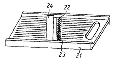
従来より、野菜等を簡単に千切りできる千切りスライサーとして、下記特許文献1に示すような千切りスライサーが知られている(図2参照)。この千切りスライサーは、上面に野菜等の被調理物が摺動する摺動面を有する平板状の本体21と、当該本体21の上面に固定され、複数の刃23が立設してなるブレード22と、前記ブレード22に対し被調理物の摺動方向後方に固定され、被調理物の摺動方向前側に刃部を有するブレード24で構成されている。そして、本体21の摺動面に大根やキュウリ等の被調理物を置き、さらにブレード22方向に摺動させ、これによって被調理物にその厚み方向(すなわち、摺動面に対して鉛直方向)の切れ込みを入れるとともに、ブレード24により被調理物を摺動面と平行な面方向にスライスすることによって千切りにすることが出来る。 Conventionally, as a shredder slicer that can easily shred vegetables and the like, a shredder slicer as shown in the following
従来の千切りスライサーは、被調理物の摺動面が一面であるため、一方向の切り込みとスライス面しか入らないため、被調理物を千切りに切断することしかできなかった。このため、被調理物の具材によっては、細の目切りが必要な場合は、千切りを行った後、再度包丁やカッターなどで、千切りした被調理物を細の目状に切断しなければならず、非常に手間と時間を要していた。 Since the conventional shredded slicer has only one sliding surface of the object to be cooked, it can only cut the object to be shredded because it can only be cut and sliced in one direction. For this reason, depending on the ingredients of the item to be cooked, if fine cuts are required, cut the pieces to be cooked with a knife or a cutter and cut them into fine pieces. It took a lot of time and effort.
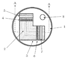
そこで本発明では、スライサー本体1の上面に、被調理物が摺動する摺動面a(2)と、摺動面b(3)の中心軸線が直交するように配置され、摺動面a、b(2,3)の各上面の所定位置に、被調理物に摺動面に対して鉛直方向の切れ込みを入れる第1のブレードをそれぞれ一箇所以上設け(第1ブレード(4)及び第3ブレード(6))、さらに、当該被調理物に摺動面と平行な面方向の切れ込みを入れる第2のブレードをそれぞれ一箇所以上設けた(第2ブレード(5)及び第4ブレード(7))、ことを特徴とする細の目スライサーが得られる。
さらに、スライサー本体1の上面に設けた第1のブレードは、摺動面a(2)上面に固定され複数の刃が立設されて成る第1ブレード4と、摺動面b(3)上面に固定され複数の刃が立設されてなる第3ブレード6とで構成されており、また、スライサー本体1の上面に設けた第2のブレードは、摺動面a(2)上面であって、当該摺動面a(2)に対して鉛直方向に所定距離を隔てられており、上記第1ブレード4に対し被調理物の摺動方向後方に固定され、かつ第1ブレード4が設けられている位置方向に刃先が向いている第2ブレード5と、摺動面b(3)上面であって、当該摺動面b(3)に対して鉛直方向に所定距離を隔てられ、上記第3ブレード6に対し被調理物の摺動方向後方に固定され、かつ第3ブレード6が設けられている位置方向に刃先が向いている第4ブレード7とで構成されている、ことを特徴とする細の目スライサーが得られる。Therefore, in the present invention, the sliding surface a (2) on which the object to be slid slides and the central axis of the sliding surface b (3) are arranged on the upper surface of the
Further, the first blade provided on the upper surface of the
本発明の細の目スライサーによれば、被調理物をカットする際、スライサー本体上面に設けた摺動面a,bを交互に往復摺動させることにより、被調理物の細の目切りカットが簡単に行うことができる。すなわち、従来のスライサーは千切りカットを行った後、これを再度包丁やナイフを用いて、細の目状にカットを行わなければならず、非常に効率が悪く、多くの作業時間を要していた。しかし、本発明によるスライサーによれば、スライサー本体1上面に直交して設けた摺動面a、b上を、被調理物を交互に摺動させる毎に、細の目状にカットすることができる。 According to the fine eye slicer of the present invention, when the object to be cooked is cut, the sliding surfaces a and b provided on the upper surface of the slicer main body are alternately slid back and forth, thereby finely cutting the object to be cooked. Can be done easily. In other words, a conventional slicer must be cut into small pieces using a knife or knife after cutting it into pieces, which is very inefficient and requires a lot of work time. It was. However, according to the slicer according to the present invention, the sliding surfaces a and b provided orthogonally to the upper surface of the
以下、本発明を実施するための最良の形態について、図1を参照しつつ説明する。スライサー本体1は、略円形の平板状の形態からなり、本発明のスライサーによって細の目状にカットされた被調理物を収容する容器(例えば、金属製或いはプラスチック製の調理用ボウルなど)の上面に蓋のように収まる形状をしている。また、装着したスライサー本体をボウルから着脱しやすいように、本体には手指の挿入穴8が設けられている。 Hereinafter, the best mode for carrying out the present invention will be described with reference to FIG. The
さらに、スライサー本体1には、胡瓜や玉ねぎなどの被調理物をカットする際に用いるブレードを備えた摺動面a(2)と、同じくブレードを備えた摺動面b(3)とが、各摺動面の中心軸線が直交するように配置されている。 Furthermore, the
摺動面a(2)の上面の所定位置には、被調理物に摺動面に対して鉛直方向の切れ込みを入れる複数の固定刃が立設する第1ブレード(4)が設けられている。また、摺動面a(2)の摺動方向の一端部には、被調理物に摺動面と平行な面方向に切れ込みを入れる固定刃を設置した第2ブレード(5)が設けられている。 A first blade (4) is provided at a predetermined position on the upper surface of the sliding surface a (2). The first blade (4) is provided with a plurality of stationary blades for making a cut in the vertical direction with respect to the sliding surface. . In addition, a second blade (5) is provided at one end of the sliding surface a (2) in the sliding direction. The second blade (5) is provided with a fixed blade that cuts the object to be cooked in a plane direction parallel to the sliding surface. Yes.
ここで、摺動面a(2)の上面に設けた上記第1ブレード4は、第2ブレード5が形成された摺動面aの端部から、摺動面a(2)及びb(3)の直交部寄りにやや離間して設けられている。また、第2ブレード5の刃先は、当該直交部方向(すなわち、第1ブレード4の設置方向)に向かって設置されているため、当該直交部から第2ブレード5方向に向かって被調理物を摺動させた際に、摺動面と平行な面方向に切れ込みが入るが、その逆、すなわち第2ブレード5の設置された端部から当該直交部方向に向かって摺動させても、被調理部はカットされない構造となっている。 Here, the
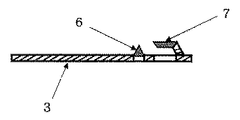
次に、摺動面b(3)上面の所定位置にも、上記摺動面a(2)と同様に、被調理物に摺動面に対して鉛直方向に切れ込みを入れる複数の固定刃が立設された第3ブレード(6)が設けられている。また、摺動面b(3)の摺動方向の一端部にも、被調理物に摺動面と平行な面方向に切れ込みを入れる固定刃が形成された第4ブレード(7)が設けられている。 Next, at a predetermined position on the upper surface of the sliding surface b (3), similarly to the sliding surface a (2), there are a plurality of fixed blades that cut into the cooking object in the vertical direction with respect to the sliding surface. A standing third blade (6) is provided. Moreover, the 4th blade (7) in which the fixed blade which cuts into a to-be-cooked object in the surface direction parallel to a sliding surface was provided also in the one end part of the sliding direction of the sliding surface b (3). ing.
また、摺動面b(3)の上面に設けた上記第3ブレード6は、第4ブレード7が形成された摺動面b(3)の端部から、摺動面a及びbの直交部寄りにやや離間して設けられている。また、第4ブレード7の刃先は、当該直交部方向(すなわち、第3ブレード6の設けられている位置方向)に向かって設置されているため、当該直交部から第4ブレード7方向に向かって被調理物を摺動させた際に、摺動面と平行な面方向に切れ込みが入るが、その逆、すなわち第4ブレード7の設置された端部から当該直交部方向に向かって摺動させても、被調理物はカットされない構造となっている。 Further, the
なお、摺動面a及びbのいずれの面にも、摺動方向に沿って複数の筋状の凸部が設けられている。これにより、被調理物をカットする際に各ブレードに向かって被調理物が円滑にガイドされるとともに、摺動の際の被調理物と摺動面との摩擦が軽減されスムーズに動かすことができる。 Note that a plurality of streak-shaped convex portions are provided along the sliding direction on any of the sliding surfaces a and b. As a result, the food to be cooked is smoothly guided toward the blades when cutting the food to be cooked, and the friction between the food to be cooked and the sliding surface at the time of sliding can be reduced and moved smoothly. it can.
さらに、本発明に係るスライサーは、前記各ブレードを設けた摺動面を設置するスライサー本体1を略円形に形成しているため、調理用ボウルの内側に本体1を嵌め込むようにセットし、カットした被調理物を調理用ボウル内に落として収容することができる。これにより、細の目切りされた被調理物は、調理する際に周囲に飛び散ることもなく、そのままボウル内で調味、調理等の作業を容易に進めることができる。 Furthermore, the slicer according to the present invention is formed so that the
なお、上記の実施例では、スライサー本体1を略円形に形成しているが、この形状に限定されるものではなく、カットした被調理物を収容する容器の形状に合わせて、長方形や正方形、楕円形など互いに直交する摺動面a、bが設けられる面積を確保できる大きさの形状であれば、これら以外の様々な本体形状を採用することができる。 In addition, in said Example, although the slicer
次に、第1及び第3ブレードは、摺動面a、bに対して鉛直方向(すなわち、上面方向)に刃先が向けられ据えられている。しかも、摺動面を横切るようにほぼ一列に複数の刃が立設されている。このため、被調理物を各摺動面上を長さ方向(前後方向)に摺動させると、被調理物は摺動面に対して鉛直方向(その厚み方向)に刃の数に応じて複数の切れ込みが入る。 Next, the first and third blades are placed with their cutting edges directed in the vertical direction (that is, the upper surface direction) with respect to the sliding surfaces a and b. In addition, a plurality of blades are erected substantially in a row so as to cross the sliding surface. For this reason, if a to-be-cooked object is slid on each sliding surface in the length direction (front-rear direction), the to-be-cooked object is perpendicular to the sliding surface (in its thickness direction) according to the number of blades. Multiple cuts are made.
また、第2ブレード5、第4ブレード7は、摺動面a、bの上面であって、当該摺動面より鉛直方向にやや離間して、かつ各端部近傍に摺動面を横に跨ぐ方向に一枚刃が設けられている。しかも、刃先は、各摺動面の直交部方向(すなわち、第1ブレード4又は第3ブレード6の設けられている位置方向)に向かって設置されている。 Further, the
次に、本発明に係る細の目スライサーの使用法を説明する。まず、被調理物を第2ブレード5の外側付近に載置し、これを上から軽く押さえつつ摺動面a(2)を摺動面a,b直交部方向に向けて摺動させる。これにより、被調理物は摺動面a(2)上に設置した第1ブレード4を通過する際、鉛直方向(すなわち、被調理物の厚み方向)に複数の切れ込みが入る。なお、第2ブレード5通過時には、前述のように刃先の向きと摺動方向とが同一のため、第2ブレードによって被調理物がカットされることはない。 Next, the usage of the fine eye slicer according to the present invention will be described. First, the object to be cooked is placed near the outside of the
次に、上記直交部を通過させた被調理物を、そのままの状態を保持しつつ90度角度を変えて、摺動面b(3)に向けて摺動させる。その後、第3ブレード6を通過する際に、摺動面b(3)の鉛直方向(すなわち、被調理物の厚み方向)であって、かつ、第1ブレード4による最初の切れ込みと交差する二度目の切れ込みを入れる。そして、被調理物は摺動面b(3)の端部近傍に設置された第4ブレード7によって、当該摺動面と平行な面方向にスライスされ、最終的に細の目状にカットされ、スライサー本体1下のボウル内に落下する。 Next, the object to be cooked that has passed through the orthogonal part is slid toward the sliding surface b (3) by changing the angle by 90 degrees while maintaining the state as it is. Thereafter, when passing through the
さらに、上記動作の後、第4ブレード7を通過した被調理物を、今度は逆方向、すなわち前記直交部方向に向けて再び摺動させる。これにより、被調理物は、第3ブレード6により摺動面b(3)に対して鉛直方向(すなわち、被調理物の厚み方向)の切れ込みが入る。その後、被調理物をそのままの状態を保持しつつ、前記直交部を通過させた後、摺動方向を摺動面a(2)方向に変換させ、その端部方向に摺動させる。 Further, after the above operation, the object to be cooked that has passed through the
すると、摺動面a(2)上面に設けた第1ブレード(4)により、再び鉛直方向(すなわち、被調理物の厚み方向)であって、しかも、今度は第3ブレード6による最初の切れ込みとほぼ交差する二度目の切れ込みが入ることになる。さらに、第2ブレード5を通過する際に、摺動面と平行な面方向の切れ込みが入れられる。これら一連の動作により、最終的に被調理物は、上記の最初の作業時と同様に細の目状にカットされ、スライサー本体1下の調理用ボウル内に落下する。 Then, the first blade (4) provided on the upper surface of the sliding surface a (2) is again in the vertical direction (that is, the thickness direction of the object to be cooked), and this time, the first cut by the
このように、本発明の細の目スライサーによれば、被調理物を摺動面a,b上を往復摺動させるだけで、野菜等の被調理物の細の目切りを簡単かつ効率的に作ることができる。 As described above, according to the fine eye slicer of the present invention, it is easy and efficient to finely cut the food to be cooked such as vegetables simply by reciprocating the food to be cooked on the sliding surfaces a and b. Can be made.
本発明は、野菜や果物等の切断可能な材料(被調理物)を切断する為の台所用器具であって、スライサー本体部と、その上を切断可能な被調理物が前後移動することができる摺動面と、切断の為のブレードを備え、摺動面上を前後方向にブレードに向かって移動させて、被調理物を簡易な動作で容易に細の目切りを行うことのできる台所用器具の分野での利用が可能である。 The present invention is a kitchen utensil for cutting a severable material (cooked material) such as vegetables and fruits, and the slicer main body part and the uncooked food that can be cut on the slicer body can move back and forth. A kitchen that has a sliding surface that can be cut and a blade for cutting, and can be easily cut into small pieces by a simple operation by moving the sliding surface forward and backward toward the blade. It can be used in the field of appliances.
1 スライサー本体
2 摺動面a
3 摺動面b
4 第1ブレード
5 第2ブレード
6 第3ブレード
7 第4ブレード
8 スライサー本体取り外し用穴1
3 Sliding surface b
4
Claims (2)
さらに、スライサー本体1の上面に設けた第2のブレードは、摺動面a(2)上面であって、当該摺動面a(2)に対して鉛直方向に所定距離を隔てられており、上記第1ブレード4に対し被調理物の摺動方向後方に固定され、かつ第1ブレード4が設けられている位置方向に刃先が向いている第2ブレード5と、摺動面b(3)上面であって、当該摺動面b(3)に対して鉛直方向に所定距離を隔てられ、上記第3ブレード6に対し被調理物の摺動方向後方に固定され、かつ第3ブレード6が設けられている位置方向に刃先が向いている第4ブレード7とで構成されていることを特徴とする細の目スライサー。2. The fine eye slicer according to claim 1, wherein the first blade provided on the upper surface of the slicer main body 1 is fixed to the upper surface of the sliding surface a (2) and has a plurality of blades standing upright. The third blade 6 is fixed to the upper surface of the sliding surface b (3) and has a plurality of blades standing upright.
Furthermore, the second blade provided on the upper surface of the slicer body 1 is the upper surface of the sliding surface a (2), and is separated from the sliding surface a (2) by a predetermined distance in the vertical direction. A second blade 5 which is fixed to the rear side in the sliding direction of the object to be cooked with respect to the first blade 4 and whose cutting edge faces in the position direction where the first blade 4 is provided; and a sliding surface b (3) It is an upper surface, is spaced a predetermined distance in the vertical direction with respect to the sliding surface b (3), is fixed to the rear of the cooking object in the sliding direction with respect to the third blade 6, and the third blade 6 is A fine eye slicer comprising a fourth blade 7 having a blade edge facing the provided position direction.
Priority Applications (1)
| Application Number | Priority Date | Filing Date | Title |
|---|---|---|---|
| JP2015014752A JP2016128200A (en) | 2015-01-09 | 2015-01-09 | Fine slicer |
Applications Claiming Priority (1)
| Application Number | Priority Date | Filing Date | Title |
|---|---|---|---|
| JP2015014752A JP2016128200A (en) | 2015-01-09 | 2015-01-09 | Fine slicer |
Publications (1)
| Publication Number | Publication Date |
|---|---|
| JP2016128200A true JP2016128200A (en) | 2016-07-14 |
Family
ID=56383968
Family Applications (1)
| Application Number | Title | Priority Date | Filing Date |
|---|---|---|---|
| JP2015014752A Pending JP2016128200A (en) | 2015-01-09 | 2015-01-09 | Fine slicer |
Country Status (1)
| Country | Link |
|---|---|
| JP (1) | JP2016128200A (en) |
Cited By (2)
| Publication number | Priority date | Publication date | Assignee | Title |
|---|---|---|---|---|
| KR102085728B1 (en) * | 2018-09-28 | 2020-03-06 | 한영미 | Apparatus of multi functional slice cutter |
| WO2024167014A1 (en) * | 2023-02-10 | 2024-08-15 | 雄一 星 | Vegetable cutting tool |
Citations (3)
| Publication number | Priority date | Publication date | Assignee | Title |
|---|---|---|---|---|
| JP2004034283A (en) * | 2002-07-07 | 2004-02-05 | Shuichi Kitamura | Mincing tool |
| JP2004243508A (en) * | 2003-02-10 | 2004-09-02 | Takaaki Katakura | Method and tool for cutting into fine piece |
| JP2005074619A (en) * | 2003-09-01 | 2005-03-24 | Shuichi Kitamura | Food processor |
-
2015
- 2015-01-09 JP JP2015014752A patent/JP2016128200A/en active Pending
Patent Citations (3)
| Publication number | Priority date | Publication date | Assignee | Title |
|---|---|---|---|---|
| JP2004034283A (en) * | 2002-07-07 | 2004-02-05 | Shuichi Kitamura | Mincing tool |
| JP2004243508A (en) * | 2003-02-10 | 2004-09-02 | Takaaki Katakura | Method and tool for cutting into fine piece |
| JP2005074619A (en) * | 2003-09-01 | 2005-03-24 | Shuichi Kitamura | Food processor |
Cited By (2)
| Publication number | Priority date | Publication date | Assignee | Title |
|---|---|---|---|---|
| KR102085728B1 (en) * | 2018-09-28 | 2020-03-06 | 한영미 | Apparatus of multi functional slice cutter |
| WO2024167014A1 (en) * | 2023-02-10 | 2024-08-15 | 雄一 星 | Vegetable cutting tool |
Similar Documents
| Publication | Publication Date | Title |
|---|---|---|
| US5626067A (en) | Slicer guide | |
| US20120085249A1 (en) | Assembled peeler | |
| US2355312A (en) | Vegetable cutter | |
| JP2016128200A (en) | Fine slicer | |
| US2786503A (en) | Fruit and vegetable cutter and grater | |
| CN205310323U (en) | Multi -functional shredder of hand held | |
| CN104802200B (en) | Manual vegetable cutter | |
| US10160130B2 (en) | Cutting board assembly | |
| KR20170014485A (en) | Multi-function food cutting apparatus | |
| JP3209907U (en) | Cutting instrument | |
| CN205325754U (en) | A cutting tool for slicing and slicing equipment | |
| JP3222803U (en) | Cooking slicer | |
| KR101163652B1 (en) | A Vegetables Cutter which cuts small | |
| KR200432126Y1 (en) | Cutter structure for diced cutting of sliced vegetable cutter | |
| KR101163480B1 (en) | Kitchen knife capable of horizontal cutting easily | |
| CN105729543A (en) | Food slicing device | |
| KR101460201B1 (en) | A kitchen knife using multiple blades | |
| CN211541320U (en) | Integrated manual slicing and shredding device | |
| KR200443620Y1 (en) | Cutter for making bulb noodles | |
| US20250289156A1 (en) | Food slicer | |
| KR200166356Y1 (en) | A knife | |
| CN204209709U (en) | Multifunctional vegetable cutter | |
| RU2704430C1 (en) | Cutting knife and method of its application | |
| JPH0616704Y2 (en) | Vegetable cooker | |
| JP3172247U (en) | Cutting board |
Legal Events
| Date | Code | Title | Description |
|---|---|---|---|
| A621 | Written request for application examination |
Free format text: JAPANESE INTERMEDIATE CODE: A621 Effective date: 20170116 |
|
| A977 | Report on retrieval |
Free format text: JAPANESE INTERMEDIATE CODE: A971007 Effective date: 20171110 |
|
| A131 | Notification of reasons for refusal |
Free format text: JAPANESE INTERMEDIATE CODE: A131 Effective date: 20171121 |
|
| A02 | Decision of refusal |
Free format text: JAPANESE INTERMEDIATE CODE: A02 Effective date: 20180529 |