JP2016127631A - Solar panel unit - Google Patents
Solar panel unit Download PDFInfo
- Publication number
- JP2016127631A JP2016127631A JP2014264579A JP2014264579A JP2016127631A JP 2016127631 A JP2016127631 A JP 2016127631A JP 2014264579 A JP2014264579 A JP 2014264579A JP 2014264579 A JP2014264579 A JP 2014264579A JP 2016127631 A JP2016127631 A JP 2016127631A
- Authority
- JP
- Japan
- Prior art keywords
- power generation
- air
- chamber
- generation panel
- photovoltaic power
- Prior art date
- Legal status (The legal status is an assumption and is not a legal conclusion. Google has not performed a legal analysis and makes no representation as to the accuracy of the status listed.)
- Granted
Links
Images


Classifications
-
- Y—GENERAL TAGGING OF NEW TECHNOLOGICAL DEVELOPMENTS; GENERAL TAGGING OF CROSS-SECTIONAL TECHNOLOGIES SPANNING OVER SEVERAL SECTIONS OF THE IPC; TECHNICAL SUBJECTS COVERED BY FORMER USPC CROSS-REFERENCE ART COLLECTIONS [XRACs] AND DIGESTS
- Y02—TECHNOLOGIES OR APPLICATIONS FOR MITIGATION OR ADAPTATION AGAINST CLIMATE CHANGE
- Y02E—REDUCTION OF GREENHOUSE GAS [GHG] EMISSIONS, RELATED TO ENERGY GENERATION, TRANSMISSION OR DISTRIBUTION
- Y02E10/00—Energy generation through renewable energy sources
- Y02E10/50—Photovoltaic [PV] energy
Landscapes
- Fluid-Pressure Circuits (AREA)
Abstract
Description
本発明は、太陽光パネルユニットに関するものである。 The present invention relates to a solar panel unit.
従来より、太陽光パネルユニットにおいて、太陽光発電パネルを回転軸に対して角度調整するために、エアシリンダ等の空気圧アクチュエータを用いた構成が知られている(例えば、特許文献1参照)。 2. Description of the Related Art Conventionally, in a solar panel unit, a configuration using a pneumatic actuator such as an air cylinder is known in order to adjust the angle of a photovoltaic power generation panel with respect to a rotation axis (see, for example, Patent Document 1).
このような空気圧アクチュエータを用いた太陽光パネルユニットにおいて、太陽光発電パネルに対して風などの外力が作用した場合には、空気圧アクチュエータのシリンダ室内の空気が圧縮されて太陽光発電パネルが外力のままに動かされることとなる。これにより、太陽光発電パネルを支持している支持架台に加わる力を小さくすることができる。 In a solar panel unit using such a pneumatic actuator, when an external force such as wind acts on the photovoltaic power generation panel, the air in the cylinder chamber of the pneumatic actuator is compressed and the photovoltaic power generation panel It will be moved as it is. Thereby, the force added to the support stand which supports the photovoltaic power generation panel can be made small.
一方、太陽光発電パネルに対して外力が作用しなくなった場合には、シリンダ室内で圧縮された空気のバネ作用によって、太陽光発電パネルを元の揺動位置に戻すことができる。 On the other hand, when the external force no longer acts on the photovoltaic power generation panel, the photovoltaic power generation panel can be returned to the original swinging position by the spring action of the air compressed in the cylinder chamber.
ところで、外力が作用して太陽光発電パネルが動かされると、シリンダ室内の圧力が上昇し、それに比例した抵抗力が発生することとなる。その結果、太陽光発電パネルが揺動しにくくなるとともに、空気圧アクチュエータが破損するおそれがある。そこで、空気の給排通路にリリーフ弁を接続し、リリーフ圧に達したときに外部に空気を排出させることで、シリンダ室内の圧力の上昇を抑えるようにした構成を採用することが考えられる。 By the way, when an external force is applied and the photovoltaic power generation panel is moved, the pressure in the cylinder chamber is increased, and a resistance force proportional to the pressure is generated. As a result, the photovoltaic power generation panel is less likely to swing and the pneumatic actuator may be damaged. In view of this, it is conceivable to employ a configuration in which a relief valve is connected to the air supply / exhaust passage, and when the relief pressure is reached, the air is discharged to the outside, thereby suppressing an increase in pressure in the cylinder chamber.
しかしながら、空気圧アクチュエータの給排通路から外部に空気が排出されてしまうと、太陽光発電パネルに外力が作用しなくなった場合に、シリンダ室内で圧縮された空気のバネ作用が小さくなってしまう。その結果、太陽光発電パネルが元の揺動位置まで戻りきらなくなるという問題がある。 However, if air is discharged to the outside from the supply / discharge passage of the pneumatic actuator, the spring action of the air compressed in the cylinder chamber is reduced when no external force acts on the photovoltaic power generation panel. As a result, there is a problem that the photovoltaic power generation panel cannot return to the original swing position.
本発明は、かかる点に鑑みてなされたものであり、その目的は、太陽光発電パネルに対して外力が作用した場合に太陽光発電パネルを揺動させやすくするとともに、外力が作用しなくなった場合に太陽光発電パネルを元の揺動位置に戻しやすくすることにある。 The present invention has been made in view of such a point, and the purpose thereof is to make it easier to rock the photovoltaic power generation panel when an external force is applied to the photovoltaic power generation panel, and the external force is no longer applied. In this case, the photovoltaic power generation panel can be easily returned to the original swing position.
本発明は、太陽光発電パネル(11)と、該太陽光発電パネル(11)を所定の回転軸(S)周りに揺動させるアクチュエータ(50)とを備えた太陽光パネルユニットを対象とし、次のような解決手段を講じた。 The present invention is directed to a solar panel unit including a solar power generation panel (11) and an actuator (50) that swings the solar power generation panel (11) around a predetermined rotation axis (S). The following solutions were taken.
すなわち、第1の発明は、前記アクチュエータ(50)は、シリンダ本体(51)と、該シリンダ本体(51)内に摺動自在に嵌め込まれて該シリンダ本体(51)内を第1及び第2のシリンダ室(56,57)に区画するピストン(52)と、該ピストン(52)の移動に伴って前記太陽光発電パネル(11)を揺動させる出力軸(55)とを有し、
前記シリンダ本体(51)には、前記第1及び第2のシリンダ室(56,57)に空気を給排する第1及び第2の給排通路(64,65)が接続され、
前記第1及び第2の給排通路(64,65)には、前記ピストン(52)の移動に伴って前記シリンダ本体(51)の外部に排気される空気を貯留可能な第1及び第2のチャンバ部(66,67)が接続されていることを特徴とするものである。
That is, in the first invention, the actuator (50) is slidably fitted into the cylinder body (51) and the cylinder body (51), and the cylinder body (51) has first and second insides. A piston (52) partitioned into a cylinder chamber (56, 57) and an output shaft (55) for swinging the photovoltaic power generation panel (11) as the piston (52) moves.
Connected to the cylinder body (51) are first and second supply / discharge passages (64, 65) for supplying and discharging air to and from the first and second cylinder chambers (56, 57),
In the first and second supply / discharge passages (64, 65), first and second air that can store air exhausted to the outside of the cylinder body (51) as the piston (52) moves. These chamber portions (66, 67) are connected.
第1の発明では、シリンダ本体(51)に空気を給排する第1及び第2の給排通路(64,65)には、第1及び第2のチャンバ部(66,67)が接続される。そして、ピストン(52)の移動に伴ってシリンダ本体(51)の外部に排気される空気は、第1及び第2のチャンバ部(66,67)に貯留される。 In the first invention, the first and second chamber portions (66, 67) are connected to the first and second supply / discharge passages (64, 65) for supplying and discharging air to the cylinder body (51). The The air exhausted to the outside of the cylinder body (51) as the piston (52) moves is stored in the first and second chamber portions (66, 67).
これにより、太陽光発電パネル(11)に対して外力が作用した場合には、第1又は第2のシリンダ室(56,57)から第1又は第2のチャンバ部(66,67)に向かって空気が排気されることで、第1又は第2のシリンダ室(56,57)内の圧力が上昇するのを抑え、太陽光発電パネル(11)を揺動させやすくなる。 As a result, when an external force is applied to the photovoltaic power generation panel (11), the first or second cylinder chamber (56, 57) is directed to the first or second chamber section (66, 67). As a result of the air being exhausted, the pressure in the first or second cylinder chamber (56, 57) is prevented from increasing and the photovoltaic power generation panel (11) can be easily swung.
一方、太陽光発電パネル(11)に外力が作用しなくなった場合には、第1又は第2のチャンバ部(66,67)に貯留されている空気によってバネ作用を十分に得ることができるので、太陽光発電パネル(11)を元の揺動位置に戻しやすくなる。 On the other hand, when the external force no longer acts on the photovoltaic power generation panel (11), the spring action can be sufficiently obtained by the air stored in the first or second chamber part (66, 67). It becomes easy to return the photovoltaic power generation panel (11) to the original swinging position.
第2の発明は、第1の発明において、
前記第2のチャンバ部(67)は、前記第1のチャンバ部(66)の内部に収容されるとともに、該第2のチャンバ部(67)への空気の給気又は排気に伴ってその容積が膨張又は収縮するように構成されていることを特徴とするものである。
According to a second invention, in the first invention,
The second chamber part (67) is accommodated in the first chamber part (66), and the volume of the second chamber part (67) is increased as air is supplied to or exhausted from the second chamber part (67). Is configured to expand or contract.
第2の発明では、第2のチャンバ部(67)が第1のチャンバ部(66)の内部に収容されているので、第1及び第2のチャンバ部(66,67)を別々に配設する場合に比べて、設置スペースが小さくて済む。また、膨張側のシリンダ室の負圧を緩和することができるので、アクチュエータ(50)に加わる負荷を低減することができる。 In the second invention, since the second chamber part (67) is accommodated in the first chamber part (66), the first and second chamber parts (66, 67) are separately provided. Compared with the case, the installation space is small. Moreover, since the negative pressure in the cylinder chamber on the expansion side can be relieved, the load applied to the actuator (50) can be reduced.
第3の発明は、第1の発明において、
前記第1及び第2の給排通路(64,65)に接続されたシリンダ部(71)と、該シリンダ部(71)内に嵌め込まれて該シリンダ部(71)内を前記第1及び第2のチャンバ部(66,67)に区画するピストン部(72)とを有するフリーピストン(70)を備えたことを特徴とするものである。
According to a third invention, in the first invention,
A cylinder part (71) connected to the first and second supply / discharge passages (64, 65), and the cylinder part (71) are fitted into the cylinder part (71) so that the first and second A free piston (70) having a piston part (72) partitioned into two chamber parts (66, 67) is provided.
第3の発明では、フリーピストン(70)のシリンダ部(71)内に第1及び第2のチャンバ部(66,67)を設けるようにしたから、第1及び第2のチャンバ部(66,67)を別々に配設する場合に比べて、設置スペースが小さくて済む。 In the third invention, since the first and second chamber portions (66, 67) are provided in the cylinder portion (71) of the free piston (70), the first and second chamber portions (66, 67) are provided. The installation space is smaller than when 67) is provided separately.
本発明によれば、太陽光発電パネル(11)に対して外力が作用した場合には、第1又は第2のシリンダ室(56,57)から第1又は第2のチャンバ部(66,67)に向かって空気が排気されることで、第1又は第2のシリンダ室(56,57)内の圧力が上昇するのを抑え、太陽光発電パネル(11)を揺動させやすくなる。 According to the present invention, when an external force is applied to the photovoltaic power generation panel (11), the first or second chamber portion (66,67) extends from the first or second cylinder chamber (56,57). ), The pressure in the first or second cylinder chamber (56, 57) is prevented from increasing and the photovoltaic power generation panel (11) can be easily swung.
一方、太陽光発電パネル(11)に外力が作用しなくなった場合には、第1又は第2のチャンバ部(66,67)に貯留されている空気によってバネ作用を十分に得ることができるので、太陽光発電パネル(11)を元の揺動位置に戻しやすくなる。 On the other hand, when the external force no longer acts on the photovoltaic power generation panel (11), the spring action can be sufficiently obtained by the air stored in the first or second chamber part (66, 67). It becomes easy to return the photovoltaic power generation panel (11) to the original swinging position.
以下、本発明の実施形態を図面に基づいて説明する。なお、以下の好ましい実施形態の説明は、本質的に例示に過ぎず、本発明、その適用物或いはその用途を制限することを意図するものではない。 Hereinafter, embodiments of the present invention will be described with reference to the drawings. It should be noted that the following description of the preferred embodiment is merely illustrative in nature and is not intended to limit the present invention, its application, or its use.
《実施形態1》
本実施形態は、太陽の位置に合わせて角度が調整される太陽光パネルをそれぞれ有する複数の太陽光パネルユニットを備えた太陽光発電システムに関するものである。太陽光発電システムは、複数台を組み合わせて用いることにより、所謂メガソーラーシステムと呼ばれる大規模太陽光発電システムを構築するものである。
This embodiment relates to a solar power generation system including a plurality of solar panel units each having a solar panel whose angle is adjusted according to the position of the sun. The solar power generation system is configured to construct a large-scale solar power generation system called a so-called mega solar system by using a combination of a plurality of units.
〈システム構成〉
図1に示すように、太陽光発電システム(1)は、それぞれ太陽光発電パネル(11)を有する複数(図1では3つ)の太陽光パネルユニット(10)を備えている。複数の太陽光パネルユニット(10)は、東西方向に一直線上に並ぶ設置位置に、互いの太陽光発電パネル(11)の回転軸(S)が平行となるように設置されている。
<System configuration>
As shown in FIG. 1, the solar power generation system (1) includes a plurality (three in FIG. 1) of solar panel units (10) each having a solar power generation panel (11). The plurality of solar panel units (10) are installed at installation positions arranged in a straight line in the east-west direction so that the rotation axes (S) of the solar power generation panels (11) are parallel to each other.
複数の太陽光パネルユニット(10)は、後述するアクチュエータ機構(40)が設けられてアクチュエータ(50)によって太陽光発電パネル(11)が回転軸(S)周りに回動するように駆動される1つの第1太陽光パネルユニット(10a)と、アクチュエータ機構(40)が設けられない複数(図1では2つのみ図示)の第2太陽光パネルユニット(10b)とによって構成されている。 The plurality of solar panel units (10) are provided with an actuator mechanism (40) to be described later, and are driven by the actuator (50) so that the solar power generation panel (11) rotates around the rotation axis (S) One first solar panel unit (10a) and a plurality of second solar panel units (10b) (only two are shown in FIG. 1) not provided with the actuator mechanism (40) are configured.
詳細については後述するが、第1太陽光パネルユニット(10a)と第2太陽光パネルユニット(10b)とは、アクチュエータ(50)を含むアクチュエータ機構(40)を有するか否かを除いては実質的に同じように構成されている。 Although details will be described later, the first solar panel unit (10a) and the second solar panel unit (10b) are substantially the same except whether or not the actuator mechanism (40) including the actuator (50) is included. In the same way.
また、複数の太陽光パネルユニット(10)は、連結ロッド(20)によって、回動動作が同期するように連結されている。なお、図示を省略しているが、太陽光発電システム(1)には、複数の太陽光パネルユニット(10)で発電した直流電力を交流電力に変換するパワーコンディショナが設けられている。 Moreover, the some solar panel unit (10) is connected so that rotation operation | movement may synchronize by the connection rod (20). Although not shown, the solar power generation system (1) is provided with a power conditioner that converts DC power generated by the plurality of solar panel units (10) into AC power.
〈太陽光パネルユニット〉
太陽光パネルユニット(10)は、太陽光発電パネル(11)と、太陽光発電パネル(11)を回転軸(S)周りに回動自在に支持する支持架台(12)とをそれぞれ有している。
<Solar panel unit>
The solar panel unit (10) includes a solar power generation panel (11) and a support base (12) that rotatably supports the solar power generation panel (11) around the rotation axis (S). Yes.
太陽光発電パネル(11)は、略板状に形成され、上面が太陽光の受光面(11a)に構成されている。太陽光発電パネル(11)は、太陽光を受光面(11a)に受けることによって直流電力を発生するように構成されている。太陽光発電パネル(11)は、水平面に対し、南北方向において北側ほど高くなるように傾斜した状態で、支持架台(12)に支持されている。 The photovoltaic power generation panel (11) is formed in a substantially plate shape, and its upper surface is configured as a sunlight receiving surface (11a). The solar power generation panel (11) is configured to generate DC power by receiving sunlight on the light receiving surface (11a). The solar power generation panel (11) is supported by the support frame (12) in a state of being inclined so as to be higher toward the north side in the north-south direction relative to the horizontal plane.
図2に示すように、支持架台(12)は、回動部材(13)と、支持部材(14)とを有する。回動部材(13)は、太陽光発電パネル(11)に固定され、太陽光発電パネル(11)の幅方向の中央部において南北方向に延びる回転軸(S)周りに回動自在に構成されている。 As shown in FIG. 2, the support frame (12) includes a rotating member (13) and a support member (14). The rotating member (13) is fixed to the photovoltaic power generation panel (11), and is configured to be rotatable around a rotation axis (S) extending in the north-south direction at the center in the width direction of the photovoltaic power generation panel (11). ing.
具体的には、回動部材(13)は、太陽光発電パネル(11)に固定された2本の桟部材(15a,15b)と、桟部材(15a,15b)にそれぞれ固定された軸部材(16)と、一方の桟部材(15b)に固定されたリンク部材(17)とを有する。 Specifically, the rotating member (13) includes two crosspiece members (15a, 15b) fixed to the photovoltaic power generation panel (11) and a shaft member fixed to each of the crosspiece members (15a, 15b). (16) and a link member (17) fixed to one of the crosspiece members (15b).
2本の桟部材(15a,15b)は、太陽光発電パネル(11)の受光面(11a)の裏面(11b)に固定され、裏面(11b)に沿って太陽光発電パネル(11)の幅方向(回転軸(S)に垂直な方向)に延びている。2本の桟部材(15a,15b)は、平行に設けられ、上側(北側)の桟部材(15a)には、後述するアクチュエータ機構(40)の伝達機構(43)が連結される一方、下側(南側)の桟部材(15b)には、連結ロッド(20)が取り付けられるリンク部材(17)が固定される。 Two crosspieces (15a, 15b) are fixed to the back surface (11b) of the light receiving surface (11a) of the photovoltaic panel (11), and the width of the photovoltaic panel (11) along the back surface (11b) It extends in the direction (direction perpendicular to the rotation axis (S)). The two crosspieces (15a, 15b) are provided in parallel, and the transmission mechanism (43) of the actuator mechanism (40) described later is coupled to the upper (north) crosspiece (15a), while the lower A link member (17) to which the connecting rod (20) is attached is fixed to the side (south side) crosspiece member (15b).
軸部材(16)は、軸部(16a)と、軸部(16a)の基端部を支持する基台部(16b)とをそれぞれ有している。軸部(16a)は、略円柱形状に形成され、各桟部材(15a,15b)の対向する側面に沿って延びる基台部(16b)から基台部(16b)に略垂直な方向に突出している。 The shaft member (16) includes a shaft portion (16a) and a base portion (16b) that supports the base end portion of the shaft portion (16a). The shaft portion (16a) is formed in a substantially cylindrical shape, and protrudes in a direction substantially perpendicular to the base portion (16b) from the base portion (16b) extending along the opposing side surfaces of the crosspiece members (15a, 15b). ing.
基台部(16b)は、軸部(16a)の軸心が太陽光発電パネル(11)の幅方向の中央に位置するように、ボルトによって桟部材(15a,15b)に固定されている。本実施形態では、この2つの軸部材(16)の軸部(16a)の軸心が回転軸(S)となる。 The base portion (16b) is fixed to the crosspiece members (15a, 15b) with bolts so that the shaft center of the shaft portion (16a) is located at the center in the width direction of the photovoltaic power generation panel (11). In the present embodiment, the axis of the shaft portion (16a) of the two shaft members (16) serves as the rotation shaft (S).
支持部材(14)は、上端部に設けられる支持台部(18)と、支持台部(18)の下端から下方に向かって延びる支柱(19)とを有している。支持台部(18)は、太陽光発電パネル(11)の傾斜方向に延びる鋼材であり、上面の両端から略垂直に上方に立ち上がる2つの起立部(18a)を有している。起立部(18a)は、2つの軸部材(16)の軸部(16a)を回転可能に支持している。これにより、太陽光発電パネル(11)が支持架台(12)に、回転軸(S)周りに回動自在に支持されている。 The support member (14) includes a support base part (18) provided at the upper end part, and a column (19) extending downward from the lower end of the support base part (18). The support base portion (18) is a steel material extending in the inclination direction of the photovoltaic power generation panel (11), and has two upright portions (18a) that rise upward substantially vertically from both ends of the upper surface. The standing portion (18a) rotatably supports the shaft portion (16a) of the two shaft members (16). Thereby, the photovoltaic power generation panel (11) is supported by the support frame (12) so as to be rotatable around the rotation axis (S).
支柱(19)は、固定金具(19a)を介して支持台部(18)に固定される円筒形状の鋼材であり、下端部が地中に埋設される。支持部材(14)は、支柱(19)の下端を、地中に埋設し、その周囲をモルタル等で固めることにより、位置が固定される。 The column (19) is a cylindrical steel material that is fixed to the support base (18) via the fixing bracket (19a), and the lower end is embedded in the ground. The position of the support member (14) is fixed by embedding the lower end of the support column (19) in the ground and hardening its periphery with mortar or the like.
〈アクチュエータ機構〉
図2に示すように、アクチュエータ機構(40)は、アクチュエータ(50)と、アクチュエータ(50)を支持台部(18)に固定する駆動台(42)と、アクチュエータ(50)の出力軸(55)の回転力を太陽光発電パネル(11)に伝達する伝達機構(43)とを有している。
<Actuator mechanism>
As shown in FIG. 2, the actuator mechanism (40) includes an actuator (50), a drive base (42) for fixing the actuator (50) to the support base (18), and an output shaft (55) of the actuator (50). ) Is transmitted to the photovoltaic power generation panel (11).
アクチュエータ(50)は、本実施形態では、回転式の空気圧アクチュエータによって構成されている。アクチュエータ(50)の詳細な構造については後述するが、空気圧によって出力軸(55)を回転させることによって回転力を出力するように構成されている。 In the present embodiment, the actuator (50) is a rotary pneumatic actuator. Although the detailed structure of the actuator (50) will be described later, the actuator (50) is configured to output a rotational force by rotating the output shaft (55) by air pressure.
駆動台(42)は、略L字形状の板状体によって構成され、一辺が支持台部(18)の下面に固定され、他の一辺には、アクチュエータ(50)の出力軸(55)が貫通するようにアクチュエータ(50)が固定されている。 The drive base (42) is configured by a substantially L-shaped plate-like body, one side is fixed to the lower surface of the support base (18), and the output shaft (55) of the actuator (50) is provided on the other side. The actuator (50) is fixed so as to penetrate.
伝達機構(43)は、基端がアクチュエータ(50)の出力軸(55)に連結された第1伝達部材(43a)と、第1伝達部材(43a)の先端に基端がピン部材によって連結され、先端が太陽光発電パネル(11)の上側の桟部材(15a)にピン部材によって連結された第2伝達部材(43b)とを有している。 The transmission mechanism (43) includes a first transmission member (43a) having a proximal end coupled to the output shaft (55) of the actuator (50), and a proximal end coupled to the distal end of the first transmission member (43a) by a pin member. And a second transmission member (43b) whose tip is connected to the upper beam member (15a) of the photovoltaic power generation panel (11) by a pin member.
アクチュエータ(50)が作動すると、第1伝達部材(43a)が出力軸(55)の回転に伴って出力軸(55)周りに回動し、これにより、第2伝達部材(43b)の基端が出力軸(55)周りに回動する。このような第2伝達部材(43b)により、太陽光発電パネル(11)の第2伝達部材(43b)の先端との連結部分が押し上げられる又は引き下げられる。 When the actuator (50) is actuated, the first transmission member (43a) rotates around the output shaft (55) as the output shaft (55) rotates, thereby causing the proximal end of the second transmission member (43b). Rotates around the output shaft (55). The connection part with the front-end | tip of the 2nd transmission member (43b) of a photovoltaic power generation panel (11) is pushed up or pulled down by such a 2nd transmission member (43b).
このようにして、出力軸(55)の回転力が伝達機構(43)によって太陽光発電パネル(11)に伝達され、太陽光発電パネル(11)が回転軸(S)周りに回動する。 Thus, the rotational force of the output shaft (55) is transmitted to the photovoltaic power generation panel (11) by the transmission mechanism (43), and the photovoltaic power generation panel (11) rotates around the rotational axis (S).
〈アクチュエータの構造〉
次に、図3及び図4を参照して、アクチュエータ(50)の内部構造について説明する。なお、図3及び図4では、圧力空気が供給されている空間に黒丸ハッチングを付している。
<Actuator structure>
Next, the internal structure of the actuator (50) will be described with reference to FIGS. In FIG. 3 and FIG. 4, black circle hatching is given to the space to which the pressurized air is supplied.
アクチュエータ(50)は、シリンダ本体(51)と、シリンダ本体(51)内に摺動自在に嵌め込まれた左右一対のピストン(52)と、ピストン(52)の移動に伴って太陽光発電パネル(11)を揺動させる出力軸(55)とを有する。 The actuator (50) includes a cylinder body (51), a pair of left and right pistons (52) slidably fitted in the cylinder body (51), and a photovoltaic panel ( 11) having an output shaft (55) for swinging.
シリンダ本体(51)には、第1及び第2の空気ポート(51a,51b)が形成されている。左右一対のピストン(52)は、シリンダ本体(51)の内部空間が3つの空間に区画されるように所定の間隔をあけて配置されている。これにより、シリンダ本体(51)の左側壁と左側のピストン(52)との間、及びシリンダ本体(51)の右側壁と右側のピストン(52)との間の2つの空間を一体とした第1のシリンダ室(56)が形成され、左右一対のピストン(52)の間に第2のシリンダ室(57)が形成される。 The cylinder body (51) is formed with first and second air ports (51a, 51b). The pair of left and right pistons (52) are arranged at a predetermined interval so that the internal space of the cylinder body (51) is partitioned into three spaces. Thereby, the two spaces between the left side wall of the cylinder body (51) and the left piston (52) and between the right side wall of the cylinder body (51) and the right piston (52) are integrated. One cylinder chamber (56) is formed, and a second cylinder chamber (57) is formed between the pair of left and right pistons (52).
第1の空気ポート(51a)は、第1のシリンダ室(56)に連通している。第2の空気ポート(51b)は、第2のシリンダ室(57)に連通している。 The first air port (51a) communicates with the first cylinder chamber (56). The second air port (51b) communicates with the second cylinder chamber (57).
第2のシリンダ室(57)には、左右一対の可動支持板(53)と、可動支持板(53)に取り付けられた係合ピン(53a)と、駆動板(54)とが配設されている。 In the second cylinder chamber (57), a pair of left and right movable support plates (53), an engagement pin (53a) attached to the movable support plate (53), and a drive plate (54) are disposed. ing.
左右一対の可動支持板(53)は、細長の矩形板状に形成され、シリンダ本体(51)の幅方向において互いに対向するように配置されている。また、左右一対の可動支持板(53)の基端部は、左右一対のピストン(52)にそれぞれ固定されている。 The pair of left and right movable support plates (53) are formed in an elongated rectangular plate shape and are disposed so as to face each other in the width direction of the cylinder body (51). The base end portions of the pair of left and right movable support plates (53) are fixed to the pair of left and right pistons (52), respectively.
係合ピン(53a)は、左右一対の可動支持板(53)の先端部にそれぞれ立設されている。駆動板(54)は、細長の矩形板状に形成され、第2のシリンダ室(57)の中央部に配置されている。また、駆動板(54)の両端部には、係合ピン(53a)と係合可能な凹状の係合溝(54a)がそれぞれ形成されている。 The engagement pin (53a) is erected at the tip of the pair of left and right movable support plates (53). The drive plate (54) is formed in the shape of an elongated rectangular plate, and is disposed at the center of the second cylinder chamber (57). In addition, concave engagement grooves (54a) that can be engaged with the engagement pins (53a) are formed at both ends of the drive plate (54), respectively.
出力軸(55)は、その軸心が駆動板(54)に対して垂直となるように、シリンダ本体(51)を貫通して駆動板(54)の中央部に固定されている。 The output shaft (55) passes through the cylinder body (51) and is fixed to the center portion of the drive plate (54) so that its axis is perpendicular to the drive plate (54).
図3に示すように、第1の空気ポート(51a)が空気タンク(62)(図5参照)と連通し、第2の空気ポート(51b)が大気と連通すると、第1の空気ポート(51a)から第1のシリンダ室(56)内に圧力空気が供給され、第2のシリンダ室(57)から第2の空気ポート(51b)を経由して大気に圧力空気が排出される。 As shown in FIG. 3, when the first air port (51a) communicates with the air tank (62) (see FIG. 5) and the second air port (51b) communicates with the atmosphere, the first air port ( Pressure air is supplied into the first cylinder chamber (56) from 51a), and the pressure air is discharged from the second cylinder chamber (57) to the atmosphere via the second air port (51b).
これにより、左右一対のピストン(52)は、互いに近づく方向に移動する。このとき、左右一対の可動支持板(53)も互いに近づく方向に移動する。そして、可動支持板(53)の先端部に設けられた係合ピン(53a)と駆動板(54)の係合溝(54a)との係合により、駆動板(54)及び出力軸(55)が反時計回りに回転(揺動)する。 As a result, the pair of left and right pistons (52) move in a direction approaching each other. At this time, the pair of left and right movable support plates (53) also move in a direction approaching each other. The drive plate (54) and the output shaft (55) are engaged by the engagement between the engagement pin (53a) provided at the tip of the movable support plate (53) and the engagement groove (54a) of the drive plate (54). ) Rotates (oscillates) counterclockwise.
一方、図4に示すように、第1の空気ポート(51a)が大気と連通し、第2の空気ポート(51b)が空気タンク(62)(図5参照)と連通すると、空気タンク(62)から第2の空気ポート(51b)を経由して第2のシリンダ室(57)に圧力空気が供給され、第1のシリンダ室(56)から第1の空気ポート(51a)を経由して大気に圧力空気が排出される。 On the other hand, as shown in FIG. 4, when the first air port (51a) communicates with the atmosphere and the second air port (51b) communicates with the air tank (62) (see FIG. 5), the air tank (62 ) Is supplied to the second cylinder chamber (57) via the second air port (51b) and from the first cylinder chamber (56) via the first air port (51a). Pressure air is discharged to the atmosphere.
これにより、左右一対のピストン(52)は、互いに離間する方向に移動する。このとき、左右一対の可動支持板(53)も互いに離間する方向に移動する。そして、可動支持板(53)の先端部に設けられた係合ピン(53a)と駆動板(54)の係合溝(54a)との係合により、駆動板(54)及び出力軸(55)が時計回りに回転(揺動)する。 As a result, the pair of left and right pistons (52) move away from each other. At this time, the pair of left and right movable support plates (53) also move away from each other. The drive plate (54) and the output shaft (55) are engaged by the engagement between the engagement pin (53a) provided at the tip of the movable support plate (53) and the engagement groove (54a) of the drive plate (54). ) Rotates (swings) clockwise.
〈空気回路〉
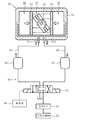
図5に示すように、空気回路(60)は、空気圧縮機(61)と、空気タンク(62)と、三方向切換弁(63)と、三方向切換弁(63)とアクチュエータ(50)とを繋いで空気を給排する第1及び第2の給排通路(64,65)と、第1及び第2の給排通路(64,65)に接続された第1及び第2のチャンバ部(66,67)と、三方向切換弁(63)の切り換え動作を制御する制御部(68)とを備えている。
<Air circuit>
As shown in FIG. 5, the air circuit (60) includes an air compressor (61), an air tank (62), a three-way selector valve (63), a three-way selector valve (63), and an actuator (50). Are connected to the first and second supply / discharge passages (64, 65), and the first and second chambers connected to the first and second supply / discharge passages (64, 65). Section (66, 67) and a control section (68) for controlling the switching operation of the three-way switching valve (63).
空気圧縮機(61)は、所定圧力の圧力空気を吐出するように構成されている。空気タンク(62)は、空気圧縮機(61)から吐出された圧力空気を貯留し、圧力空気を三方向切換弁(63)に供給している。 The air compressor (61) is configured to discharge pressurized air having a predetermined pressure. The air tank (62) stores the pressure air discharged from the air compressor (61) and supplies the pressure air to the three-way switching valve (63).
三方向切換弁(63)は、制御部(68)による制御に応答して、アクチュエータ(50)と、空気タンク(62)又は大気との間の空気通路を切り換え可能に構成されている。 The three-way switching valve (63) is configured to be able to switch the air passage between the actuator (50) and the air tank (62) or the atmosphere in response to control by the control unit (68).
具体的には、三方向切換弁(63)は、アクチュエータ(50)の第1の空気ポート(51a)が空気タンク(62)と連通してアクチュエータ(50)の第2の空気ポート(51b)が大気と連通する第1の経路と、第1の空気ポート(51a)が大気と連通して第2の空気ポート(51b)が空気タンク(62)と連通する第2の経路と、第1及び第2の空気ポート(51a,51b)の両方が閉塞される第3の経路とを切り換える。 Specifically, the three-way switching valve (63) includes a second air port (51b) of the actuator (50) in which the first air port (51a) of the actuator (50) communicates with the air tank (62). A first path in which the first air port (51a) communicates with the atmosphere, and a second path in which the second air port (51b) communicates with the air tank (62); And the third path in which both the second air ports (51a, 51b) are closed.
ここで、三方向切換弁(63)は、第1又は第2の経路に切り換えられて太陽光発電パネル(11)が所定の方向を向くように角度調整を行った後は、第3の経路に切り換えられて第1及び第2の空気ポート(51a,51b)の両方が閉塞される。 Here, the three-way selector valve (63) is switched to the first or second path, and after adjusting the angle so that the photovoltaic power generation panel (11) faces a predetermined direction, the third path And the first and second air ports (51a, 51b) are both closed.
第1及び第2のチャンバ部(66,67)は、ピストン(52)の移動に伴ってシリンダ本体(51)の外部に排気される空気を貯留可能な金属製又は樹脂製の貯留タンクで構成されている。 The first and second chamber parts (66, 67) are constituted by a metal or resin storage tank capable of storing air exhausted to the outside of the cylinder body (51) as the piston (52) moves. Has been.
ここで、図5に示すように、太陽光発電パネル(11)に対して風などの外力が作用して、出力軸(55)が反時計回り方向に回転した場合には、第1のチャンバ部(66)から第1の給排通路(64)を経由して第1のシリンダ室(56)内に空気が供給される一方、第2のシリンダ室(57)から第2の給排通路(65)を経由して第2のチャンバ部(67)に向かって空気が排気され、第2のチャンバ部(67)に空気が貯留される。これにより、第2のシリンダ室(57)内の圧力が上昇するのを抑え、太陽光発電パネル(11)を揺動させやすくなる。 Here, as shown in FIG. 5, when an external force such as wind acts on the photovoltaic power generation panel (11) and the output shaft (55) rotates counterclockwise, the first chamber Air is supplied from the section (66) to the first cylinder chamber (56) via the first supply / discharge passage (64), while the second supply / discharge passage is provided from the second cylinder chamber (57). Air is exhausted toward the second chamber part (67) via (65), and the air is stored in the second chamber part (67). Thereby, it is possible to prevent the pressure in the second cylinder chamber (57) from increasing, and to easily swing the photovoltaic power generation panel (11).
一方、太陽光発電パネル(11)に外力が作用しなくなった場合には、第2のチャンバ部(67)に貯留されていた空気が第2のシリンダ室(57)内に戻され、空気のバネ作用によって太陽光発電パネル(11)を元の揺動位置に戻すことができる。 On the other hand, when the external force no longer acts on the photovoltaic power generation panel (11), the air stored in the second chamber part (67) is returned into the second cylinder chamber (57), and the air The solar power generation panel (11) can be returned to the original swinging position by the spring action.
また、図6に示すように、太陽光発電パネル(11)に対して風などの外力が作用して、出力軸(55)が時計回り方向に回転した場合には、第1のシリンダ室(56)から第1の給排通路(64)を経由して第1のチャンバ部(66)に向かって空気が排気される一方、第2のチャンバ部(67)から第2の給排通路(65)を経由して第2のシリンダ室(57)内に空気が供給される。これにより、第1のシリンダ室(56)内の圧力が上昇するのを抑え、太陽光発電パネル(11)を揺動させやすくなる。 Further, as shown in FIG. 6, when an external force such as wind acts on the photovoltaic power generation panel (11) and the output shaft (55) rotates in the clockwise direction, the first cylinder chamber ( 56) air is exhausted from the second chamber portion (67) to the second supply / discharge passage (56) through the first supply / discharge passage (64) toward the first chamber portion (66). Air is supplied into the second cylinder chamber (57) via 65). Thereby, it is possible to suppress an increase in pressure in the first cylinder chamber (56) and to easily swing the photovoltaic power generation panel (11).
一方、太陽光発電パネル(11)に外力が作用しなくなった場合には、第1のチャンバ部(66)に貯留されていた空気が第1のシリンダ室(56)内に戻され、空気のバネ作用によって太陽光発電パネル(11)を元の揺動位置に戻すことができる。 On the other hand, when the external force no longer acts on the photovoltaic power generation panel (11), the air stored in the first chamber section (66) is returned to the first cylinder chamber (56), and the air The solar power generation panel (11) can be returned to the original swinging position by the spring action.
なお、本実施形態では、第1及び第2のチャンバ部(66,67)として、樹脂製や金属製の貯留タンク等を用いて、空気の給排によっても容積が変化しない構成としているが、例えば、エアバッグのように空気の給排に応じて容積が変化する構成のものを用いても構わない。 In the present embodiment, as the first and second chamber portions (66, 67), a resin or metal storage tank or the like is used, and the volume does not change even when air is supplied or discharged. For example, you may use the thing of the structure from which a volume changes according to supply / exhaust of air like an airbag.
《実施形態2》
以下、前記実施形態1と同じ部分については同じ符号を付し、相違点についてのみ説明する。
<< Embodiment 2 >>
Hereinafter, the same portions as those in the first embodiment are denoted by the same reference numerals, and only differences will be described.
図7に示すように、第1のチャンバ部(66)は、金属製の貯留タンクで構成されている。第2のチャンバ部(67)は、弾性変形可能なゴム袋などで構成され、空気の給気又は排気に伴ってその容積が膨張又は収縮するようになっている。第2のチャンバ部(67)は、第1のチャンバ部(66)の内部に収容されている。 As shown in FIG. 7, the first chamber section (66) is constituted by a metal storage tank. The second chamber portion (67) is formed of an elastically deformable rubber bag or the like, and its volume expands or contracts as air is supplied or exhausted. The second chamber part (67) is accommodated in the first chamber part (66).
このように、第2のチャンバ部(67)を第1のチャンバ部(66)の内部に収容することで、第1及び第2のチャンバ部(66,67)を別々に配設する場合に比べて、設置スペースが小さくて済む。 In this manner, when the first and second chamber portions (66, 67) are separately disposed by accommodating the second chamber portion (67) in the first chamber portion (66). Compared to a small installation space.
ここで、図7に示すように、太陽光発電パネル(11)に対して風などの外力が作用して、出力軸(55)が反時計回り方向に回転した場合には、第1のチャンバ部(66)から第1の給排通路(64)を経由して第1のシリンダ室(56)内に空気が供給される一方、第2のシリンダ室(57)から第2の給排通路(65)を経由して第2のチャンバ部(67)に向かって空気が排気され、第2のチャンバ部(67)に空気が貯留されて第2のチャンバ部(67)の容積が大きくなる(第1のチャンバ部(66)の容積が小さくなる)。これにより、第2のシリンダ室(57)内の圧力が上昇するのを抑え、太陽光発電パネル(11)を揺動させやすくなる。 Here, as shown in FIG. 7, when an external force such as wind acts on the photovoltaic power generation panel (11) and the output shaft (55) rotates counterclockwise, the first chamber Air is supplied from the section (66) to the first cylinder chamber (56) via the first supply / discharge passage (64), while the second supply / discharge passage is provided from the second cylinder chamber (57). The air is exhausted toward the second chamber part (67) via (65), the air is stored in the second chamber part (67), and the volume of the second chamber part (67) increases. (The volume of the first chamber section (66) is reduced). Thereby, it is possible to prevent the pressure in the second cylinder chamber (57) from increasing, and to easily swing the photovoltaic power generation panel (11).
一方、太陽光発電パネル(11)に外力が作用しなくなった場合には、第2のチャンバ部(67)に貯留されていた空気が第2のシリンダ室(57)内に戻され、空気のバネ作用によって太陽光発電パネル(11)を元の揺動位置に戻すことができる。 On the other hand, when the external force no longer acts on the photovoltaic power generation panel (11), the air stored in the second chamber part (67) is returned into the second cylinder chamber (57), and the air The solar power generation panel (11) can be returned to the original swinging position by the spring action.
また、図8に示すように、太陽光発電パネル(11)に対して風などの外力が作用して、出力軸(55)が時計回り方向に回転した場合には、第1のシリンダ室(56)から第1の給排通路(64)を経由して第1のチャンバ部(66)に向かって空気が排気される一方、第2のチャンバ部(67)から第2の給排通路(65)を経由して第2のシリンダ室(57)内に空気が供給されて第2のチャンバ部(67)の容積が小さくなる(第1のチャンバ部(66)の容積が大きくなる)。これにより、第1のシリンダ室(56)内の圧力が上昇するのを抑え、太陽光発電パネル(11)を揺動させやすくなる。 Further, as shown in FIG. 8, when an external force such as wind acts on the photovoltaic power generation panel (11) and the output shaft (55) rotates clockwise, the first cylinder chamber ( 56) air is exhausted from the second chamber portion (67) to the second supply / discharge passage (56) through the first supply / discharge passage (64) toward the first chamber portion (66). 65), air is supplied into the second cylinder chamber (57) to reduce the volume of the second chamber section (67) (the volume of the first chamber section (66) increases). Thereby, it is possible to suppress an increase in pressure in the first cylinder chamber (56) and to easily swing the photovoltaic power generation panel (11).
一方、太陽光発電パネル(11)に外力が作用しなくなった場合には、第1のチャンバ部(66)に貯留されていた空気が第1のシリンダ室(56)内に戻され、空気のバネ作用によって太陽光発電パネル(11)を元の揺動位置に戻すことができる。 On the other hand, when the external force no longer acts on the photovoltaic power generation panel (11), the air stored in the first chamber section (66) is returned to the first cylinder chamber (56), and the air The solar power generation panel (11) can be returned to the original swinging position by the spring action.
《実施形態3》
図9に示すように、第1及び第2の給排通路(64,65)には、フリーピストン(70)が接続されている。フリーピストン(70)は、シリンダ部(71)と、シリンダ部(71)内に摺動自在に嵌め込まれたピストン部(72)とを有する。
<< Embodiment 3 >>
As shown in FIG. 9, a free piston (70) is connected to the first and second supply / discharge passages (64, 65). The free piston (70) has a cylinder part (71) and a piston part (72) slidably fitted in the cylinder part (71).
ピストン部(72)は、シリンダ部(71)内を第1及び第2のチャンバ部(66,67)に区画している。そして、第1のチャンバ部(66)が第1の給排通路(64)に接続され、第2のチャンバ部(67)が第2の給排通路(65)に接続されている。ピストン部(72)の左側壁及び右側壁の中央部には、窪み部が設けられている。これにより、ピストン部(72)がシリンダ部(71)の左側壁又は右側壁に当接した場合でも、第1及び第2のチャンバ部(64,65)内に空気が貯留される空間が残るようになっている。 The piston part (72) partitions the cylinder part (71) into first and second chamber parts (66, 67). The first chamber portion (66) is connected to the first supply / discharge passage (64), and the second chamber portion (67) is connected to the second supply / discharge passage (65). A depression is provided in the center of the left and right side walls of the piston (72). Thereby, even when the piston part (72) abuts on the left side wall or the right side wall of the cylinder part (71), a space for storing air remains in the first and second chamber parts (64, 65). It is like that.
このように、フリーピストン(70)のシリンダ部(71)内に第1及び第2のチャンバ部(66,67)を設けることで、第1及び第2のチャンバ部(66,67)を別々に配設する場合に比べて、設置スペースが小さくて済む。 Thus, by providing the first and second chamber portions (66, 67) in the cylinder portion (71) of the free piston (70), the first and second chamber portions (66, 67) are separately provided. The installation space can be smaller than in the case of disposing in the above.
ここで、図9に示すように、太陽光発電パネル(11)に対して風などの外力が作用して、出力軸(55)が反時計回り方向に回転した場合には、第1のチャンバ部(66)から第1の給排通路(64)を経由して第1のシリンダ室(56)内に空気が供給される一方、第2のシリンダ室(57)から第2の給排通路(65)を経由して第2のチャンバ部(67)に向かって空気が排気され、第2のチャンバ部(67)に空気が貯留される。このとき、フリーピストン(70)のピストン部(72)が左方向に移動することで、第2のチャンバ部(67)の容積が大きくなる(第1のチャンバ部(66)の容積が小さくなる)。これにより、第2のシリンダ室(57)内の圧力が上昇するのを抑え、太陽光発電パネル(11)を揺動させやすくなる。 Here, as shown in FIG. 9, when an external force such as wind acts on the photovoltaic power generation panel (11) and the output shaft (55) rotates counterclockwise, the first chamber Air is supplied from the section (66) to the first cylinder chamber (56) via the first supply / discharge passage (64), while the second supply / discharge passage is provided from the second cylinder chamber (57). Air is exhausted toward the second chamber part (67) via (65), and the air is stored in the second chamber part (67). At this time, the piston part (72) of the free piston (70) moves leftward, whereby the volume of the second chamber part (67) increases (the volume of the first chamber part (66) decreases). ). Thereby, it is possible to prevent the pressure in the second cylinder chamber (57) from increasing, and to easily swing the photovoltaic power generation panel (11).
一方、太陽光発電パネル(11)に外力が作用しなくなった場合には、第2のチャンバ部(67)に貯留されていた空気が第2のシリンダ室(57)内に戻され、空気のバネ作用によって太陽光発電パネル(11)を元の揺動位置に戻すことができる。 On the other hand, when the external force no longer acts on the photovoltaic power generation panel (11), the air stored in the second chamber part (67) is returned into the second cylinder chamber (57), and the air The solar power generation panel (11) can be returned to the original swinging position by the spring action.
また、図10に示すように、太陽光発電パネル(11)に対して風などの外力が作用して、出力軸(55)が時計回り方向に回転した場合には、第1のシリンダ室(56)から第1の給排通路(64)を経由して第1のチャンバ部(66)に向かって空気が排気される一方、第2のチャンバ部(67)から第2の給排通路(65)を経由して第2のシリンダ室(57)内に空気が供給される。このとき、フリーピストン(70)のピストン部(72)が右方向に移動することで、第1のチャンバ部(66)の容積が大きくなる(第2のチャンバ部(67)の容積が小さくなる)。これにより、第1のシリンダ室(56)内の圧力が上昇するのを抑え、太陽光発電パネル(11)を揺動させやすくなる。 As shown in FIG. 10, when an external force such as wind acts on the photovoltaic power generation panel (11) and the output shaft (55) rotates in the clockwise direction, the first cylinder chamber ( 56) air is exhausted from the second chamber portion (67) to the second supply / discharge passage (56) through the first supply / discharge passage (64) toward the first chamber portion (66). Air is supplied into the second cylinder chamber (57) via 65). At this time, the piston portion (72) of the free piston (70) moves rightward, whereby the volume of the first chamber portion (66) increases (the volume of the second chamber portion (67) decreases). ). Thereby, it is possible to suppress an increase in pressure in the first cylinder chamber (56) and to easily swing the photovoltaic power generation panel (11).
一方、太陽光発電パネル(11)に外力が作用しなくなった場合には、第1のチャンバ部(66)に貯留されていた空気が第1のシリンダ室(56)内に戻され、空気のバネ作用によって太陽光発電パネル(11)を元の揺動位置に戻すことができる。 On the other hand, when the external force no longer acts on the photovoltaic power generation panel (11), the air stored in the first chamber section (66) is returned to the first cylinder chamber (56), and the air The solar power generation panel (11) can be returned to the original swinging position by the spring action.
《その他の実施形態》
前記実施形態については、以下のような構成としてもよい。
<< Other Embodiments >>
About the said embodiment, it is good also as following structures.
本実施形態では、太陽光発電システム(1)を構成する太陽光パネルユニット(10)の設置数は例示であり、例えば、第1太陽光パネルユニット(10a)と第2太陽光パネルユニット(10b)の1台ずつで構成してもよいし、1台の第1太陽光パネルユニット(10a)とともに3台以上の第2太陽光パネルユニット(10b)を用いて太陽光発電システム(1)を構成してもよい。 In this embodiment, the number of installed solar panel units (10) constituting the solar power generation system (1) is an example, and for example, a first solar panel unit (10a) and a second solar panel unit (10b) ), Or one solar panel unit (10a) and three or more second solar panel units (10b) to form a solar power generation system (1). It may be configured.
また、本実施形態では、アクチュエータ(50)として、回転式の空気圧アクチュエータを用いた構成について説明したが、直動式の空気圧アクチュエータを用いた構成であっても構わない。 In the present embodiment, a configuration using a rotary pneumatic actuator as the actuator (50) has been described. However, a configuration using a direct acting pneumatic actuator may be used.
以上説明したように、本発明は、太陽光発電パネルに対して外力が作用した場合に太陽光発電パネルを揺動させやすくするとともに、外力が作用しなくなった場合に太陽光発電パネルを元の揺動位置に戻しやすくすることができるという実用性の高い効果が得られることから、きわめて有用で産業上の利用可能性は高い。 As described above, the present invention facilitates rocking of the photovoltaic power generation panel when an external force is applied to the photovoltaic power generation panel, and the original photovoltaic power generation panel is restored when the external force is no longer applied. Since it is possible to obtain a highly practical effect that it can be easily returned to the swing position, it is extremely useful and has high industrial applicability.
10 太陽光パネルユニット
11 太陽光発電パネル
50 アクチュエータ
51 シリンダ本体
52 ピストン
55 出力軸
56 第1のシリンダ室
57 第2のシリンダ室
64 第1の給排通路
65 第2の給排通路
66 第1のチャンバ部
67 第2のチャンバ部
70 フリーピストン
71 シリンダ部
72 ピストン部
10 Solar panel unit
11 Solar power panel
50 Actuator
51 Cylinder body
52 Piston
55 Output shaft
56 First cylinder chamber
57 Second cylinder chamber
64 First supply / discharge passage
65 Second supply / discharge passage
66 First chamber section
67 Second chamber section
70 Free piston
71 Cylinder
72 Piston part
Claims (3)
前記アクチュエータ(50)は、シリンダ本体(51)と、該シリンダ本体(51)内に摺動自在に嵌め込まれて該シリンダ本体(51)内を第1及び第2のシリンダ室(56,57)に区画するピストン(52)と、該ピストン(52)の移動に伴って前記太陽光発電パネル(11)を揺動させる出力軸(55)とを有し、
前記シリンダ本体(51)には、前記第1及び第2のシリンダ室(56,57)に空気を給排する第1及び第2の給排通路(64,65)が接続され、
前記第1及び第2の給排通路(64,65)には、前記ピストン(52)の移動に伴って前記シリンダ本体(51)の外部に排気される空気を貯留可能な第1及び第2のチャンバ部(66,67)が接続されていることを特徴とする太陽光パネルユニット。 A solar panel unit comprising a solar power generation panel (11) and an actuator (50) for swinging the solar power generation panel (11) around a predetermined rotation axis (S),
The actuator (50) is slidably fitted into the cylinder body (51) and the cylinder body (51), and the cylinder body (51) has first and second cylinder chambers (56, 57). And a piston (52) partitioned into an output shaft (55) that swings the photovoltaic power generation panel (11) as the piston (52) moves,
Connected to the cylinder body (51) are first and second supply / discharge passages (64, 65) for supplying and discharging air to and from the first and second cylinder chambers (56, 57),
In the first and second supply / discharge passages (64, 65), first and second air that can store air exhausted to the outside of the cylinder body (51) as the piston (52) moves. A solar panel unit characterized in that the chamber portions (66, 67) are connected.
前記第2のチャンバ部(67)は、前記第1のチャンバ部(66)の内部に収容されるとともに、該第2のチャンバ部(67)への空気の給気又は排気に伴ってその容積が膨張又は収縮するように構成されていることを特徴とする太陽光パネルユニット。 In claim 1,
The second chamber part (67) is accommodated in the first chamber part (66), and the volume of the second chamber part (67) is increased as air is supplied to or exhausted from the second chamber part (67). It is comprised so that may expand | swell or shrink | contract, The solar panel unit characterized by the above-mentioned.
前記第1及び第2の給排通路(64,65)に接続されたシリンダ部(71)と、該シリンダ部(71)内に嵌め込まれて該シリンダ部(71)内を前記第1及び第2のチャンバ部(66,67)に区画するピストン部(72)とを有するフリーピストン(70)を備えたことを特徴とする太陽光パネルユニット。 In claim 1,
A cylinder part (71) connected to the first and second supply / discharge passages (64, 65), and the cylinder part (71) are fitted into the cylinder part (71) so that the first and second A solar panel unit comprising a free piston (70) having a piston part (72) partitioned into two chamber parts (66, 67).
Priority Applications (1)
| Application Number | Priority Date | Filing Date | Title |
|---|---|---|---|
| JP2014264579A JP6394379B2 (en) | 2014-12-26 | 2014-12-26 | Solar panel unit |
Applications Claiming Priority (1)
| Application Number | Priority Date | Filing Date | Title |
|---|---|---|---|
| JP2014264579A JP6394379B2 (en) | 2014-12-26 | 2014-12-26 | Solar panel unit |
Publications (2)
| Publication Number | Publication Date |
|---|---|
| JP2016127631A true JP2016127631A (en) | 2016-07-11 |
| JP6394379B2 JP6394379B2 (en) | 2018-09-26 |
Family
ID=56359960
Family Applications (1)
| Application Number | Title | Priority Date | Filing Date |
|---|---|---|---|
| JP2014264579A Active JP6394379B2 (en) | 2014-12-26 | 2014-12-26 | Solar panel unit |
Country Status (1)
| Country | Link |
|---|---|
| JP (1) | JP6394379B2 (en) |
Cited By (2)
| Publication number | Priority date | Publication date | Assignee | Title |
|---|---|---|---|---|
| CN107911066A (en) * | 2017-11-17 | 2018-04-13 | 苏州诺浩众创信息科技研发有限公司 | A kind of photovoltaic power generation apparatus |
| CN110460296A (en) * | 2019-06-28 | 2019-11-15 | 常州中信博新能源科技有限公司 | Photovoltaic bracket wind resistance damping device |
Citations (4)
| Publication number | Priority date | Publication date | Assignee | Title |
|---|---|---|---|---|
| JPH04370405A (en) * | 1991-06-14 | 1992-12-22 | Ckd Corp | Cylinder action control method and device thereof |
| JP2013516754A (en) * | 2010-01-04 | 2013-05-13 | コミッサリア ア レネルジー アトミーク エ オ エナジーズ アルタナティブス | Method for automatically orienting solar panel devices and devices that operate by the method |
| US20140318597A1 (en) * | 2013-04-29 | 2014-10-30 | Azam Khan | High efficiency solar device with sensors |
| JP2014234973A (en) * | 2013-06-04 | 2014-12-15 | ダイキン工業株式会社 | Sunlight panel unit |
-
2014
- 2014-12-26 JP JP2014264579A patent/JP6394379B2/en active Active
Patent Citations (4)
| Publication number | Priority date | Publication date | Assignee | Title |
|---|---|---|---|---|
| JPH04370405A (en) * | 1991-06-14 | 1992-12-22 | Ckd Corp | Cylinder action control method and device thereof |
| JP2013516754A (en) * | 2010-01-04 | 2013-05-13 | コミッサリア ア レネルジー アトミーク エ オ エナジーズ アルタナティブス | Method for automatically orienting solar panel devices and devices that operate by the method |
| US20140318597A1 (en) * | 2013-04-29 | 2014-10-30 | Azam Khan | High efficiency solar device with sensors |
| JP2014234973A (en) * | 2013-06-04 | 2014-12-15 | ダイキン工業株式会社 | Sunlight panel unit |
Cited By (3)
| Publication number | Priority date | Publication date | Assignee | Title |
|---|---|---|---|---|
| CN107911066A (en) * | 2017-11-17 | 2018-04-13 | 苏州诺浩众创信息科技研发有限公司 | A kind of photovoltaic power generation apparatus |
| CN110460296A (en) * | 2019-06-28 | 2019-11-15 | 常州中信博新能源科技有限公司 | Photovoltaic bracket wind resistance damping device |
| CN110460296B (en) * | 2019-06-28 | 2022-12-09 | 常州中信博新能源科技有限公司 | Wind-resistant damping device for photovoltaic support |
Also Published As
| Publication number | Publication date |
|---|---|
| JP6394379B2 (en) | 2018-09-26 |
Similar Documents
| Publication | Publication Date | Title |
|---|---|---|
| JP6394379B2 (en) | Solar panel unit | |
| JP2014072410A (en) | Solar panel unit | |
| CN103383827B (en) | Three-transfer-one-shift four-degree-of-freedom heavy-load static-balance parallel motion simulation stand mechanism | |
| KR101034478B1 (en) | Angle controller of solar cell panel using air pressure | |
| CN104985590A (en) | six-freedom-degree parallel mechanism achieving partial decoupling | |
| CN110247622B (en) | Photovoltaic tracking support and rotary vibration damper thereof | |
| TWM491812U (en) | Steel-cable-controlling sun-tracking type solar power generation facility with tilted anchor portion | |
| JP2015153055A (en) | Solar power generation device | |
| CN104985591A (en) | Six-freedom-degree parallel mechanism achieving complete decoupling of rotating and moving | |
| WO2017056702A1 (en) | Hydraulic cylinder drive device | |
| JP5783050B2 (en) | Solar panel unit | |
| JP6264751B2 (en) | Solar panel unit | |
| CN203423198U (en) | Portable solar power supply box with manually-unfolded solar cell panel | |
| JP6394383B2 (en) | Solar panel unit | |
| KR101044911B1 (en) | Hydraulic angle controller of solar cell panel | |
| JP6155642B2 (en) | Solar panel unit | |
| JP2001091818A (en) | Sunlight follower | |
| CN102705461A (en) | Method for implementing multi-stable state of compliant Sarrus mechanism | |
| ITPD20110387A1 (en) | MODULAR WIND IMPELLER WITH VERTICAL AXIS AND WIND GENERATOR INCLUDING THIS IMPELLER | |
| CN102889829B (en) | Rapid positioning mechanism for bearing vehicle and box body of emission box | |
| JP2017227408A (en) | Heliostat device | |
| JP2014022658A (en) | Solar panel unit | |
| CN105227085A (en) | A kind of pull expansion solar power plant with tilting equipment | |
| JP5733278B2 (en) | Solar panel unit | |
| CA2958260A1 (en) | Sun tracking device for solar modules with elastic or resilient pseudo-hinges |
Legal Events
| Date | Code | Title | Description |
|---|---|---|---|
| A621 | Written request for application examination |
Free format text: JAPANESE INTERMEDIATE CODE: A621 Effective date: 20171004 |
|
| A977 | Report on retrieval |
Free format text: JAPANESE INTERMEDIATE CODE: A971007 Effective date: 20180718 |
|
| TRDD | Decision of grant or rejection written | ||
| A01 | Written decision to grant a patent or to grant a registration (utility model) |
Free format text: JAPANESE INTERMEDIATE CODE: A01 Effective date: 20180731 |
|
| A61 | First payment of annual fees (during grant procedure) |
Free format text: JAPANESE INTERMEDIATE CODE: A61 Effective date: 20180813 |
|
| R151 | Written notification of patent or utility model registration |
Ref document number: 6394379 Country of ref document: JP Free format text: JAPANESE INTERMEDIATE CODE: R151 |