JP2017227408A - Heliostat device - Google Patents
Heliostat device Download PDFInfo
- Publication number
- JP2017227408A JP2017227408A JP2016125265A JP2016125265A JP2017227408A JP 2017227408 A JP2017227408 A JP 2017227408A JP 2016125265 A JP2016125265 A JP 2016125265A JP 2016125265 A JP2016125265 A JP 2016125265A JP 2017227408 A JP2017227408 A JP 2017227408A
- Authority
- JP
- Japan
- Prior art keywords
- frame
- solar cell
- panel
- azimuth
- rotation axis
- Prior art date
- Legal status (The legal status is an assumption and is not a legal conclusion. Google has not performed a legal analysis and makes no representation as to the accuracy of the status listed.)
- Pending
Links
Images


Classifications
-
- Y—GENERAL TAGGING OF NEW TECHNOLOGICAL DEVELOPMENTS; GENERAL TAGGING OF CROSS-SECTIONAL TECHNOLOGIES SPANNING OVER SEVERAL SECTIONS OF THE IPC; TECHNICAL SUBJECTS COVERED BY FORMER USPC CROSS-REFERENCE ART COLLECTIONS [XRACs] AND DIGESTS
- Y02—TECHNOLOGIES OR APPLICATIONS FOR MITIGATION OR ADAPTATION AGAINST CLIMATE CHANGE
- Y02E—REDUCTION OF GREENHOUSE GAS [GHG] EMISSIONS, RELATED TO ENERGY GENERATION, TRANSMISSION OR DISTRIBUTION
- Y02E10/00—Energy generation through renewable energy sources
- Y02E10/40—Solar thermal energy, e.g. solar towers
- Y02E10/47—Mountings or tracking
-
- Y—GENERAL TAGGING OF NEW TECHNOLOGICAL DEVELOPMENTS; GENERAL TAGGING OF CROSS-SECTIONAL TECHNOLOGIES SPANNING OVER SEVERAL SECTIONS OF THE IPC; TECHNICAL SUBJECTS COVERED BY FORMER USPC CROSS-REFERENCE ART COLLECTIONS [XRACs] AND DIGESTS
- Y02—TECHNOLOGIES OR APPLICATIONS FOR MITIGATION OR ADAPTATION AGAINST CLIMATE CHANGE
- Y02E—REDUCTION OF GREENHOUSE GAS [GHG] EMISSIONS, RELATED TO ENERGY GENERATION, TRANSMISSION OR DISTRIBUTION
- Y02E10/00—Energy generation through renewable energy sources
- Y02E10/50—Photovoltaic [PV] energy
Abstract
Description
本発明は、反射鏡または太陽電池パネルを備えたヘリオスタット装置に関する。 The present invention relates to a heliostat device including a reflecting mirror or a solar battery panel.
従来より石油など化石燃料からエネルギーを得てきたが、近年では、これらの化石燃料の枯渇や、該化石燃料の使用により排出される二酸化炭素等の温室効果ガス、さらには化石燃料の購入のためのコスト(燃料費)が問題となっている。
そこで、再生可能であり、燃料費が不要の太陽光が、新たなエネルギー源の1つとして注目されている。
In the past, energy has been obtained from fossil fuels such as petroleum. In recent years, however, these fossil fuels have been depleted, greenhouse gases such as carbon dioxide emitted from the use of these fossil fuels, and also for the purchase of fossil fuels. Cost (fuel cost) is a problem.
Therefore, sunlight that can be regenerated and does not require fuel costs has attracted attention as one of new energy sources.
この太陽光をエネルギー源として利用する装置としては、例えば、太陽電池モジュール(太陽電池パネル)を備えた太陽光発電装置が挙げられる。太陽電池パネルはその設置角度が固定されているもの(固定型)と、太陽の動きに合わせて調整可能なもの(太陽追尾型)とがある(特許文献1)。
また、反射鏡を備えたものの場合、太陽熱集熱装置が挙げられ、例えばタワー型のものがある。ヘリオスタット装置により、タワー周辺に配置した複数枚の反射鏡の反射面の角度を調整し、太陽光をタワーに設けたレシーバに集光して太陽熱を集熱するものである。
As an apparatus using this sunlight as an energy source, for example, a solar power generation apparatus including a solar cell module (solar cell panel) can be cited. There are two types of solar cell panels in which the installation angle is fixed (fixed type) and those that can be adjusted in accordance with the movement of the sun (solar tracking type) (Patent Document 1).
Moreover, in the case of the thing provided with the reflective mirror, a solar thermal collector is mentioned, for example, there exists a tower type thing. A heliostat device adjusts the angles of the reflecting surfaces of a plurality of reflecting mirrors arranged around the tower, condenses sunlight on a receiver provided on the tower, and collects solar heat.
ここで、太陽光発電装置の固定型パネルは、太陽が南中した時に発電量が最大となり、日の出直後と日の入直前でほぼゼロとなる。日の出後から徐々に発電量が増大し、南中時に最大となり、太陽が西に傾くに伴い徐々に減衰し、日の入り直前にほぼゼロとなる。このように、固定型は、一日の間で釣り鐘状に発電量が変化する。 Here, the fixed type panel of the solar power generation device has the maximum power generation amount when the sun goes south, and is almost zero immediately after sunrise and just before sunset. The amount of power generation gradually increases after sunrise, reaches a maximum in the middle of the south, gradually attenuates as the sun tilts west, and becomes almost zero just before sunset. Thus, the power generation amount of the fixed type changes like a bell during a day.
また、固定型パネルの置き方として、日本では、南向きに傾斜角度20〜30°に設置することで発電量をわずかではあるが増大できる。これは、太陽高度が夏と冬とで南中時ではおよそ50°近く変動し、日本では冬には10°近くまで低くなるので、35°傾斜が最適となることによる。 Further, in Japan, the amount of power generation can be slightly increased by installing the fixed panel in a south direction at an inclination angle of 20 to 30 ° as a way of placing the fixed panel. This is due to the fact that the solar altitude fluctuates approximately 50 ° in summer and winter in the middle and south, and in Japan it decreases to nearly 10 ° in winter, so a 35 ° tilt is optimal.
しかしながら、実際には、傾斜角度が30°近くになると、前列の固定型パネルによってできる影が、後列の固定型パネルに当たるようになる(影の干渉)。太陽電池パネルはその面の一部に影が生じると発電セルの接続系が系列ごと短絡して影の大きさ以上の面積で発電量が低下することがある。そのために、前列と後列のパネル間に隙間を空ける必要がある。
その隙間の大きさは、影によるロスと傾斜角度による増加とのバランスで最適な角度と隙間を選ぶこととなる。実際は影が午前9時以降にはできないように隙間の大きさを決めている。
However, in practice, when the inclination angle is close to 30 °, the shadow formed by the fixed panel in the front row comes into contact with the fixed panel in the rear row (shadow interference). When a shadow is generated on a part of the surface of the solar battery panel, the connection system of the power generation cells may be short-circuited for each series, and the amount of power generation may be reduced in an area larger than the shadow size. Therefore, it is necessary to leave a gap between the front row and rear row panels.
As for the size of the gap, the optimum angle and gap are selected based on the balance between the loss due to the shadow and the increase due to the inclination angle. Actually, the size of the gap is determined so that shadows cannot be made after 9 am.
そもそも、太陽エネルギーを最大に得ることは、太陽電池パネルを設置しようとする土地の全面を完全に太陽電池パネルで覆い、太陽光が地面を照らすことが一切生じないことによってなし得るものである。
しかしながら、実際には、このような敷き詰め方をすると各固定型パネルへのアクセス道路が取れないので、故障やメンテナンス、設置工事が出来なくなるために、このようにはできない。
In the first place, obtaining the maximum solar energy can be achieved by completely covering the entire area of the land where the solar panel is to be installed with the solar panel, so that sunlight does not illuminate the ground at all.
However, in actuality, this kind of laying method cannot be performed in this way because access roads to the fixed panels cannot be obtained, and failure, maintenance, and installation work cannot be performed.
アクセス道路を確保するために隙間を設ける必要があると同時に、「太陽電池パネルが年間を通じて平均的に太陽を向いている南中時の太陽高度」を考慮して、先述の傾斜角度10〜30°にして前列と後列に隙間を空けて設置し、この隙間を敷地面積に対して0.3から0.4をアクセス道路として利用しているのが現状である。
「太陽電池パネルが年間を通じて平均的に太陽を向いている南中時の太陽高度」とは、春分と秋分であるが、日本の東京では53.6°で、パネルの傾斜角度は90−53.6=36.4°である。しかし、朝夕に後列へできる影を考慮すると隙間を大きくするか、傾斜角をさらに低く設定する必要がある。
In order to secure the access road, it is necessary to provide a gap, and at the same time, considering the “solar altitude at the time of the south and the middle when the solar panel is facing the sun on average throughout the year” At present, it is installed with a gap between the front row and the rear row at an angle of 0.3 to 0.4 as the access road with respect to the site area.
“Solar altitude at the time of the solar power where the solar panel is facing the sun on average throughout the year” is spring equinox and autumn equinox, but in Tokyo, Japan, it is 53.6 ° and the inclination angle of the panel is 90-53. .6 = 36.4 °. However, considering the shadows that can appear in the back row in the morning and evening, it is necessary to increase the gap or set the tilt angle lower.
しかし、隙間を余り大きく取ると、その隙間の面積がアクセス道路に最低限必要な面積を超え、その超えた分が全く発電をしない無駄な地面となるために、隙間を大きくする手段は取られない。
一方、影がいつもできないようにするには傾斜角をゼロとすればよいが、アクセス道路が取れない。
これらの結果として、傾斜角10〜30°が選ばれている。また前列と後列の隙間は冬至南中時に前列の影が後列に当たらないように取られ、それがアクセス道路として利用される。
However, if the gap is made too large, the area of the gap will exceed the minimum required area for the access road, and the excess will be a wasteful ground that does not generate electricity at all, so measures to increase the gap are taken. Absent.
On the other hand, in order to prevent shadows from always occurring, the inclination angle should be zero, but the access road cannot be taken.
As a result of these, an inclination angle of 10 to 30 ° is selected. The gap between the front row and the rear row is taken so that the shadow of the front row does not hit the back row during winter solstice, and it is used as an access road.
以上述べたように、太陽電池パネルをメガソーラーで大規模に固定して設置するという方式にはアクセス道路が必須であり、これにより土地面積当たりの発電効率の低下が避けることのできない課題となっている。 As mentioned above, access roads are indispensable for the method of installing solar panels fixed on a large scale with mega solar, which makes it impossible to avoid a decrease in power generation efficiency per land area. ing.
そもそも、固定型太陽電池パネルは先述のように、一日の間で釣り鐘状に発電量が変化するので、これに代わって午前9時から夕方近くまでは発電量が一定となるような固定式とは異なる太陽電池パネルの設置方式が望まれている。しかも、影の影響を刻々に変わる太陽に対応して抑制することができ、同時に地面に日の当たる場所が少なくなるように太陽電池パネルを稼働できるものであれば、土地当たりの発電量を増大することができ、日本のように土地代の高いところでは再生可能エネルギーの開発における意義が大きい。 In the first place, as mentioned above, the amount of power generated by a fixed solar panel changes like a bell during the day, so instead of this, the fixed type that the amount of power generated is constant from 9:00 am to the evening. A solar cell panel installation method different from the above is desired. Moreover, if the solar panel can be operated so that the influence of shadows can be suppressed in response to the ever-changing sun and at the same time, the place where the sun hits the ground, the amount of power generation per land is increased. It is possible to do this, and it has great significance in the development of renewable energy at high land costs like Japan.
また、太陽追尾型の太陽電池パネルは、太陽の方を向くことができるので、太陽に対して垂直になるように向いた場合には、南中時と同等の発電量を得ることができる。
従来の太陽追尾型は経緯台式と呼ばれるものであり、図8に示すように、太陽電池パネルと該太陽電池パネルを支持するフレームからなる発電パネルを支柱で支えている。そして、上下回転手段、左右回転手段により、発電パネルを常時太陽に向いた状態で上下、左右に動かすことができる。
Further, since the solar tracking type solar cell panel can face the sun, when it is oriented so as to be perpendicular to the sun, it is possible to obtain a power generation amount equivalent to that in the south-central time.
The conventional solar tracking type is called a graticule type, and as shown in FIG. 8, a power generation panel comprising a solar cell panel and a frame that supports the solar cell panel is supported by a support column. The power generation panel can be moved up and down and left and right with the vertical rotation means and the left and right rotation means always facing the sun.
しかし、太陽高度が低い日の出から9時頃までと日の入前の4時頃以降は、前列の太陽電池パネルが後列の太陽電池パネルに影をつくるので、真正面に太陽を向くと返って発電量が低下することになる。そこで、例えば各太陽電池パネルを離れて配置することで対応しているが、これは固定型パネルの場合よりも隙間を離して配置する必要があり、土地利用効率が低くなり、発電効率の低下につながってしまう。 However, the solar cell panel in the front row casts shadows on the solar cell panel in the back row from the sunrise when the solar altitude is low until around 9 o'clock and after about 4 o'clock before sunset. The amount will decrease. Therefore, for example, each solar cell panel is arranged separately, but this needs to be arranged apart from the case of the fixed type panel, and land use efficiency becomes low, and power generation efficiency decreases. Will lead to.
また、タワー型の太陽熱集熱装置などにおいても、上述したように太陽を追尾するヘリオスタット装置がタワー周辺に複数配置されているが、同様に影の干渉を防ぐため、これらの各ヘリオスタット装置同士の間にもある程度の間隔が必要になってしまう。 Also, in the tower-type solar heat collector, etc., as described above, a plurality of heliostat devices that track the sun are arranged around the tower. Similarly, in order to prevent shadow interference, each of these heliostat devices A certain amount of space is also required between them.
本発明は、上記問題点に鑑みてなされたものであって、太陽の動きに追従させるタイプのもので、配置間隔を狭くしても、従来品よりも影の干渉が生じにくく、より効率良く太陽光エネルギーを得ることが可能なヘリオスタット装置を提供することを目的とする。 The present invention has been made in view of the above problems, and is a type that follows the movement of the sun. Even if the arrangement interval is narrowed, shadow interference is less likely to occur than conventional products, and more efficiently. An object of the present invention is to provide a heliostat device capable of obtaining solar energy.
上記目的を達成するために、本発明は、太陽光を反射する反射鏡または太陽電池パネルを1枚以上備え、前記反射鏡の反射面または前記太陽電池パネルのパネル面の角度を太陽の動きに追従させて調整するヘリオスタット装置であって、
前記反射鏡または前記太陽電池パネルを支持するフレームと、
該フレームを南北方向に回転させるための東西方向を軸方向とする仰角回転軸、及び前記フレームを東西方向に回転させるための南北方向を軸方向とする方位角回転軸を有し、前記仰角回転軸と前記方位角回転軸とが直交するジャイロ機構と、
該ジャイロ機構を介して前記フレームを支持する支柱とを備えており、
前記仰角回転軸を回転軸として、前記フレームと、前記反射鏡または前記太陽電池パネルとが一体的に南北方向に回転されることで、前記フレームに支持された反射鏡の反射面または太陽電池パネルのパネル面の南北方向の角度が調整されるものであり、
前記方位角回転軸を回転軸として、前記フレームと、前記反射鏡または前記太陽電池パネルとが一体的に東西方向に回転されることで、前記フレームに支持された反射鏡の反射面または太陽電池パネルのパネル面の東西方向の角度が調整されるものであり、
前記フレームと、該フレームに支持された前記反射鏡または前記太陽電池パネルとからなる発電パネルの重心が、前記ジャイロ機構の前記仰角回転軸と前記方位角回転軸とが直交する交点に一致しているものであることを特徴とするヘリオスタット装置を提供する。
In order to achieve the above object, the present invention comprises at least one reflecting mirror or solar cell panel that reflects sunlight, and the angle of the reflecting surface of the reflecting mirror or the panel surface of the solar cell panel depends on the movement of the sun. A heliostat device that adjusts following,
A frame that supports the reflecting mirror or the solar cell panel;
An elevation angle rotation axis having the east-west direction as an axial direction for rotating the frame in the north-south direction, and an azimuth rotation axis having the north-south direction as an axial direction for rotating the frame in the east-west direction, the elevation rotation A gyro mechanism in which an axis and the azimuth rotation axis are orthogonal to each other;
A support for supporting the frame via the gyro mechanism,
The frame and the reflecting mirror or the solar cell panel are integrally rotated in the north-south direction around the elevation angle rotation axis as a rotation axis, so that the reflecting surface of the reflecting mirror supported by the frame or the solar cell panel The angle of the north-south direction of the panel surface is adjusted,
With the azimuth rotation axis as the rotation axis, the frame and the reflecting mirror or the solar cell panel are integrally rotated in the east-west direction so that the reflecting surface of the reflecting mirror or the solar cell supported by the frame The east-west angle of the panel surface of the panel is adjusted,
The center of gravity of the power generation panel comprising the frame and the reflecting mirror or the solar cell panel supported by the frame coincides with the intersection where the elevation rotation axis and the azimuth rotation axis of the gyro mechanism are orthogonal to each other. A heliostat device is provided.
このようなものであれば、ジャイロ型であるため、固定型はもちろんのこと、太陽追尾型の経緯台式のヘリオスタット装置よりも、反射鏡の反射面や太陽電池パネルのパネル面の角度(発電パネルの角度)をより自由度高く調整することができる。
このため、太陽高度が低い時間帯でも太陽に向けることができ、固定型よりも太陽光エネルギーをより多く得て、発電効率を向上させることができる。また、ヘリオスタット装置を複数並べて配置しても、経緯台式のものよりも他のヘリオスタット装置への影の干渉が生じにくい。そのため、経緯台式のものより隙間を狭くして配置可能であり、土地利用効率が向上し、発電効率も向上することができる。
If this is the case, since it is a gyro type, the angle of the reflecting surface of the reflector and the panel surface of the solar panel (power generation) as well as the fixed type and the solar tracking type heliostat device The panel angle) can be adjusted with a higher degree of freedom.
For this reason, it can be directed to the sun even in a time zone where the solar altitude is low, and more solar energy can be obtained than the fixed type, thereby improving the power generation efficiency. Further, even if a plurality of heliostat devices are arranged side by side, shadow interference with other heliostat devices is less likely to occur than with the graduation table type. Therefore, it can be arranged with a narrower gap than that of the theodolite type, and land use efficiency can be improved and power generation efficiency can also be improved.
さらには、発電パネルの重心が、ジャイロ機構の仰角回転軸と方位角回転軸とが直交する交点(ジャイロの中心)に一致しているので、発電パネルを、従来の経緯台式のものよりも小さな力で簡単に回転させることができ、少ない電力で太陽電池パネルの角度調整を行うことができる。したがって、わざわざヘリオスタット装置に配線を引いて電力を供給するのではなく、それぞれに備えた蓄電池等に電力を供給して発電パネルを操作することができ、自立型のものとすることも可能になる。 Furthermore, since the center of gravity of the power generation panel coincides with the intersection (the center of the gyro) where the elevation angle rotation axis and the azimuth angle rotation axis of the gyro mechanism are orthogonal to each other, the power generation panel is smaller than the conventional graduation table type It can be easily rotated with force, and the angle of the solar cell panel can be adjusted with less power. Therefore, it is possible to operate the power generation panel by supplying power to the storage batteries etc. provided for each rather than drawing the wiring to the heliostat device and supplying power to each storage battery etc. Become.
このとき、前記ジャイロ機構は、
長手方向が前記方位角回転軸に沿うように配置されている筒体と、
該筒体を長手方向に貫通しており、前記方位角回転軸上に位置する方位角回転シャフトと、
該貫通している方位角回転シャフトの両端同士を連結する連結カバーと、
該連結カバーと前記フレームを連結する連結アームと、
前記筒体から短手方向に突き出ており、前記仰角回転軸上に位置する一対の仰角回転シャフトとを備えており、
前記支柱は、前記一対の仰角回転シャフトを軸回転可能に支持する軸受を備えており、
前記方位角回転軸上の前記方位角回転シャフトを回転軸として、前記連結カバーと前記連結アームと前記フレームとが一体的に東西方向に回転可能であり、
前記支柱の軸受上で、前記仰角回転軸上の前記一対の仰角回転シャフトを回転軸として、前記筒体と前記方位角回転シャフトと前記連結カバーと前記連結アームと前記フレームとが一体的に南北方向に回転可能なものとすることができる。
At this time, the gyro mechanism is
A cylindrical body arranged such that the longitudinal direction is along the azimuth rotation axis;
An azimuth rotary shaft that passes through the cylinder in the longitudinal direction and is located on the azimuth rotary axis;
A connecting cover that connects both ends of the penetrating azimuth rotating shaft;
A connecting arm that connects the connecting cover and the frame;
Projecting from the cylindrical body in the short direction, and comprising a pair of elevation rotation shafts positioned on the elevation rotation shaft,
The support column includes a bearing that supports the pair of elevation rotation shafts so as to be axially rotatable.
With the azimuth rotation shaft on the azimuth rotation axis as the rotation axis, the connection cover, the connection arm, and the frame can be integrally rotated in the east-west direction,
The cylindrical body, the azimuth rotation shaft, the connection cover, the connection arm, and the frame are integrally north and south with the pair of elevation rotation shafts on the elevation rotation shaft as a rotation axis on the bearing of the support column. It can be rotatable in the direction.
このような構成で、簡単に小さな力で発電パネルの角度調整を行うことが可能である。 With such a configuration, it is possible to easily adjust the angle of the power generation panel with a small force.
また、前記ジャイロ機構は、前記フレームを南北方向に回転させるための仰角調整アクチュエータと、前記フレームを東西方向に回転させるための方位角調整アクチュエータとを備えているものとすることができる。 Further, the gyro mechanism may include an elevation angle adjustment actuator for rotating the frame in the north-south direction and an azimuth angle adjustment actuator for rotating the frame in the east-west direction.
このようなものであれば、南北方向、東西方向の発電パネルの角度調整を簡便に行うことができる。 If it is such, the angle adjustment of the power generation panel of the north-south direction and the east-west direction can be performed simply.
また、前記ジャイロ機構を作動させるための電力を供給する蓄電池をさらに備えているものとすることができる。 In addition, the battery may further include a storage battery that supplies power for operating the gyro mechanism.
このようなものであれば、ヘリオスタット装置に配線を引いていなくとも、ジャイロ機構を作動させて発電パネルの角度調整を行うことができ、自立型のものとすることができる。配線の設置、メンテナンス等に要するコストを低減することができる。 If it is such, even if it does not draw wiring in a heliostat device, the angle of the power generation panel can be adjusted by operating the gyro mechanism, and it can be a self-supporting type. Costs required for wiring installation and maintenance can be reduced.
また、前記蓄電池を充電するための補助太陽電池パネルをさらに備えているものとすることができる。 Moreover, the auxiliary solar cell panel for charging the said storage battery can be further provided.
このようものであれば、より一層確実に自立型のものとすることができる。 If it is such, it can be set as a self-supporting thing still more reliably.
また、前記反射鏡または太陽電池パネルを複数枚備えており、該複数枚の反射鏡または太陽電池パネルは1つの前記フレーム上にロの字型に配置されているものとすることができる。 Further, a plurality of the reflecting mirrors or solar cell panels may be provided, and the plurality of reflecting mirrors or solar cell panels may be arranged in a square shape on the one frame.
このようなものであれば、ロの字型の中央部分が空いているので、風が吹いていてもその中央部分から風を逃がすことができ、発電パネルが風を受けてもヘリオスタット装置が倒れにくいし、発電パネルが揺れるのを抑制することができる。 If this is the case, since the central part of the square shape is empty, even if the wind is blowing, the wind can escape from the central part, and even if the power generation panel receives the wind, the heliostat device It is hard to fall down and can suppress the power generation panel from shaking.
以上のように、本発明によれば、より簡単に、より自由度高く発電パネルの角度調整を行うことができ、太陽を追尾することもできるし、ヘリオスタット装置同士の配置間隔が狭くとも従来よりも影の干渉が生じにくい。その結果、効率良く太陽光エネルギーを得ることができ、発電効率等を向上させることができる。 As described above, according to the present invention, the angle of the power generation panel can be adjusted more easily and with a higher degree of freedom, the sun can be tracked, and the arrangement distance between the heliostat devices is narrow. Shadow interference is less likely to occur. As a result, solar energy can be obtained efficiently, and power generation efficiency and the like can be improved.
以下、本発明について、実施態様の一例として、図を参照しながら詳細に説明するが、本発明はこれに限定されるものではない。
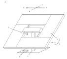
図1に本発明のヘリオスタット装置の一例を示す。図1において、手前から奥の方向が東西方向であり、左右方向が南北方向である。
なお、ここでは太陽電池パネルを備えた例を示すが、太陽電池パネルの代わりに反射鏡を備えたものとすることもできる。
図1に示すように、ヘリオスタット装置1は、全体として、発電パネル2とジャイロ機構3と支柱4とを備えている。ここでは発電パネル2は西側に傾いている。
Hereinafter, the present invention will be described in detail as an example of an embodiment with reference to the drawings, but the present invention is not limited thereto.
FIG. 1 shows an example of the heliostat device of the present invention. In FIG. 1, the direction from the front to the back is the east-west direction, and the left-right direction is the north-south direction.
In addition, although the example provided with the solar cell panel is shown here, it may be provided with a reflecting mirror instead of the solar cell panel.
As shown in FIG. 1, the
発電パネル2は太陽電池パネル5とフレーム6とからなっている。ここでは太陽電池パネル5は長方形のものが4枚備えられているが、1枚以上であればよく、数、大きさ、形状は特に限定されない。これら4枚の太陽電池パネルは1つのフレーム6により支持されている。フレーム6の形状、材質等はその都度、適宜決定することができる。太陽電池パネル5を支持し、風等を受けても変形しない程度の強度を有するものであれば良い。
The
また、発電パネル2自体の形状も特に限定されない。図1では、発電パネル2の全体としてロの字型になっている。すなわち、1つのフレーム6上に、中央部分を空けるようにして4枚の太陽電池パネル5をロの字型に配置している。このように配置することで、風が吹いていても発電パネル2の中央部分から風が吹き抜けていき、発電パネル2が揺れたり、強風で倒れたりするのを効果的に防ぐことができる。
Further, the shape of the
支柱4は、発電パネル2およびジャイロ機構3を支持できるものであればよく、太さ、長さ等は特に限定されない。発電パネル2等の大きさにより応じて適切なものを用意すればよい。
The
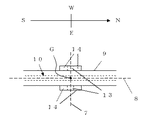
次にジャイロ機構3について説明する。図2、3にジャイロ機構の一例を示す。図2は図1のヘリオスタット装置1を背面側(東側)から見た側面図である。なお、発電パネル2が水平の状態である。また、図3はジャイロ機構の筒体付近の平面図である。
図2、3に示すように、ジャイロ機構3はフレーム6と連結しており、フレーム6(また、発電パネル2)を南北方向に回転させるための東西方向を軸方向とする仰角回転軸7と、東西方向に回転させるための南北方向を軸方向とする方位角回転軸8とを有している。これらの仰角回転軸7と方位角回転軸8は直交している。さらには、これらの直交する交点と、ジャイロ機構3に支えられた発電パネル2の重心Gとが一致している。
従来のような経緯台式はジャイロ型でもなく、当然、ジャイロの中心と重心Gが一致しているわけでなく、発電パネルを回転させるのに相当の力が必要であった。しかしながら、本発明のような上記の構成であれば、発電パネル2を従来よりも格段に小さな力で簡単に回転させることができ、少ない電力で太陽電池パネル5の角度調整を行うことができる。
Next, the
As shown in FIGS. 2 and 3, the
The conventional pedestal table is not a gyro type, and naturally, the center of the gyro and the center of gravity G do not coincide with each other, and a considerable force is required to rotate the power generation panel. However, with the above configuration as in the present invention, the
以下、ジャイロ機構3の、より具体的な構成について説明する。
長手方向が方位角回転軸8に沿うように配置されている筒体9を備えている。また、該筒体9を長手方向に貫通しており、方位角回転軸8上に位置する方位角回転シャフト10を備えている。さらには、その貫通している方位角回転シャフト10の両端同士を連結する連結カバー11が設けられており、該連結カバー11の先端には、フレーム6と連結する連結アーム12が設けられている。
なお、方位角回転シャフト10と連結カバー11の連結部分については、方位角回転シャフト10を回転軸として連結カバー11が東西方向に回転できるようになっていれば良い。例えば、両者は互いに溶接等されていて完全につながっており、方位角回転シャフト10自身の軸回転に伴い、連結カバー11も回転するような態様とすることができる。
Hereinafter, a more specific configuration of the
A
In addition, about the connection part of the
また、筒体9としては、その外形が角柱形状であっても良いし、円柱形状であっても良い。その内部を方位角回転シャフト10が貫通できるものであれば良い。
連結カバー11は、ここではコの字形状になっており、1つの天板15と該天板15を挟むように接合された2つの側板16とからなっている。筒体9を貫通した方位角シャフト10の両端に側板16がそれぞれ連結されている。なお、発電パネル2が水平の状態になっている場合、筒型9の上方に天板15が位置するようになっている。
そして、側板16の、天板15と接合している側とは反対の側には連結アーム12が連結されており、また上述したように該連結アーム12にフレーム6が連結されている。このような構成によって、筒体9、方位角回転シャフト10、連結カバー11、連結アーム12、フレーム6が一体化している。
Further, the outer shape of the
Here, the connecting cover 11 has a U-shape, and includes a
The connecting arm 12 is connected to the
さらには、筒体9の短手方向に突き出ており、仰角回転軸7上に位置する一対の仰角回転シャフト13を備えている。
これに対して支柱4には軸受14が設けられており、該軸受14によって、上記一対の仰角回転シャフト13が軸回転可能に支持されている。
Furthermore, it is provided with a pair of
On the other hand, the
そして上述したように、方位角回転シャフト10を回転軸として連結カバー11を東西方向に回転させることができ、該連結カバー11は連結アーム12を介してフレーム6、さらには太陽電池パネル5と連結しているので、それらを一体的に回転させることができる。すなわち、発電パネル2を東西方向に回転させることができ、その太陽電池パネル5のパネル面の東西方向の角度を調整することができる。
As described above, the connection cover 11 can be rotated in the east-west direction with the
一方、支柱4の軸受14上で、仰角回転シャフト13を回転軸として筒体9を南北方向に回転させることができ、該筒体9は、それを貫通する方位角回転シャフト10、連結カバー11、連結アーム12を介してフレーム6、さらには太陽電池パネル5と連結しているので、それらを一体的に回転させることができる。すなわち、発電パネル2を南北方向に回転させることができ、その太陽電池パネル5のパネル面の南北方向の角度を調整することができる。
On the other hand, on the bearing 14 of the
ジャイロ機構3のこのような構成によって発電パネル2を支柱4上で簡便に東西方向および南北方向に自在に回転させることができ、太陽電池パネル5のパネル面の角度を自由度高く調整することができる。このようなジャイロ型のものであれば、従来の経緯台式のものよりも太陽電池パネル5のパネル面の角度を自由に調整することができ、影の干渉の発生をより一層防ぐことができる。
With such a configuration of the
例えば、図1の発電パネルを備えた本発明と、同形状の発電パネルを備えた図8のような従来の経緯台式のものを考える。
従来装置では、発電パネルについて南北方向に角度を調整後、東西方向の角度調整は、実際には水平にしか回転できない。すなわち、発電パネルの下辺(および上辺)は常に地面に平行になるようにしか回転できない(下辺の両端の高さ位置が常に同じ)。
一方、上記のようなジャイロ機構を備えた本発明では、南北方向に角度を調整後、発電パネル全体を東西方向に回転可能である。すなわち、発電パネルの下辺(および上辺)の両端の高さ位置が互いに異なるように回転調整できるし、それらの高さ位置が同じになるように回転調整することもできる。
For example, consider the present invention having the power generation panel of FIG. 1 and the conventional graduation table type as shown in FIG. 8 having the same shape of the power generation panel.
In the conventional device, after adjusting the angle of the power generation panel in the north-south direction, the angle adjustment in the east-west direction can actually rotate only horizontally. That is, the lower side (and the upper side) of the power generation panel can only rotate so as to be always parallel to the ground (the height positions at both ends of the lower side are always the same).
On the other hand, in the present invention provided with the gyro mechanism as described above, the entire power generation panel can be rotated in the east-west direction after adjusting the angle in the north-south direction. That is, rotation adjustment can be performed so that the height positions of both ends of the lower side (and upper side) of the power generation panel are different from each other, and rotation adjustment can be performed so that the height positions are the same.
このように、太陽追尾型といっても、本発明のほうが従来の経緯台式のものよりも自由度高く発電パネルの角度調整を行うことができる。したがって、従来では影の干渉が起きてしまっていたようなヘリオスタット装置同士の間隔でも、本発明であれば角度の調整次第で影の干渉の発生を防止することができる。すなわち、ヘリオスタット装置同士をより近接して配置することもでき、単位土地面積あたりの発電効率を向上させることができる。 As described above, even if the solar tracking type is used, the present invention can adjust the angle of the power generation panel with a higher degree of freedom than the conventional graduation table type. Therefore, even if the distance between the heliostat devices has conventionally caused shadow interference, the present invention can prevent the occurrence of shadow interference depending on the angle adjustment. That is, heliostat devices can be arranged closer to each other, and the power generation efficiency per unit land area can be improved.
また、ジャイロ機構3は、仰角調整アクチュエータ17、方位角調整アクチュエータ18をさらに備えている。上記のようなジャイロ機構3において発電パネル2を回転させる手段は特に限定されないが、アクチュエータであれば簡便にモータ駆動で回転操作を行うことができる。
The
仰角調整アクチュエータ17の配置位置として、図2のように示す位置が挙げられる。支柱4と筒体9の下面側とを結ぶように取り付けられている。モータ駆動によって、仰角調整アクチュエータ17のアーム19が伸びることによって、筒体9の南側を押し、発電パネル2を北側へ回転させることができる。一方、アーム19が縮むことによって、筒体9の南側が引っ張られ、発電パネル2を南側へ回転させることができる。
As an arrangement position of the elevation angle adjusting actuator 17, a position shown in FIG. The
図4に方位角調整アクチュエータ18の配置位置の一例を示す。図4は方位角調整アクチュエータ18を北側から見た概略図である。
連結カバー11から東側に突き出た部分と、筒体9の下面から突き出た部分とを結ぶように、方位角調整アクチュエータ18が取り付けられている。モータ駆動によって、方位角調整アクチュエータ18のアーム20が伸びることによって、連結カバー11が西側に傾き、発電パネル2を西側へ回転させることができる。図5に、図4の状態から西側へ回転させたときの状態を示す。一方、アーム20が縮むことによって、連結カバー11が東側に傾き、発電パネル2を東側へ回転させることができる。
当然、これらとは別の位置に配置することも可能であるが、図2、4、5のような配置にすることによって、トラス構造がとられているので、耐風性を持つことができる。東西方向、南北方向とも共に、必要とする最大傾斜角に応じて、その角度が得られるように適切に各アクチュエータを配設することができる。
FIG. 4 shows an example of the arrangement position of the azimuth
An azimuth
Of course, it is possible to arrange them at positions other than these, but by arranging them as shown in FIGS. In both the east-west direction and the north-south direction, each actuator can be appropriately arranged so as to obtain the required maximum inclination angle.
また、図1に示すように、蓄電池21を配置しておき、これらのアクチュエータのモータを駆動させて、ジャイロ機構3を作動させるための電力を供給することもできる。
本発明は、前述したようにジャイロの中心と発電パネル2の重心が一致しているため、極めて小さい力で発電パネル2の回転制御を行うことができる。したがって、発電パネル2の回転駆動に要する消費電力を抑えることができる。このため、従来装置のように、外部からの電力供給のために大規模な配線を引くことなく、各ヘリオスタット装置に備えられた蓄電池21によって十分にジャイロ機構3を作動させて、発電パネル2を回転させ、太陽電池パネル5のパネル面の角度調整を行うことが可能である。電力供給の面において、自立したものとなる。
配線の設置に要するコスト、メンテナンスを省略することができ、簡便である。
Moreover, as shown in FIG. 1, the
In the present invention, since the center of the gyro and the center of gravity of the
The cost and maintenance required for installing the wiring can be omitted, which is simple.
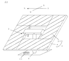
図6に、別の態様のヘリオスタット装置の一例を示す。この態様では、補助太陽電池パネル22をさらに備えている。ここでは、連結カバー11の上に配置されている。この補助太陽電池パネル22によって得られた電力を蓄電池21に蓄えることができるようになっている。このため、より一層確実に自立したものとすることができる。
なお、補助太陽電池パネル22の配置場所、大きさ等は特に限定されず、蓄電池21を充電するのに十分なものであれば良い。
In FIG. 6, an example of the heliostat apparatus of another aspect is shown. In this embodiment, an auxiliary
In addition, the arrangement | positioning location, magnitude | size, etc. of the auxiliary
太陽光発電装置において、太陽電池パネル(または発電パネル)が固定型のもの、ヘリオスタット装置を備え太陽追尾型で経緯台式のもの、本発明のヘリオスタット装置で、得られる太陽光エネルギーと装置の設置に要する面積について考察する。
固定型で得られる太陽光エネルギーを1とすると、経緯台式の装置、本発明の装置のような太陽追尾型のものでは、太陽の動きに対してパネル面を追従させることができるので1.6−1.7もの太陽光エネルギーを得ることができる。
In a solar power generation device, a solar cell panel (or power generation panel) is a fixed type, a solar tracking type with a heliostat device and a graduation type, and solar energy obtained by the heliostat device according to the present invention. Consider the area required for installation.
Assuming that the solar energy obtained by the fixed type is 1, in the solar tracking type device such as the graduation table type device or the device of the present invention, the panel surface can follow the movement of the sun. -1.7 solar energy can be obtained.
また、固定型で太陽電池パネルを設置するのに必要な面積を1とすると、アクセス道路として0.3の面積が必要と考えられる。すなわち、固定型は1.3の面積が必要となる。経緯台式の装置では、上述した1.6−1.7の太陽光エネルギーを得るためには1.6の面積が必要とされる。影の干渉を防ぐために固定型よりも広い面積が必要となる。
一方で本発明では、上述したように経緯台式の装置よりも各ヘリオスタット装置を近接して配置することができ、全体として、必要な面積は固定型と同程度、すなわち1.3程度とすることができる。
Further, assuming that the area required for installing the solar cell panel in a fixed type is 1, it is considered that an area of 0.3 is necessary as an access road. That is, the fixed mold requires an area of 1.3. In the scale table type device, an area of 1.6 is required to obtain the above-described solar energy of 1.6 to 1.7. In order to prevent shadow interference, a larger area than the fixed type is required.
On the other hand, in the present invention, as described above, each heliostat device can be arranged closer to the graduation table type device, and as a whole, the required area is about the same as the fixed type, that is, about 1.3. be able to.
このように、本発明のヘリオスタット装置は、固定型と同程度の設置面積で済ますことができ、かつ、経緯台式の装置と同程度の太陽光エネルギーを得ることができる。このため、従来よりも発電効率を向上させることができる。
しかも、ジャイロの中心と発電パネルの重心とが一致しており、回転制御を極めて小さい力で簡単に行うことができる。
As described above, the heliostat device of the present invention can be installed with the same installation area as that of the fixed type, and can obtain solar energy of the same level as that of the graduation device. For this reason, power generation efficiency can be improved compared with the past.
Moreover, since the center of the gyro and the center of gravity of the power generation panel coincide with each other, rotation control can be easily performed with extremely small force.
以上、太陽電池パネルを備えた場合について説明してきたが、太陽電池パネルの代わりに反射鏡を配設することもできる。
図7に、反射鏡を配設したヘリオスタット装置の一例を示す。図7のヘリオスタット装置23では4枚の長方形の反射鏡24が配設されている。その他の構成、例えば、フレームやジャイロ機構、支柱等の構成は同様のものとすることができる。そして、同様に、反射鏡24を東西方向や南北方向に自在に回転させ、その反射面の角度を適宜調整することが可能である。さらには、回転に必要な力が小さいこと、回転制御の自由度が高いこと、影の干渉の発生を従来よりも抑制できること等、実質的に、同様の効果を有することができる。
As described above, the case where the solar cell panel is provided has been described, but a reflecting mirror may be provided instead of the solar cell panel.
FIG. 7 shows an example of a heliostat device provided with a reflecting mirror. In the
なお、本発明は、上記実施形態に限定されるものではない。上記実施形態は、例示であり、本発明の特許請求の範囲に記載された技術的思想と実質的に同一な構成を有し、同様な作用効果を奏するものは、いかなるものであっても本発明の技術的範囲に包含される。 The present invention is not limited to the above embodiment. The above-described embodiment is an exemplification, and the present invention has substantially the same configuration as the technical idea described in the claims of the present invention, and any device that exhibits the same function and effect is the present invention. It is included in the technical scope of the invention.
1、23…本発明のヘリオスタット装置、 2…発電パネル、 3…ジャイロ機構、
4…支柱、 5…太陽電池パネル、 6…フレーム、 7…仰角回転軸、
8…方位角回転軸、 9…筒体、 10…方位角回転シャフト、
11…連結カバー、 12…連結アーム、 13…仰角回転シャフト、
14…軸受、 15…天板、 16…側板、 17…仰角調整アクチュエータ、
18…方位角調整アクチュエータ、 19…仰角調整アクチュエータのアーム、
20…方位角調整アクチュエータのアーム、 21…蓄電池、
22…補助太陽電池パネル、24…反射鏡、 G…発電パネルの重心。
1, 23 ... Heliostat device of the present invention, 2 ... Power generation panel, 3 ... Gyro mechanism,
4 ... post, 5 ... solar panel, 6 ... frame, 7 ... elevation rotation axis,
8 ... Azimuth rotation axis, 9 ... Cylinder, 10 ... Azimuth rotation shaft,
11 ... Connection cover, 12 ... Connection arm, 13 ... Elevation angle rotation shaft,
14 ... Bearing, 15 ... Top plate, 16 ... Side plate, 17 ... Elevation angle adjustment actuator,
18 ... Azimuth angle adjusting actuator, 19 ... Elevation angle adjusting actuator arm,
20 ... Arm of azimuth angle adjusting actuator, 21 ... Storage battery,
22 ... Auxiliary solar cell panel, 24 ... Reflector, G ... Center of gravity of power generation panel.
Claims (6)
前記反射鏡または前記太陽電池パネルを支持するフレームと、
該フレームを南北方向に回転させるための東西方向を軸方向とする仰角回転軸、及び前記フレームを東西方向に回転させるための南北方向を軸方向とする方位角回転軸を有し、前記仰角回転軸と前記方位角回転軸とが直交するジャイロ機構と、
該ジャイロ機構を介して前記フレームを支持する支柱とを備えており、
前記仰角回転軸を回転軸として、前記フレームと、前記反射鏡または前記太陽電池パネルとが一体的に南北方向に回転されることで、前記フレームに支持された反射鏡の反射面または太陽電池パネルのパネル面の南北方向の角度が調整されるものであり、
前記方位角回転軸を回転軸として、前記フレームと、前記反射鏡または前記太陽電池パネルとが一体的に東西方向に回転されることで、前記フレームに支持された反射鏡の反射面または太陽電池パネルのパネル面の東西方向の角度が調整されるものであり、
前記フレームと、該フレームに支持された前記反射鏡または前記太陽電池パネルとからなる発電パネルの重心が、前記ジャイロ機構の前記仰角回転軸と前記方位角回転軸とが直交する交点に一致しているものであることを特徴とするヘリオスタット装置。 A heliostat device comprising one or more reflecting mirrors or solar cell panels that reflect sunlight, and adjusting the angle of the reflecting surface of the reflecting mirror or the panel surface of the solar cell panel to follow the movement of the sun,
A frame that supports the reflecting mirror or the solar cell panel;
An elevation angle rotation axis having the east-west direction as an axial direction for rotating the frame in the north-south direction, and an azimuth rotation axis having the north-south direction as an axial direction for rotating the frame in the east-west direction, the elevation rotation A gyro mechanism in which an axis and the azimuth rotation axis are orthogonal to each other;
A support for supporting the frame via the gyro mechanism,
The frame and the reflecting mirror or the solar cell panel are integrally rotated in the north-south direction around the elevation angle rotation axis as a rotation axis, so that the reflecting surface of the reflecting mirror supported by the frame or the solar cell panel The angle of the north-south direction of the panel surface is adjusted,
With the azimuth rotation axis as the rotation axis, the frame and the reflecting mirror or the solar cell panel are integrally rotated in the east-west direction so that the reflecting surface of the reflecting mirror or the solar cell supported by the frame The east-west angle of the panel surface of the panel is adjusted,
The center of gravity of the power generation panel comprising the frame and the reflecting mirror or the solar cell panel supported by the frame coincides with the intersection where the elevation rotation axis and the azimuth rotation axis of the gyro mechanism are orthogonal to each other. A heliostat device characterized by that.
長手方向が前記方位角回転軸に沿うように配置されている筒体と、
該筒体を長手方向に貫通しており、前記方位角回転軸上に位置する方位角回転シャフトと、
該貫通している方位角回転シャフトの両端同士を連結する連結カバーと、
該連結カバーと前記フレームを連結する連結アームと、
前記筒体から短手方向に突き出ており、前記仰角回転軸上に位置する一対の仰角回転シャフトとを備えており、
前記支柱は、前記一対の仰角回転シャフトを軸回転可能に支持する軸受を備えており、
前記方位角回転軸上の前記方位角回転シャフトを回転軸として、前記連結カバーと前記連結アームと前記フレームとが一体的に東西方向に回転可能であり、
前記支柱の軸受上で、前記仰角回転軸上の前記一対の仰角回転シャフトを回転軸として、前記筒体と前記方位角回転シャフトと前記連結カバーと前記連結アームと前記フレームとが一体的に南北方向に回転可能なものであることを特徴とする請求項1に記載のヘリオスタット装置。 The gyro mechanism is
A cylindrical body arranged such that the longitudinal direction is along the azimuth rotation axis;
An azimuth rotary shaft that passes through the cylinder in the longitudinal direction and is located on the azimuth rotary axis;
A connecting cover that connects both ends of the penetrating azimuth rotating shaft;
A connecting arm that connects the connecting cover and the frame;
Projecting from the cylindrical body in the short direction, and comprising a pair of elevation rotation shafts positioned on the elevation rotation shaft,
The support column includes a bearing that supports the pair of elevation rotation shafts so as to be axially rotatable.
With the azimuth rotation shaft on the azimuth rotation axis as the rotation axis, the connection cover, the connection arm, and the frame can be integrally rotated in the east-west direction,
The cylindrical body, the azimuth rotation shaft, the connection cover, the connection arm, and the frame are integrally north and south with the pair of elevation rotation shafts on the elevation rotation shaft as a rotation axis on the bearing of the support column. The heliostat device according to claim 1, wherein the heliostat device is rotatable in a direction.
Priority Applications (5)
| Application Number | Priority Date | Filing Date | Title |
|---|---|---|---|
| JP2016125265A JP2017227408A (en) | 2016-06-24 | 2016-06-24 | Heliostat device |
| US16/312,767 US20190165721A1 (en) | 2016-06-24 | 2017-06-22 | Heliostat apparatus and solar power generating method |
| EP17815492.8A EP3477219A4 (en) | 2016-06-24 | 2017-06-22 | Heliostat apparatus and solar power generation method |
| CN201780039136.5A CN109690208A (en) | 2016-06-24 | 2017-06-22 | Heliostat device and method for electric generation using solar energy |
| PCT/JP2017/023091 WO2017222026A1 (en) | 2016-06-24 | 2017-06-22 | Heliostat apparatus and solar power generation method |
Applications Claiming Priority (1)
| Application Number | Priority Date | Filing Date | Title |
|---|---|---|---|
| JP2016125265A JP2017227408A (en) | 2016-06-24 | 2016-06-24 | Heliostat device |
Publications (1)
| Publication Number | Publication Date |
|---|---|
| JP2017227408A true JP2017227408A (en) | 2017-12-28 |
Family
ID=60891512
Family Applications (1)
| Application Number | Title | Priority Date | Filing Date |
|---|---|---|---|
| JP2016125265A Pending JP2017227408A (en) | 2016-06-24 | 2016-06-24 | Heliostat device |
Country Status (1)
| Country | Link |
|---|---|
| JP (1) | JP2017227408A (en) |
Cited By (1)
| Publication number | Priority date | Publication date | Assignee | Title |
|---|---|---|---|---|
| WO2019230150A1 (en) | 2018-05-31 | 2019-12-05 | 株式会社SolarFlame | Heliostat device |
Citations (11)
| Publication number | Priority date | Publication date | Assignee | Title |
|---|---|---|---|---|
| US4586488A (en) * | 1983-12-15 | 1986-05-06 | Noto Vincent H | Reflective solar tracking system |
| JP2004235284A (en) * | 2003-01-29 | 2004-08-19 | Daido Steel Co Ltd | Method of installing solar cell panel for condensating solar power generation device |
| DE102008023549A1 (en) * | 2008-05-14 | 2009-11-19 | Dieckmann, Klaus E., Dipl.-Ing. | Gimbal-mounted process surface for solar-tracking photovoltaic system, has solar panel provided with solar modules and fastened to support, which is rotatably fastened around two axes by universal joint |
| JP3158018U (en) * | 2009-12-08 | 2010-03-11 | 干布太陽能股▲ふん▼有限公司 | Solar energy solar tracking device structure |
| JP2010205762A (en) * | 2009-02-27 | 2010-09-16 | Mitsubishi Electric Corp | Tracking type photovoltaic power generation device |
| JP2011066030A (en) * | 2009-09-15 | 2011-03-31 | Mitsubishi Electric Corp | Tracking type photovoltaic system |
| WO2013129177A1 (en) * | 2012-02-29 | 2013-09-06 | 三菱重工業株式会社 | Optical condenser, and heat collection apparatus and solar thermal power generation apparatus equipped therewith |
| JP2013225650A (en) * | 2012-04-23 | 2013-10-31 | Topper Sun Energy Technology Co Ltd | Automatic sun adjustment control device for solar power generator unit |
| WO2014071683A1 (en) * | 2012-11-06 | 2014-05-15 | Liu Jianzhong | Double-shaft tracking support |
| JP2014527794A (en) * | 2011-08-15 | 2014-10-16 | モーガン ソーラー インコーポレーテッド | Self-stabilizing solar tracking device |
| WO2015037230A1 (en) * | 2013-09-10 | 2015-03-19 | 株式会社SolarFlame | Heliostat device, solar thermal collection device, and solar concentrating photovoltaic device |
-
2016
- 2016-06-24 JP JP2016125265A patent/JP2017227408A/en active Pending
Patent Citations (11)
| Publication number | Priority date | Publication date | Assignee | Title |
|---|---|---|---|---|
| US4586488A (en) * | 1983-12-15 | 1986-05-06 | Noto Vincent H | Reflective solar tracking system |
| JP2004235284A (en) * | 2003-01-29 | 2004-08-19 | Daido Steel Co Ltd | Method of installing solar cell panel for condensating solar power generation device |
| DE102008023549A1 (en) * | 2008-05-14 | 2009-11-19 | Dieckmann, Klaus E., Dipl.-Ing. | Gimbal-mounted process surface for solar-tracking photovoltaic system, has solar panel provided with solar modules and fastened to support, which is rotatably fastened around two axes by universal joint |
| JP2010205762A (en) * | 2009-02-27 | 2010-09-16 | Mitsubishi Electric Corp | Tracking type photovoltaic power generation device |
| JP2011066030A (en) * | 2009-09-15 | 2011-03-31 | Mitsubishi Electric Corp | Tracking type photovoltaic system |
| JP3158018U (en) * | 2009-12-08 | 2010-03-11 | 干布太陽能股▲ふん▼有限公司 | Solar energy solar tracking device structure |
| JP2014527794A (en) * | 2011-08-15 | 2014-10-16 | モーガン ソーラー インコーポレーテッド | Self-stabilizing solar tracking device |
| WO2013129177A1 (en) * | 2012-02-29 | 2013-09-06 | 三菱重工業株式会社 | Optical condenser, and heat collection apparatus and solar thermal power generation apparatus equipped therewith |
| JP2013225650A (en) * | 2012-04-23 | 2013-10-31 | Topper Sun Energy Technology Co Ltd | Automatic sun adjustment control device for solar power generator unit |
| WO2014071683A1 (en) * | 2012-11-06 | 2014-05-15 | Liu Jianzhong | Double-shaft tracking support |
| WO2015037230A1 (en) * | 2013-09-10 | 2015-03-19 | 株式会社SolarFlame | Heliostat device, solar thermal collection device, and solar concentrating photovoltaic device |
Cited By (2)
| Publication number | Priority date | Publication date | Assignee | Title |
|---|---|---|---|---|
| WO2019230150A1 (en) | 2018-05-31 | 2019-12-05 | 株式会社SolarFlame | Heliostat device |
| US11387773B2 (en) | 2018-05-31 | 2022-07-12 | Tressbio Laboratory Co., Ltd. | Heliostat apparatus |
Similar Documents
| Publication | Publication Date | Title |
|---|---|---|
| US7705277B2 (en) | Sun tracking solar panels | |
| US7884308B1 (en) | Solar-powered sun tracker | |
| CN103558860B (en) | A kind of photovoltaic generation sunlight following device | |
| WO2015037230A1 (en) | Heliostat device, solar thermal collection device, and solar concentrating photovoltaic device | |
| JP2019047623A (en) | Photovoltaic power generation method | |
| KR101005296B1 (en) | Solar power plant using sound proof wall of road | |
| KR100760043B1 (en) | Solar power plant having angle adjustment device | |
| JP2013513817A (en) | A heliostat that controls the direction of reflection with a sensor | |
| CN204906253U (en) | Track reflective album of solar electric system | |
| JP2010205762A (en) | Tracking type photovoltaic power generation device | |
| JP2010205764A (en) | Tracking type photovoltaic power generation device | |
| WO2017222026A1 (en) | Heliostat apparatus and solar power generation method | |
| JP6342632B2 (en) | Solar concentrator | |
| CN207963198U (en) | Heliostat and tower-type solar thermal power generating system | |
| CN101388625A (en) | Solar concentration electricity generating apparatus | |
| CN205490358U (en) | Photovoltaic is multi freedom stand for support | |
| JP2017227408A (en) | Heliostat device | |
| JP2013172145A (en) | Tracking type photovoltaic power generation device | |
| JP2013162038A (en) | Concentrating photovoltaic power generation system | |
| JP2017229195A (en) | Photovoltaic power generation method | |
| CN203070103U (en) | Simplified biaxial linkage-type solar photovoltaic power generation system | |
| JP6535402B1 (en) | Sun tracking device | |
| KR101647566B1 (en) | Sun location tracking type solar generation | |
| KR100767704B1 (en) | A solar power generating system having solar tracker | |
| KR101585002B1 (en) | Solar tracking system using the electric power difference between solar cells |
Legal Events
| Date | Code | Title | Description |
|---|---|---|---|
| A711 | Notification of change in applicant |
Free format text: JAPANESE INTERMEDIATE CODE: A711 Effective date: 20180719 |
|
| A521 | Request for written amendment filed |
Free format text: JAPANESE INTERMEDIATE CODE: A821 Effective date: 20180719 |
|
| A621 | Written request for application examination |
Free format text: JAPANESE INTERMEDIATE CODE: A621 Effective date: 20190617 |
|
| A131 | Notification of reasons for refusal |
Free format text: JAPANESE INTERMEDIATE CODE: A131 Effective date: 20200331 |
|
| A601 | Written request for extension of time |
Free format text: JAPANESE INTERMEDIATE CODE: A601 Effective date: 20200521 |
|
| A02 | Decision of refusal |
Free format text: JAPANESE INTERMEDIATE CODE: A02 Effective date: 20201027 |