JP2016127628A - Coreless coil and manufacturing method for the same, and permanent magnet type rotary machine and manufacturing method for the same - Google Patents

Coreless coil and manufacturing method for the same, and permanent magnet type rotary machine and manufacturing method for the same Download PDF

Info

Publication number
JP2016127628A
JP2016127628A JP2014264497A JP2014264497A JP2016127628A JP 2016127628 A JP2016127628 A JP 2016127628A JP 2014264497 A JP2014264497 A JP 2014264497A JP 2014264497 A JP2014264497 A JP 2014264497A JP 2016127628 A JP2016127628 A JP 2016127628A
Authority
JP
Japan
Prior art keywords
coil
magnetic flux
flux linkage
separate
pole side
Prior art date
Legal status (The legal status is an assumption and is not a legal conclusion. Google has not performed a legal analysis and makes no representation as to the accuracy of the status listed.)
Pending
Application number
JP2014264497A
Other languages
Japanese (ja)
Inventor
公明 岩谷
Masaaki Iwatani
公明 岩谷
ゆき 懸田
Yuki Kakeda
ゆき 懸田
Current Assignee (The listed assignees may be inaccurate. Google has not performed a legal analysis and makes no representation or warranty as to the accuracy of the list.)
Individual
Original Assignee
Individual
Priority date (The priority date is an assumption and is not a legal conclusion. Google has not performed a legal analysis and makes no representation as to the accuracy of the date listed.)
Filing date
Publication date
Application filed by Individual filed Critical Individual
Priority to JP2014264497A priority Critical patent/JP2016127628A/en
Publication of JP2016127628A publication Critical patent/JP2016127628A/en
Pending legal-status Critical Current

Links

Images

Landscapes

  • Dc Machiner (AREA)
  • Windings For Motors And Generators (AREA)
  • Insulation, Fastening Of Motor, Generator Windings (AREA)
  • Manufacture Of Motors, Generators (AREA)

Abstract

PROBLEM TO BE SOLVED: To provide a coreless coil having an axial plane U-shape that can surround one permanent magnet constituting field magnetic flux or magnet yoke, and provide a permanent magnet type rotary machine that is small in size and light in weight and can achieve high output and high efficiency.SOLUTION: An axial plane U-shaped coil is constructed by plural separate coils 2 which are at least dual-partitioned in the peripheral direction and also divided at a mechanical angle of 180° or less. Each separate coil 2 has a magnetic flux interlinkage part 3N corresponding to the N-pole side of a permanent magnet, a magnetic flux interlinking part 3S' corresponding to the S-pole side of the permanent magnet and a crossover part 4 for linking the conductors of the N-pole side magnetic flux interlinking part 3N and the S-pole side magnetic flux interlinking part 3S. The plural separate coils 2 are joined to one another in the peripheral direction to configure the axial plane U-shaped coil.SELECTED DRAWING: Figure 1

Description

本発明は、モータや発電機等に組込まれるコアレスコイル及びその製造方法並びにそれを用いた永久磁石型回転機とその製造方法に関するものである。更に詳述すると、本発明はラジアル型あるいはアキシャル型の永久磁石型回転機のステータコイルあるいはロータコイルとして有用なコアレスコイル及び製造方法並びにそれを用いた永久磁石型回転機とその製造方法に関するものである。   The present invention relates to a coreless coil incorporated in a motor, a generator or the like, a manufacturing method thereof, a permanent magnet type rotating machine using the same, and a manufacturing method thereof. More specifically, the present invention relates to a coreless coil useful as a stator coil or a rotor coil of a radial type or axial type permanent magnet type rotating machine, a manufacturing method thereof, a permanent magnet type rotating machine using the same, and a manufacturing method thereof. is there.

コアレスコイルは、例えば、ロータコイルあるいはステータコイルとしてラジアル方向(径方向)に対向させて配置された外側の永久磁石と内側の永久磁石との間(磁気ギャップ部)に挿入され、永久磁石とコアレスコイルとをラジアル方向に僅かなギャップを隔てて対向するように組み込まれて永久磁石ラジアル型回転機(電動機又は発電機)を構成することが知られている。このコアレスコイルは、ステータコイルとして用いられる場合でも、あるいはロータコイルとして用いられる場合でも、その内方に磁気回路(永久磁石あるいは界磁ヨーク)を収容するために、筒形あるいはカップ形に形成されており、ロータシャフトあるいは発電機ケース本体などに片持ちで支持されている。尚、本明細書においては、対向させて配置されている一対の永久磁石の間のギャップ(磁気的空隙)に配置されている導体領域(トルク発生あるいは発電に寄与する有効コイル領域)を磁束鎖交部と呼び、ギャップの外に配置されて永久磁石と重ならない導体領域(トルク発生あるいは発電に寄与しないコイル端領域)を渡り線部と呼ぶ。   The coreless coil is inserted, for example, between the outer permanent magnet and the inner permanent magnet (magnetic gap portion) arranged in the radial direction (radial direction) as a rotor coil or a stator coil. It is known that a permanent magnet radial type rotary machine (electric motor or generator) is configured by incorporating a coil in a radial direction so as to face each other with a slight gap. Whether used as a stator coil or a rotor coil, this coreless coil is formed in a cylindrical shape or a cup shape in order to accommodate a magnetic circuit (permanent magnet or field yoke) inside. And cantilevered on the rotor shaft or generator case body. In this specification, a conductor region (effective coil region contributing to torque generation or power generation) arranged in a gap (magnetic gap) between a pair of permanent magnets arranged to face each other is defined as a magnetic flux chain. A conductor region (coil end region that does not contribute to torque generation or power generation) arranged outside the gap and not overlapping the permanent magnet is called a crossover portion.

従来の永久磁石ラジアル型回転機(電動機又は発電機)のコアレスコイルは、シリンダ形(あるいはカップ形)に構成してロータコイルあるいはステータコイルとしてギャップに挿入されるように組み込まれている。ここで、永久磁石ラジアル型回転機のコアレスコイルは、界磁を形成する内ロータ磁石と外ロータ磁石との間のギャップに挿入する構造を採用しているため、コイルの厚さは、少なくとも界磁と交差する巻線部分・磁束鎖交部においては界磁のギャップの寸法より小さく、かつ積層したコイルの厚さの一部でもギャップの大きさを越えないようにする必要がある。   A coreless coil of a conventional permanent magnet radial type rotating machine (an electric motor or a generator) is configured as a cylinder (or cup) and is incorporated so as to be inserted into a gap as a rotor coil or a stator coil. Here, the coreless coil of the permanent magnet radial type rotating machine employs a structure that is inserted into the gap between the inner rotor magnet and the outer rotor magnet forming the field, and therefore the thickness of the coil is at least the field thickness. It is necessary to make the winding portion and the magnetic flux linkage portion intersecting with the magnetism smaller than the size of the field gap and not to exceed the gap size even in a part of the thickness of the laminated coils.

このため、従来のコアレスコイルとしては、渡り線を必要としないスキュー巻きが採用されている。ところが、スキュー巻きは、コイルの回転方向に対し巻線が直角に位置しないことから、マイナスのトルクを生じることがあり、同一体積の理想的に巻いたコイルが発生するトルクより小さなトルクしか得られないという欠点がある。つまり、スキュー巻きは、コイル端領域での線の重複による耳状の渡り線部の形成を避けるという構造を採用した結果、効率の面で犠牲をはらう結果となっている。このことは、効率が悪くても組立の容易さを優先させる比較的小容量の回転電機であれば、問題ない。しかし、例えば電気自動車の駆動、制動用の回転電機のような用途においては、比較的大容量であるため効率の低いことは致命的な欠点となるからスキュー巻きは採用できない。   For this reason, skew winding that does not require a jumper is employed as a conventional coreless coil. However, skew winding can generate negative torque because the winding is not positioned at right angles to the direction of coil rotation, and only a smaller torque than that generated by an ideally wound coil of the same volume can be obtained. There is a disadvantage of not. In other words, skew winding results in a sacrifice in terms of efficiency as a result of employing a structure that avoids the formation of an ear-shaped crossover portion due to overlapping of wires in the coil end region. This is not a problem if the rotating electrical machine has a relatively small capacity that prioritizes ease of assembly even if the efficiency is low. However, in applications such as driving and braking electric rotating machines for electric vehicles, for example, skew winding cannot be adopted because of its relatively large capacity and low efficiency is a fatal defect.

他方、磁束鎖交部の巻線をロータシャフトに平行に巻き、両端に渡り線を設けるカップ状あるいはシリンダ状のコアレスコイルでは、線が重なり体積が増す両端の渡り線の部分が耳朶のように垂れ下がる耳部を形成するという問題を有している。そこで、耳部の厚さよりも広いギャップを採らなければ、予め組み立てられた内ロータ磁石と外ロータ磁石との間のギャップにコイルを組み込むことはできない。このため、ギャップが耳部の厚さよりも広がる(磁束鎖交部のコイルの厚さよりも遙かに広がる)ことで、鎖交磁束が減少してモータの効率が低下する問題がある。しかも、ラジアル方向のスペースも必要となりコアレス回転機の小型化を妨げる。また、鎖交磁束を増やすためギャップの広さを磁束鎖交部のコイルの厚みよりも僅かに広いものとすれば、ギャップより大きな寸法の渡り線の耳部が邪魔するため、ギャップを構成した状態即ち外側の永久磁石と内側の永久磁石(あるいはいずれか一方が永久磁石で他方が界磁ヨークの組み合わせ)とを組み立てた状態では、コアレスコイルを組み込むことできない。   On the other hand, in the case of a cup-shaped or cylinder-shaped coreless coil in which the winding of the magnetic flux linkage part is wound in parallel to the rotor shaft and the connecting wire is provided at both ends, the connecting wire portions at the both ends where the wires overlap and the volume increases are like earlobe It has the problem of forming a hanging ear. Therefore, if a gap wider than the thickness of the ear portion is not taken, a coil cannot be incorporated in the gap between the inner rotor magnet and the outer rotor magnet assembled in advance. For this reason, there is a problem in that the gap is larger than the thickness of the ear portion (much wider than the thickness of the coil at the magnetic flux linkage portion), so that the flux linkage is reduced and the efficiency of the motor is lowered. In addition, a radial space is also required, which prevents the coreless rotating machine from being downsized. In addition, if the width of the gap is slightly larger than the thickness of the coil at the magnetic flux linkage part in order to increase the interlinkage magnetic flux, the ear part of the crossover wire having a dimension larger than the gap interferes with the gap. In a state where the outer permanent magnet and the inner permanent magnet (or one of the permanent magnets and the other is a combination of field yokes) are assembled, the coreless coil cannot be incorporated.

そこで、カップ状コイルの界磁ギャップ部の巻線をロータシャフトに平行に巻き、両端の渡り線により構成される耳部の一方が界磁ギャップ部の寸法より小さく、他方が大きくなることを許容する構造とし、外側マグネットヨークの内側に永久磁石を固定した外側ヨーク組立体をロータに固定し、次にコイルを電機に装着して固定した後、内側ヨークを挿入してロータに固定して組み立てる回転電機の構造及び製造方法が提案されている(特許文献1)。これにより、コアレス型電動機等の回転電機において、界磁ギャップ部分の巻線部を軸と平行に配置し、かつ界磁ギャップ長より大きな寸法の渡り線耳部を形成しても、界磁ヨークを分割してコイル組み込み後に組み立てることを可能としている。   Therefore, the winding of the field gap portion of the cup-shaped coil is wound in parallel with the rotor shaft, and one of the ear portions constituted by the connecting wires at both ends is smaller than the size of the field gap portion and the other is allowed to be larger. The outer yoke assembly in which the permanent magnet is fixed to the inner side of the outer magnet yoke is fixed to the rotor, and then the coil is mounted and fixed to the electric machine, and then the inner yoke is inserted and fixed to the rotor for assembly. A structure and a manufacturing method of a rotating electrical machine have been proposed (Patent Document 1). As a result, in a rotating electrical machine such as a coreless type electric motor, even if the winding portion of the field gap portion is arranged in parallel with the axis and a crossover ear portion having a dimension larger than the field gap length is formed, It is possible to divide and assemble after incorporating the coil.

特開平6−70522号公報JP-A-6-70522

しかしながら、特許文献1記載のコアレス型回転機においても、コアレスコイルをカップ形あるいはシリンダ形にすることによって、コイル内に界磁束を構成する永久磁石あるいは界磁ヨークを軸方向から挿入可能とする構造であることには変わりなく、コアレスコイルを片持ちで支持することとなる。このため、コアレスコイルの機械的強度、機械的支持強度が不足することから、支持が安定しないという問題がある。   However, even in the coreless type rotating machine described in Patent Document 1, a structure in which a permanent magnet or a field yoke constituting a field magnetic flux can be inserted into the coil from the axial direction by making the coreless coil into a cup shape or a cylinder shape. The coreless coil is supported in a cantilever manner. For this reason, there is a problem that the support is not stable because the mechanical strength and mechanical support strength of the coreless coil are insufficient.

また、コアレスコイルは巻心が存在しないために、コア(積層鉄心)を巻心として導体を巻き付ける巻線作業に比べて加工し難く、太い導体を用いることが難しい。また、従来のコアレスコイルは、専用巻線機を使って導体を巻き上げ、その後に接着剤で固めて一体に成形しているので、コイル自体で必要な強度が得られない場合もあり、コイルとしての機械的強度が弱い。この観点からも太い導体が使えない。このため、従来のコアレスコイルは、通常0.1mm〜0.5mm前後、太くても0.8mm程度の直径の銅線しか使用できず、回転機の出力に限界があり、一般に150W程度の小型のモータしか実用化されていない。   Further, since the coreless coil does not have a winding core, it is difficult to process compared to a winding operation in which a conductor is wound around a core (laminated core), and it is difficult to use a thick conductor. In addition, the conventional coreless coil is made by winding up the conductor using a dedicated winding machine, and then solidifying it with an adhesive and integrally forming it, so the required strength may not be obtained with the coil itself. The mechanical strength of is weak. From this point of view, thick conductors cannot be used. For this reason, the conventional coreless coil can only use copper wire with a diameter of about 0.1 mm to about 0.5 mm, and a thickness of about 0.8 mm at most, and there is a limit to the output of the rotating machine. Only motors of this type have been put into practical use.

しかも、コアレスコイルが接着剤によって固められるため、放熱性が悪くなるという問題を有する。   And since a coreless coil is hardened with an adhesive agent, it has the problem that heat dissipation worsens.

また、永久磁石アキシャル型(面対向型)回転機の場合にも、薄型化を図るため、プリント基板にエッチングによりコイルを形成したディスク型コアレスコイルが用いられているが、ワイヤを巻いたものに比べて大出力が得られないという問題を有している。   Also, in the case of permanent magnet axial type (surface facing type) rotating machine, a disk type coreless coil in which a coil is formed by etching on a printed circuit board is used to reduce the thickness. Compared to this, there is a problem that a large output cannot be obtained.

また、従来の一般的なカップ型あるいはシリンダ型のコアレスコイルの場合には、渡り線部分がロータシャフトに対して平行に引き出されてコアレスコイル全長が軸方向へ長くなることから、小型化に制約を受ける問題がある。また、特許文献1記載の発明にかかるコアレスコイルにおいても、磁束鎖交部の導体の両端に膨らんだ耳部が径方向外側及び内側へはみ出るため、軸方向並びに外径方向の双方の寸法が大きくなり、回転機としての小型化に制約を受けることは同様である。   In addition, in the case of a conventional general cup type or cylinder type coreless coil, the connecting wire part is drawn out in parallel to the rotor shaft, and the entire length of the coreless coil becomes longer in the axial direction. There is a problem to receive. Also, in the coreless coil according to the invention described in Patent Document 1, since the ears swollen at both ends of the conductor of the magnetic flux linkage part protrude outwardly and inward in the radial direction, the dimensions in both the axial direction and the outer radial direction are large. Therefore, it is the same that the size reduction as a rotating machine is restricted.

さらに、専用巻線機の開発と設備投資を必要とする。   Furthermore, it requires the development of dedicated winding machines and capital investment.

本発明は、界磁束を構成する一方の永久磁石あるいは界磁ヨークを囲繞可能とする軸平面コ形のコアレスコイルとその製造方法並びにそれを用いる永久磁石型回転機とその製造方法を提供することを目的とする。また、本発明は、小型・軽量・高出力・高効率が可能な永久磁石型回転機及びその製造方法を提供することを目的とする。   The present invention provides an axial plane U-shaped coreless coil capable of surrounding one permanent magnet or field yoke constituting a field magnetic flux, a manufacturing method thereof, a permanent magnet type rotating machine using the same, and a manufacturing method thereof. With the goal. Another object of the present invention is to provide a permanent magnet type rotating machine that is small, light, high output, and high in efficiency, and a method for manufacturing the same.

かかる目的を達成するために請求項1記載のコアレスコイルは、周方向に少なくとも2分割され、機械角で180°以下に分割された複数のセパレートコイルによって構成され、各セパレートコイルは、永久磁石のN極側に対応する磁束鎖交部と、永久磁石のS極側に対応する磁束鎖交部と、N極側磁束鎖交部とS極側磁束鎖交部の導体を繋ぐ渡り線部とを有し、複数のセパレートコイルを周方向に連結することによって、軸平面形状コ形のコイルを構成するようにしている。   In order to achieve such an object, the coreless coil according to claim 1 is constituted by a plurality of separate coils which are divided at least in the circumferential direction and divided by a mechanical angle of 180 ° or less, and each separate coil is made of a permanent magnet. A magnetic flux linkage portion corresponding to the N pole side, a magnetic flux linkage portion corresponding to the S pole side of the permanent magnet, a crossover portion connecting the conductors of the N pole side magnetic flux linkage portion and the S pole side magnetic flux linkage portion, And by connecting a plurality of separate coils in the circumferential direction, an axial plane U-shaped coil is configured.

ここで、セパレートコイルは、周方向にずらして互いに入り込ませがら組み合わせる入れ子構造にすることが好ましい。     Here, it is preferable that the separate coils have a nested structure in which the separate coils are combined while being shifted in the circumferential direction.

また、セパレートコイルには、該コイルを構成する導体を内側から支持して固定するコイルケースを備えることが好ましい。   Further, the separate coil preferably includes a coil case that supports and fixes a conductor constituting the coil from the inside.

さらに、セパレートコイルは、内周側にロータシャフトが貫通する円弧部を有し、かつロータシャフトと平行に巻かれている外周縁部分の導体によってロータシャフトの径方向に形成される界磁束が通過する磁束鎖交部を構成し、渡り線部がロータシャフトと直交する面に沿って磁束鎖交部の導体の両端で径方向内側に折り曲げられかつ周方向に引き回されてロータシャフト周辺を迂回し、磁束鎖交部と渡り線部とが軸平面でコの字形を成すものであることが好ましい。   Further, the separate coil has an arc portion through which the rotor shaft passes on the inner peripheral side, and a field magnetic flux formed in the radial direction of the rotor shaft by a conductor at the outer peripheral edge wound in parallel with the rotor shaft passes. The crossover portion is bent radially inward at both ends of the conductor of the magnetic flux linkage along the plane orthogonal to the rotor shaft and is routed in the circumferential direction to bypass the periphery of the rotor shaft And it is preferable that a magnetic flux linkage part and a crossover part form a U-shape in an axial plane.

さらに、セパレートコイルは、内周側にロータシャフトが貫通する円弧部を有し、かつロータシャフトと平行な界磁束が通過するN極側磁束鎖交部とS極側磁束鎖交部とがロータシャフトと直交する2つの面のそれぞれに形成され、かつこれらN極側磁束鎖交部とS極側磁束鎖交部の導体を繋ぐ渡り線部がN極側磁束鎖交部とS極側磁束鎖交部の径方向内側でロータシャフトと交わる面に沿って求心方向並びに周方向に引き回されてロータシャフトの周辺を迂回するように配線される内側渡り線部と、N極側磁束鎖交部とS極側磁束鎖交部の径方向外側で内ロータ磁石に跨がるような軸平面形状コの字形に形成されている外側渡り線部とによって構成されていることが好ましい。   Further, the separate coil has an arc portion through which the rotor shaft passes on the inner peripheral side, and an N pole side flux linkage portion and an S pole side flux linkage portion through which a field flux parallel to the rotor shaft passes are rotors. The connecting wire portion formed on each of the two surfaces orthogonal to the shaft and connecting the conductors of the N pole side magnetic flux linkage portion and the S pole side magnetic flux linkage portion is the N pole side magnetic flux linkage portion and the S pole side magnetic flux. An inner connecting wire portion that is routed in a centripetal direction and a circumferential direction along a surface intersecting with the rotor shaft on the inner side in the radial direction of the interlinkage portion and bypasses the periphery of the rotor shaft; It is preferable that it is comprised by the outer crossover part currently formed in the axial plane shape U-shape which straddles an inner rotor magnet on the radial direction outer side of a S pole side magnetic flux linkage part.

また、コイルケースは、N極側磁束鎖交部及びS極側磁束鎖交部を収容する磁束鎖交部溝領域と、渡り線が収容される渡り線溝領域とを有するコイル位置決め溝を備えるものであり、予め巻回されたセパレートコイルをコイル位置決め溝に嵌め込んで固定するものである。   In addition, the coil case includes a coil positioning groove having a magnetic flux linkage portion groove region that accommodates the N pole side magnetic flux linkage portion and the S pole side magnetic flux linkage portion, and a crossover groove region that accommodates the jumper wire. A separate coil wound in advance is fitted into the coil positioning groove and fixed.

また、コイルケースは、導体を巻回するための位置を導く複数本の導体ガイド溝によって、N極側磁束鎖交部及びS極側磁束鎖交部を収める磁束鎖交部溝領域と、渡り線を収める渡り線溝領域とを有するコイル位置決め溝を備えるものであり、導体を導体ガイド溝に沿って押し込むように巻き付けることによって当該コイルケースを巻芯としてセパレートコイルが巻回されるものである。   In addition, the coil case includes a plurality of conductor guide grooves that guide a position for winding the conductor, and a magnetic flux linkage section groove region that houses the N pole side magnetic flux linkage section and the S pole side magnetic flux linkage section. A coil positioning groove having a crossover groove region for accommodating a wire is provided, and a separate coil is wound around the coil case as a winding core by winding the conductor so as to be pushed along the conductor guide groove. .

また、セパレートコイルには、複数のセパレートコイルを相互に周方向に組み合わせて連結するための締結用ボルトを通す孔あるいはねじ孔を渡り線部の配線の間あるいは配線の外の領域に設けることが好ましい。   In addition, the separate coil may be provided with a hole or screw hole for passing a fastening bolt for connecting a plurality of separate coils in a circumferential direction in the connecting portion of the crossover or outside the wiring. preferable.

また、セパレートコイルを構成する導体は複数本であり、これら複数本の導体をコイル巻始めと巻き終りとの端末を利用して並列あるいは直列接続可能とすることが好ましい。   Further, there are a plurality of conductors constituting the separate coil, and it is preferable that the plurality of conductors can be connected in parallel or in series using terminals at the beginning and end of winding of the coil.

また、本発明にかかるセパレートコイルの製造方法は、内周側にロータシャフトが貫通する円弧部を有し、かつ導体を巻回するための位置を導く複数本の導体ガイド溝によってN極側磁束鎖交部及びS極側磁束鎖交部を収める磁束鎖交部溝領域と渡り線を収める渡り線溝領域とを形成するコイル位置決め溝を構成しかつ機械角で180°以下の扇形を成す軸平面形状コ形のコイルケースを巻心とし、導体を導体ガイド溝に沿って押し込みながら導体ガイド溝に沿って巻き付けることによってN極側磁束鎖交部とS極側磁束鎖交部及びこれらを繋ぐ渡り線部を巻回するようにしている。   Further, the method for manufacturing a separate coil according to the present invention has an arc portion through which the rotor shaft penetrates on the inner peripheral side, and an N-pole side magnetic flux by a plurality of conductor guide grooves that guide a position for winding the conductor. An axis that forms a coil positioning groove that forms a magnetic flux interlinkage groove region for accommodating the interlinkage portion and the S pole side magnetic flux interlinkage portion and a crossover groove region for accommodating the jumper wire, and forms a sector with a mechanical angle of 180 ° or less A flat U-shaped coil case is used as a winding core, and the conductor is pushed along the conductor guide groove while being wound along the conductor guide groove, thereby connecting the N pole side flux linkage part and the S pole side flux linkage part and these. The crossover section is wound.

また、本発明にかかる永久磁石型回転機は、請求項11記載の請求項1から9のいずれか1つに記載のコアレスコイルをステータコイルあるいはロータコイルとして用いることを特徴とする。   A permanent magnet type rotating machine according to the present invention uses the coreless coil according to any one of claims 1 to 9 as a stator coil or a rotor coil.

さらに、本発明にかかる永久磁石型回転機の製造方法は、ステータコイルと、ステータコイルの外側に位置する外ロータ磁石とステータコイルの内側に位置する内ロータ磁石とを有する永久磁石型回転機において、請求項1から8のいずれか1つに記載のコアレスコイルを構成する複数のセパレートコイルを内ロータ磁石を挟んで組み合わせて周方向に連結することによって内ロータ磁石を囲む中が空洞の円環状箱形のステータコイルを構成し、その後外ロータ磁石を軸方向から挿入してステータコイルの外側に配置させることにより組み立てるようにしている。   Furthermore, the method for manufacturing a permanent magnet type rotating machine according to the present invention is a permanent magnet type rotating machine having a stator coil, an outer rotor magnet positioned outside the stator coil, and an inner rotor magnet positioned inside the stator coil. A plurality of separate coils constituting the coreless coil according to any one of claims 1 to 8 are combined with the inner rotor magnet interposed therebetween and connected in the circumferential direction, and the inner rotor magnet is enclosed in an annular shape. A box-shaped stator coil is constructed, and then the outer rotor magnet is inserted from the axial direction and is arranged outside the stator coil.

請求項1記載のコアレスコイルは、周方向に少なくとも2分割され機械角で180°以下に分割された軸平面形状コ形の複数のセパレートコイルを周方向に連結することによって円環状箱形のコアレスコイルが構成されるようにしているので、界磁束を構成する一方の永久磁石あるいは界磁ヨークを挟むように組み立てることで、箱形のコイル内に界磁束を構成する一方の永久磁石あるいは界磁ヨークを収めることができる。即ち、界磁束を構成する一方の永久磁石あるいは界磁ヨークを囲繞する軸平面形状コ形の円環状箱形のコアレスコイルを構成できる。   The coreless coil according to claim 1 is an annular box-shaped coreless coil by connecting in the circumferential direction a plurality of axially planar U-shaped separate coils that are divided at least in the circumferential direction and divided into mechanical angles of 180 ° or less. Since the coil is configured, by assembling one permanent magnet or field yoke that constitutes the field flux, one permanent magnet or field that constitutes the field flux in the box-shaped coil. Yoke can be stored. That is, it is possible to configure a coreless coil of an axial plane U-shaped annular box surrounding one permanent magnet or field yoke constituting the field magnetic flux.

したがって、請求項1記載のコアレスコイルによれば、ギャップを必要最小限にすることができるので、鎖交磁束の減少を防いで回転機の高効率化を実現することができる。しかも、ラジアル方向並びに軸方向の双方においてコアレスコイルの寸法を最小限のものにすることができるので、回転機の小型化・軽量化を可能とする。さらに、組み立てられたコアレスコイルは軸平面形状コ形の円環状箱形を成すため、機械的強度を有すると共に両持ち支持となって機械的支持強度が高くなるので、太い導体が使用できることから、高出力にすることが可能となる。   Therefore, according to the coreless coil of the first aspect, since the gap can be minimized, it is possible to realize high efficiency of the rotating machine by preventing the reduction of the interlinkage magnetic flux. In addition, since the size of the coreless coil can be minimized both in the radial direction and in the axial direction, the rotating machine can be reduced in size and weight. Furthermore, since the assembled coreless coil forms an annular plane shape of an axial plane shape, it has both mechanical strength and double-sided support, so that the mechanical support strength is high, so a thick conductor can be used. High output can be achieved.

請求項2記載のコアレスコイルによれば、入れ子構造とすることで複数のセパレートコイルが磁束鎖交部を除いて渡り線部分が重ねられて連結されることから、より沢山の導体をギャップに巻くことができるので、電圧を大きくすることによりさらに出力を高め得る。また、周方向に均一に磁束鎖交部が配置できるので、変動の少ない(斑のない)出力あるいは滑らかな回転が得られる。   According to the coreless coil of the second aspect, since a plurality of separate coils are connected by being overlapped except for the magnetic flux interlinkage portion by nesting, more conductors are wound around the gap. Therefore, the output can be further increased by increasing the voltage. In addition, since the magnetic flux interlinking portions can be arranged uniformly in the circumferential direction, an output with little fluctuation (no spots) or smooth rotation can be obtained.

請求項3記載のコアレスコイルによれば、コイル同士を接着剤で固めるだけよりも、コイルケースの裏打ちによってコイルとしての機械的強度が増すので、太い導体の使用が可能となり、高出力・高効率が可能となる。また、必要に応じてコアレスコイルを大型化させることも可能となる。   According to the coreless coil of the third aspect, since the mechanical strength of the coil is increased by lining the coil case, rather than just hardening the coils with an adhesive, a thick conductor can be used, and high output and high efficiency can be achieved. Is possible. In addition, the coreless coil can be enlarged as required.

請求項4記載のコアレスコイルによれば、ラジアル型回転機において、ギャップを最小限にして鎖交磁束の減少を防いでモータの高効率化を実現すると共に、組み立てられたコアレスコイルが軸平面形状コ形の円環状箱形を成すため、コイルの機械的強度が高くなることから太い導体も使用可能となり、高出力にすることが可能である。しかも、ラジアル方向並びに軸方向のコアレスコイルの寸法を最小限のものとして、回転機の小型化・軽量化を可能とする。即ち、導体が重複して嵩張る渡り線部をN極側磁束鎖交部及びS極側磁束鎖交部の両端において径方向内側に折り曲げて、界磁束を構成する一方の永久磁石あるいはマグネットヨークを囲繞する軸平面形状コ形の円環状箱形のコアレスコイルを構成できるので、磁束鎖交部の導体が最外径(径が大きい)部分となり、その外側に同心状の他方の永久磁石あるいは界磁ヨークを配置することで、磁束鎖交部のコイルの厚みよりも僅かに広い必要最小限のギャップとなるラジアル型回転機が構成できる。   According to the coreless coil of claim 4, in the radial type rotary machine, the gap is minimized to prevent the reduction of interlinkage magnetic flux and the motor efficiency is improved, and the assembled coreless coil has an axial plane shape. Since the coil-shaped annular box is formed, the mechanical strength of the coil is increased, so that a thick conductor can be used, and high output can be achieved. In addition, the size of the coreless coil in the radial direction and the axial direction can be minimized so that the rotating machine can be reduced in size and weight. That is, the crossover portion where the conductor overlaps and is bulky is bent radially inward at both ends of the N pole side magnetic flux linkage portion and the S pole side magnetic flux linkage portion, and one permanent magnet or magnet yoke constituting the field flux is formed. Since the coreless coil in the shape of an axial box with an axial plane shape surrounding it can be constructed, the conductor of the magnetic flux linkage part becomes the outermost diameter (larger diameter) part, and the other concentric permanent magnet or field By disposing the magnetic yoke, it is possible to configure a radial rotating machine having a necessary minimum gap that is slightly wider than the thickness of the coil at the magnetic flux linkage.

請求項5記載のコアレスコイルによれば、アキシャル型回転機において、ギャップを最小限にして鎖交磁束の減少を防いでモータの高効率化を実現すると共に、組み立てられたコアレスコイルが軸平面形状コ形の円環状箱形を成すため、コイルの機械的強度が高くなることから太い導体も使用可能となり、高出力にすることが可能である。しかも、軸方向に界磁束を構成する2組の永久磁石あるいは界磁ヨークとその間に配置される磁束鎖交部並びに外側渡り線部とが必要最小限の寸法にできるので、回転機の小型化・軽量化を可能とする。   According to the coreless coil of claim 5, in the axial type rotating machine, the gap is minimized to prevent the reduction of the interlinkage magnetic flux, and the motor efficiency is improved, and the assembled coreless coil has an axial plane shape. Since the coil-shaped annular box is formed, the mechanical strength of the coil is increased, so that a thick conductor can be used, and high output can be achieved. In addition, since the two sets of permanent magnets or field yokes that constitute the field flux in the axial direction and the magnetic flux linkage part and the outer crossover part arranged between them can be made to the minimum necessary dimensions, the size of the rotating machine can be reduced.・ Reduces weight.

請求項6記載のコアレスコイルによれば、機械巻などで予め巻回されたセパレートコイルをコイルケースのコイル位置決め溝に嵌め込んで固定することにより、セパレートコイルを組み立てる時に組み立て作業が容易になると共にコイルの角度・位置決めの精度が出し易くなる。しかも、容易にセパレートコイルの機械的強度を高くすることができるので、太い導体の使用が可能となり高出力・高効率が可能となると共に、必要であればコアレスコイルの大型化も可能となる。   According to the coreless coil of the sixth aspect, by assembling and fixing the separate coil pre-wound by mechanical winding into the coil positioning groove of the coil case, the assembling work becomes easy. Coil angle and positioning accuracy can be easily obtained. In addition, since the mechanical strength of the separate coil can be easily increased, a thick conductor can be used, high output and high efficiency can be achieved, and the coreless coil can be enlarged if necessary.

請求項7記載のコアレスコイルによれば、コイルケースがガイド部材として機能するため、巻線作業に専用巻線機の必要が無い。即ち、コイルケースのガイド溝に沿って、汎用巻線機あるいは汎用フォーミング加工機などを使って容易に巻ける。しかも、コイルケースによってコアレスコイルがバックアップされるので、コイルの機械的強度を高くすることができる。また、コイルケースが在るので巻き付け易く、セパレートコイルの作製が容易である。溝に強制的にコイルを巻き込んで行くので、太い銅線(導体)でも加工し易い。例えば、直径1mm以上2mm程度の銅線・エナメル線でも巻けるので、コイル断面積を太くして流せる電流を増やして高出力化が可能となる。また、エナメルが巻線時に剥げても、樹脂で囲われているので、絶縁性を損なう虞も少ない。   According to the coreless coil of the seventh aspect, since the coil case functions as a guide member, there is no need for a dedicated winding machine for the winding work. That is, it can be easily wound using a general-purpose winding machine or a general-purpose forming machine along the guide groove of the coil case. Moreover, since the coreless coil is backed up by the coil case, the mechanical strength of the coil can be increased. Further, since there is a coil case, it is easy to wind and a separate coil can be easily manufactured. Since the coil is forcibly wound into the groove, it is easy to process even a thick copper wire (conductor). For example, since a copper wire / enameled wire having a diameter of 1 mm or more and about 2 mm can be wound, the current that can be passed by increasing the coil cross-sectional area can be increased to increase the output. Further, even if the enamel is peeled off at the time of winding, since it is surrounded by the resin, there is little possibility of impairing the insulation.

請求項8記載のコアレスコイルによれば、セパレートコイルには、複数のセパレートコイルを相互に周方向に組み合わせて連結するための締結用ボルトを通す孔あるいはねじ孔を渡り線部の配線の間あるいは配線の外の領域に設けるようにしているので、締結用ボルトを通す孔あるいはねじ孔を利用して、複数のセパレートコイルを相互に周方向に組み合わせて連結することで、精度良く、強固に連結することができる。   According to the coreless coil of the eighth aspect, the separate coil has a hole or a screw hole through which a fastening bolt for connecting a plurality of separate coils in combination in the circumferential direction is connected between the wires in the crossover portion or Since it is provided in the area outside the wiring, it uses a hole for fastening bolts or a screw hole to connect multiple separate coils in combination with each other in the circumferential direction. can do.

請求項9記載のコアレスコイルによれば、複数本の導体を溝に押し込めるので、巻数を増やして出力を上げうる。また、その複数本の導体を巻始め巻き終りの端末で直列あるいは並列に接続することで、巻いたコイルそのものをシリーズに接続したり、パラレルに接続したりすることができる。したがって、複数のコイルを巻始め並びに巻き終り部分で選択的にシリーズあるいはパラレルに自在に接続することで、出力形態や出力を容易に変更できる。   According to the coreless coil of the ninth aspect, since a plurality of conductors are pushed into the groove, the output can be increased by increasing the number of turns. Further, by connecting the plurality of conductors in series or in parallel at the end of winding start and end of winding, the wound coil itself can be connected in series or connected in parallel. Therefore, by selectively connecting a plurality of coils selectively in series or in parallel at the start and end of winding, the output form and output can be easily changed.

請求項10記載のセパレートコイルの製造方法によれば、コイルケースを巻心とし、導体を導体ガイド溝に沿って押し込みながら導体ガイド溝に沿って巻き付けることによって、N極側磁束鎖交部とS極側磁束鎖交部と渡り線部とが軸平面でコの字形を成すように容易に巻回させることができる。しかも、汎用巻線機や汎用フォーミング加工機あるいは手巻きでも、コイルケースの溝に沿って導体を巻くことで、セパレートコイルが容易に製作可能である。   According to the method for manufacturing a separate coil according to claim 10, the coil case is used as a winding core, and the conductor is pushed along the conductor guide groove while being wound along the conductor guide groove. The pole-side magnetic flux linkage part and the crossover part can be easily wound so as to form a U-shape in the axial plane. In addition, a separate coil can be easily manufactured by winding a conductor along the groove of the coil case using a general-purpose winding machine, a general-purpose forming machine, or manual winding.

請求項11記載の永久磁石型回転機によれば、永久磁石とコアレスコイルとの間に必要最小限の僅かなギャップを隔てて対向するように組み込んで永久磁石型回転機を構成することができるので、鎖交磁束の減少を防いで回転機の高出力化並びに高効率化を実現すると共に、ラジアル方向並びに軸方向のコアレスコイルの寸法を最小限のものとして、回転機の小型化・軽量化を可能とすることができる。しかも、組み立てられたコアレスコイルは軸平面形状コ形の円環状箱形を成すため、機械的強度が高いため、また太い導体が使用できることによっても、高出力を可能とすることができる。   According to the permanent magnet type rotating machine of the eleventh aspect, it is possible to configure the permanent magnet type rotating machine by incorporating the permanent magnet and the coreless coil so as to face each other with a necessary minimum gap. As a result, the reduction of flux linkage can be prevented to increase the output and efficiency of the rotating machine, while minimizing the size and weight of the rotating machine by minimizing the radial and axial coreless coil dimensions. Can be made possible. In addition, since the assembled coreless coil has an axial plane U-shaped annular box shape, the mechanical strength is high, and a thick conductor can be used, so that high output can be achieved.

請求項12記載の永久磁石型回転機の製造方法によれば、周方向に少なくとも2分割され、機械角で180°以下に分割された複数のセパレートコイルを、内ロータ磁石を挟んで向かい合わせに組み合わせて周方向に連結することによって内ロータ磁石を囲む中が空洞の円環状箱形のステータコイルを構成し、その後、外ロータ磁石を軸方向から挿入してステータコイルの外側に配置させることにより組み立てるので、コアレスコイルの磁束鎖交部より僅かに広い間隔で環状に配置された外ロータ磁石と内ロータ磁石とが配置された回転機を容易に構成できる。   According to the method for manufacturing a permanent magnet type rotating machine according to claim 12, a plurality of separate coils that are divided at least in the circumferential direction and divided into mechanical angles of 180 ° or less are opposed to each other with the inner rotor magnet interposed therebetween. By combining them and connecting them in the circumferential direction, a hollow annular box-shaped stator coil surrounding the inner rotor magnet is formed, and then the outer rotor magnet is inserted from the axial direction and arranged outside the stator coil. Since it assembles, the rotary machine by which the outer rotor magnet and the inner rotor magnet which were arrange | positioned cyclically | annularly by the space | interval slightly wider than the magnetic flux linkage part of a coreless coil can be comprised easily.

本発明にかかるコアレスコイルを構成するラジアル型セパレートコイルの一実施形態を示す正面(軸方向視)図である。It is a front (axial direction view) figure showing one embodiment of a radial type separate coil which constitutes a coreless coil concerning the present invention. 同ラジアル型セパレートコイルの斜視図である。It is a perspective view of the radial type separate coil. 図1のラジアル型セパレートコイルに用いるコイルケースの一実施形態を示す図であり、(A)は正面(軸方向視)図、(B)は右側面図、(C)は底面図である。It is a figure which shows one Embodiment of the coil case used for the radial type | mold separate coil of FIG. 1, (A) is a front (axial direction view) figure, (B) is a right view, (C) is a bottom view. 図1のラジアル型セパレートコイルに用いるコイルケースの他の実施形態を示す図であり、(A)は正面(軸方向視)図、(B)は右側面図、(C)は底面図である。It is a figure which shows other embodiment of the coil case used for the radial type | mold separate coil of FIG. 1, (A) is a front (axial direction view) figure, (B) is a right view, (C) is a bottom view. . 図3のラジアル型コイルケースを入れ子に組み合わせた組みを示す正面(軸方向視)図である。FIG. 4 is a front view (in the axial direction view) showing a set in which the radial coil case of FIG. 3 is combined in a nested manner. 図5の入れ子のコイルケースの組みの底面図である。FIG. 6 is a bottom view of the set of nested coil cases of FIG. 5. 図5の入れ子のコイルケースの組みの右側面図である。FIG. 6 is a right side view of the set of nested coil cases of FIG. 5. 図5の入れ子のコイルケースの組みの入れ子状態を示す説明図である。It is explanatory drawing which shows the nesting state of the group of the nested coil case of FIG. 図4のコイルケースを入れ子に組み合わせた組みを示す正面(軸方向視)図である。FIG. 5 is a front view (in the axial direction view) showing a set in which the coil case of FIG. 4 is combined in a nested manner. 図5の入れ子のコイルケースの組みの右側面図である。FIG. 6 is a right side view of the set of nested coil cases of FIG. 5. 本発明にかかるラジアル型コアレスコイルを構成するセパレートコイルの他の実施形態を示す図で、(A)は正面(軸方向視)図、(B)は巻始め端及び巻き終り端を有する磁束鎖交部側の軸平面形状を示す説明図、(C)は反対側の磁束鎖交部側の軸平面形状を示す説明図である。It is a figure which shows other embodiment of the separate coil which comprises the radial type | mold coreless coil concerning this invention, (A) is a front (axial view) figure, (B) is a magnetic flux chain which has a winding start end and a winding end end FIG. 6C is an explanatory diagram showing an axial plane shape on the intersection side, and FIG. 8C is an explanatory diagram showing an axial plane shape on the opposite magnetic flux linkage portion side. 図11のラジアル型セパレートコイルの右側面図である。FIG. 12 is a right side view of the radial type separate coil of FIG. 11. 本発明にかかるラジアル型2極単相交流回転機(発電機)における内ロータと外ロータとセパレートコイルとの関係を正面(軸方向視)から示す原理説明図である。It is principle explanatory drawing which shows the relationship between an inner rotor, an outer rotor, and a separate coil in the radial type 2 pole single phase alternating current rotating machine (generator) concerning this invention from a front (axial direction view). 同ラジアル型2極単相交流回転機(発電機)における内ロータと外ロータとセパレートコイルとの関係をN極側磁束鎖交部とS極側磁束鎖交部との関係において示す側面図である。The side view which shows the relationship between an inner rotor, an outer rotor, and a separate coil in the radial type 2 pole single phase alternating current rotating machine (generator) in the relationship between a north pole side magnetic flux linkage part and a south pole side magnetic flux linkage part. is there. 本発明にかかるラジアル型2極単相交流回転機(発電機)の一実施形態を示す図であり、(A)は縦断面図、(B)は横断面図、(C)は右側面図である。BRIEF DESCRIPTION OF THE DRAWINGS It is a figure which shows one Embodiment of the radial type 2 pole single phase alternating current rotary machine (generator) concerning this invention, (A) is a longitudinal cross-sectional view, (B) is a cross-sectional view, (C) is a right view. It is. 同ラジアル型2極単相交流回転機(発電機)の一実施形態を示す図であり、内ロータと外ロータとセパレートコイルとの関係を正面(軸方向視)から示す原理説明図と等価回路図である。It is a figure which shows one Embodiment of the same radial type | mold 2 pole single phase alternating current rotary machine (generator), The principle explanatory drawing and equivalent circuit which show the relationship between an inner rotor, an outer rotor, and a separate coil from the front (axial direction view) FIG. 同ラジアル型2極単相交流回転機(発電機)における内ロータと外ロータとセパレートコイルとの関係をN極側磁束鎖交部とS極側磁束鎖交部との関係において示す側面図である。The side view which shows the relationship between an inner rotor, an outer rotor, and a separate coil in the radial type 2 pole single phase alternating current rotating machine (generator) in the relationship between a north pole side magnetic flux linkage part and a south pole side magnetic flux linkage part. is there. 同ラジアル型4極三相交流回転機(発電機)の一実施形態を示す図であり、内ロータと外ロータとセパレートコイルとの関係を正面(軸方向視)から示す原理説明図と等価回路図である。It is a figure which shows one Embodiment of the same radial type | mold 4 pole three-phase alternating current rotary machine (generator), The principle explanatory drawing and equivalent circuit which show the relationship between an inner rotor, an outer rotor, and a separate coil from the front (axial direction view) FIG. 同ラジアル型4極三相交流回転機(発電機)における内ロータと外ロータとセパレートコイルとの関係をN極側磁束鎖交部とS極側磁束鎖交部との関係において示す側面図である。The side view which shows the relationship between an inner rotor, an outer rotor, and a separate coil in the radial type | mold 4 pole 3 phase alternating current rotating machine (generator) in the relationship between a N pole side magnetic flux linkage part and a S pole side magnetic flux linkage part. is there. 本発明にかかるラジアル型4極三相交流回転機(発電機)の一実施形態を示す図であり、(A)は縦断面図、(B)は横断面図、(C)は右側面図である。BRIEF DESCRIPTION OF THE DRAWINGS It is a figure which shows one Embodiment of the radial type | mold 4 pole 3 phase alternating current rotary machine (generator) concerning this invention, (A) is a longitudinal cross-sectional view, (B) is a cross-sectional view, (C) is a right view. It is. 本発明にかかるラジアル型コアレスコイルのコイルケースの他の実施形態を示す正面(軸方向視)図である。It is a front (axial direction view) figure which shows other embodiment of the coil case of the radial type coreless coil concerning this invention. 本発明にかかるアキシャル型コアレスコイルのコイルケースの一実施形態を示す図であり、(A)は正面(軸方向視)図、(B)は右側面図、(C)は底面図である。BRIEF DESCRIPTION OF THE DRAWINGS It is a figure which shows one Embodiment of the coil case of the axial type coreless coil concerning this invention, (A) is a front view (axial direction view), (B) is a right view, (C) is a bottom view. 本発明にかかるアキシャル型コアレスコイルのコイルケースの他の実施形態を示す図であり、(A)は正面(軸方向視)図、(B)は右側面図、(C)は底面図である。It is a figure which shows other embodiment of the coil case of the axial type coreless coil concerning this invention, (A) is a front (axial direction view) figure, (B) is a right view, (C) is a bottom view. . 本発明にかかるアキシャル型2極単相交流回転機(発電機)のセパレートコイルと永久磁石との関係を正面(軸方向視)から示す原理説明図である。It is principle explanatory drawing which shows the relationship between the separate coil and permanent magnet of the axial type 2 pole single phase alternating current rotating machine (generator) concerning this invention from a front (axial direction view). 本発明にかかるアキシャル型2極単相交流回転機(発電機)の一実施形態を原理的に示す縦断面図である。BRIEF DESCRIPTION OF THE DRAWINGS FIG. 1 is a longitudinal sectional view showing in principle an embodiment of an axial two-pole single-phase AC rotating machine (generator) according to the present invention. 本発明にかかるアキシャル型2極単相交流回転機(発電機)の他の実施形態を示す図で、セパレートコイルと永久磁石との関係を正面(軸方向視)から示す原理説明図である。It is a figure which shows other embodiment of the axial type | mold 2 pole single phase alternating current rotary machine (generator) concerning this invention, and is a principle explanatory drawing which shows the relationship between a separate coil and a permanent magnet from the front (axial direction view). 図26のアキシャル型2極単相交流回転機(発電機)の他の実施形態を原理的に示す縦断面図である。It is a longitudinal cross-sectional view which shows in principle the other embodiment of the axial type | mold 2 pole single phase alternating current rotary machine (generator) of FIG. 本発明にかかるアキシャル型2極単相交流回転機(発電機)の他の実施形態を示す図で、セパレートコイルと永久磁石と連結板との関係を正面(軸方向視)から示す原理説明図である。The figure which shows other embodiment of the axial type 2 pole single phase alternating current rotating machine (generator) concerning this invention, Comprising: Principle explanatory drawing which shows the relationship between a separate coil, a permanent magnet, and a connection plate from the front (axial view). It is. 図27のアキシャル型2極単相交流回転機(発電機)の他の実施形態を原理的に示す縦断面図である。It is a longitudinal cross-sectional view which shows in principle the other embodiment of the axial type 2 pole single phase alternating current rotating machine (generator) of FIG.

以下、本発明の構成を図面に示す実施形態に基づいて詳細に説明する。尚、本明細書中において、角度に関しては特に電気角であると断りがない場合には機械角で言及されているものとする。   Hereinafter, the configuration of the present invention will be described in detail based on embodiments shown in the drawings. In the present specification, the angle is referred to as a mechanical angle unless otherwise specified as an electrical angle.

図1〜図19に本発明にかかるコアレスコイルとそれを永久磁石型回転機のラジアル型ステータコイルに適用した一実施形態を示す。   FIGS. 1 to 19 show a coreless coil according to the present invention and an embodiment in which it is applied to a radial stator coil of a permanent magnet type rotating machine.

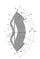
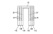
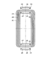
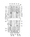
このコアレスコイル1は、中が空洞の軸平面形状コ形の円環状箱形(太鼓状)を成すものであり、周方向に少なくとも2分割され、機械角で180°以下となる複数のセパレートコイル2によって構成されている。各セパレートコイル2には、図1及び図2に示すように、ロータシャフト(図示省略)の径方向に形成される界磁束が通過する磁束鎖交部、即ち永久磁石のN極側に対応する磁束鎖交部(以下、N極側磁束鎖交部3と呼ぶ)と、永久磁石のS極側に対応する磁束鎖交部(以下、S極側磁束鎖交部3と呼ぶ)とが形成され、該N極側磁束鎖交部3とS極側磁束鎖交部3の導体を繋ぐ渡り線部4が各磁束鎖交部3,3の導体の両端においてロータシャフトと交わる面に沿って径方向内側に折り曲げられ、内ロータ磁石(図示省略)に跨がるような円環状箱形に形成されている。さらに、各磁束鎖交部3,3の導体の両端で径方向内側に折り曲げられた渡り線部4は、ロータシャフトと交わる面に沿って周方向に引き回されてロータシャフトの周辺を迂回する円弧状の配線とされ、N極側磁束鎖交部3とS極側磁束鎖交部3の導体を繋ぐ環状の導体を周方向に巻き上げるようにしてセパレートコイル2を構成している。これら複数のセパレートコイル2は、周方向に連結することによって、箱形のコアレスコイル1を構成する。 The coreless coil 1 is an annular box shape (drum shape) having a hollow axial plane shape inside, and is divided into at least two parts in the circumferential direction and has a mechanical angle of 180 ° or less. 2. As shown in FIGS. 1 and 2, each separate coil 2 corresponds to a magnetic flux linkage portion through which a field magnetic flux formed in the radial direction of a rotor shaft (not shown) passes, that is, the N pole side of the permanent magnet. flux-exchange unit (hereinafter, N is referred to as a pole flux-exchange unit 3 N), flux-exchange unit corresponding to the S pole side of the permanent magnets (hereinafter, referred to as S-pole side of flux exchange unit 3 S) and There is formed, the rotor shaft at both ends of the N pole side of flux exchange unit 3 N and S pole side flux-exchange unit 3 S crossover portion 4 each flux-exchange unit 3 connecting the conductors of N, 3 S conductors Is formed in an annular box shape that is bent radially inward along a surface intersecting with the inner rotor magnet and straddles the inner rotor magnet (not shown). Furthermore, the crossover portion 4 bent radially inward at both ends of the conductors of the magnetic flux linkage portions 3 N and 3 S is drawn in the circumferential direction along the surface intersecting with the rotor shaft, so that the periphery of the rotor shaft is surrounded. A separate coil 2 is configured by winding an annular conductor in a circumferential direction, which is a circular arc-shaped wiring that is detoured and that connects the conductors of the N pole side magnetic flux linkage part 3 N and the S pole side magnetic flux linkage part 3 S. Yes. The plurality of separate coils 2 are connected in the circumferential direction to constitute a box-shaped coreless coil 1.

本実施形態のコアレスコイル1は、外周面(胴部)にはロータシャフトと平行に巻かれた導体によって構成される磁束鎖交部、即ち界磁束が通過するN極側磁束鎖交部3とS極側磁束鎖交部3とを有し、胴の両面にはN極側磁束鎖交部3とS極側磁束鎖交部3の導体を繋ぐ渡り線が各磁束鎖交部3,3の導体の両端においてロータシャフトと直交する面に沿って径方向内側に折り曲げられ、かつ周方向に引き回されてロータシャフトと交わらないように巻線されている。 The coreless coil 1 of the present embodiment has a magnetic flux linkage portion constituted by a conductor wound in parallel with the rotor shaft on the outer peripheral surface (body portion), that is, an N pole side magnetic flux linkage portion 3 N through which a field magnetic flux passes. and and a S-pole side of flux exchange unit 3 S, on both sides of the trunk N pole flux-exchange unit 3 N and S pole side flux-exchange unit 3 over lines each magnetic flux linking the conductor of S linkage The ends of the conductors of the portions 3 N and 3 S are bent radially inward along a plane orthogonal to the rotor shaft, and wound around the rotor shaft so as not to cross the rotor shaft.

ここで、セパレートコイル2は、周方向にずらして互いに入り込ませながら組み合わせる入れ子構造にすることが好ましい。この場合、入れ子構造の複数のセパレートコイル2A,2B,2Cの組み合わせにより、両側面(胴の両面)の渡り線部4が軸方向に重なることで面積を増して1つのコアレスコイル1を構成するため、外周面(胴部)の各磁束鎖交部3,3に配置される導体10の巻数を増やすことができる。即ち、各磁束鎖交部3,3の巻線の量は、繋ぎとなる渡り線部4の面積(半径方向長さL)に依存する。依って、1ピースだけだと、磁束鎖交部が形成される外周長さLに対して渡り線が配線される領域部位の径方向長さLが狭い関係となる(L≫L)ので、導体10をたくさん巻けない。しかし、複数のセパレートコイル2を周方向にずらして順次入り込む入れ子構造として1つのコアレスコイル1を構成しているので、ギャップに配置されるコイル本数を増やすこと即ち磁束鎖交部のコイルをたくさん巻くことができる。依って、電圧を大きくして、出力を上げることができる。 Here, it is preferable that the separate coil 2 has a nested structure that is combined while being shifted in the circumferential direction and inserted into each other. In this case, a combination of a plurality of nested separate coils 2A, 2B, 2C causes the crossover portions 4 on both side surfaces (both sides of the body) to overlap in the axial direction, thereby increasing the area to form one coreless coil 1. Therefore, it is possible to increase the number of turns of the conductor 10 disposed at each magnetic flux linkage 3 N , 3 S on the outer peripheral surface (body portion). That is, the amount of winding in each of the magnetic flux interlinkage portions 3 N and 3 S depends on the area (radial length L 2 ) of the connecting wire portion 4 to be connected. Depending, when just one piece, radial length L 2 of the region sites connecting wire is wired to the outer peripheral length L 1 that flux-exchange unit is formed becomes narrower relationship (L 1 »L 2 ) Therefore, a lot of conductors 10 cannot be wound. However, since one coreless coil 1 is configured as a nested structure in which a plurality of separate coils 2 are shifted in the circumferential direction and sequentially inserted, increasing the number of coils arranged in the gap, that is, winding a lot of coils in the magnetic flux interlinking section. be able to. Therefore, the voltage can be increased to increase the output.

本実施形態においては、上述のセパレートコイル2は、N極側磁束鎖交部3の外側の端とS極側磁束鎖交部3の外側の端との間の成す角度θが機械角で120°の扇形に形成されており、その周方向両端に機械角で30°ずつの角度θのN極側磁束鎖交部3とS極側磁束鎖交部3とがそれぞれ形成され、その間のN極側磁束鎖交部3の内側の端とS極側磁束鎖交部3の内側の端との間の成す角度θが機械角で60°(電気角で120°)の空所(いずれの磁束鎖交部3,3も存在しない領域)7が形成されている。N極側磁束鎖交部3とS極側磁束鎖交部3との間の空所7には、入れ子構造を成す他のセパレートコイル2(本実施形態の場合、2Bあるいは2Cのいずれか一方または双方)のN極側磁束鎖交部3が配置される。そして、3ピースのセパレートコイル2A,2B,2Cが、磁束鎖交部の角度範囲θに相当する分、即ち30°ずつ周方向にずらして互いに入り込ませながら組み合わせる入れ子構造とされている。この3ピースのセパレートコイル2A,2B,2Cの組み合わせ(以下、セパレートコイル組み12と呼ぶ)によってコアレスコイル1の半体を形成する。尚、N極側磁束鎖交部3の中心とS極側磁束鎖交部3の中心との成す角度(本明細書では、極間隔と呼ぶ)θは機械角で90°(電気角で180°)に設定されている。また、各セパレートコイル2の内周側にはロータシャフトが貫通する孔を構成する円弧部5が設けられている。 In the present embodiment, the above-described separate coil 2 is configured such that the angle θ 1 formed between the outer end of the N pole side magnetic flux linkage portion 3 N and the outer end of the S pole side magnetic flux linkage portion 3 S is a machine. is formed in a sector 120 ° at the corner, mechanical angle at 30 ° by an angle theta 2 N-pole side of flux exchange unit 3 N and S pole side flux-exchange unit 3 S and each in its circumferential ends The angle θ 3 formed between the inner end of the N pole side magnetic flux linkage portion 3 N and the inner end of the S pole side magnetic flux linkage portion 3 S is 60 ° mechanical angle (electrical angle) 120 °) vacant space (region where none of the magnetic flux linkages 3 N and 3 S exist) 7 is formed. In the space 7 between the N pole side magnetic flux linkage portion 3 N and the S pole side magnetic flux linkage portion 3 S , another separate coil 2 having a nested structure (in this embodiment, either 2B or 2C) N-pole side of flux exchange unit 3 N in one or both) are arranged or. The three-piece separate coils 2A, 2B, 2C is an amount corresponding to the angular range theta 2 of flux-exchange unit, i.e. by shifting one by 30 ° circumferentially there is a nested structure combining while enter one another. A half of the coreless coil 1 is formed by a combination of these three pieces of separate coils 2A, 2B, and 2C (hereinafter referred to as a separate coil set 12). It should be noted that an angle (referred to as a pole interval in this specification) θ 4 formed by the center of the N pole side magnetic flux linkage portion 3 N and the center of the S pole side magnetic flux linkage portion 3 S is 90 ° (electrical) The angle is set to 180 °. In addition, an arc portion 5 that forms a hole through which the rotor shaft passes is provided on the inner peripheral side of each separate coil 2.

上述のセパレートコイル2は、入れ子構造とするため、正面(軸方向)視形状は同じでありながら幅(軸方向長さ)だけが異なる3種類の幅W,W,W(但し、W<W<W)のセパレートコイル2A,2B,2Cが2組(6ピース)作製され、これらが周方向にずらして組み合わされることによって1つのコアレスコイル1が形成される。そして、3種類の幅W,W,Wのセパレートコイル2A,2B,2Cを30°ずつ周方向にずらして順次入り込ませて入れ子構造とすることによって、3ピースのセパレートコイル2A,2B,2Cの各N極側磁束鎖交部3とS極側磁束鎖交部3とがそれぞれ連接されて、機械角で90°ずつのN極側磁束鎖交部3とS極側磁束鎖交部3とを有する機械角で180°の2組のセパレートコイル組み12が構成される。つまり、機械角で120°の扇形の6ピースのセパレートコイル2A,2B,2Cを入れ子構造にし、3ピースを入れ子式に連結した機械角で180°の一方のセパレートコイル組み12(コイル半体)と、3ピースを入れ子式に連結した機械角で180°の他方のセパレートコイル組み12(コイル半体)との複数のセパレートコイル組み12で構成されている。尚、セパレートコイル2の分割数は、上述のコイル半体で3分割(全周で6分割)に限られず、場合によつては、2分割(全周で4分割)あるいは4分割(全周で8分割)以上とすることも可能である。尚、本明細書では、セパレートコイル2A,2B,2Cの各々の幅W,W,Wは外寸で表しているが、セパレートコイル2Cの内側にセパレートコイル2Bが、さらにセパレートコイル2Bの内側にセパレートコイル2Aが、好ましくはそれぞれがたつき無く嵌まる込む関係にあることを意味しているものとする。 Since the above-described separate coil 2 has a nested structure, three types of widths W 1 , W 2 , W 3 (provided that the front (axial direction) view shape is the same but only the width (axial direction length) is different (however, Two sets (6 pieces) of separate coils 2A, 2B, 2C of W 1 <W 2 <W 3 ) are produced, and one coreless coil 1 is formed by combining these by shifting in the circumferential direction. Then, the three types of separate coils 2A, 2B, 2C having different widths W 1 , W 2 , W 3 are shifted in the circumferential direction by 30 ° and sequentially inserted to form a nested structure, thereby separating the three-piece separate coils 2A, 2B. , respectively and the N-pole side of flux exchange unit 3 N and S pole side flux-exchange unit 3 S of 2C are connected, the N-pole side of flux of each 90 ° in mechanical angle exchange unit 3 N and S pole side Two separate coil sets 12 having a mechanical angle of 180 ° having the magnetic flux linkage 3 S are formed. That is, a fan-shaped 6-piece separate coil 2A, 2B, 2C with a mechanical angle of 120 ° is nested, and one separate coil assembly 12 (coil half) with a mechanical angle of 180 ° with a mechanical angle of 3 pieces connected in a nested manner. And a plurality of separate coil sets 12 with the other separate coil set 12 (coil half body) having a mechanical angle of 180 ° with three pieces connected in a nested manner. Note that the number of divisions of the separate coil 2 is not limited to three divisions (six divisions on the entire circumference) in the above-described coil half body, and may be two divisions (four divisions on the whole circumference) or four divisions (all circumferences) 8 divisions) or more. In this specification, the widths W 1 , W 2 , and W 3 of the separate coils 2A, 2B, and 2C are represented by outer dimensions, but the separate coil 2B is further provided inside the separate coil 2C, and further the separate coil 2B. It is meant that the separate coils 2A are preferably fitted in each other without looseness.

これら2セットのセパレートコイル組み12は、内ロータ磁石27を挟んで向かい合わせにして周方向に連結される。例えば、ロータシャフトを中心に点対称の関係となるように2セットのセパレートコイル組み12を配置し、一方のセパレートコイル組み12の最も幅の狭いセパレートコイル2Aと他方のセパレートコイル組み12の最も幅の広いセパレートコイル2Cとが互いに嵌まり合うように向かい合わせて連結される。これにより、軸平面形状コ形の円環状箱形を成す1つのコアレスコイル1が構成される。尚、各セパレートコイル2を接着剤で固めるには、磁束鎖交部3,3と渡り線部4との双方を含む全領域を対象としても良いが、場合によっては部分的例えば渡り線部4だけ、あるいは磁束鎖交部3,3だけを固めるようにしても良い。また、自己融着性の導体・ワイヤ10を用いる場合には、巻線と同時にコイルが固められる。 These two sets of separate coil sets 12 are connected in the circumferential direction facing each other with the inner rotor magnet 27 therebetween. For example, two sets of separate coil sets 12 are arranged so as to have a point-symmetrical relationship about the rotor shaft, and the narrowest separate coil 2A of one separate coil set 12 and the widest width of the other separate coil set 12 are arranged. Are separated from each other so as to be fitted to each other. Thereby, one coreless coil 1 which comprises the axial plane shape U-shaped annular box shape is comprised. In order to solidify each separate coil 2 with an adhesive, the entire region including both the magnetic flux linkage portions 3 N and 3 S and the crossover portion 4 may be targeted. Only the portion 4 or only the magnetic flux linkage portions 3 N and 3 S may be hardened. When the self-bonding conductor / wire 10 is used, the coil is hardened simultaneously with the winding.

そして、各セパレートコイル2A,2B,2C毎に独立したコイルは、その巻始め8と巻き終り9とを選択的に他のセパレートコイルの巻始め8あるいは巻き終り9と接続することで、単相あるいは複相のコアレスコイル1を構成することができる。また、各セパレートコイル2A,2B,2Cを構成する導体10は、1本でも良いが、図11,12に示すように複数本で構成しても良い。即ち、同時に複数本、例えば4本の導体10を巻く場合には、2本ずつの第1のコイルXと第2のコイルYとに分けて、それらコイルX,Yを巻始め8あるいは巻き終り9の端末において直列または並列に接続可能にできる。   And the coil independent for each separate coil 2A, 2B, 2C can connect the winding start 8 and the winding end 9 with the winding start 8 or the winding end 9 of another separate coil, and can be single phase. Or the multi-phase coreless coil 1 can be comprised. Further, the number of conductors 10 constituting each of the separate coils 2A, 2B, 2C may be one, but a plurality of conductors 10 may be used as shown in FIGS. That is, when a plurality of, for example, four conductors 10 are wound at the same time, the two coils are divided into a first coil X and a second coil Y, and the coils X and Y are started to start 8 or end. 9 terminals can be connected in series or in parallel.

ここで、各セパレートコイル2A,2B,2Cには、導体10のみでセパレートコイル2を構成する場合には、接着剤などで固められた渡り線部4の導体間に締結用ボルトを通すための隙間即ち孔6が形成されることが望ましい。例えば図1及び図2に示すように、N極側磁束鎖交部3とS極側磁束鎖交部3のそれぞれのほぼ中心を通る法線上及びN極側磁束鎖交部3とS極側磁束鎖交部3との間の空所7のほぼ中心附近の法線上にそれぞれ隙間6が形成され、これら隙間6を複数のセパレートコイル2の間で重ねて締結用ボルト(図示省略)を通し、円弧状あるいは円環状の連結板24を介在させて相互に連結可能とされている。尚、複数のセパレートコイル2を相互に連結する連結板24は、アルミニウムや樹脂などの非磁性体であれば良く、好ましくは絶縁性を有するFRPなどの樹脂材料であることである。図中の符号24aは連結板24に開けられたボルト通し孔である。 Here, when the separate coil 2 is composed of only the conductor 10 in each of the separate coils 2A, 2B, 2C, a fastening bolt is passed between the conductors of the crossover portion 4 that is hardened with an adhesive or the like. A gap or hole 6 is preferably formed. For example, as shown in FIGS. 1 and 2, and the N-pole side of flux exchange unit 3 N and S pole side flux-exchange unit 3 each normal line on passing through the almost center and the N-pole side of flux exchange unit of S 3 N Clearances 6 are respectively formed on the normal lines in the vicinity of the center of the space 7 between the S pole side magnetic flux interlinkage 3 S and the fastening bolts (not shown) are overlapped between the plurality of separate coils 2. (Not shown), and can be connected to each other with an arcuate or annular connecting plate 24 interposed therebetween. The connecting plate 24 for connecting the plurality of separate coils 2 to each other may be a non-magnetic material such as aluminum or resin, and is preferably a resin material such as FRP having insulation properties. Reference numeral 24 a in the figure is a bolt through hole formed in the connecting plate 24.

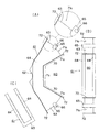
また、コアレスコイル1には、回転機の動作中に大きな力が働くことから、巻線後に接着剤を塗布して一体に成形するだけでは、巻線自体で必要な強度が得られない場合がある。そこで、各セパレートコイル2には、当該コイルを構成する導体を内側から支持して固定するコイルケースを併用することが好ましい。   In addition, since a large force is applied to the
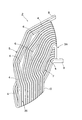
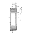
 coreless coil 1 during the operation of the rotating machine, the required strength cannot be obtained by the winding itself only by applying an adhesive after the winding and forming it integrally. is there. Therefore, it is preferable to use in combination with each separate coil 2 a coil case that supports and fixes a conductor constituting the coil from the inside.

本実施形態の場合、コイルケース11は、図2に示すように、各磁束鎖交部3,3の両側の渡り線部4をそれぞれ支える左右の側面支持部14並びにこれら側面支持部14を周方向の両端においてのみ部分的に連結して磁束鎖交部3,3を内側から支持する架橋部13とを有する一体的なコイルケース(以下、本明細書においては、一体形コイルケースと呼ぶ)が用いられている。この一体形コイルケース11は、N極側磁束鎖交部3とS極側磁束鎖交部3の領域においては、軸平面形状コ形を成している。尚、コイルケース11は、このような形態・形状に特に限られるものではなく、N極側磁束鎖交部3とS極側磁束鎖交部3の両端で径方向内側に折り曲げられた渡り線部4を少なくとも裏打ちするものであれば足りる。つまり、コイルケース11は、磁束鎖交部3,3の両端の渡り線部4のみを裏打ちする、互いに独立した2ピース例えば扇形の板材から成るコイルケースであっても良い(以下、本明細書においては、分離形コイルケースと呼ぶ)。このようなコイルケースにおいても、コイルケースを使って連結することにより、セパレートコイル2を組み立てる時に組み立て作業が容易になると共にコイルの角度・位置決めの精度が出し易くなる。 In the case of this embodiment, as shown in FIG. 2, the coil case 11 includes left and right side surface support portions 14 that respectively support the crossover portions 4 on both sides of the magnetic flux linkage portions 3 N and 3 S , and the side surface support portions 14. Are integrally connected only at both ends in the circumferential direction, and an integrated coil case having a bridging portion 13 that supports the magnetic flux linkage portions 3 N and 3 S from the inside (hereinafter referred to as an integral coil in the present specification). Called a case). The integral coil case 11, in the region of the N-pole side of flux exchange unit 3 N and S pole side flux-exchange unit 3 S, forms an axial plane shape co shaped. The coil case 11 is not particularly limited to such form and shape, it is bent radially inward at both ends of the N pole side of flux exchange unit 3 N and S pole side flux-exchange unit 3 S Any material that at least lines the crossover part 4 is sufficient. That is, the coil case 11 may be a coil case made of two independent pieces, for example, fan-shaped plate members, which line only the connecting wire portions 4 at both ends of the magnetic flux linkage portions 3 N and 3 S (hereinafter referred to as the present case). In the specification, this is called a separate coil case). Even in such a coil case, by connecting using the coil case, when assembling the separate coil 2, the assembling work is facilitated and the coil angle and positioning accuracy are easily obtained.

本実施形態の一体形コイルケース11は、セパレートコイル2と同じ角度θの扇形を成し、内周にロータシャフトが貫通する孔を形成する円弧部15を有し、かつ外周にロータシャフトと平行な角度θの架橋部13と、他のセパレートコイル2の磁束鎖交部3,3が径方向に通過する角度θの空所17とを有し、1つのコイルケースのN極側磁束鎖交部3とS極側磁束鎖交部3の間に他のコイルケースのN極側磁束鎖交部3が順次入り込み、左右両面の側面支持部14とが軸方向に部分的に重なり合う入れ子構造とされている。 The integrated coil case 11 of the present embodiment forms a fan shape having the same angle θ 1 as that of the separate coil 2, has an arc portion 15 that forms a hole through which the rotor shaft passes on the inner periphery, and the rotor shaft on the outer periphery. The bridge portion 13 having a parallel angle θ 2 and the space 17 having an angle θ 3 through which the magnetic flux linkage portions 3 N and 3 S of the other separate coil 2 pass in the radial direction have an N of one coil case. sequentially enter the pole flux-exchange unit 3 N and S pole side flux-exchange unit 3 S N pole side flux-exchange unit 3 N other coil case between the left and right both sides of the side supports 14 are axially The nesting structure is partially overlapped with each other.

コイルケース11の表面には、セパレートコイル2の磁束鎖交部3,3及び渡り線部における位置を定めるコイル位置決め溝が設けられている。このコイル位置決め溝は、磁束鎖交部及び渡り線部における導体10の位置を定めるものであれば特定の構造等に限られるものではないが、磁束鎖交部3,3及び渡り線部4における導体10の巻位置を決める多数の導体ガイド溝19の集合から成るもの(図3参照)、あるいは磁束鎖交部3,3及び渡り線部4における導体10の配置領域の大枠だけを定めたもの(図4参照)であることが好ましい。 On the surface of the coil case 11, coil positioning grooves that determine the positions of the magnetic flux linkage portions 3 N and 3 S and the crossover portion of the separate coil 2 are provided. The coil positioning groove is not limited to a specific structure and the like as long as it determines the position of the conductor 10 in the magnetic flux linkage part and the crossover part, but the magnetic flux linkage parts 3 N and 3 S and the crossover part 4 consisting of a set of a large number of conductor guide grooves 19 for determining the winding position of the conductor 10 (see FIG. 3), or only a large frame of the arrangement area of the conductor 10 in the magnetic flux linkage portions 3 N and 3 S and the crossover portion 4 Is preferable (see FIG. 4).

例えば、図3に示すコイル位置決め溝は、導体10を巻回するための位置を導く複数本の導体ガイド溝19を並べることによって、外周側の架橋部13にロータシャフトと平行に導体10が配置されるN極側磁束鎖交部3及びS極側磁束鎖交部3を収める磁束鎖交部溝領域20、ロータシャフトと交わる面に渡り線を収める渡り線溝領域21をそれぞれ形成するものであり、導体10を導体ガイド溝19に沿って押し込むように巻き付けることによって当該コイルケース11を巻芯としてN極側磁束鎖交部3とS極側磁束鎖交部3と渡り線部4とが軸平面でコの字形を成すように巻回される。導体ガイド溝19は導体10の巻き付け位置を案内すると共に、絶縁性の壁22を両側に形成して導体10の絶縁性を確保するものとして機能する。加えて、コイルケース11は巻芯として機能するので導体10が巻き付け易く、セパレートコイル2の作製を容易にする。さらに、導体ガイド溝19に強制的に導体10を押し込んで巻き込んで行けるので、加工し易く太い銅線を使える。したがって、高出力化が可能となる。また、エナメルが巻線時に剥げても、樹脂で囲われているので、絶縁できる。 For example, in the coil positioning groove shown in FIG. 3, the conductor 10 is arranged in parallel with the rotor shaft at the bridge portion 13 on the outer peripheral side by arranging a plurality of conductor guide grooves 19 that guide the position for winding the conductor 10. N pole side magnetic flux linkage part 3 N and S pole side magnetic flux linkage part 3 S are formed, and a magnetic flux linkage part groove area 20 for accommodating the crossover line is formed on the surface intersecting with the rotor shaft. By winding the conductor 10 so as to be pushed in along the conductor guide groove 19, the N pole side magnetic flux linkage portion 3 N and the S pole side magnetic flux linkage portion 3 S are connected with the coil case 11 as a winding core. The portion 4 is wound so as to form a U shape in the axial plane. The conductor guide groove 19 functions to guide the winding position of the conductor 10 and to ensure insulation of the conductor 10 by forming insulating walls 22 on both sides. In addition, since the coil case 11 functions as a winding core, the conductor 10 can be easily wound and the separate coil 2 can be easily manufactured. Further, since the conductor 10 can be forcedly pushed into the conductor guide groove 19 and wound, a thick copper wire that can be easily processed can be used. Therefore, high output can be achieved. Even if the enamel is peeled off during winding, it can be insulated because it is surrounded by resin.

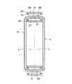
また、図4に示すコイル位置決め溝は、予め専用巻線機あるいは汎用巻線機や汎用フォーミング加工機などを使って巻かれたセパレートコイル2を嵌め込む際の位置・空間を規定するものであり、外周側の架橋部13の両端に配置されたストッパ23によって区間が定められたN極側磁束鎖交部3及びS極側磁束鎖交部3を収容する磁束鎖交部溝領域20と、渡り線部4が占位する外枠を示す渡り線溝領域21とを有する。渡り線溝領域21は、単なる平面でも良いが、予め機械巻されたセパレートコイル2の渡り線部4の輪郭に沿った凹部としても良く、要は渡り線部4が嵌まり込むスペースが確保されていれば足りる。このため、機械巻きなどで予め成形されたセパレートコイル2を組み立てる際に、コイルケース11に嵌め込んで固定してから連結することによって、組み立て作業が容易になると共に、コイルの角度・位置決めの精度が出し易くなる。尚、このコイル位置決め溝には、場合によっては巻線機やフォーミング加工機などで導体を直接巻着付けてセパレートコイル2を形成するようにしても良い。 In addition, the coil positioning groove shown in FIG. 4 defines the position and space for fitting the separate coil 2 wound in advance using a dedicated winding machine, a general-purpose winding machine, a general-purpose forming machine, or the like. , flux-exchange unit groove region 20 for accommodating the ends N pole flux-section by a stopper 23 which is arranged stipulated in exchange unit 3 N and S pole side flux-exchange unit 3 S of the outer peripheral side of the bridge portion 13 And a crossover groove region 21 indicating an outer frame occupied by the crossover portion 4. The crossover groove region 21 may be a mere flat surface, but may be a recess along the contour of the crossover portion 4 of the separate coil 2 that has been pre-machined, and the space for fitting the crossover wire portion 4 is ensured. If it is, it is enough. For this reason, when assembling the separate coil 2 formed in advance by mechanical winding or the like, the assembly operation is facilitated by fitting and fixing the coil 2 into the coil case 11 and fixing the coil angle and positioning accuracy. Becomes easy to take out. In some cases, a separate coil 2 may be formed by directly winding a conductor in the coil positioning groove with a winding machine or a forming machine.

コイルケース11は、絶縁性を有し、安価で加工し易いプラスチック製であることが好ましいが、これに特に限られるものではなく、FRPやその他の非磁性材例えばアルミニウムやセラミックスでも可能である。また、場合によっては、コイルケース11は、非磁性材でなくとも良い。さらに、エンジニアリングプラスチックやナイロンなどの耐熱性樹脂であることは好ましいが、発熱が予想される温度が例えば100℃〜120℃程度であれば、一般的な樹脂材料でも十分に耐え得るので、特に耐熱性樹脂には拘らない。使用時の発熱に耐える程度の物性を有するプラスチックであれば用いることができる。勿論、導体10の絶縁皮膜(エナメル)が強靱で曲げたときに剥がれなければ、コイルケース11を絶縁材料で構成する必要はないが、コイルケース11が絶縁性であれば万が一絶縁皮膜が剥がれたときにも、側方の絶縁材(樹脂)の壁22と周りの導体10のエナメルとが存在するため、絶縁性を損なうことが無く、安心である。   The coil case 11 is preferably made of plastic that is insulating, inexpensive, and easy to process, but is not particularly limited to this, and may be FRP or other nonmagnetic material such as aluminum or ceramics. In some cases, the coil case 11 may not be a non-magnetic material. Furthermore, it is preferable to use a heat-resistant resin such as engineering plastic or nylon. However, if the temperature at which heat generation is expected is, for example, about 100 ° C. to 120 ° C., even a general resin material can be sufficiently tolerated. Regardless of the nature of the resin. Any plastic having physical properties enough to withstand heat generation during use can be used. Of course, if the insulating film (enamel) of the conductor 10 is strong and does not peel off when bent, the coil case 11 need not be made of an insulating material. However, if the coil case 11 is insulative, the insulating film should be peeled off. Sometimes, the side wall 22 of the insulating material (resin) and the enamel of the surrounding conductor 10 are present, so that the insulation is not impaired and it is safe.

また、コイルケース11にはコイルケース同士を連結するための締結用ボルト(図示省略)を通す孔16が設けられている。ボルト通し孔16は、例えば図3,4に示すように、コイルケース11の内周縁附近に円周方向に均等に(両端から15°の位置から30°間隔で)配置されて複数箇所例えば4箇所設けられている。また、場合によっては、複数本の導体ガイド溝19を並べることによって形成されるコイルケース11の側面支持部14の渡り線溝領域21の間の隙間18の位置にボルト通し孔(図示省略)を設けるようにしても良い。これらボルト通し孔16を複数のセパレートコイル2の間で重ねて締結用ボルトを通し、図5に示すように、連結板24を介在させて相互に連結することによって、コアレスコイル1が組み立てられる。この場合、コアレスコイル1は、コイルケース11によって内側からバックアップされているので、コイル同士を接着材で固めたものを連結するときよりも、コイルとしての機械的強度が増す。   Further, the coil case 11 is provided with a hole 16 through which a fastening bolt (not shown) for connecting the coil cases is passed. For example, as shown in FIGS. 3 and 4, the bolt through holes 16 are arranged evenly in the circumferential direction in the vicinity of the inner peripheral edge of the coil case 11 (at intervals of 30 ° from 15 ° from both ends). There are places. In some cases, bolt through holes (not shown) are formed at the positions of the gaps 18 between the crossover groove regions 21 of the side support portions 14 of the coil case 11 formed by arranging a plurality of conductor guide grooves 19. You may make it provide. The coreless coil 1 is assembled by overlapping the bolt through holes 16 between the plurality of separate coils 2, passing the fastening bolts, and connecting the bolts through the connecting plate 24 as shown in FIG. 5. In this case, since the coreless coil 1 is backed up from the inside by the coil case 11, the mechanical strength as a coil is increased as compared with the case where the coils are bonded together with an adhesive.

上述の各セパレートコイル2は、大きく分けて、コイルケース11を用いずに導体10のみで構成するものと、コイルケース11を併用するものとがある。さらに、コイルケース11を併用するセパレートコイル2としては、巻線を作製してからコイルケース11に嵌めるものと、コイルケース11を巻心として導体10を巻き上げることにより一体化するものとがある。そして、上述の各セパレートコイル2を作製する手法としては、従来のコアレスコイル1と同様に専用巻線機を用いたり、あるいは汎用巻線機や汎用フォーミング加工機、さらには手巻きで、上述の形態のセパレートコイル2を巻き上げることができる。さらには、コイルケース11を利用して汎用巻線機や汎用フォーミング加工機、さらには手巻きで巻線することができる。   Each of the above-described separate coils 2 can be broadly divided into one constituted by only the conductor 10 without using the coil case 11 and one using the coil case 11 in combination. Furthermore, as the separate coil 2 that uses the coil case 11 in combination, there are a coil that is wound and then fitted into the coil case 11, and a coil that is integrated by winding the conductor 10 around the coil case 11. And as a method of producing each above-mentioned separate coil 2, using a special winding machine like the conventional coreless coil 1, or a general-purpose winding machine, a general-purpose forming machine, and also manual winding, the above-mentioned The form separate coil 2 can be wound up. Furthermore, the coil case 11 can be used for winding by a general-purpose winding machine, a general-purpose forming machine, or by manual winding.

例えば、コイルケース11に導体を直に巻くことで構成されるセパレートコイル2の場合を例に挙げると、以下のようにして製作される。まず、内ロータ磁石27が収容される空間即ちコアレスコイル1の内部空間に相当する空間を埋める芯材(図示省略)を用い、該芯材の表面に図3,4に示す一体形あるいは分離形のコイルケース11を取り付ける。そして、コイルケース11の上からエナメル線・導体10を導体ガイド溝19の内部に押し込みながら溝19に沿って巻き付けることによって、セパレートコイル2を作製する。この巻線作業においては、コイルケース11がガイド部材として機能するため、専用巻線機の必要が無い。即ち、汎用巻線機や汎用フォーミング加工機あるいは手巻きでも、コイルケースの溝に沿って導体10を巻くことで、セパレートコイル2が容易に製作可能である。そして、導体10を巻き上げている最中に、あるいは導体10を巻き上げた後に、導体同士並びに導体10とコイルケース11との間を接着剤で固定して、コイルケース11で裏打ちされたセパレートコイル2を得る。尚、芯材は、巻線完了後、セパレートコイル2から取り外される。   For example, taking the case of the separate coil 2 configured by winding a conductor around the coil case 11 as an example, the coil case 11 is manufactured as follows. First, a core material (not shown) that fills the space in which the inner rotor magnet 27 is accommodated, that is, the space corresponding to the inner space of the coreless coil 1, is used, and the surface of the core material is integrated or separated as shown in FIGS. The coil case 11 is attached. The separate coil 2 is manufactured by winding the enameled wire / conductor 10 from above the coil case 11 along the groove 19 while being pushed into the conductor guide groove 19. In this winding work, since the coil case 11 functions as a guide member, there is no need for a dedicated winding machine. That is, the separate coil 2 can be easily manufactured by winding the conductor 10 along the groove of the coil case by a general-purpose winding machine, a general-purpose forming machine, or manual winding. Then, during the winding of the conductor 10 or after the winding of the conductor 10, the conductors and between the conductor 10 and the coil case 11 are fixed with an adhesive, and the separate coil 2 lined with the coil case 11 is used. Get. The core material is removed from the separate coil 2 after the winding is completed.

このようにして、幅の異なる芯材並びにコイルケース11を用いて、正面視形状は同じでありながら幅だけが異なる複数種のセパレートコイル2を作製する。例えば本実施形態の場合には、前述した図5〜図8に示すような正面(軸方向)視形状は同じでありながら幅(軸方向長さ)だけが異なる3種類の幅W,W,W(但し、W<W<W)のセパレートコイル2を2組作製する。 In this way, using the core material and the coil case 11 having different widths, a plurality of types of separate coils 2 having the same front view shape but different widths are produced. For example, in the case of the present embodiment, three types of widths W 1 and W having the same front (axial direction) view shape as shown in FIGS. 5 to 8 but different in width (axial length) are the same. Two sets of separate coils 2 of W 2 and W 3 (W 1 <W 2 <W 3 ) are produced.

このセパレートコイル2は、例えば機械角で120°の扇形に形成されており、その周方向両端に機械角で30°(電気角で60°)ずつのN極側磁束鎖交部3とS極側磁束鎖交部3とがそれぞれ形成され、その間に機械角で60°(電気角で120°)の空所7,17が形成されている。したがって、3種類の幅W,W,Wのセパレートコイル2を30°ずつ周方向にずらして順次入り込ませる入れ子構造とすることによって、最も幅が広いセパレートコイル2のN極側磁束鎖交部3とS極側磁束鎖交部3との間の空所7,17に次に幅の広いセパレートコイル2と最も幅の狭いセパレートコイル2の各N極側磁束鎖交部3が順次突出するように配置される。同時に、最も幅が広いセパレートコイル2のS極側磁束鎖交部3の周方向外側に次に幅の広いセパレートコイル2と最も幅の狭いセパレートコイル2の各S極側磁束鎖交部3が順次突出するように連接されて、機械角で90°(電気角で180°)ずつのN極側磁束鎖交部3とS極側磁束鎖交部3とを有する機械角で180°の2組のセパレートコイル組み12が構成される(図5参照)。複数のセパレートコイル2の連結は、入れ子構造に組み立てる際に、内周縁周りに配置されたボルト通し孔16を重ねて締結用ボルトを通して締結することで行われる。この場合、同時に、コイルケース11の側面支持部14の導体が敷設されていない隙間部分(図4のコイルケースの場合には、セパレートコイル2の渡り線部4の隙間6が配置される位置)18にボルト通し用の孔あるいはナットを設けることで、より強固に連結できるようにしても良い。 The separate coil 2 is formed, for example, in a fan shape with a mechanical angle of 120 °, and N pole-side magnetic flux linkages 3 N and S each having a mechanical angle of 30 ° (electrical angle of 60 °) at both ends in the circumferential direction. are formed respectively with pole flux-exchange unit 3 S, it is void 7 and 17 form a 60 ° in mechanical angle therebetween (120 ° in electrical angle). Accordingly, the N-pole side magnetic flux chain of the widest separate coil 2 is formed by adopting a nested structure in which the three types of width W 1 , W 2 , W 3 separate coils 2 are sequentially shifted in the circumferential direction by 30 °. exchange unit 3 N and S pole side flux-exchange unit 3 each N pole flux-of the cavity 7, 17 to the next narrow separate coil 2 wide widest with separate coil 2 width between the S and Transportation 3 N are arranged so as to sequentially protrude. At the same time, the widest separate coil 2 S-pole side of flux exchange unit 3 each S-pole side of flux of S in the circumferential direction outside the next narrow wide separation coil 2 and widest width separate coil 2 and Transportation 3 S is connected so that it protrudes sequentially, and it has a mechanical angle of 90 ° in mechanical angle (180 ° in electrical angle) and N pole side magnetic flux linkage part 3 N and S pole side magnetic flux linkage part 3 S. Two separate coil sets 12 of 180 ° are configured (see FIG. 5). The plurality of separate coils 2 are connected by overlapping bolt through holes 16 arranged around the inner peripheral edge and fastening them through fastening bolts when assembling the nested structure. In this case, at the same time, the gap portion where the conductor of the side surface support portion 14 of the coil case 11 is not laid (in the case of the coil case of FIG. 4, the position where the gap 6 of the crossover portion 4 of the separate coil 2 is disposed). 18 may be provided with a bolt-through hole or nut so as to be able to be connected more firmly.

そこで、この2組のセパレートコイル組み12を、周方向に連結することによって、円環状の箱形コアレスコイル1を組み立てることができる。ここで、2組のセパレートコイル組み12は、図9及び図10に示すように、点対称の関係となるように配置して連結することで、つまり一方のセパレートコイル組み12の最も幅の狭いセパレートコイル2Aと他方のセパレートコイル2組の最も幅の広いセパレートコイル2Cとが互いに嵌まり合うように向かい合わせて連結されることで、1つの円環状の箱形コアレスコイル1が構成される。斯くして、複数のセパレートコイル2を周方向にずれる入れ子構造として1つのコアレスコイル1を構成しているので、必要数のセパレートコイル2を組み合わせることで、外周面・ギャップに配置されるコイル本数を増やして出力を上げることができる。向かい合わせに嵌め合わされたセパレートコイル組み12は、少なくとも両コイル組み12の間に跨がるように配置される半円状(場合によっては円環状)の連結板24を宛がって、締結用ボルトによって相互に連結される。連結板24のボルト通し孔24aとコイルケース11のボルト通し孔16とは位置合わせされて、締結用ボルトが通される。   Therefore, the annular box-shaped coreless coil 1 can be assembled by connecting the two separate coil sets 12 in the circumferential direction. Here, as shown in FIGS. 9 and 10, the two separate coil sets 12 are arranged and connected so as to have a point-symmetrical relationship, that is, one of the separate coil sets 12 has the narrowest width. One annular box-shaped coreless coil 1 is configured by connecting the separate coil 2A and the other pair of separate coils 2C facing each other so as to fit each other. Thus, since one coreless coil 1 is configured as a nested structure in which a plurality of separate coils 2 are shifted in the circumferential direction, the number of coils arranged on the outer peripheral surface / gap can be obtained by combining the required number of separate coils 2. Can be increased to increase the output. The separate coil assembly 12 fitted face-to-face is connected to a semi-circular (annular) connection plate 24 disposed so as to straddle at least between the two coil assemblies 12 for fastening. Connected to each other by bolts. The bolt through hole 24a of the connecting plate 24 and the bolt through hole 16 of the coil case 11 are aligned, and the fastening bolt is passed therethrough.

特に、図3に示す実施形態の溝付きコイルケース11を用いる場合には、溝19に沿って導体10を強制的に埋め込みながら規則正しく巻いて行けるので、太い導体(銅線)でも巻くことができる。通常、導体10の直径が太いと、銅が持っている機械的抵抗で細かい細工ができず巻き難い。したがって、従来のコアレスコイル1では太い線は使えなかった。従来のコアレスコイル1の導体の直径は、通常0.1mm〜0.5mm前後、太くても概ね0.8mm〜1mm程度であるが、本発明では、直径2mm程度でも十分に巻ける。しかして、太い導体(4〜6倍の断面積)を使用できるので高出力が得られる。   In particular, when the grooved coil case 11 of the embodiment shown in FIG. 3 is used, the conductor 10 can be wound regularly while being forcibly embedded along the groove 19, so that even a thick conductor (copper wire) can be wound. . Usually, if the diameter of the conductor 10 is large, it is difficult to wind because a fine work cannot be performed due to the mechanical resistance of copper. Therefore, the conventional coreless coil 1 cannot use a thick line. The diameter of the conductor of the conventional coreless coil 1 is usually about 0.1 mm to 0.5 mm, and even if it is thick, it is about 0.8 mm to 1 mm. However, in the present invention, even a diameter of about 2 mm can be wound sufficiently. Since a thick conductor (4 to 6 times the cross-sectional area) can be used, high output can be obtained.

しかも、複数本例えば4〜8本の導体10を1つの溝19に入れて巻線し、コイル巻始め8と巻き終り9との端末を利用して複数本の導体10から成るコアレスコイル1をシリーズに接続したり、パラレルに接続したりすることを端子部分で任意に選択できる。このようなセパレートコイル2によれば、インバータを使わなくとも、効率を変えずに電圧を変換できる。例えば、図11及び図12に示す4本の導体10を巻いたセパレートコイル2によれば、2本ずつの第1のコイルXと第2のコイルYの2組に分けた場合、100v,5Aの電流を流す2本ずつのコイルX,Yを並列に接続すれば、100v,10Aで1kwの出力が得られ、直列に接続すれば、200v,5Aで1kwの出力が得られる。   In addition, a plurality of conductors 10, for example, 4 to 8 conductors 10 are wound in one groove 19, and the coreless coil 1 composed of the plurality of conductors 10 is formed using the ends of the coil winding start 8 and winding end 9. Connection to series or parallel connection can be arbitrarily selected at the terminal part. According to such a separate coil 2, the voltage can be converted without changing the efficiency without using an inverter. For example, according to the separate coil 2 in which the four conductors 10 are wound as shown in FIGS. 11 and 12, when divided into two pairs of the first coil X and the second coil Y, 100v, 5A If two coils X and Y that pass the current of 2 are connected in parallel, an output of 1 kW can be obtained at 100 V and 10 A, and if connected in series, an output of 1 kW can be obtained at 200 V and 5 A.

以上のように構成されたコアレスコイル1は、回転機のステータコイルあるいはロータコイルとして組み込むことができる。例えば、永久磁石ラジアル型回転機のステータコイルとして用いることができる。   The coreless coil 1 configured as described above can be incorporated as a stator coil or a rotor coil of a rotating machine. For example, it can be used as a stator coil of a permanent magnet radial type rotating machine.

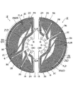
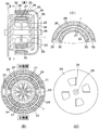
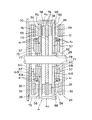
図15に、本発明のコアレスコイル1をラジアル型2極単相交流発電機のステータコイルとして適用した一実施形態を示す。このラジアル型2極単相交流発電機は、コアレスコイル1の径方向内側に内ロータ25が、外側に外ロータ26が配置されて、外ロータ26の永久磁石27と内ロータ25の永久磁石28との間のギャップに磁束鎖交部3,3が配置されるように構成されている。ロータシャフト29は、コアレスコイル1の内周側のホールを貫通し、内ロータ25と外ロータ26とを固定して支持している。他方、コアレスコイル1は静止物例えばエンジンボディ(図示省略)などにコイル固定プレート30を介して固定されている。尚、図中の符号31は通風孔、32はテーパー型磁石ヨーク、33はバックヨーク、34は内ロータファン、35は外ロータファンである。 FIG. 15 shows an embodiment in which the coreless coil 1 of the present invention is applied as a stator coil of a radial type two-pole single-phase AC generator. In this radial type two-pole single-phase AC generator, the inner rotor 25 is arranged on the radially inner side of the coreless coil 1, and the outer rotor 26 is arranged on the outer side, and the permanent magnet 27 of the outer rotor 26 and the permanent magnet 28 of the inner rotor 25. The magnetic flux linkage portions 3 N and 3 S are arranged in the gap between the two. The rotor shaft 29 penetrates the hole on the inner peripheral side of the coreless coil 1 and fixes and supports the inner rotor 25 and the outer rotor 26. On the other hand, the coreless coil 1 is fixed to a stationary object such as an engine body (not shown) via a coil fixing plate 30. In the figure, reference numeral 31 is a vent hole, 32 is a tapered magnet yoke, 33 is a back yoke, 34 is an inner rotor fan, and 35 is an outer rotor fan.

箱形コアレスコイル1は、動作時に大電流が供給されるため発熱が大きいことから、放熱には特に留意する必要がある。放熱は、コアレスコイル1から空気中への熱放散と、渡り線部4からのコアレスコイル1の支持体例えばコイル固定プレート30への熱伝導による放熱が主となる。そこで、例えば、ロータシャフト29と直交する外ロータ26の側面には、切り起こしによりフィンが形成されて放熱用の外ロータファン35が構成されている。また、内ロータ25の内周面側には、径方向内側に向けて放射状に形成されるフィンが一体成形されて放熱用の内ロータファン34が構成されている。勿論、本実施例では、外ロータ26並びに内ロータ25に放熱フィンを設けてコイル1の放熱を促進するファン構造としているが、場合によっては全体を覆うカバー部材や蓋体などにフィンを設けて放熱させるようにして良い。また、熱伝導による放熱を促進するため、例えばコイル固定プレート30にコアレスコイル1を接着するための接着剤に、熱伝導を助長するように、好ましくは絶縁性または高比抵抗の高熱伝導性の粉体を混合して、コイル固定プレート30などへの熱伝導を大きくするようにしても良い。   Since the box-shaped coreless coil 1 generates a large amount of current during operation and generates a large amount of heat, special attention must be paid to heat dissipation. The heat radiation is mainly performed by heat dissipation from the coreless coil 1 into the air and heat conduction from the crossover portion 4 to the support of the coreless coil 1, for example, the coil fixing plate 30. Therefore, for example, fins are formed by cutting and raising on the side surface of the outer rotor 26 orthogonal to the rotor shaft 29 to constitute an outer rotor fan 35 for heat dissipation. Further, on the inner peripheral surface side of the inner rotor 25, fins that are radially formed toward the inner side in the radial direction are integrally formed to constitute an inner rotor fan 34 for heat dissipation. Of course, in the present embodiment, the outer rotor 26 and the inner rotor 25 are provided with heat dissipating fins to promote the heat dissipating of the coil 1, but in some cases, fins are provided on a cover member or a cover that covers the whole. It is possible to dissipate heat. Further, in order to promote heat dissipation by heat conduction, for example, an adhesive for bonding the coreless coil 1 to the coil fixing plate 30 is preferably an insulating or high specific resistance high thermal conductivity so as to promote heat conduction. Powders may be mixed to increase heat conduction to the coil fixing plate 30 or the like.

ここで、コアレスコイル1は、入れ子となった3種のセパレートコイル2A,2B,2Cが30°ずつ周方向にずらして重なるように組み合わされることによって180°のセパレートコイル組み12が2組形成される。これら一対のセパレートコイル組み12を内ロータ25を挟み込むように組み合わせると共に連結板にて相互に連結することで、内ロータ25を包み込む箱状のコアレスコイル1が組み立てられる。その後、コアレスコイル1の外側に嵌め込むように軸方向から外ロータ26が組み込まれ、コアレスコイル1を挟んで内ロータ25と外ロータ26とが径方向に対向するように配置される。これによって、コアレスコイル1の磁束鎖交部3,3より僅かに広い間隔(必要最小限の間隔)をあけて環状に配置された外ロータ磁石28と内ロータ磁石27とが配置されたラジアル型2極単相交流発電機が構成される。尚、コアレスコイル1の組み立ては、上述の手法に特に限られず、内ロータ25を囲うように、セパレートコイル2を1ピースずつ順次入り込ませながら内ロータ25の周りに1ピース毎嵌め込むように組み付けることで、内ロータ25の全周を囲うように組み立てても良い。 Here, the coreless coil 1 is combined with three nested separate coils 2A, 2B, and 2C so as to overlap each other by 30 ° in the circumferential direction, thereby forming two 180 ° separate coil sets 12. The The pair of separate coil assemblies 12 are combined so as to sandwich the inner rotor 25 and are connected to each other by a connecting plate, whereby the box-shaped coreless coil 1 that wraps the inner rotor 25 is assembled. Thereafter, the outer rotor 26 is assembled from the axial direction so as to be fitted to the outside of the coreless coil 1, and the inner rotor 25 and the outer rotor 26 are arranged so as to face each other across the coreless coil 1. As a result, the outer rotor magnet 28 and the inner rotor magnet 27 arranged in an annular shape with a slightly wider interval (minimum necessary interval) than the magnetic flux interlinkage portions 3 N and 3 S of the coreless coil 1 are arranged. A radial type two-pole single-phase AC generator is configured. The assembly of the coreless coil 1 is not particularly limited to the above-described method, and the coreless coil 1 is assembled so as to be fitted around the inner rotor 25 while the separate coils 2 are sequentially inserted one by one so as to surround the inner rotor 25. Thus, it may be assembled so as to surround the entire circumference of the inner rotor 25.

このラジアル型2極単相交流発電機は、ワイヤを巻いたコイルでかつ渡り線部を有しながらも、永久磁石27,28とコアレスコイル1とをラジアル方向に必要最小限の僅かなギャップを隔てて対向するように組み立てられるので、鎖交磁束の減少を防いで発電機の高効率化・高出力化を実現すると共に、ラジアル方向並びに軸方向のコアレスコイル1の寸法を最小限のものとして、発電機の小型化・軽量化を可能とする。しかも、組み立てられたコアレスコイル1は軸平面形状コ形の円環状箱形を成すため、両端で支持可能で機械的強度が高いため、また太い導体が使用できるため、高出力を可能とする。   This radial type two-pole single-phase AC generator is a coil wound with a wire and has a crossover part, but the permanent magnets 27 and 28 and the coreless coil 1 have a minimal gap in the radial direction. Since they are assembled so as to be opposed to each other, the reduction of interlinkage magnetic flux is prevented to achieve higher efficiency and higher output of the generator, while minimizing the dimensions of the coreless coil 1 in the radial direction and the axial direction. The generator can be made smaller and lighter. In addition, since the assembled coreless coil 1 is formed in the shape of a ring-shaped box having an axial plane shape, it can be supported at both ends and has high mechanical strength, and a thick conductor can be used, thereby enabling high output.

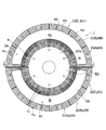
また、コアレスコイル1の配線は、図16に示すように、セパレートコイルC−Bが接続箇所37で、コイルB−Aが接続箇所38で、コイルA−Cが接続箇所39で、コイルC−Bが接続箇所40で、コイルB−Aが接続箇所41でそれぞれ接続されることによって、コアレスコイル1としての巻始め36から巻き終り42までが1本のコイルとされている。   Further, as shown in FIG. 16, the wiring of the coreless coil 1 is such that the separate coil C-B is at the connection point 37, the coil B-A is at the connection point 38, the coil A-C is at the connection point 39, and the coil C- By connecting B at the connection point 40 and the coil B-A at the connection point 41, the winding from the winding start 36 to the winding end 42 as the coreless coil 1 is a single coil.

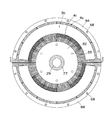
この2極単相交流発電機は、図16に示すように、外ロータ磁石28は、例えば上半分側にN極が、下半分側にS極が配置されている。他方、内ロータ磁石27は、上半分側にS極が、下半分側にN極が配置されている。本実施形態の場合は、外ロータ25と内ロータ26とにそれぞれ磁石27,28が取り付けられているが、片側が磁石でもう一方は界磁ヨークで構成するようにしても良い。   In this two-pole single-phase AC generator, as shown in FIG. 16, the outer rotor magnet 28 has, for example, an N pole on the upper half side and an S pole on the lower half side. On the other hand, the inner rotor magnet 27 has an S pole on the upper half side and an N pole on the lower half side. In the present embodiment, the magnets 27 and 28 are attached to the outer rotor 25 and the inner rotor 26, respectively, but one side may be a magnet and the other may be a field yoke.

ここで、2極単相交流発電機における磁石角度は、N極及びS極のそれぞれにおいて90°以上180°以下であり、好ましくは120°〜180°、より好ましくは120°〜150°、最も好ましくは150°程度とすることである。そこで、本実施形態においては、N極側(上半分)とS極側(下半分)とは、図16に示すように、各々150°の角度の永久磁石がその両端において30°ずつの隙間を設けて配置されている。内あるいは外の永久磁石27,28は、1個の大きな塊の磁石でも良いが、150°の広範囲な角度を1個の磁石で構成すると、磁石面積が大きくなり磁束密度が著しく低下する。このことを防ぐために、図15(D)に示すように、外ロータ磁石28を分割して複数の磁石片として周方向に隙間無く配置すると共に、反対極となる内ロータ磁石27も同様に分割して、分割された外ロータ磁石28の境目に内ロータ磁石27を配置することが好ましい。この場合、隣接する磁石片同士は同極で反発するため、分割された磁石の背後に同極の磁石が分割面に跨がるように配置された積層構造とすることが好ましい。つまり、上半分のN極側外ロータ磁石を例に挙げて説明すると、裏面(S極)側にN極の磁石を分割の境目に跨がるように配置させた積層構造(2段)とすることによって、2片の磁石の裏面側のS極とS極の間に裏側の層(コアレスコイル1から離れた方の層)のN極側が吸着されることにより、コアレスコイル1に面した表側の分割磁石片同士を反発させずに密着させることができる。これにより、磁束密度の低下を防ぐことができる。また、積層構造となった外ロータ磁石28及び内ロータ磁石27の周囲には、コアレスコイル1と面する表側の層の磁石の半分の厚みの処までを覆うサイドヨークで囲うように設けられている。これにより、サイドヨークが磁束漏れを防いでコアレスコイル磁束鎖交部に向けて磁束を集中させ、磁束鎖交部を通過する磁束密度をさらに高めることができる。同時にサイドヨークは磁石が反発して隙間が生じないように規制する。   Here, the magnet angle in the two-pole single-phase AC generator is 90 ° or more and 180 ° or less in each of the N pole and the S pole, preferably 120 ° to 180 °, more preferably 120 ° to 150 °, most preferably Preferably, it is about 150 °. Therefore, in the present embodiment, as shown in FIG. 16, the N pole side (upper half) and the S pole side (lower half) have a gap of 30 ° at each end of the permanent magnet at an angle of 150 °. Is arranged. The inner or outer permanent magnets 27 and 28 may be one large block magnet. However, if a wide range of 150 ° is constituted by one magnet, the magnet area is increased and the magnetic flux density is significantly reduced. In order to prevent this, as shown in FIG. 15D, the outer rotor magnet 28 is divided and arranged as a plurality of magnet pieces without gaps in the circumferential direction, and the inner rotor magnet 27 serving as an opposite pole is also divided in the same manner. The inner rotor magnet 27 is preferably disposed at the boundary between the divided outer rotor magnets 28. In this case, since adjacent magnet pieces repel each other with the same polarity, it is preferable to have a laminated structure in which magnets with the same polarity are arranged behind the divided magnets so as to straddle the divided surfaces. That is, the upper half N pole side outer rotor magnet will be described as an example. A laminated structure (two steps) in which N pole magnets are arranged on the back surface (S pole) side so as to straddle the division boundary. By doing so, the N pole side of the back side layer (the layer away from the coreless coil 1) is adsorbed between the S poles on the back side of the two pieces of magnets, thereby facing the coreless coil 1. The split magnet pieces on the front side can be brought into close contact with each other without being repelled. Thereby, the fall of magnetic flux density can be prevented. In addition, the outer rotor magnet 28 and the inner rotor magnet 27 having a laminated structure are provided so as to be surrounded by a side yoke that covers up to half the thickness of the magnet on the front layer facing the coreless coil 1. Yes. As a result, the side yoke prevents magnetic flux leakage and concentrates the magnetic flux toward the coreless coil magnetic flux linkage, thereby further increasing the magnetic flux density passing through the magnetic flux linkage. At the same time, the side yoke regulates the magnet so that it does not repel due to repulsion.

これによって、2極単相交流発電機を構成することができる。この2極単相交流発電機によれば、インバータを用いずにエンジン用発電機を小型化することができる。しかも、発電効率が良い。   Thus, a two-pole single-phase AC generator can be configured. According to the two-pole single-phase AC generator, the engine generator can be downsized without using an inverter. Moreover, power generation efficiency is good.

尚、図16の実施形態にかかる2極単相交流発電機は、1組の内ロータ25と外ロータ26とで誘導機を構成しているが、これに特に限られず、場合によっては図20に示すように、内ロータ25と外ロータ26とを2組み備え、軸方向に並べて配置するようにしても良い。本実施形態にかかる2極単相交流発電機においては、ステータコイルを構成するコアレスコイル1が軸平面形状コ形の円環状箱形(太鼓状)を成しており、両端で支持することができることから、図20に示すように、同一ロータシャフト29上に一体化した並列構造で使用できる。尚、組み立てられたコイルケース1は並列構造の内ロータ25の間に設けられた遮蔽板43で補強される。   The two-pole single-phase AC generator according to the embodiment of FIG. 16 constitutes an induction machine with a pair of inner rotor 25 and outer rotor 26, but is not particularly limited to this, and in some cases, FIG. As shown in FIG. 2, two sets of the inner rotor 25 and the outer rotor 26 may be provided and arranged side by side in the axial direction. In the two-pole single-phase AC generator according to the present embodiment, the coreless coil 1 constituting the stator coil has an axial box-shaped annular box shape (drum shape) and can be supported at both ends. Therefore, as shown in FIG. 20, it can be used in a parallel structure integrated on the same rotor shaft 29. The assembled coil case 1 is reinforced by a shielding plate 43 provided between the parallel inner rotors 25.

また、図18及び図19に本発明のコアレスコイル1をラジアル型4極三相交流発電機に適用した一実施形態を示す。尚、このラジアル型4極三相交流発電機は、図16及び図17に示すラジアル型2極単相交流発電機と基本構造は同じであるので詳細な説明を省略する。   18 and 19 show an embodiment in which the coreless coil 1 of the present invention is applied to a radial type four-pole three-phase AC generator. The radial type four-pole three-phase AC generator has the same basic structure as the radial type two-pole single-phase AC generator shown in FIGS.

この場合のコアレスコイル1の配線は、図18のコアレスコイル1の正面図左半分の半体を構成するセパレートコイル組み12と正面図右半分の半体を構成するセパレートコイル組み12とをそれぞれ構成する。一組となる左右の3種のセパレートコイル2A,2B,2Cは、コイルA−Aが接続箇所46で、コイルB−Bが接続箇所50で、コイルC−Cが接続箇所54でそれぞれ接続されることによって、巻始め45から巻き終り47までが1本のコイルとなっているU相コイル44と、巻始め49から巻き終り51までが1本のコイルとなっているV相コイル48と、巻始め53から巻き終り55までが1本のコイルとなっているW相コイル52との3相巻線を構成する。   The wiring of the coreless coil 1 in this case comprises a separate coil assembly 12 constituting the left half of the front view of the coreless coil 1 and a separate coil assembly 12 constituting the right half of the front view of FIG. To do. The three types of left and right separate coils 2A, 2B, and 2C are connected to each other at the connection point 46, the coil BB at the connection point 50, and the coil C-C at the connection point 54. Thus, a U-phase coil 44 having one coil from the winding start 45 to the winding end 47, a V-phase coil 48 having one coil from the winding start 49 to the winding end 51, A three-phase winding with the W-phase coil 52 that forms one coil is formed from the winding start 53 to the winding end 55.

他方、ロータ磁石としては、内ロータ25には、周方向に4分割されている永久磁石27が例えばN極、S極、N極、S極の順で配置されている。外ロータ側には、周方向に4分割されている永久磁石28が外ロータ26の磁石と反対極となるように例えばS極、N極、S極、N極の順で配置されている。この場合、各マグネットは、90°未満、実施形態の場合には、80°の磁石角度で構成され、マグネット間には10°のギャップが形成されている。内ロータ磁石27と外ロータ磁石28とは、コアレスコイル1の磁束鎖交部を挟むようにして同じ位置の内側と外側とに配置されている。   On the other hand, as the rotor magnet, a permanent magnet 27 that is divided into four in the circumferential direction is disposed in the inner rotor 25 in the order of N pole, S pole, N pole, and S pole, for example. On the outer rotor side, permanent magnets 28 divided into four in the circumferential direction are arranged in the order of, for example, S pole, N pole, S pole, and N pole so as to be opposite to the magnet of outer rotor 26. In this case, each magnet is configured with a magnet angle of less than 90 °, in the case of the embodiment, 80 °, and a gap of 10 ° is formed between the magnets. The inner rotor magnet 27 and the outer rotor magnet 28 are arranged on the inner side and the outer side of the same position so as to sandwich the magnetic flux linkage portion of the coreless coil 1.

尚、回転軸を有する駆動源例えば自動車用エンジン用発電機等として本発明の回転機を使用する場合には、エンジン側の軸をロータシャフトとして用いれば、ベアリングがなくてもコアレスコイル1とロータとの関係を安定に保つことができる。つまり、コアレスコイル1をエンジンブロック側に固定し、エンジンのシャフトをロータシャフトとして用いれば、ベアリングがなくとも磁石とコイルとのギャップを一定にして回転させ得る。勿論、本実施形態の回転機をモータとして使用する場合には、コアレスコイル1とロータシャフトとの間にベアリングを配置することが好ましい。   When the rotating machine of the present invention is used as a driving source having a rotating shaft, for example, a generator for an automobile engine, the coreless coil 1 and the rotor can be used without a bearing if the shaft on the engine side is used as a rotor shaft. The relationship with can be kept stable. That is, if the coreless coil 1 is fixed to the engine block side and the shaft of the engine is used as a rotor shaft, the gap between the magnet and the coil can be rotated without a bearing. Of course, when using the rotating machine of this embodiment as a motor, it is preferable to arrange a bearing between the coreless coil 1 and the rotor shaft.

以上のように構成されたラジアルギャップ型交流発電機によれば、コギングトルクが低減されるので、コギングトルク対策が不要であると共に、無負荷の状態において非常に軽く回転する。即ち、小さなトルクでも回転することから、風力発電用発電機として用いるのに好適である。この場合、風速3m/s程度でも回転開始することができる。   According to the radial gap type AC generator configured as described above, since the cogging torque is reduced, the countermeasure against the cogging torque is not required, and it rotates very lightly in the no-load state. That is, since it rotates even with a small torque, it is suitable for use as a wind power generator. In this case, rotation can be started even at a wind speed of about 3 m / s.

図22〜図29に本発明にかかるコアレスコイルを永久磁石型回転機のアキシャル型ステータコイルに適用した一実施形態を示す。尚、以下のアキシャル型コアレスコイル並びにそれを用いたアキシャル型回転機形の構成についての説明は、前述のラジアル型ステーターコイルと異なる部分についてのみ詳しく説明し、共通している構成部分についての詳細な説明は省略する。   22 to 29 show an embodiment in which the coreless coil according to the present invention is applied to an axial stator coil of a permanent magnet type rotating machine. In addition, the following description of the configuration of the axial type coreless coil and the axial type rotary machine type using the same will be described in detail only for the parts different from the radial type stator coil described above, and detailed description will be given for the common components. Description is omitted.

このアキシャル型コアレスコイル1は、例えば図24及び図25に示すように、ロータシャフト29と直交する2つの面56のそれぞれにロータシャフト29と平行な界磁束が通過する磁束鎖交部3,3を備えると共にそれらを径方向外側の渡り線部(以下、外側渡り線部4oと呼ぶ)と径方向内側の渡り線部(以下、内側渡り線部4iと呼ぶ)とで繋いで中が空洞の軸平面形状コ形の円環状箱形(太鼓状)を成すものであり、周方向に少なくとも2分割され、機械角で180°以下となる複数のセパレートコイル2によって構成されている。即ち、複数のセパレートコイル2を界磁束を構成する一方の永久磁石あるいは界磁ヨークを挟んで向かい合わせに組み合わせて周方向に連結することによって、永久磁石あるいは界磁ヨークを囲む円環状箱形のコイルを構成するように設けられている。 For example, as shown in FIGS. 24 and 25, the axial coreless coil 1 includes magnetic flux linkage portions 3 N , through which field magnetic flux parallel to the rotor shaft 29 passes through two surfaces 56 orthogonal to the rotor shaft 29. 3 they radially outer crossover portion provided with a S (hereinafter, external bridge called a wire section 4o) is medium and radially inner connecting wire portion (hereinafter, referred to as inner crossover portion 4i) connects with the It forms a hollow axial plane U-shaped annular box shape (drum shape), and is constituted by a plurality of separate coils 2 that are divided at least in the circumferential direction and have a mechanical angle of 180 ° or less. In other words, a plurality of separate coils 2 are combined in a circumferential direction with one permanent magnet or field yoke constituting the field magnetic flux in a face-to-face relationship, thereby forming an annular box shape surrounding the permanent magnet or field yoke. It is provided so as to constitute a coil.

各セパレートコイル2には、ロータシャフト29と平行な界磁束が通過するN極側磁束鎖交部3と、S極側磁束鎖交部3とがロータシャフト29と直交する2つの面56のそれぞれに形成され、これらN極側磁束鎖交部3とS極側磁束鎖交部3の導体を繋ぐ内側渡り線部4iがロータシャフト29と交わる面(直交していても良いが、場合によっては直交していなくとも良い)57に沿って求心方向並びに周方向に引き回されてロータシャフト29の周辺を迂回するように配線されると共に、外側渡り線部4oが内ロータ磁石58に跨がるような軸平面形状コの字形に形成されている。これら複数のセパレートコイル2は、内ロータ磁石58を挟んで向かい合わせに組み合わせて周方向に連結することによって、内ロータを囲む箱形のコアレスコイル1を構成する。また、各セパレートコイル2の内周側にはロータシャフト29が貫通する孔を構成する円弧部が設けられている。 Each separate coil 2 includes two surfaces 56 in which an N pole side magnetic flux linkage portion 3 N through which a field flux parallel to the rotor shaft 29 passes and an S pole side magnetic flux linkage portion 3 S are orthogonal to the rotor shaft 29. is the formation, respectively, but the inner crossover portion 4i connecting conductors of these N-pole side of flux exchange unit 3 N and S pole side flux-exchange unit 3 S may be in surface (perpendicular intersecting the rotor shaft 29 In some cases, they may not be orthogonal to each other) and are routed along the centripetal direction and circumferential direction along 57 so as to bypass the periphery of the rotor shaft 29, and the outer connecting wire portion 4 o is connected to the inner rotor magnet 58. It is formed in the shape of a square U in the shape of an axial plane that straddles. The plurality of separate coils 2 are combined face to face with the inner rotor magnet 58 therebetween and connected in the circumferential direction, thereby forming a box-shaped coreless coil 1 surrounding the inner rotor. Further, an arc portion constituting a hole through which the rotor shaft 29 passes is provided on the inner peripheral side of each separate coil 2.

ここで、セパレートコイル2は、周方向にずらして互いに入り込ませながら組み合わせる入れ子構造にして、複数のセパレートコイル2を内側渡り線部4i(胴の両面)において軸方向に重ねて組み合わせ、1つのコアレスコイル1を構成する内側渡り線部4iの面積(導体本数)を増して磁束鎖交部3,3に配置される導体・コイルの巻数を増やすようにしている。 Here, the separate coil 2 has a nested structure in which it is combined while being shifted in the circumferential direction, and a plurality of separate coils 2 are combined in the axial direction at the inner connecting wire portion 4i (both sides of the body) to form one coreless so that more turns of conductor coils arranged in flux-exchange unit 3 N, 3 S increases the area of the inner crossover portion 4i constituting the coil 1 (conductor lines).

本実施形態においては、上述のセパレートコイル2は、例えば図24に示すように、機械角で30°(電気角で60°)ずつのほぼ扇形のN極側磁束鎖交部3とS極側磁束鎖交部3とを周方向の両端に配置し、N極側磁束鎖交部3とS極側磁束鎖交部3との外端との成す角度θが機械角で120°の凹型に形成されており、周方向両端のN極側及びS極側磁束鎖交部3,3(角度θ)には外側渡り線部4oと内側渡り線部4iの一部がそれぞれ配置され、その間の角度θには機械角で60°(電気角で120°)の空所60即ち両側の磁束鎖交部とこれらを跨ぐ外側渡り線部4oと内側渡り線部4iの一部が存在しない領域が形成されている。空所60には、入れ子構造を成す他のセパレートコイル2の例えば両側のN極側磁束鎖交部3とこれらを跨ぐ外周側渡り線部と内側渡り線部4iの一部が配置される。そして、3ピースのセパレートコイル2が、磁束鎖交部の角度範囲θに相当する分、即ち30°ずつ周方向にずらして互いに入り込ませながら組み合わせる入れ子構造とされている。尚、極間隔θは機械角で90°(電気角で180°)に設定されている。 In the present embodiment, for example, as shown in FIG. 24, the above-described separate coil 2 includes substantially fan-shaped N-pole-side magnetic flux linkage portions 3 N and S-poles each having a mechanical angle of 30 ° (electrical angle of 60 °). The side magnetic flux linkage 3 S is arranged at both ends in the circumferential direction, and the angle θ 1 formed between the N pole side magnetic flux linkage 3 N and the outer end of the S pole side magnetic flux linkage 3 S is a mechanical angle. It is formed in a concave shape of 120 °, and one of the outer connecting wire portion 4o and the inner connecting wire portion 4i is provided at the N pole side and S pole side magnetic flux linkage portions 3 N and 3 S (angle θ 2 ) at both ends in the circumferential direction. Are located at an angle θ 3 between them, a space 60 having a mechanical angle of 60 ° (120 ° in electrical angle), that is, a magnetic flux linkage on both sides, and an outer connecting wire portion 4o and an inner connecting wire portion straddling them. A region where a part of 4i does not exist is formed. The cavity 60, a part of the other separate coil 2, for example on both sides of the N-pole side of flux exchange unit 3 N and the outer side transition wire portion and the inner crossover portion 4i across them to form a nested structure is arranged . Then, the separate coil 2 of 3-piece, an amount corresponding to the angular range theta 2 of flux-exchange unit, i.e. by shifting one by 30 ° circumferentially there is a nested structure combining while enter one another. The pole interval θ 4 is set to 90 ° in mechanical angle (180 ° in electrical angle).

本実施形態のセパレートコイル2は、入れ子構造とするため、正面(軸方向)視形状を同じにすると共に、N極側磁束鎖交部3とS極側磁束鎖交部3及び外側渡り線部4oの軸平面形状並びに幅(軸方向長さ)が同じでありながら、内側渡り線部4iにおいてだけ幅がW,W,W(但し、W<W<W)と異なる3種類が2組(6ピース)作製され、これらが周方向にずらして組み合わされることによって1つのコアレスコイル1が形成される。つまり、3種類の幅W,W,Wのセパレートコイル2A,2B,2Cを30°ずつ周方向にずらして順次入り込ませて入れ子構造とすることによって、3ピースのセパレートコイル2の各N極側磁束鎖交部3とS極側磁束鎖交部3とがそれぞれ連接されて、機械角で90°ずつのN極側磁束鎖交部3とS極側磁束鎖交部3とを有する機械角で180°の2組のコアレスコイル組み(コイル半体)が構成される。尚、本実施形態のアキシャル型コアレスコイル1においても、前述のラジアル型コアレスコイル1と同様に、セパレートコイル2の分割数は、上述のコイル半体で3分割(全周で6分割)に限られず、場合によつては、2分割(全周で4分割)あるいは4分割(全周で8分割)以上とすることも可能である。 Separate coils 2 of the present embodiment, since the nested structure, with the same front (axial) view shape, N-pole side of flux exchange unit 3 N and S pole side flux-exchange unit 3 S and external bridge While the axial plane shape and the width (axial length) of the line portion 4o are the same, the widths are W 1 , W 2 , W 3 only in the inner connecting wire portion 4i (W 1 <W 2 <W 3 ). Two sets (6 pieces) of three different types are produced, and one coreless coil 1 is formed by combining these by shifting in the circumferential direction. That is, each of the three pieces of separate coils 2 is formed by inserting the three types of separate coils 2A, 2B, and 2C of widths W 1 , W 2 , and W 3 in the circumferential direction by shifting them in the circumferential direction by 30 ° to form a nested structure. N pole side magnetic flux linkage section 3 N and S pole side magnetic flux linkage section 3 S are connected to each other, and N pole side magnetic flux linkage section 3 N and S pole side magnetic flux linkage section are each 90 ° in mechanical angle. 3 2 pairs of coreless coil set (coil halves) of 180 ° in mechanical angle with the S is constructed. In the axial coreless coil 1 of the present embodiment as well, the number of divisions of the separate coil 2 is limited to three divisions (six divisions on the entire circumference) as in the case of the radial coreless coil 1 described above. However, in some cases, it is possible to divide into two divisions (four divisions on the entire circumference) or four divisions (eight divisions on the whole circumference) or more.

各セパレートコイル2は、導体のみで構成しても良いが、好ましくはコイルケース61を併用することである。コイルケース61は、前述のラジアル型コアレスコイル1と同様に、例えば図22及び図23に示すように、セパレートコイル2のN極側磁束鎖交部3とS極側磁束鎖交部3及びこれらの導体を繋ぐ内側渡り線部4iと外側渡り線部4oとを支える側面支持部64並びにこれらを周方向の両端においてのみ部分的に連結する架橋部63とを有する一体形コイルケースでも良いし、あるいはN極側磁束鎖交部3とS極側磁束鎖交部3及びこれらの導体を繋ぐ内側渡り線部4iと一部の外側渡り線部4oを支える側面支持部64の2部材から成る分離形コイルケース(図示省略)であっても良い。 Each separate coil 2 may be composed of only a conductor, but preferably a coil case 61 is used in combination. The coil case 61 is similar to the radial coreless coil 1 described above, for example, as shown in FIGS. 22 and 23, the N pole side magnetic flux linkage part 3 N and the S pole side magnetic flux linkage part 3 S of the separate coil 2. Also, an integrated coil case having a side support portion 64 that supports the inner connecting wire portion 4i and the outer connecting wire portion 4o that connect these conductors and a bridging portion 63 that partially connects them only at both ends in the circumferential direction may be used. Alternatively, the N pole side magnetic flux linkage part 3 N and the S pole side magnetic flux linkage part 3 S and the inner side crossover part 4 i that connects these conductors and the side support part 64 that supports a part of the outer side crossover part 4 o. A separate coil case (not shown) made of members may be used.

本実施形態の一体形コイルケース61は、セパレートコイル2とほぼ同じ角度(θ=120°)の凹型に形成されると共に内周にロータシャフト29が貫通する孔を形成する円弧部62を有し、かつ外周にロータシャフト29と平行な架橋部63と、他のセパレートコイル2の磁束鎖交部3N,3S並びに外側渡り線部4oが嵌まり込む角度θの空所60とを有し、側方支持部64に磁束鎖交部溝領域70が設けられると共にその径方向外側の架橋部63に外側渡り線溝領域71oが、径方向内側の側方支持部64に内側渡り線溝領域71iがそれぞれ形成されている。ここで、内側渡り線溝71i部分は、前述した入れ子構造を構成するために、コイルケース61Cの内側にコイルケース61Bが、さらにコイルケース61Bの内側にコイルケース61Cが、好ましくはそれぞれがたつき無く嵌まる込む幅関係(W<W<W)に設けられている。これによって、1つのコイルケースのN極側磁束鎖交部3とS極側磁束鎖交部3の間に他のコイルケースのN極側磁束鎖交部3と外側渡り線部4oとが順次入り込み、内側渡り線部4iにおいて軸方向に重なり合う入れ子構造とされている。 The integrated coil case 61 of the present embodiment is formed in a concave shape having substantially the same angle (θ = 120 °) as that of the separate coil 2 and has an arc portion 62 that forms a hole through which the rotor shaft 29 penetrates on the inner periphery. And a bridge portion 63 parallel to the rotor shaft 29 on the outer periphery, and a void 60 of an angle θ 3 into which the magnetic flux linkage portions 3N and 3S of the other separate coil 2 and the outer connecting wire portion 4o are fitted, A magnetic flux interlinkage groove region 70 is provided in the side support portion 64, an outer crossover groove region 71o is formed in the bridging portion 63 on the radially outer side, and an inner crossover groove region 71i is formed in the side support portion 64 on the radially inner side. Are formed respectively. Here, in order to constitute the above-described nested structure, the inner connecting wire groove 71i portion has a coil case 61B inside the coil case 61C and a coil case 61C inside the coil case 61B, preferably each rattling. It is provided in a width relationship (W 1 <W 2 <W 3 ) that fits without any interference. Thus, one of the coil case of the N-pole side of flux exchange unit 3 N and S pole side flux-exchange unit 3 3 N and the outer crossover portion N pole flux-exchange unit of the other of the coil case while the S 4o Are inserted in sequence, and the inner connecting wire portion 4i has a nested structure overlapping in the axial direction.

コイルケース61の表面には、セパレートコイル2の磁束鎖交部3N,3S、外側渡り線部4o及び内側渡り線部4iの位置を定めるコイル位置決め溝を有している。このコイル位置決め溝は、磁束鎖交部及び渡り線部における導体の位置を定めるものであれば特定の構造等に限られるものではないが、磁束鎖交部及び渡り線部における導体の巻位置を決める多数の導体ガイド溝69の集合から成るもの(図22参照)、あるいは磁束鎖交部及び渡り線部における導体の配置領域の大枠だけを定めたもの(図23参照)であることが好ましい。   The surface of the coil case 61 has coil positioning grooves that determine the positions of the magnetic flux linkage portions 3N and 3S, the outer connecting wire portion 4o, and the inner connecting wire portion 4i of the separate coil 2. The coil positioning groove is not limited to a specific structure as long as it determines the position of the conductor in the magnetic flux interlinkage section and the crossover section. It is preferable to be composed of a set of a large number of conductor guide grooves 69 to be determined (see FIG. 22) or to define only the outline of the conductor arrangement region at the magnetic flux linkage and the crossover portion (see FIG. 23).

例えば、図22に示すコイル位置決め溝は、導体を巻回するための位置を導く複数本の壁67によって構成される導体ガイド溝69を並べることによって、外周側の架橋部63にロータシャフト29と平行に渡り線となる導体が配置される外側渡り線溝領域71oと、ロータシャフト29と直交する面56に一定ピッチで導体を配設してN極側磁束鎖交部3及びS極側磁束鎖交部3を形成する磁束鎖交部溝領域70とを構成するように設けられている。また、内側渡り線部4iを収容する部位・内側渡り線溝領域71iは、導体の配置領域の大枠だけを定めた溝となっており、ロータシャフト29と交わる側面(場合によっては直交する必要はない)57にロータシャフト29に対して接線方向に設けられる。したがって、コイルケース61を巻芯として導体を導体ガイド溝69に沿って押し込むように巻き付けながら磁束鎖交部3,3の径方向内側で内側渡り線溝領域71i内を引き回すことによって、N極側磁束鎖交部3とS極側磁束鎖交部3と外側渡り線部4oとが軸平面形状でコの字形を成すと共に、ロータシャフト29の周辺を迂回する凹形の内側渡り線部4iが容易に巻回できる。 For example, the coil positioning groove shown in FIG. 22 has a conductor guide groove 69 formed by a plurality of walls 67 that guide a position for winding the conductor, thereby arranging the rotor shaft 29 and the bridge shaft 63 on the outer peripheral side. an outer connecting wire trench region 71o conductor as a line over parallel is arranged, N-pole side of flux exchange unit by disposing a conductor at a predetermined pitch on a surface 56 perpendicular to the rotor shaft 29 3 N and S pole side It is provided so as to constitute a flux-exchange unit groove region 70 which forms a flux-exchange unit 3 S. Further, the portion that accommodates the inner connecting wire portion 4i and the inner connecting wire groove region 71i are grooves that define only the outline of the conductor arrangement region, and the side surface that intersects with the rotor shaft 29 (in some cases, it is necessary to be orthogonal) No) 57 is provided tangential to the rotor shaft 29. Therefore, by routing the inner connecting wire trench region 71i in the radial direction inside of the flux-exchange unit 3 N, 3 S while winding the conductor to the coil case 61 as core to push along the conductor guide groove 69, N The pole-side magnetic flux linkage part 3 N , the S-pole side magnetic flux linkage part 3 S, and the outer connecting wire part 4 o form a U shape with an axial plane shape, and a concave inner crossing that bypasses the periphery of the rotor shaft 29. The wire portion 4i can be easily wound.

また、場合によっては、磁束鎖交部3,3及び渡り線部4o,4iにおける導体の配置領域の大枠だけを定めたコイル位置決め溝を有する図23に示すコイルケース61を用いて、汎用巻線機や汎用フォーミング加工機あるいは専用巻線機などを使って予め巻かれたセパレートコイル2を嵌め込んで接着などで固定するようにしても良い。尚、この実施形態のコイルケース61の場合には、コイル位置決め溝は、予め専用巻線機あるいは汎用巻線機や汎用フォーミング加工機などを使って巻かれたセパレートコイル2を嵌め込む際の位置・空間を規定するものであり、外周側の架橋部63の両端に配置されたストッパ72によって外側渡り線溝領域71oの外枠が規定されている。 In some cases, the coil case 61 shown in FIG. 23 having a coil positioning groove that defines only a large frame of the conductor arrangement region in the magnetic flux linkage portions 3 N and 3 S and the crossover portions 4 o and 4 i can be used as a general purpose. A separate coil 2 wound in advance using a winding machine, a general-purpose forming machine, or a dedicated winding machine may be fitted and fixed by bonding or the like. In the case of the coil case 61 of this embodiment, the coil positioning groove is a position when the separate coil 2 wound in advance using a dedicated winding machine, a general-purpose winding machine, a general-purpose forming machine or the like is fitted. A space is defined, and an outer frame of the outer crossover groove region 71o is defined by stoppers 72 disposed at both ends of the outer circumferential bridge portion 63.

コイルケース61には他のセパレートコイル2のコイルケースとの間の連結を可能とするための締結用ボルト68を通すボルト通し孔66が設けられている。本実施形態の場合には、ボルト通し孔66は、例えば図22、23などに示すように、外側渡り線部4oが形成される架橋部63の中央に渡り線と平行(つまり、軸方向)に設けられた固定用軸部65に開けられている。この固定用軸部65は、径方向内側に向けて細くなるくさび形を成し、磁束鎖交部3,3における導体のピッチが等しく維持されるように配慮されている。図25に示すように、各外側渡り線部4oの固定用軸部65のボルト通し孔66に通した締結用ボルト68で静止物に固定される円環状のコイル固定プレート30を介在させて相互に連結することによって、コアレスコイル1が組み立てられる。尚、図示していないが、セパレートコイル2を導体のみで構成する場合には、接着剤などで固められた渡り線部の配線間に締結用ボルトを通すための隙間(孔)あるいは雌ねじが形成されることが望ましい。 The coil case 61 is provided with a bolt through hole 66 through which a fastening bolt 68 is passed to enable connection with the coil case of another separate coil 2. In the case of this embodiment, as shown in FIGS. 22 and 23, for example, the bolt through hole 66 is parallel to the crossover line at the center of the bridging portion 63 where the outer crossover line portion 4o is formed (that is, in the axial direction). It is opened in the fixing shaft portion 65 provided in. The fixing shaft portion 65 has a wedge shape that becomes narrower inward in the radial direction, and consideration is given so that the conductor pitches at the magnetic flux linkage portions 3 N and 3 S are maintained equal. As shown in FIG. 25, an annular coil fixing plate 30 that is fixed to a stationary object by a fastening bolt 68 that is passed through a bolt through hole 66 of a fixing shaft portion 65 of each outer connecting wire portion 4o is interposed therebetween. As a result, the coreless coil 1 is assembled. Although not shown in the figure, when the separate coil 2 is composed only of a conductor, a gap (hole) or a female screw for passing a fastening bolt is formed between the wires of the crossover portion that is hardened with an adhesive or the like. It is desirable that

以上のように構成されたコアレスコイル1は、アキシャル型回転機のステータコイルあるいはロータコイルとして組み込むことができる。例えば、図24及び図25に示すように、ステータコイルとして用いる場合、内側渡り線部4iにおける幅の異なる複数種の芯材及び図22あるいは図23に示すコイルケース61を用いて、正面視形状並びに各磁束鎖交部3,3と外側渡り線部4oとの幅が同じでありながら内側渡り線部4iの幅だけが異なる複数種のセパレートコイル、本実施形態の場合には種類のセパレートコイル2A,2B,2Cを2組作製する。 The coreless coil 1 configured as described above can be incorporated as a stator coil or a rotor coil of an axial type rotating machine. For example, as shown in FIGS. 24 and 25, when used as a stator coil, the shape of the front view is obtained by using a plurality of types of core materials having different widths in the inner connecting wire portion 4i and the coil case 61 shown in FIG. 22 or FIG. Also, a plurality of types of separate coils in which the widths of the magnetic flux linkage portions 3 N and 3 S and the outer connecting wire portion 4o are the same but only the width of the inner connecting wire portion 4i are different. Two sets of separate coils 2A, 2B, and 2C are produced.

この3種類のセパレートコイル2A,2B,2Cを30°ずつ周方向にずらして順次入り込ませて入れ子構造とすることによって、最も広い幅Wのセパレートコイル2CのN極側磁束鎖交部3とS極側磁束鎖交部3との間の空所60に次に広い幅Wのセパレートコイル2Bと最も狭い幅Wのセパレートコイル2Aの各N極側磁束鎖交部3が同心円上に順次露出するように配置される。同時に、最も広い幅Wのセパレートコイル2CのS極側磁束鎖交部3の円周方向外側に、次に広い幅Wのセパレートコイル2Bと、最も狭い幅Wのセパレートコイル2Aの各S極側磁束鎖交部3とが同心円上に順次露出するように連接されて、機械角で90°ずつのN極側磁束鎖交部3とS極側磁束鎖交部3とを有する機械角で180°の2組のセパレートコイル組みが構成される。 The three types of separate coils 2A, 2B, 2C are shifted in the circumferential direction by 30 ° and sequentially inserted to form a nested structure, so that the N pole side magnetic flux linkage part 3 N of the separate coil 2C having the widest width W 3 is formed. each N pole flux-exchange unit 3 N narrowest width W 1 of the separate coil 2A and the next wide separate coil 2B of the width W 2 in the space 60 between the S-pole side of flux and Transportation 3 S It arrange | positions so that it may expose sequentially on a concentric circle. At the same time, the S-pole side of flux exchange unit 3 S of the widest W 3 of separate coils 2C circumferentially outward, then a separate coil 2B of width W 2, the narrowest width W 1 of the separate coils 2A Each S pole side magnetic flux linkage part 3 S is connected so as to be sequentially exposed on a concentric circle, and the N pole side magnetic flux linkage part 3 N and the S pole side magnetic flux linkage part 3 S each having a mechanical angle of 90 °. Two sets of separate coils having a mechanical angle of 180 ° are configured.

そこで、2組のセパレートコイル組みを、内ロータ25を挟み込むように配置してから周方向に連結することによって、内ロータ25を囲む円環状の箱形コアレスコイル1を組み立てることができる。ここで、2組のセパレートコイル組みは、一方のセパレートコイル組みの最も狭い幅Wのセパレートコイル2Aと他方のセパレートコイル組みの最も広い幅Wのセパレートコイル2Cとが互いに嵌まり合うように向かい合わせて連結されることで、1つの円環状の箱形コアレスコイル1が構成される。これにより、1つの円環状箱形のコアレスコイル1が構成され、その中に内ロータ25が収められる。 Therefore, the annular box-shaped coreless coil 1 surrounding the inner rotor 25 can be assembled by arranging the two separate coil sets so as to sandwich the inner rotor 25 and then connecting them in the circumferential direction. Here, two sets of separate coil set, as the widest W 3 of the separate coil 2C of the narrowest separate coil 2A the width W 1 and the other separate coil set of one separate coil sets fit fits together One ring-shaped box-shaped coreless coil 1 is configured by being connected to face each other. Thereby, the one core box-shaped coreless coil 1 is comprised, and the inner rotor 25 is accommodated in it.

入れ子構造の各セパレートコイル2A,2B,2Cは、例えば各々のコイルケース61A,61B,61Cの外側渡り線部4oが配置される外周縁部に設けられた固定用軸部65のボルト通し孔66に締結用ボルト68を通して、コイル固定プレート30に植設された支柱79に直接ねじ止めすることによって、あるいは図28及び図29に示すように環状あるいは円弧状(半円状)の連結板(図示省略)を介して相互に連結した上で、コイル固定プレート30を介して相互に連結される。ここで、各セパレートコイル2A,2B,2C並びにコイルケース61A,61B,61Cの相互に連結する部位は外周側だけでなく、必要に応じて内周側においても行うことがある。例えば、図24及び図25に示す実施形態の場合には、コアレスコイル1及び/又はコイルケース61A,61B,61Cの内周面・円弧部62とロータシャフト29との間にラジアルベアリング78が介在される場合には、ラジアルベアリング77の外レースと3種類のコイルケース61A,61B,61Cの内周面・円弧部62との間にスリーブ77が圧入あるいは接着などで固定されることによって、相互に連結される。また、図28及び図29に示すように、各々のコイルケース61A,61B,61Cの内側渡り線溝領域71iの側方にねじ孔83を有する連結プレート82をベアリング78を介して配置し、片面の3枚の側面支持部64部分のみをビス(図示省略)で締結することによって、連結プレート82を介して相互に連結するようにしても良い。   Each of the separate coils 2A, 2B, 2C having a nested structure has, for example, a bolt through hole 66 of a fixing shaft portion 65 provided at an outer peripheral edge portion where the outer connecting wire portion 4o of each of the coil cases 61A, 61B, 61C is disposed. The fastening bolt 68 is directly screwed to the support post 79 implanted in the coil fixing plate 30, or as shown in FIGS. 28 and 29, an annular or arcuate (semi-circular) connecting plate (illustrated). And are connected to each other via the coil fixing plate 30. Here, the parts of the separate coils 2A, 2B, and 2C and the coil cases 61A, 61B, and 61C that are connected to each other may be performed not only on the outer peripheral side but also on the inner peripheral side as necessary. For example, in the case of the embodiment shown in FIGS. 24 and 25, a radial bearing 78 is interposed between the inner peripheral surface / arc portion 62 of the coreless coil 1 and / or the coil cases 61 </ b> A, 61 </ b> B, 61 </ b> C and the rotor shaft 29. In this case, the sleeve 77 is fixed between the outer race of the radial bearing 77 and the inner peripheral surface / arc portion 62 of the three types of coil cases 61A, 61B, 61C by press-fitting or adhering to each other. Connected to Further, as shown in FIGS. 28 and 29, a connecting plate 82 having a screw hole 83 on the side of the inner crossover groove region 71i of each of the coil cases 61A, 61B, 61C is disposed via a bearing 78, These three side support portions 64 may be connected to each other via the connection plate 82 by fastening them with screws (not shown).

また、図示していないが、各コイルケース61A,61B,61Cの内側渡り線溝領域71iの内部あるいは外部の入れ子に組み込んだときに相互に重なる部分にボルト通し孔を設け、複数のセパレートコイル2の間に跨がるように配置された連結板を介在させてボルトで締結するようにしても良い。さらには、コイルケース61を用いずに導体を接着剤で固めるだけでセパレートコイル2を構成する場合には、内側渡り線部4iあるいは外側渡り線部4oに入れ子に組み込んだときに相互に重なるボルト通し孔を設け、複数のセパレートコイルの間に跨がるように配置された連結板を介在させてボルトで締結するようにしても良い。   Although not shown, a bolt through hole is provided in a portion that overlaps each other when the coil cases 61A, 61B, 61C are incorporated in the inner connecting wire groove region 71i or outside of the inner connecting wire groove region 71i, and a plurality of separate coils 2 are provided. A connecting plate arranged so as to straddle between the two may be interposed and fastened with a bolt. Furthermore, when the separate coil 2 is configured by merely solidifying the conductor with an adhesive without using the coil case 61, the bolts that overlap each other when they are nested in the inner connecting wire portion 4i or the outer connecting wire portion 4o. A through hole may be provided, and a connecting plate arranged so as to straddle between the plurality of separate coils may be interposed to be fastened with a bolt.

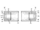
その後、外ロータ26をロータシャフト29に嵌め込んで軸方向からコアレスコイル1の両側を挟み込むように配置し、ロータシャフト29と平行に界磁束が形成される永久磁石アキシャル型回転機が組み立てられる。尚、コアレスコイル1の内側に配置される一組の永久磁石58は、ヨーク74を介して同極同士を背中合わせに貼着され、共通の1枚の内ロータプレート73に取り付けられるようにしている。なお、外ロータ26は、永久磁石59と、ヨーク76と外ロータプレート75に依って構成されている。   Thereafter, the outer rotor 26 is fitted into the rotor shaft 29 and arranged so as to sandwich both sides of the coreless coil 1 from the axial direction, and a permanent magnet axial type rotating machine in which a field flux is formed parallel to the rotor shaft 29 is assembled. The pair of permanent magnets 58 arranged inside the coreless coil 1 are attached to the common inner rotor plate 73 by attaching the same poles back to back via a yoke 74. . The outer rotor 26 includes a permanent magnet 59, a yoke 76, and an outer rotor plate 75.

コアレスコイル1の配線は、例えば図16に示すコアレスコイル1と同様に、隣合うセパレートコイルの巻き終りと巻始めとが順次電気的に接続されて、コアレスコイル1としての巻始めから巻き終りまでが1本のコイルとされている。また、複数本例えば4〜8本の導体を1つの溝に入れて巻線して成るコアレスコイル1とする場合には、コイル巻始めと巻き終りとの端末を利用して複数本の導体をシリーズに接続したり、パラレルに接続したりすることができる。   For the wiring of the coreless coil 1, for example, as in the coreless coil 1 shown in FIG. 16, the winding end and the winding start of the adjacent separate coils are electrically connected in sequence, from the winding start to the winding end as the coreless coil 1. Is a single coil. Further, when the coreless coil 1 is formed by winding a plurality of conductors, for example, 4 to 8 conductors in one groove, the plurality of conductors are connected by using terminals at the beginning and end of winding of the coil. Can be connected to a series or connected in parallel.

アキシャル型2極単相交流発電機において、外ロータ磁石59は、図24,26,28に示すように、例えば上半分側にN極が、下半分側にS極が配置されている。他方、内ロータ磁石58は、上半分側にS極が、下半分側にN極が配置されている。本実施形態の場合は、外ロータ26と内ロータ25とにそれぞれ磁石が取り付けられているが、片側が磁石でもう一方は界磁ヨークで構成するようにしても良い。   In the axial type two-pole single-phase AC generator, the outer rotor magnet 59 has, for example, an N pole on the upper half side and an S pole on the lower half side, as shown in FIGS. On the other hand, the inner rotor magnet 58 has an S pole on the upper half side and an N pole on the lower half side. In the present embodiment, magnets are attached to the outer rotor 26 and the inner rotor 25, respectively, but one side may be a magnet and the other may be a field yoke.

この2極単相交流発電機によれば、ワイヤを巻いて永久磁石を包み込む円環状箱形のコアレスコイル1を構成することができるので、1つの内ロータ25でツインアキシャル型回転機を構成することができる。しかも、外ロータ26の永久磁石59の内側のスペースを利用して軸方向に膨れた内側渡り線部4iが収められる。このため、2つのディスク型コアレスコイルを2組みのロータ磁石で挟む構造のツインアキシャル型回転機を構成する場合に比べて、薄型化・軽量化を可能とする。また、内ロータ25を囲む円環状の箱形コアレスコイル1とすることで両端支持可能で且つ機械的強度が高くなるので、太い線が巻け、プリント基板にエッチングによりコイルを形成したディスク型コアレスコイルよりも流れる電流を大きくすることができる。しかも、必要最小限のギャップにすることができるので、鎖交する磁束密度の減少が少なくなる(結果として磁束密度が大きくなり)。したがって、高出力を可能とする。   According to this two-pole single-phase AC generator, an annular box-shaped coreless coil 1 that wraps a wire and encloses a permanent magnet can be formed, and therefore, a single axial rotor 25 is formed by one inner rotor 25. be able to. Moreover, the inner connecting wire portion 4i swelled in the axial direction is accommodated using the space inside the permanent magnet 59 of the outer rotor 26. For this reason, compared with the case where the twin axial type rotary machine of the structure which pinches | interposes two disk type | mold coreless coils with two sets of rotor magnets is attained, thickness reduction and weight reduction are attained. In addition, since the annular box-shaped coreless coil 1 surrounding the inner rotor 25 can be supported at both ends and the mechanical strength is increased, a disk-shaped coreless coil in which a thick wire is wound and a coil is formed by etching on a printed board. The flowing current can be increased. In addition, since the gap can be made the minimum necessary, the decrease of the interlinkage magnetic flux density is reduced (as a result, the magnetic flux density is increased). Therefore, high output is possible.

尚、図示していないが、本実施形態のアキシャル型コアレスコイル1は、図18及び図19に示すラジアル型4極三相交流発電機に適用した実施形態と同様に、各セパレートコイル2の間の結線の組み合わせ並びに磁石の配置の変更によって、アキシャル型4極三相交流発電機としても容易に構成できる。   Although not shown, the axial coreless coil 1 of the present embodiment is provided between the separate coils 2 as in the embodiment applied to the radial type four-pole three-phase AC generator shown in FIGS. It can be easily configured as an axial type four-pole three-phase AC generator by changing the combination of the connections and the arrangement of the magnets.

また、図26〜図27に本発明にかかるコアレスコイル1を適用したアキシャル型永久磁石回転機の他の実施形態を示す。このアキシャル型永久磁石回転機は、コアレスコイル1の外側に対向配置される2組の永久磁石59を1枚の外ロータプレート75で支持するようにしたものである。この外ロータプレート75は、外周側で軸方向に折り曲げられ、コアレスコイル1を跨いでコイル1の反対側の側面に沿って先端側が径方向内側に向けて折り曲げられることによって軸方向において対向する2つの面を有し、対向した2面の内側の面に永久磁石59がのそれぞれ固着されている。したがって、コアレスコイル1の周りでは、軸方向に対向配置された外側の永久磁石59と内側の永久磁石58とが、ロータシャフト29と直交する面56に沿って各磁束鎖交部3,3を挟んで回転する。 FIGS. 26 to 27 show other embodiments of an axial permanent magnet rotating machine to which the coreless coil 1 according to the present invention is applied. This axial type permanent magnet rotating machine is configured such that two sets of permanent magnets 59 opposed to the outside of the coreless coil 1 are supported by a single outer rotor plate 75. The outer rotor plate 75 is bent in the axial direction on the outer peripheral side, and is opposed in the axial direction by bending the distal end side inward in the radial direction along the opposite side surface of the coil 1 across the coreless coil 1. The permanent magnets 59 are fixed to the inner surfaces of the two opposing surfaces. Therefore, around the coreless coil 1, the outer permanent magnet 59 and the inner permanent magnet 58 that are arranged opposite to each other in the axial direction are connected to the magnetic flux linkage portions 3 N , 3 along the surface 56 orthogonal to the rotor shaft 29. Rotate across S.

この実施形態におけるコアレスコイル1の連結並びに支持は、例えば、各々のコイルケース61A,61B,61Cの外側渡り線部4oが配置される外周縁部に設けられた固定用軸部65のボルト通し孔66に締結用ボルト68を通して、環状あるいは円弧状(半円状)の連結板84を介して相互に連結される。他方、各セパレートコイル2A,2B,2C・コイルケース61A,61B,61Cの内周側では、コアレスコイル1・コイルケース61A,61B,61Cの内側に挿入され圧入あるいは接着などでスリーブ部分80aが固定されるフランジ付きスリーブ80を備え、フランジ部分80bをコイル固定プレート30にボルト68などでねじ止めするようにしても良い。この場合にも、ロータシャフト29とスリーブ部分80bとの間にはラジアルベアリング78が介在されることが好ましい。尚、符号81はねじ孔である。   The connection and support of the coreless coil 1 in this embodiment is, for example, a bolt through hole of the fixing shaft portion 65 provided at the outer peripheral edge portion where the outer connecting wire portion 4o of each of the coil cases 61A, 61B, 61C is disposed. The coupling bolts 68 are connected to each other through an annular or arcuate (semicircular) coupling plate 84. On the other hand, on the inner peripheral side of each of the separate coils 2A, 2B, 2C and coil cases 61A, 61B, 61C, the sleeve portion 80a is fixed by being inserted into the coreless coil 1 / coil cases 61A, 61B, 61C by press-fitting or bonding. The flanged sleeve 80 may be provided, and the flange portion 80b may be screwed to the coil fixing plate 30 with a bolt 68 or the like. Also in this case, it is preferable that a radial bearing 78 is interposed between the rotor shaft 29 and the sleeve portion 80b. Reference numeral 81 denotes a screw hole.

なお、上述の形態は本発明の好適な形態の一例ではあるがこれに限定されるものではなく本発明の要旨を逸脱しない範囲において種々変形実施可能である。例えば、上述の実施形態にかかる回転機は、コアレスコイルが固定され、永久磁石による磁気回路が回転するブラシレス構造となっているが、コアレスコイルをロータシャフトで回転可能に支持したロータコイルとし、整流子を備えればブラシ付き電動機として使用できる。   The above-described embodiment is an example of a preferred embodiment of the present invention, but is not limited thereto, and various modifications can be made without departing from the scope of the present invention. For example, the rotating machine according to the above-described embodiment has a brushless structure in which a coreless coil is fixed and a magnetic circuit using a permanent magnet rotates, but the coreless coil is a rotor coil that is rotatably supported by a rotor shaft. If a child is provided, it can be used as an electric motor with a brush.

また、上述の実施形態にかかる永久磁石ラジアル型回転機では回転軸を有した駆動源から回転を入力する発電機例えば自動車エンジン用の発電機として用いることを想定しているが、ベアリングを内蔵すれば誘導機単体として使用できる。また、本発明のコアレスコイルは誘導機ばかりでなく、同期機のステータコイルあるいはロータコイルなどとしても組み込むことができる。   Further, the permanent magnet radial type rotating machine according to the above-described embodiment is assumed to be used as a generator for inputting rotation from a driving source having a rotating shaft, for example, a generator for an automobile engine. Can be used as a single induction machine. The coreless coil of the present invention can be incorporated not only as an induction machine but also as a stator coil or a rotor coil of a synchronous machine.

また、上述の実施形態においては、円環状箱形のコアレスコイル1のロータシャフト29と平行に巻かれている外周縁部分の導体(ラジアル型コアレスコイルにおいては磁束鎖交部3,3、アキシャル型コアレスコイルにおいては外側渡り線部4o)の両端で、ロータシャフト29と交わる面との成すコーナー部分の角度θが、ロータシャフト29と直交する面に沿って径方向内側に折り曲げられ、内ロータ磁石27あるいは58に跨がる軸平面形状コの字形を成すように90°に形成されているが、これに特に限られるものでなく、90°≦θ<180°の範囲内であれば良い。なかでも、コアレスコイル1のコンパクト化を図るためには、コーナー角度θは90°であることが好ましいが、エナメル構造(絶縁構造)によっては90°に折り曲げると皮膜がひび割れする可能性があるので、場合によっては緩やかな角度例えば110°〜120°の略ハの字型(即ち、〔形を90°回転させたような形態)に折り曲げられても良いし、あるいは大きな曲面を構成するようにしても良い。さらには、コアレスコイル1のロータシャフト29と平行に巻かれている外周縁部分の導体と、ロータシャフト29と直交あるいは交わる面との間に例えば120°〜150°の比較的緩やかな斜面を形成して、2段階に折れ曲がるようにして、それぞれの折れ曲がり角度が90°を超えるようにしても良い。 Further, in the above-described embodiment, flux-exchange unit 3 N in an outer peripheral edge portion of the conductor (radial type coreless coils that are parallel to wound the rotor shaft 29 of the coreless coil 1 of the annular box-shaped, 3 S, In the axial type coreless coil, the angle θ of the corner portion formed with the surface intersecting with the rotor shaft 29 at both ends of the outer connecting wire portion 4o) is bent radially inward along the surface orthogonal to the rotor shaft 29. Although it is formed at 90 ° so as to form a U-shape of an axial plane straddling the rotor magnet 27 or 58, it is not particularly limited to this, and is within the range of 90 ° ≦ θ <180 °. good. In particular, in order to make the coreless coil 1 more compact, the corner angle θ is preferably 90 °. However, depending on the enamel structure (insulating structure), the film may be cracked when bent to 90 °. Depending on circumstances, it may be bent into a generally square shape with a gentle angle, for example, 110 ° to 120 ° (ie, a shape obtained by rotating the shape by 90 °), or a large curved surface may be formed. May be. Furthermore, a relatively gentle slope of, for example, 120 ° to 150 ° is formed between the conductor at the outer peripheral edge wound in parallel with the rotor shaft 29 of the coreless coil 1 and the surface orthogonal to or intersecting with the rotor shaft 29. Then, it may be bent in two stages so that each bending angle exceeds 90 °.

また、上述の実施形態においては、内側に配置される永久磁石あるいはマグネットヨークを囲うように径方向内側に折り曲げられた導体部分(ラジアル型コアレスコイルにおいては渡り線部4、アキシャル型コアレスコイルにおいては磁束鎖交部3,3と内側渡り線部4i並びに外側渡り線部4oの一部)が同じ長さの軸平面形状コの字形を成す円環状箱形のコアレスコイルに形成されているが、これに特に限られず、一方の長さが他方の長さに比べて短い非対称な形状とされても良い。本明細書において、軸平面形状コ形とは、界磁束を構成する一方の永久磁石あるいは界磁ヨークを囲繞し円環状箱形を成すものであることを意味しており、厳密な意味で直角に折れ曲がり全く等しい長さの対称形状である必要はない。 Further, in the above-described embodiment, the conductor portion bent inward in the radial direction so as to surround the permanent magnet or the magnet yoke arranged on the inner side (in the case of the radial coreless coil, the crossover portion 4 and in the axial type coreless coil) The magnetic flux linkage portions 3 N , 3 S , the inner connecting wire portion 4 i and a part of the outer connecting wire portion 4 o are formed in an annular box-shaped coreless coil having an axial plane U-shape having the same length. However, the present invention is not particularly limited to this, and an asymmetric shape in which one length is shorter than the other length may be used. In the present specification, the axial plane shape U-shape means that one of the permanent magnets or the field yoke constituting the field magnetic flux is surrounded to form an annular box shape, and is strictly perpendicular. It is not necessary to be a symmetrical shape with a completely equal length.

また、上述の実施形態では、コアレスコイル1を二極単相永久磁石型回転機・発電機に組み込む場合を例に挙げて主に説明したが、その用途は特に限られず、多極複相のラジアル型回転機例えば六極三相交流発電機などとして構成することも可能である。また、多極回転機に応用する場合の磁石角度は、当然、極数により決定される。例えば、10極の場合は36°となる。   In the above-described embodiment, the case where the coreless coil 1 is incorporated into a two-pole single-phase permanent magnet type rotating machine / generator has been mainly described as an example. It is also possible to configure as a radial type rotating machine, for example, a six-pole three-phase AC generator. Further, the magnet angle when applied to a multipolar rotating machine is naturally determined by the number of poles. For example, in the case of 10 poles, the angle is 36 °.

また、コイルケースの形状は正面(軸方向)視形状において全て同じである必要はない。即ち、セパレートコイル2には必ずしもコイルケースの端から端まで巻かれることが無く、コイルケースの一部に導体が巻かれることもある。例えば、図示していないが、3種類の幅W,W,W(但し、W<W<W)のセパレートコイル2A,B,Cのコイルケースの周方向角度θを30°ずつ狭くして、Aは180°、Bは150°、Cは120°とすることによって、Cの領域では3つのセパレートコイル2の渡り線とコイルケースが、Bの領域では2つのセパレートコイル2の渡り線とコイルケースが、Aの領域では1つのセパレートコイル2の渡り線とコイルケースがそれぞれ配置され、それが点対称に配置されたコアレスコイル1を構成するようにしても良い。この場合においても各セパレートコイル2に巻かれたコイルの磁束が通過する外周面部分の角度は同じに形成される。即ち、各セパレートコイル2に巻かれるコイルの幅は同じで、余白(コイルが巻かれていない領域)が60°のものと、30°のものと、0のものとの3種類のセパレートコイル2となる。これによって、30°ずつずらして組み合わせることで、全体としては180°の範囲にコイルが巻かれたセパレートコイル2を構成するようにしても良い。 Further, the shape of the coil case does not have to be the same in the front (axial direction) view shape. That is, the separate coil 2 is not necessarily wound from end to end of the coil case, and a conductor may be wound around a part of the coil case. For example, although not shown, the circumferential angle θ 5 of the coil case of the separate coils 2A, B, and C having three types of widths W 1 , W 2 , and W 3 (W 1 <W 2 <W 3 ) is set. By narrowing by 30 °, A is 180 °, B is 150 °, and C is 120 °, so that the connecting wire and the coil case of the three separate coils 2 are in the region C, and two separate are in the region B. The connecting wire and the coil case of the coil 2 may be arranged in the region A, and the connecting wire and the coil case of one separate coil 2 may be arranged, and the coreless coil 1 arranged in a point symmetry may be configured. Even in this case, the angle of the outer peripheral surface portion through which the magnetic flux of the coil wound around each separate coil 2 passes is formed to be the same. That is, the width of the coil wound around each separate coil 2 is the same, and the three types of separate coils 2 have a margin (area in which no coil is wound) of 60 °, 30 °, and 0. It becomes. Accordingly, the separate coil 2 in which the coil is wound in a range of 180 ° as a whole may be configured by shifting and combining by 30 °.

1 コアレスコイル
2 セパレートコイル
2A 最も幅の狭いセパレートコイル
2B 中位の幅のセパレートコイル
2C 最も幅の広いセパレートコイル
3 磁束鎖交部
3N N極側磁束鎖交部
3S S極側磁束鎖交部
4 渡り線部
4o 外側渡り線部
4i 内側渡り線部
5,62 円弧部
7,17,60 空所(他のセパレートコイルの磁束鎖交部及び渡り線部が入る空間) 10 導体
11,61 コイルケース
19,69 導体ガイド溝
20,70 磁束鎖交部溝領域(コイル位置決め溝を構成する)
21 渡り線溝領域(コイル位置決め溝を構成する)
71o 外側渡り線溝領域(コイル位置決め溝を構成する)
71i 内側渡り線溝領域(コイル位置決め溝を構成する)
25 内ロータ
26 外ロータ
27,58 内ロータ永久磁石
28,59 外ロータ永久磁石
29 メータシャフト
1 Coreless coil
2 Separation coil 2A Narrowest separation coil 2B Middle width separation coil 2C Widest separation coil 3 Magnetic flux linkage 3N N pole side magnetic flux linkage 3S S pole side magnetic flux linkage 4 Crossover part 4o Outer connecting wire portion 4i Inner connecting wire portion 5, 62 Arc portion 7, 17, 60 Empty space (space where magnetic flux linkage portion and connecting wire portion of other separate coils enter) 10 Conductor 11, 61 Coil case 19, 69 Conductor guide groove 20, 70 Magnetic flux interlinkage groove region (constitutes a coil positioning groove)
21 Crossover groove area (constitutes coil positioning groove)
71o Outside crossover groove region (constitutes coil positioning groove)
71i Inner crossover groove region (configures coil positioning groove)
25 Inner rotor 26 Outer rotor 27, 58 Inner rotor permanent magnet 28, 59 Outer rotor permanent magnet 29 Meter shaft

Claims (12)

周方向に少なくとも2分割され、機械角で180°以下に分割された複数のセパレートコイルによって構成され、
前記各セパレートコイルは、永久磁石のN極側に対応する磁束鎖交部と、永久磁石のS極側に対応する磁束鎖交部と、前記N極側磁束鎖交部と前記S極側磁束鎖交部の導体を繋ぐ渡り線部とを有し、
複数の前記セパレートコイルを周方向に連結することによって、軸平面形状コ形のコイルを構成する
ことを特徴とするコアレスコイル。
It is composed of a plurality of separate coils divided into at least two in the circumferential direction and divided into mechanical angles of 180 ° or less,
Each of the separate coils includes a magnetic flux linkage portion corresponding to the N pole side of the permanent magnet, a magnetic flux linkage portion corresponding to the S pole side of the permanent magnet, the N pole side magnetic flux linkage portion, and the S pole side magnetic flux. A crossover connecting the conductors of the interlinkage,
A coreless coil, wherein a plurality of the separate coils are connected in the circumferential direction to constitute an axial plane U-shaped coil.
前記セパレートコイルは、周方向にずらして互いに入り込ませがら組み合わせる入れ子構造にしたことを特徴とする請求項1記載のコアレスコイル。 The coreless coil according to claim 1, wherein the separate coils have a nested structure that is combined while being shifted in the circumferential direction. 前記セパレートコイルには、該コイルを構成する導体を内側から支持して固定するコイルケースを備えることを特徴とする請求項1または2記載のコアレスコイル。 The coreless coil according to claim 1, wherein the separate coil includes a coil case that supports and fixes a conductor constituting the coil from the inside. 前記セパレートコイルは、内周側にロータシャフトが貫通する円弧部を有し、かつ前記ロータシャフトと平行に巻かれている外周縁部分の導体によって前記ロータシャフトの径方向に形成される界磁束が通過する前記磁束鎖交部を構成し、前記渡り線部がロータシャフトと直交する面に沿って前記磁束鎖交部の導体の両端で径方向内側に折り曲げられかつ周方向に引き回されて前記ロータシャフト周辺を迂回し、前記磁束鎖交部と前記渡り線部とが軸平面でコの字形を成すものであることを特徴とする請求項1から3のいずれか1つに記載のコアレスコイル。 The separate coil has an arc portion through which the rotor shaft passes on the inner peripheral side, and a field magnetic flux formed in a radial direction of the rotor shaft by a conductor in an outer peripheral portion wound in parallel with the rotor shaft. The magnetic flux linkage part that passes through is formed, the crossover part is bent radially inward at both ends of the conductor of the magnetic flux linkage part along a plane orthogonal to the rotor shaft, and is routed in the circumferential direction. The coreless coil according to any one of claims 1 to 3, wherein the coreless coil bypasses the periphery of the rotor shaft, and the magnetic flux linkage portion and the crossover portion form a U-shape in an axial plane. . 前記セパレートコイルは、内周側にロータシャフトが貫通する円弧部を有し、かつ前記ロータシャフトと平行な界磁束が通過する前記N極側磁束鎖交部と前記S極側磁束鎖交部とがロータシャフトと直交する2つの面のそれぞれに形成され、かつこれらN極側磁束鎖交部とS極側磁束鎖交部の導体を繋ぐ前記渡り線部が前記N極側磁束鎖交部と前記S極側磁束鎖交部の径方向内側で前記ロータシャフトと交わる面に沿って求心方向並びに周方向に引き回されて前記ロータシャフトの周辺を迂回するように配線される内側渡り線部と、前記N極側磁束鎖交部と前記S極側磁束鎖交部の径方向外側で内ロータ磁石に跨がるような軸平面形状コの字形に形成されている外側渡り線部とによって構成されていることを特徴とする請求項1から3のいずれか1つに記載のコアレスコイル。 The separate coil has an arc portion through which the rotor shaft passes on the inner peripheral side, and the N pole side flux linkage portion and the S pole side flux linkage portion through which a field flux parallel to the rotor shaft passes. Are formed on each of two surfaces orthogonal to the rotor shaft, and the crossover portion connecting the conductors of the N pole side magnetic flux linkage portion and the S pole side magnetic flux linkage portion is formed with the N pole side magnetic flux linkage portion. An inner connecting wire portion that is routed in a centripetal direction and a circumferential direction along a surface intersecting with the rotor shaft on the radially inner side of the S pole side magnetic flux linkage portion and is routed so as to bypass the periphery of the rotor shaft; And an outer crossover portion formed in an axial plane U-shape that straddles the inner rotor magnet on the radially outer side of the N pole side magnetic flux linkage portion and the S pole side magnetic flux linkage portion. Any of claims 1 to 3, characterized in that Coreless coil according to one or. 前記コイルケースは、前記N極側磁束鎖交部及び前記S極側磁束鎖交部を収容する磁束鎖交部溝領域と、前記渡り線が収容される渡り線溝領域とを有するコイル位置決め溝を備えるものであり、予め巻回された前記セパレートコイルを前記コイル位置決め溝に嵌め込んで固定することを特徴とする請求項1から5のいずれか1つに記載のコアレスコイル。 The coil case includes a magnetic flux linkage groove region that accommodates the N pole side magnetic flux linkage portion and the S pole side magnetic flux linkage portion, and a crossover groove region that accommodates the jumper wire. The coreless coil according to any one of claims 1 to 5, wherein the separate coil wound in advance is fitted into the coil positioning groove and fixed. 前記コイルケースは、導体を巻回するための位置を導く複数本の導体ガイド溝によって、前記N極側磁束鎖交部及び前記S極側磁束鎖交部を収める磁束鎖交部溝領域と、前記渡り線を収める渡り線溝領域とを有するコイル位置決め溝を備えるものであり、前記導体を前記導体ガイド溝に沿って押し込むように巻き付けることによって当該コイルケースを巻芯として前記セパレートコイルが巻回されることを特徴とする請求項1から5のいずれか1つに記載のコアレスコイル。 The coil case has a magnetic flux linkage groove region for accommodating the N pole side magnetic flux linkage and the S pole side magnetic flux linkage by a plurality of conductor guide grooves that guide a position for winding the conductor; A coil positioning groove having a connecting wire groove region for accommodating the connecting wire, and the separate coil is wound around the coil case by winding the conductor so as to be pushed along the conductor guide groove. The coreless coil according to any one of claims 1 to 5, wherein the coreless coil is formed. 前記セパレートコイルには、複数の前記セパレートコイルを相互に周方向に組み合わせて連結するための締結用ボルトを通す孔あるいはねじ孔を前記渡り線部の配線の間あるいは配線の外の領域に設けることを特徴とする請求項1から7のいずれか1つに記載のコアレスコイル。 The separate coil is provided with a hole or a screw hole through which a fastening bolt for connecting a plurality of the separate coils in a circumferential direction is connected to each other or in an area outside the wiring. The coreless coil according to claim 1, wherein: 前記セパレートコイルを構成する前記導体は複数本であり、これら複数本の導体をコイル巻始めと巻き終りとの端末を利用して並列あるいは直列接続可能とする請求項1から8のいずれか1つに記載のコアレスコイル。 The said conductor which comprises the said separate coil is two or more, These one or more conductors can be connected in parallel or in series using terminals of the coil winding start and winding end. The coreless coil described in 1. 内周側にロータシャフトが貫通する円弧部を有し、かつ導体を巻回するための位置を導く複数本の導体ガイド溝によってN極側磁束鎖交部及びS極側磁束鎖交部を収める磁束鎖交部溝領域と渡り線を収める渡り線溝領域とを形成するコイル位置決め溝を構成しかつ機械角で180°以下の扇形を成す軸平面形状コ形のコイルケースを巻心とし、前記導体を前記導体ガイド溝に沿って押し込みながら前記導体ガイド溝に沿って巻き付けることによって前記N極側磁束鎖交部と前記S極側磁束鎖交部及びこれらを繋ぐ前記渡り線部を巻回することを特徴とするセパレートコイルの製造方法。 The N pole side magnetic flux linkage part and the S pole side magnetic flux linkage part are accommodated by a plurality of conductor guide grooves having a circular arc part through which the rotor shaft passes on the inner peripheral side and guiding a position for winding the conductor. The coil positioning groove forming the magnetic flux linkage groove region and the connecting wire groove region for accommodating the connecting wire is configured, and the axial planar U-shaped coil case forming a fan shape with a mechanical angle of 180 ° or less is used as the winding core, By winding the conductor along the conductor guide groove while pushing the conductor along the conductor guide groove, the N pole side magnetic flux linkage part and the S pole side magnetic flux linkage part and the connecting wire part connecting them are wound. The manufacturing method of the separate coil characterized by the above-mentioned. 請求項1から9のいずれか1つに記載のコアレスコイルをステータコイルあるいはロータコイルとして用いることを特徴とする永久磁石型回転機。 A permanent magnet type rotating machine using the coreless coil according to any one of claims 1 to 9 as a stator coil or a rotor coil. ステータコイルと、前記ステータコイルの外側に位置する外ロータ磁石と前記ステータコイルの内側に位置する内ロータ磁石とを有する永久磁石型回転機において、請求項1から8のいずれか1つに記載のコアレスコイルを構成する複数の前記セパレートコイルを前記内マグネットロータを挟んで組み合わせて周方向に連結することによって前記内マグネットロータを囲む中が空洞の円環状箱形のステータコイルを構成し、その後外マグネットロータを軸方向から挿入して前記ステータコイルの外側に配置させることにより組み立てることを特徴とする永久磁石型回転機の製造方法。 The permanent magnet type rotating machine having a stator coil, an outer rotor magnet located outside the stator coil, and an inner rotor magnet located inside the stator coil, according to any one of claims 1 to 8. A plurality of the separate coils constituting the coreless coil are combined with the inner magnet rotor interposed therebetween and connected in the circumferential direction, thereby forming an annular box-shaped stator coil having a hollow inside surrounding the inner magnet rotor, and then the outer coil A method of manufacturing a permanent magnet type rotating machine, comprising assembling a magnet rotor inserted from an axial direction and disposed outside the stator coil.
JP2014264497A 2014-12-26 2014-12-26 Coreless coil and manufacturing method for the same, and permanent magnet type rotary machine and manufacturing method for the same Pending JP2016127628A (en)

Priority Applications (1)

Application Number Priority Date Filing Date Title
JP2014264497A JP2016127628A (en) 2014-12-26 2014-12-26 Coreless coil and manufacturing method for the same, and permanent magnet type rotary machine and manufacturing method for the same

Applications Claiming Priority (1)

Application Number Priority Date Filing Date Title
JP2014264497A JP2016127628A (en) 2014-12-26 2014-12-26 Coreless coil and manufacturing method for the same, and permanent magnet type rotary machine and manufacturing method for the same

Publications (1)

Publication Number Publication Date
JP2016127628A true JP2016127628A (en) 2016-07-11

Family

ID=56359969

Family Applications (1)

Application Number Title Priority Date Filing Date
JP2014264497A Pending JP2016127628A (en) 2014-12-26 2014-12-26 Coreless coil and manufacturing method for the same, and permanent magnet type rotary machine and manufacturing method for the same

Country Status (1)

Country Link
JP (1) JP2016127628A (en)

Cited By (3)

* Cited by examiner, † Cited by third party
Publication number Priority date Publication date Assignee Title
JP2019531046A (en) * 2016-09-29 2019-10-24 ダブリュー ギャブリース クリストファー Motor generator assembly process
JP2020013810A (en) * 2018-07-13 2020-01-23 昭和電線ケーブルシステム株式会社 Non-contact power supply device, coil, and manufacturing method of coil
WO2020213651A1 (en) * 2019-04-19 2020-10-22 株式会社デンソー Rotating electric machine

Cited By (6)

* Cited by examiner, † Cited by third party
Publication number Priority date Publication date Assignee Title
JP2019531046A (en) * 2016-09-29 2019-10-24 ダブリュー ギャブリース クリストファー Motor generator assembly process
JP7282443B2 (en) 2016-09-29 2023-05-29 ダブリュー ギャブリース クリストファー Assembly method of brushless motor generator
JP2020013810A (en) * 2018-07-13 2020-01-23 昭和電線ケーブルシステム株式会社 Non-contact power supply device, coil, and manufacturing method of coil
JP7199170B2 (en) 2018-07-13 2023-01-05 昭和電線ケーブルシステム株式会社 Contactless power supply device, coil, and method for manufacturing coil
WO2020213651A1 (en) * 2019-04-19 2020-10-22 株式会社デンソー Rotating electric machine
CN113711470A (en) * 2019-04-19 2021-11-26 株式会社电装 Rotating electrical machine

Similar Documents

Publication Publication Date Title
JP6977556B2 (en) Rotating machine
US7737598B2 (en) Electric motor having a stator
JP6068953B2 (en) Electric motor
WO2015060058A1 (en) Bus bar unit and motor
US10298084B2 (en) Rotating electric machine for vehicle
JP4735210B2 (en) motor
JP2009022088A (en) Rotary electric machine and its manufacturing method
JP2003009443A (en) Rotary electric machine stator having detachable individual coil
JP2010239740A (en) Armature for rotating electric machine
JP6626514B2 (en) Rotating electric machine
JP2001333555A (en) Slot-less radial gap motor
JP7496185B2 (en) Busbar Unit
JP2016127628A (en) Coreless coil and manufacturing method for the same, and permanent magnet type rotary machine and manufacturing method for the same
WO2011148501A1 (en) Stator
TW201742356A (en) Axial gap type rotary electric machine
JP2005124378A (en) Induction motor having annular stator coil
JP2003333811A (en) Induction motor having a plurality of axially divided stator windings
JP2009095070A (en) Rotary electric motor
JP2010239741A (en) Armature for rotating electric machine
JP2010239680A (en) Armature for rotary electric machine and manufacturing method therefor
WO2014103758A1 (en) Rotary machine and stator manufacturing method
JP2021090277A (en) Rotary electric machine
WO2024162233A1 (en) Motor and coil winding method
JP5657907B2 (en) Electric motor and coil winding method
JP2007306745A (en) Polyphase motor