JP2016123789A - Obstacle nail, ball game machine, and method of manufacturing obstruction nail - Google Patents
Obstacle nail, ball game machine, and method of manufacturing obstruction nail Download PDFInfo
- Publication number
- JP2016123789A JP2016123789A JP2015001882A JP2015001882A JP2016123789A JP 2016123789 A JP2016123789 A JP 2016123789A JP 2015001882 A JP2015001882 A JP 2015001882A JP 2015001882 A JP2015001882 A JP 2015001882A JP 2016123789 A JP2016123789 A JP 2016123789A
- Authority
- JP
- Japan
- Prior art keywords
- axial direction
- obstacle nail
- value
- radial dimension
- tip
- Prior art date
- Legal status (The legal status is an assumption and is not a legal conclusion. Google has not performed a legal analysis and makes no representation as to the accuracy of the status listed.)
- Granted
Links
Images
Landscapes
- Pinball Game Machines (AREA)
Abstract
Description
本発明は、弾球遊技機の障害釘、弾球遊技機及び障害釘の製造方法に関する。 The present invention relates to an obstacle nail for a ball game machine, a ball game machine, and a method for manufacturing the obstacle nail.
弾球遊技機の障害釘に関する技術が提案されている。例えば、出願人は、特許文献1、特許文献2及び特許文献3において、弾球遊技機用釘を提案している。弾球遊技機は、パチンコ機等である。
Techniques for obstacle nails in ball game machines have been proposed. For example, the applicant has proposed a nail for a ball game machine in Patent Document 1, Patent Document 2, and
特許文献1の弾球遊技機用釘は、頭部と軸部を備える。軸部は、頭部に加えられた打ち込み力によって、合成樹脂等からなる遊技盤に形成された下穴に挿入される。弾球遊技機用釘は、遊技球の流路を形成する。軸部は、テーパ部と、螺旋部と、第一ストレート部と、第二ストレート部を備える。これら各部分は、釘の先端部から基端部(頭部との境界部)に向けて、テーパ部、第二ストレート部、螺旋部、第一ストレート部の順に形成される。テーパ部は、先端に向けて漸次先細りする。螺旋部は、円柱体の外周面に螺旋を有する。螺旋の山頂幅は、先端において狭く、基端において広くなるようにされる。第二ストレート部の径は、テーパ部の基端径と同じとされる。このように形成された第二ストレート部は、下穴に沿って挿入された釘を垂直に案内するガイド機能を発揮する。釘を確実に下穴に沿って垂直に且つスムーズに打ち込むことが可能となる。第一ストレート部には、螺旋部寄りの部分に、環状溝が形成される。 The nail for a ball ball game machine of Patent Document 1 includes a head portion and a shaft portion. The shaft portion is inserted into a pilot hole formed in a game board made of synthetic resin or the like by a driving force applied to the head portion. The nail for a ball game machine forms a flow path for a game ball. The shaft portion includes a taper portion, a spiral portion, a first straight portion, and a second straight portion. Each of these portions is formed in the order of a tapered portion, a second straight portion, a spiral portion, and a first straight portion from the tip end portion of the nail toward the base end portion (boundary portion with the head portion). The taper portion gradually tapers toward the tip. The spiral portion has a spiral on the outer peripheral surface of the cylindrical body. The peak width of the helix is narrow at the tip and wide at the base. The diameter of the second straight portion is the same as the proximal end diameter of the tapered portion. The second straight portion formed in this manner exhibits a guide function for vertically guiding the nail inserted along the pilot hole. It is possible to reliably drive the nail vertically and smoothly along the pilot hole. An annular groove is formed in the first straight portion at a portion near the spiral portion.
特許文献2の弾球遊技機用釘は、頭部と軸部を備える。軸部は、先端に向けて先細りとなるテーパ部を有する。テーパ部は、密接部と、食い込み部を有する。密接部は、基端部と先端部に設けられる。密接部は、弾球遊技機の基盤に形成されたテーパ孔の内面に密接する。食い込み部は、基端部と先端部の間に設けられる。食い込み部は、テーパ孔の内面に食い込む。食い込み部は、第一の円錐台状部と第二の円錐台状部を軸方向に交互に備え。第一の円錐台状部は、先端に向けてテーパ孔と略同じ傾きをもって縮径する。第二の円錐台状部は、先端に向けてテーパ孔よりも大きい傾きをもって縮径する。別の形態として、食い込み部は、螺旋状に形成された突条を備える。突条の一部分には、略V字状の切欠が形成される。 The nail for a ball game machine of Patent Document 2 includes a head portion and a shaft portion. The shaft portion has a tapered portion that tapers toward the tip. The taper portion has a close contact portion and a biting portion. The close contact portion is provided at the proximal end portion and the distal end portion. The close contact portion is in close contact with the inner surface of the tapered hole formed in the base of the ball game machine. The biting portion is provided between the proximal end portion and the distal end portion. The biting portion bites into the inner surface of the tapered hole. The biting portion includes first frustoconical portions and second frustoconical portions alternately in the axial direction. The first frustoconical portion is reduced in diameter toward the tip with substantially the same inclination as the tapered hole. The second frustoconical portion is reduced in diameter toward the tip with a larger inclination than the tapered hole. As another form, the biting portion includes a ridge formed in a spiral shape. A substantially V-shaped notch is formed in a part of the ridge.
特許文献3の弾球遊技機用釘は、頭部と軸部を備える。軸部は、非螺旋部と、螺旋部を有する。非螺施部は、基端側に設けられる。非螺施部は、螺旋の無い部分である。螺旋部は、先端側に設けられる。螺旋部は、外周面に螺旋が形成された部分である。螺旋部の山条には、複数のV字状切込みが形成されている。
The nail for a ball game machine of
この他、出願人は、特許文献4で、弾球遊技機の障害釘に関する技術を提案している。この障害釘では、軸部は、弾球衝突部と先端部の間に中間部を有する。中間部は、弾球衝突部の外径以下の径で、且つ弾球衝突部より高硬度とされる。 In addition to this, the applicant has proposed a technique related to the obstacle nail of the ball game machine in Patent Document 4. In this obstacle nail, the shaft portion has an intermediate portion between the bullet impact portion and the tip portion. The intermediate portion has a diameter equal to or smaller than the outer diameter of the bullet ball collision portion and is harder than the bullet ball collision portion.
パチンコ機等の弾球遊技機では、障害釘を遊技盤に精度よく配列し固定することが求められることがある。遊技盤は、例えば、木製又は樹脂製のものがある。遊技盤が木製である場合、障害釘は、直接、障害釘が遊技盤に取り付けられることがある。障害釘の遊技盤への取り付けは、例えば、障害釘の頭部に衝撃を与え、障害釘を遊技盤に打ち込み行われる。この場合、障害釘の位置ずれが生じることがある。遊技盤が樹脂製である場合、遊技盤には穴部が形成されることがある。これは、遊技盤を形成する樹脂が高硬度であることに起因する。即ち、障害釘を直接樹脂製の遊技盤に打ち込むと、障害釘の軸部が変形するためである。障害釘が、高硬度の樹脂製の遊技盤に打ち込まれないこともある。樹脂製の遊技盤においては、穴部を形成することで、障害釘を、穴部の内周に沿わせつつ、穴部に挿入することができる。その結果、障害釘は、遊技盤に精度よく配列され、固定され易くなる。そこで、発明者は、遊技盤の材質に関わらず、遊技盤に障害釘を固定する穴部が形成された場合に、障害釘を精度よく配列させ、固定させ易くすることができる技術について検討を行った。 In a ball game machine such as a pachinko machine, it may be required to accurately arrange and fix the obstacle nail on the game board. The game board is, for example, made of wood or resin. When the game board is wooden, the obstacle nail may be directly attached to the game board. For example, the obstacle nail is attached to the game board by impacting the head of the obstacle nail and driving the obstacle nail into the game board. In this case, a position shift of the obstacle nail may occur. When the game board is made of resin, a hole may be formed in the game board. This is due to the high hardness of the resin forming the game board. That is, when the obstacle nail is directly driven into the resin game board, the shaft portion of the obstacle nail is deformed. The obstruction nail may not be driven into a high-hardness resin game board. In the resin game board, by forming the hole portion, the obstacle nail can be inserted into the hole portion along the inner periphery of the hole portion. As a result, the obstacle nails are arranged on the game board with high accuracy and are easily fixed. Therefore, the inventor examined a technology that can easily arrange and fix the obstacle nails with high accuracy when the hole for fixing the obstacle nail is formed on the game board regardless of the material of the game board. went.
本発明は、弾球遊技機の遊技盤の材質に関わらず、障害釘を遊技盤に精度よく配列し固定することができる技術を提供することを目的とする。 An object of the present invention is to provide a technology that can accurately arrange and fix obstacle nails on a game board regardless of the material of the game board of the ball game machine.
本発明の一側面は、頭部と、前記頭部と一体をなす軸部と、を備える、弾球遊技機の障害釘であって、前記頭部は、前記障害釘の軸心に沿った軸方向の第一側とは反対側となる前記軸方向の第二側における前記障害釘の端部に設けられ、前記軸部は、前記軸方向の第二側から第一側に向けて先細りした形状を有し、前記軸方向の第一側における前記障害釘の端部に設けられる先端部と、前記軸方向に直交する径方向の寸法が第一値である円柱形状を有し、前記先端部と前記頭部との間に設けられる弾球衝突部と、前記径方向の寸法が、前記軸方向の第二側における前記先端部の端部の前記径方向の寸法に一致する第二値である円柱形状を有し、前記先端部と前記弾球衝突部との間に設けられるガイド部と、環状の溝部と、前記径方向の寸法が前記第一値より大きい環状の隆起部と、によって形成され、前記ガイド部と前記弾球衝突部との間に設けられる突出部と、前記軸方向の第二側から第一側に向けて先細りした形状を有し、先細り端部の前記径方向の寸法が前記第二値で、前記ガイド部と前記突出部との間に設けられる第一拡大部と、を備える、障害釘である。 One aspect of the present invention is an obstruction nail for a ball game machine comprising a head and a shaft portion integral with the head, the head being along the axis of the obstruction nail. Provided at an end of the obstruction nail on the second axial side opposite to the first axial side, and the axial portion tapers from the second axial side toward the first side. A cylindrical shape whose first dimension is a radial dimension orthogonal to the axial direction, and a tip provided at an end of the obstacle nail on the first side in the axial direction, A second ball colliding part provided between the tip part and the head part, and the radial dimension coincides with the radial dimension of the end part of the tip part on the second side in the axial direction. A cylindrical shape that is a value, a guide portion provided between the tip portion and the bullet impact portion, an annular groove portion, and the radial dimension are A projecting portion formed between the guide portion and the bullet impact portion, and tapered from the second side in the axial direction toward the first side. And a first enlarged portion provided between the guide portion and the projecting portion. The obstacle nail has a shape that has the shape described above, and the radial dimension of the tapered end portion is the second value.
これによれば、遊技盤に形成する穴部を、円柱形状のガイド部の径方向の寸法に対応させた寸法の穴とすることで、先端部が穴部に挿入された後、障害釘は、ガイド部の外周が穴部の内周に倣った状態となる。その結果、障害釘は、ガイド部によって穴部の内周にガイドされる。ガイド部をスムーズに穴部に挿入することができる。そのため、取り付け途中の障害釘を、障害釘の軸心と穴部の軸心を一致させた状態で、遊技盤に支持することができる。その後、第一拡大部が穴部に挿入されることとなる。第一拡大部を、軸方向の第二側から第一側に向けて先細りした形状とすることで、第一拡大部を穴部に挿入する際の挿入荷重の急激な増加を抑制しつつ、穴部を径方向に拡大させ、その後、突出部の挿入へと移行することができる。障害釘の遊技盤へのスムーズな取り付けを実現することができる。取り付けが完了した状態において、第一拡大部は、穴部に圧入状態となり、突出部は、穴部の内周に押し込まれた状態となる。突出部と第一拡大部によって、遊技盤からの障害釘の抜けに対する抗力を向上させることができる。 According to this, the hole formed in the game board is a hole having a dimension corresponding to the dimension in the radial direction of the cylindrical guide part, so that the obstacle nail is inserted after the tip part is inserted into the hole. The outer periphery of the guide part follows the inner periphery of the hole part. As a result, the obstacle nail is guided to the inner periphery of the hole portion by the guide portion. The guide portion can be smoothly inserted into the hole portion. Therefore, the obstacle nail being attached can be supported on the game board in a state where the axis of the obstacle nail is aligned with the axis of the hole. Thereafter, the first enlarged portion is inserted into the hole. By making the first enlarged portion tapered from the second side in the axial direction toward the first side, while suppressing a sudden increase in insertion load when inserting the first enlarged portion into the hole, The hole can be enlarged in the radial direction, and then the process can proceed to insertion of the protrusion. Smooth attachment of the obstacle nail to the game board can be realized. In a state where the attachment is completed, the first enlarged portion is press-fitted into the hole, and the protruding portion is pushed into the inner periphery of the hole. By the protrusion and the first enlarged portion, it is possible to improve the resistance against the removal of the obstacle nail from the game board.
軸方向の第二側における先端部の端部について、先端部の形状が円錐又は円錐台である場合、この部分の径方向の寸法は、円錐又は円錐台の底面の外径である。隆起部について、隆起部の形状が円環状である場合、径方向の寸法は、隆起部の外径である。第一拡大部の先細り端部について、第一拡大部の形状が円錐台である場合、この部分の径方向の寸法は、円錐台の天面の外径である。弾球衝突部の径方向の寸法は、弾球衝突部の外径である。ガイド部の径方向の寸法は、ガイド部の外径である。 Regarding the end of the tip on the second side in the axial direction, when the shape of the tip is a cone or a truncated cone, the radial dimension of this portion is the outer diameter of the bottom surface of the cone or the truncated cone. When the shape of the raised portion is an annular shape, the dimension in the radial direction is the outer diameter of the raised portion. Regarding the tapered end portion of the first enlarged portion, when the shape of the first enlarged portion is a truncated cone, the radial dimension of this portion is the outer diameter of the top surface of the truncated cone. The dimension in the radial direction of the bullet ball collision part is the outer diameter of the bullet ball collision part. The radial dimension of the guide part is the outer diameter of the guide part.
障害釘において、前記ガイド部は、前記径方向の寸法が前記第一値より小さい前記第二値である円柱形状を有し、前記第一拡大部は、前記障害釘の軸心に対する傾斜角が第一角度で、前記軸方向の第二側から第一側に向けて先細りした形状を有し、ローレット目が外周に形成され、前記径方向の寸法が前記第一値より大きい第一ローレット部と、前記障害釘の軸心に対する傾斜角が前記第一角度より大きい第二角度で、前記軸方向の第二側から第一側に向けて先細りした形状を有し、先細り端部の前記径方向の寸法が前記第二値で、前記軸方向の第一側で、前記軸方向の第二側における前記ガイド部の端部と隣接し、且つ前記軸方向の第二側で、前記軸方向の第一側における前記第一ローレット部の端部と隣接する第一境界部と、を備える、ようにしてもよい。この場合、前記第一ローレット部には、螺旋状の凹部と、螺旋状の凸部と、による前記ローレット目が外周に形成されている、ようにしてもよい。 In the obstacle nail, the guide portion has a cylindrical shape whose second dimension is smaller than the first value, and the first enlarged portion has an inclination angle with respect to the axis of the obstacle nail. A first knurl portion having a first angle and a shape tapered from the second side in the axial direction toward the first side, knurled eyes are formed on the outer periphery, and the radial dimension is larger than the first value. And an inclination angle with respect to the axis of the obstacle nail is a second angle larger than the first angle, and has a shape tapered from the second side in the axial direction toward the first side, and the diameter of the tapered end portion The dimension in the direction is the second value, on the first side in the axial direction, adjacent to the end of the guide portion on the second side in the axial direction, and on the second side in the axial direction, the axial direction A first boundary portion adjacent to an end portion of the first knurl portion on the first side of Unishi may be. In this case, you may make it the said knurled part by the helical recessed part and the helical convex part be formed in the outer periphery in said 1st knurled part.
これによれば、軸方向の第一側において、ローレット目を形成する凸部の端部を、軸方向の第一側に設けられた境界部の側へと、緩やかに傾斜させ、逃がした形状とすることができる。ローレット目を形成する凸部は、穴部の内周に押し込まれた状態となる。ローレット目によって、遊技盤に固定された障害釘の回転に対する抗力を向上させつつ、ローレット目の形成に伴う径方向の寸法の急激な変化(拡大)を、第一境界部によって抑制することができる。つまり、ローレット目を形成したとしても、穴部への挿入を阻害する可能性のある段差の発生を、第一境界部によって抑制することができる。穴部の径方向の寸法を、前述の段差を考慮した値とする必要がなく、ガイド部の径方向の寸法に対応した値に設定することができる。障害釘の取り付け途中における、障害釘の軸心と穴部の軸心の一致度を向上させることができる。 According to this, on the first side in the axial direction, the end portion of the convex portion forming the knurled eye is gently inclined toward the boundary portion provided on the first side in the axial direction, and the escaped shape It can be. The convex part forming the knurled eye is pushed into the inner periphery of the hole part. The knurled eye can suppress the rapid change (enlargement) in the radial direction due to the formation of the knurled eye by the first boundary portion while improving the resistance to the rotation of the obstacle nail fixed to the game board. . That is, even if the knurled eyes are formed, the first boundary portion can suppress the occurrence of a step that may hinder insertion into the hole. The dimension in the radial direction of the hole portion does not need to be a value considering the above-described step, and can be set to a value corresponding to the dimension in the radial direction of the guide portion. It is possible to improve the degree of coincidence between the axis of the obstacle nail and the axis of the hole during attachment of the obstacle nail.
本発明の他の側面は、頭部と、前記頭部と一体をなす軸部と、を備える、弾球遊技機の障害釘であって、前記頭部は、前記障害釘の軸心に沿った軸方向の第一側とは反対側となる前記軸方向の第二側における前記障害釘の端部に設けられ、前記軸部は、前記軸方向の第二側から第一側に向けて先細りした形状を有し、前記軸方向の第一側における前記障害釘の端部に設けられる先端部と、前記軸方向に直交する径方向の寸法が第一値である円柱形状を有し、前記先端部と前記頭部との間に設けられる弾球衝突部と、前記径方向の寸法が、前記軸方向の第二側における前記先端部の端部の前記径方向の寸法に一致する、前記第一値より小さい第二値である円柱形状を有し、前記先端部と前記弾球衝突部との間に設けられるガイド部と、ローレット目が外周に形成され、前記径方向の寸法が前記第一値より大きい第二ローレット部と、前記軸方向の第二側から第一側に向けて先細りした形状を有し、先細り端部の前記径方向の寸法が前記第二値で、前記軸方向の第一側で、前記軸方向の第二側における前記ガイド部の端部と隣接し、且つ前記軸方向の第二側で、前記軸方向の第一側における前記第二ローレット部の端部と隣接する第二境界部と、を備え、前記ガイド部と前記弾球衝突部との間に設けられる第二拡大部と、を備える、障害釘である。 Another aspect of the present invention is an obstruction nail for a ball game machine comprising a head and a shaft that is integral with the head, the head being along the axis of the obstruction nail. Provided at the end of the obstruction nail on the second side in the axial direction opposite to the first side in the axial direction, and the shaft portion is directed from the second side in the axial direction toward the first side. It has a tapered shape, a tip portion provided at an end portion of the obstacle nail on the first side in the axial direction, and a cylindrical shape whose first dimension is a radial dimension perpendicular to the axial direction, The ball colliding part provided between the tip part and the head part, and the radial dimension coincides with the radial dimension of the end part of the tip part on the second side in the axial direction; A guide portion provided between the tip portion and the bullet impact portion, and having a cylindrical shape that is a second value smaller than the first value; Eyes are formed on the outer periphery, the second knurl portion having a radial dimension larger than the first value, and a shape tapered from the second side in the axial direction toward the first side; The radial dimension is the second value, on the first side in the axial direction, adjacent to the end of the guide portion on the second side in the axial direction, and on the second side in the axial direction, A second boundary portion adjacent to an end portion of the second knurled portion on the first side in the axial direction, and a second enlarged portion provided between the guide portion and the bullet impact portion. , Is a failure nail.
これによれば、遊技盤に形成する穴部を、円柱形状のガイド部の径方向の寸法に対応させた寸法の穴とすることで、先端部が穴部に挿入された後、障害釘は、ガイド部の外周が穴部の内周に倣った状態となる。その結果、障害釘は、ガイド部によって穴部の内周にガイドされる。ガイド部をスムーズに穴部に挿入することができる。そのため、取り付け途中の障害釘を、障害釘の軸心と穴部の軸心を一致させた状態で、遊技盤に支持することができる。その後、第二拡大部が穴部に挿入されることとなる。軸方向の第一側において、ローレット目を形成する凸部の端部を、軸方向の第一側に設けられた境界部の側へと、緩やかに傾斜させ、逃がした形状とすることができる。ローレット目を形成する凸部は、穴部の内周に押し込まれた状態となる。ローレット目によって、遊技盤に固定された障害釘の回転に対する抗力を向上させつつ、ローレット目の形成に伴う径方向の寸法の急激な変化(拡大)を、第二境界部によって抑制することができる。つまり、ローレット目を形成したとしても、穴部への挿入を阻害する可能性のある段差の発生を、第二境界部によって抑制することができる。穴部の径方向の寸法を、前述の段差を考慮した値とする必要がなく、ガイド部の径方向の寸法に対応した値に設定することができる。障害釘の取り付け途中における、障害釘の軸心と穴部の軸心の一致度を向上させることができる。この障害釘においても、第二ローレット部の外周に、螺旋状の凹部と螺旋状の凸部によるローレット目を形成するようにしてもよい。 According to this, the hole formed in the game board is a hole having a dimension corresponding to the dimension in the radial direction of the cylindrical guide part, so that the obstacle nail is inserted after the tip part is inserted into the hole. The outer periphery of the guide part follows the inner periphery of the hole part. As a result, the obstacle nail is guided to the inner periphery of the hole portion by the guide portion. The guide portion can be smoothly inserted into the hole portion. Therefore, the obstacle nail being attached can be supported on the game board in a state where the axis of the obstacle nail is aligned with the axis of the hole. Thereafter, the second enlarged portion is inserted into the hole. On the first side in the axial direction, the end of the convex portion forming the knurled eye can be gently inclined toward the boundary portion provided on the first side in the axial direction so as to have a relief shape. . The convex part forming the knurled eye is pushed into the inner periphery of the hole part. The knurled eye can suppress the sudden change (enlargement) in the radial dimension associated with the formation of the knurled eye by the second boundary portion while improving the resistance to the rotation of the obstacle nail fixed to the game board. . That is, even if knurled eyes are formed, the second boundary portion can suppress the occurrence of a step that may hinder insertion into the hole. The dimension in the radial direction of the hole portion does not need to be a value considering the above-described step, and can be set to a value corresponding to the dimension in the radial direction of the guide portion. It is possible to improve the degree of coincidence between the axis of the obstacle nail and the axis of the hole during attachment of the obstacle nail. Also in this obstruction nail, a knurled eye having a spiral recess and a spiral protrusion may be formed on the outer periphery of the second knurled portion.
軸方向の第二側における先端部の端部について、先端部の形状が円錐又は円錐台である場合、この部分の径方向の寸法は、円錐又は円錐台の底面の外径である。第二境界部の先細り端部について、第二境界部の形状が円錐台である場合、この部分の径方向の寸法は、円錐台の天面の外径である。弾球衝突部の径方向の寸法は、弾球衝突部の外径である。ガイド部の径方向の寸法は、ガイド部の外径である。 Regarding the end of the tip on the second side in the axial direction, when the shape of the tip is a cone or a truncated cone, the radial dimension of this portion is the outer diameter of the bottom surface of the cone or the truncated cone. Regarding the tapered end portion of the second boundary portion, when the shape of the second boundary portion is a truncated cone, the radial dimension of this portion is the outer diameter of the top surface of the truncated cone. The dimension in the radial direction of the bullet ball collision part is the outer diameter of the bullet ball collision part. The radial dimension of the guide part is the outer diameter of the guide part.
本発明の更に他の側面は、上述した何れかの障害釘と、穴部が形成され、前記障害釘が前記穴部に固定された遊技盤と、を備え、前記障害釘は、前記ガイド部が前記穴部に嵌め合わされた状態で、前記穴部に固定されている、弾球遊技機である。 Still another aspect of the present invention includes any one of the above-described obstacle nails, and a game board in which a hole portion is formed and the obstacle nail is fixed to the hole portion, and the obstacle nail includes the guide portion. Is a ball game machine that is fixed to the hole in a state of being fitted in the hole.
これによれば、弾球遊技機において、上述した特有の機能が実現される。即ち、障害釘が遊技盤に精度よく配列され固定された弾球遊技機とすることができる。 According to this, the specific function described above is realized in the ball game machine. In other words, it is possible to provide a ball game machine in which obstacle nails are accurately arranged and fixed on the game board.
本発明の更に他の側面は、頭部と、前記頭部と一体をなす軸部と、を備える、弾球遊技機の障害釘の製造方法であって、前記頭部が設けられる前記障害釘の軸心に沿った軸方向の第二側から、前記軸方向の第二側とは反対側となる前記軸方向の第一側に向けて先細りした形状を有し、前記軸方向の第一側における前記障害釘の端部に設けられる先端部と、前記軸方向に直交する径方向の寸法が第一値である円柱形状を有し、前記先端部と前記頭部との間に設けられる弾球衝突部と、前記径方向の寸法が、前記軸方向の第二側における前記先端部の端部の前記径方向の寸法に一致する、前記第一値より小さい第二値である円柱形状を有し、前記先端部と前記弾球衝突部との間に設けられるガイド部と、ローレット目が外周に形成され、前記径方向の寸法が前記第一値より大きいローレット部と、前記軸方向の第二側から第一側に向けて先細りした形状を有し、先細り端部の前記径方向の寸法が前記第二値で、前記軸方向の第一側で、前記軸方向の第二側における前記ガイド部の端部と隣接し、且つ前記軸方向の第二側で、前記軸方向の第一側における前記ローレット部の端部と隣接する境界部と、を備え、前記ガイド部と前記弾球衝突部との間に設けられる拡大部と、を備える前記軸部を、軸基材を加工して形成する成形工程を含み、前記成形工程は、前記径方向の寸法が前記第一値である円柱形状の第一素材部と、前記径方向の寸法が前記第二値である円柱形状の第二素材部と、前記軸方向の第二側から第一側に向けて前記第一値から前記第二値へと先細りした形状を有し、前記軸方向の第一側で、前記軸方向の第二側における前記第二素材部の端部と隣接し、且つ前記軸方向の第二側で、前記軸方向の第一側における前記第一素材部の端部と隣接する第三素材部と、を備える前記軸基材のうち、前記軸方向の第一側における前記第二素材部の端部を含む、前記第二素材部の一部の領域を塑性変形させて前記先端部を形成する工程と、前記軸基材のうち、前記軸方向の第一側における前記第一素材部の端部を含む、前記第一素材部の一部の領域を塑性変形させて前記ローレット部を形成する工程と、を含む製造方法である。 Still another aspect of the present invention is a method for manufacturing an obstacle nail for a ball game machine comprising a head and a shaft part integrated with the head, wherein the obstacle nail is provided with the head. A shape tapered from a second side in the axial direction along the axial center to a first side in the axial direction that is opposite to the second side in the axial direction. A tip portion provided at an end portion of the obstacle nail on the side, and a cylindrical shape having a first dimension in a radial direction orthogonal to the axial direction, and provided between the tip portion and the head portion A cylindrical shape having a second value smaller than the first value, the ball-ball colliding part and the radial dimension matching the radial dimension of the end of the tip on the second side in the axial direction A guide part provided between the tip part and the bullet ball collision part, knurled eyes are formed on the outer periphery, and the radial direction A knurled portion having a dimension larger than the first value and a shape tapered from the second side in the axial direction toward the first side, and the radial dimension of the tapered end portion is the second value, On the first side in the axial direction, adjacent to the end of the guide portion on the second side in the axial direction, and on the second side in the axial direction, the end of the knurled portion on the first side in the axial direction A forming step of processing the shaft base material to form the shaft portion, and an enlarged portion provided between the guide portion and the bullet impacting portion. The forming step includes a columnar first material portion having the first dimension in the radial direction, a columnar second material portion having the second dimension in the radial direction, and the shaft. Having a shape tapered from the first value to the second value from the second side to the first side of the direction, and the shaft The first material portion on the first side in the axial direction on the second side in the axial direction and adjacent to the end portion of the second material portion on the second side in the axial direction. Among the shaft base materials provided with the third material portion adjacent to the end portion of the second material portion, a partial region of the second material portion including an end portion of the second material portion on the first side in the axial direction. A part of the first material part including the step of plastically deforming the tip part and the end part of the first material part on the first side in the axial direction of the shaft base material Forming the knurled portion by plastic deformation.
これによれば、上述した特有の機能を有する障害釘を製造することができる。この製造方法によって形成される、ローレット部は、上述した第一ローレット部又は第二ローレット部に対応し、境界部は、上述した第一境界部又は第二境界部に対応する。従って、拡大部は、上述した、第一ローレット部と第一境界部を備える第一拡大部、又は第二ローレット部と第二境界部を備える第二拡大部に対応する。この製造方法における成形工程は、第一素材部の所定の領域を塑性変形させて、上述した突出部を形成する工程を含んでもよい。 According to this, the obstruction nail which has the specific function mentioned above can be manufactured. The knurl part formed by this manufacturing method corresponds to the first knurl part or the second knurl part described above, and the boundary part corresponds to the first boundary part or the second boundary part described above. Therefore, an expansion part respond | corresponds to the 2nd expansion part provided with the 1st expansion part provided with the 1st knurled part and the 1st boundary part mentioned above, or the 2nd knurled part and the 2nd boundary part. The forming step in this manufacturing method may include a step of plastically deforming a predetermined region of the first material portion to form the above-described protruding portion.
本発明によれば、弾球遊技機の遊技盤の材質に関わらず、障害釘を遊技盤に精度よく配列し固定することができる技術を得ることができる。 ADVANTAGE OF THE INVENTION According to this invention, the technique which can arrange | position and fix an obstruction nail to a game board accurately can be obtained irrespective of the material of the game board of a ball game machine.
本発明を実施するための実施形態について、図面を用いて説明する。本発明は、以下に記載の構成に限定されるものではなく、同一の技術的思想において種々の構成を採用することができる。例えば、以下に示す構成の一部は、省略し又は他の構成等に置換してもよい。他の構成を含むようにしてもよい。 Embodiments for carrying out the present invention will be described with reference to the drawings. The present invention is not limited to the configurations described below, and various configurations can be employed in the same technical idea. For example, some of the configurations shown below may be omitted or replaced with other configurations. Other configurations may be included.
<弾球遊技機>
弾球遊技機1の概略について、図1を参照して説明する。弾球遊技機1は、例えば、パチンコ機である。弾球遊技機1は、各種の部品によって構成される。例えば、弾球遊技機1は、遊技盤3と、障害釘10を備える。弾球遊技機1は、遊技盤3及び障害釘10の他、公知の弾球遊技機と同様の構成を備える。
<Ballball game machine>
An outline of the ball game machine 1 will be described with reference to FIG. The ball game machine 1 is, for example, a pachinko machine. The bullet ball gaming machine 1 is composed of various parts. For example, the ball game machine 1 includes a
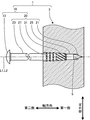
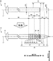
遊技盤3は、例えば、木製とされる。但し、遊技盤3は、樹脂製としてもよい。遊技盤3には、障害釘10が固定される位置に、穴部5が形成される。障害釘10は、穴部5に挿入された状態で、遊技盤3に固定される。弾球遊技機1では、遊技盤3に固定された障害釘10に、遊技球が衝突する。障害釘10に衝突した遊技球は、所定の方向に反発する。
The
弾球遊技機1では、軸心L1,L2を一致させた状態で、障害釘10を、穴部5に挿入し、遊技盤3に固定することが可能となる。軸心L1は、障害釘10の軸心(中心軸)を示す。軸心L2は、穴部5の軸心(中心軸)を示す。実施形態では、障害釘10の軸心L1に沿った方向を「軸方向」という。図1及び後述する図4に示すように、軸心L1,L2が一致した状態では、軸心L2は、軸方向に沿う。軸方向の一方側(障害釘10の先端側)を「第一側」といい、軸方向の他方側(障害釘10の後端側)を「第二側」という。軸方向に直交する方向を「径方向」という。
In the ball game machine 1, the
<障害釘>
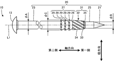
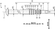
障害釘10について、図2及び図3を参照して説明する。実施形態における障害釘10では、軸方向の全領域において、軸心L1に垂直な断面形状は、軸心L1を中心とする円形又は円に近い外形とされている。前述した断面形状が円に近い外形となる部分(後述する「ローレット部32」及び「隆起部29」の外周参照)においても、径方向の先端は、所定の直径の円周上に配置することとしている。従って、実施形態では、障害釘10の各部における径方向の寸法を表す用語として「外径」を用いる。
<Disability nails>
The
障害釘10は、公知の障害釘と同様、金属材料により形成される。障害釘10を形成する金属材料としては、例えば、黄銅が挙げられる。障害釘10は、図2に示すように、頭部13と軸部20を備える。頭部13と軸部20は、一体をなす。頭部13は、軸方向の第二側における障害釘10の端部に設けられる。頭部13は、公知の障害釘と同様である。従って、頭部13に関する説明は省略する。
The
軸部20は、図2に示すように、先端部21と、弾球衝突部23と、ガイド部25と、突出部27と、拡大部31を備える。軸部20において、前述した各部は、軸方向の第一側から第二側に、先端部21、ガイド部25、拡大部31、突出部27及び弾球衝突部23の順で配置される。即ち、先端部21は、軸方向の第一側における障害釘10の端部に設けられる。弾球衝突部23は、先端部21と頭部13の間に設けられる。ガイド部25は、先端部21と弾球衝突部23の間に設けられる。突出部27は、ガイド部25と弾球衝突部23の間に設けられる。拡大部31は、ガイド部25と突出部27の間に設けられる。
As shown in FIG. 2, the
先端部21は、障害釘10の先端を形成する。先端部21は、軸方向の第二側から第一側に向けて先細りした形状を有する。先端部21の形状は、円錐とされる。但し、先端部21の形状は、円錐台としてもよい。先端部21の形状は、諸条件を考慮して適宜決定される。
The
弾球衝突部23は、外径が第一値である円柱形状を有する。実施形態では、第一値である外径を「外径φA」という。弾球衝突部23は、軸方向の第二側で、頭部13の軸方向の第一側に隣接し、頭部13と一体をなす。弾球遊技機1において、遊技球は、弾球衝突部23に衝突する。
The
ガイド部25は、外径が第二値である円柱形状を有する。実施形態では、第二値である外径を「外径φB」という。外径φA,φBの関係は、「外径φA>外径φB」である(図2参照)。ガイド部25は、軸方向の第一側で、軸方向の第二側における先端部21の端部に隣接する。ガイド部25の外径φBは、軸方向の第二側における先端部21の端部の外径に一致する。
The
突出部27は、図2に示すように、環状の溝部28と、環状の隆起部29によって形成される。実施形態では、溝部28と隆起部29は、共に軸心L1を中心とした円環状とされている。溝部28と隆起部29は、軸方向に隣接した状態で設けられる。実施形態における突出部27では、1組の溝部28と隆起部29は、軸方向に3組連続して設けられている。即ち、突出部27では、溝部28と隆起部29は、軸方向の第一側から第二側に向けて、溝部28、隆起部29、溝部28、隆起部29、溝部28及び隆起部29の順で繰り返して形成されている。突出部27において、溝部28と隆起部29が繰り返される回数は、3回とは異なる数としてもよい。
As shown in FIG. 2, the protruding
溝部28は、円周方向に連なる無端溝である。溝部28は、円環状の面と、傾斜した面によって形成される(図2参照)。溝部28を形成する円環状の面は、径方向に沿って配置される。溝部28を形成する傾斜した面は、軸心L1(軸方向)と、軸心L1に直交する仮想直線(径方向)に対して傾斜する。傾斜方向は、軸方向の第二側から第一側に向けて、径方向を軸心L1の側に接近する方向である。溝部28の溝形状は、前述した形状とは異なる形状としてもよい。溝部28の溝形状は、諸条件を考慮して適宜決定される。
The
隆起部29は、径方向に隆起した円周方向に連なる突起である。隆起部29の外径φCは、外径φAより大きくされる。軸部20において、外径φCである隆起部29は、最も太い部分となる。隆起部29の頂部の形状は、円筒状の面とされている。但し、隆起部29の頂部の形状は、これとは異なる形状としてもよい。隆起部29の頂部の形状は、諸条件を考慮して適宜決定される。実施形態では、隆起部29の外周には、後述する凹部33及び凸部34に対応する凹凸によるローレット目が形成されている(図2及び図5下段参照)。この点については後述する。
The raised
突出部27は、軸方向の第二側で、軸方向の第一側における弾球衝突部23の端部と隣接する。但し、突出部27と弾球衝突部23の間に、径方向の寸法(外径)が、外径φA以上で、外径φCより小さい所定の構成、又は外径φA未満の所定の構成を設けるようにしてもよい。前述した所定の構成としては、例えば、上述した特許文献4に記載された中間部が挙げられる。
The protruding
拡大部31は、図2に示すように、ローレット部32と、境界部35を備える。ローレット部32の外周には、ローレット目が全周に亘って形成される。ローレット目は、凹部33と凸部34を含む。実施形態では、ローレット目を形成する凹部33と凸部34は、共に螺旋状とされている。即ち、ローレット部32の外周には、螺旋状の凹部33と螺旋状の凸部34によるローレット目が、全周に亘って形成されている。ローレット部32は、軸方向の第二側で、軸方向の第一側における突出部27の端部と隣接する。境界部35は、軸方向の第一側で、軸方向の第二側におけるガイド部25の端部と隣接し、且つ軸方向の第二側で、軸方向の第一側におけるローレット部32の端部と隣接する。境界部35では、所定の領域(後述する図5下段に示す「領域R7」参照)に、ローレット部32の外周に形成されたローレット目の端部が形成される。
As shown in FIG. 2, the
ローレット部32は、軸心L1(軸方向)に対する傾斜角が角度θ1で、軸方向の第二側から第一側に向けて先細りした形状を有する(図3参照)。境界部35は、軸心L1(軸方向)に対する傾斜角が角度θ2で、軸方向の第二側から第一側に向けて先細りした形状を有する(図3参照)。角度θ2は、角度θ1より大きな値とされる。即ち、拡大部31は、全体として、軸方向の第二側から第一側に向けて先細りした形状を有する。実施形態では、上述した通り、ローレット部32の外周及び境界部35の外周の一部に、ローレット目が形成されているものの、ローレット部32及び境界部35の各形状は、共に円錐台状とされている。
The
ローレット部32の外径は、軸方向の全領域において、外径φA以上とされる。即ち、ローレット部32は、外径φAより大きくなる部分を含む。但し、ローレット部32の外径は、軸方向の所定の位置より軸方向の第一側において、外径φAより小さくなり、前述した所定の位置から軸方向の第二側において、外径φA以上となるようにしてもよい。図3に示す外径φDは、ローレット部32の外周を全周に亘って形成される複数の凸部34の先端円の直径である。外径が先端円の直径であることは、外周に凹部33及び凸部34に対応するローレット目が形成される隆起部29の外径φCについても同じである。境界部35では、先細り端部の外径は、外径φBに一致する。ローレット部32と境界部35の隣接面における両部の外径は、同一とされる。
The outer diameter of the
<取付方法>
取付方法について、図1及び図4を参照して説明する。障害釘10は、取付方法によって、遊技盤3に取り付けられ、遊技盤3に固定される(図1参照)。取付方法の実施に際し、遊技盤3には穴部5が事前に形成される。穴部5は、内径φEがガイド部25の外径φBに対応した値の穴である。穴部5の内径φEは、ガイド部25の外径φB(図2参照)より僅かに大きな値又は僅かに小さな値とされる。穴部5の内径φEは、外径φBと同一としてもよい。穴部5の内径φEは、諸条件を考慮して適宜設定される。例えば、ガイド部25の穴部5へのスムーズな挿入と、ガイド部25を介した穴部5による障害釘10のガイドを考慮し、穴部5の内径φEは、外径φBに対して、−0.2mm〜0.2mm程度の値とされる。
<Mounting method>
An attachment method will be described with reference to FIGS. 1 and 4. The
取付方法では、先端部21が穴部5に仮挿入された状態で、頭部13に力が付与される。例えば、頭部13に付与される力は、所定の工具又は装置によって発生される衝撃力である。障害釘10は、頭部13に付与された力によって、穴部5を底の側へと移動する。即ち、頭部13に付与された力は、障害釘10を穴部5に挿入する挿入荷重となる。先端部21の全体が穴部5に挿入されると、その後、ガイド部25が穴部5に挿入される。これに伴い、障害釘10は、ガイド部25の外周が穴部5の内周に倣った状態で支持される。つまり、障害釘10は、遊技盤3に対して、軸心L1が軸心L2に一致した状態となる。障害釘10は、このような状態のまま、更に、穴部5を底の側へと移動する。
In the attachment method, a force is applied to the
続けて、障害釘10は、拡大部31で穴部5を漸次変形させながら、穴部5を底の側へと移動する。このとき、穴部5の内周は、凸部34によって変形し、変形した部分が、凹部33へと流入する。これに伴い、凹部33には、変形した部分が充填される。その後、突出部27が穴部5に挿入されると、穴部5の内周は、更に隆起部29によって変形し、変形した部分が、溝部28へと流入する。これに伴い、溝部28には、変形した部分が充填される。このようにして、障害釘10は、図1に示す状態となる。これに伴い、1本の障害釘10を対象とした取付方法が終了する。図1に示す状態において、障害釘10は、ガイド部25が穴部5に嵌め合わされた状態となっている。
Subsequently, the
図1に示す例では、先端部21が穴部5の底にくい込んでいる。障害釘10を遊技盤3に対して、前述したような状態とすることで、遊技盤3から障害釘10を抜き取る際の荷重を高めることが可能となり、障害釘10の引抜強度を向上させることができる。換言すれば、このような状態によって、障害釘10の遊技盤3からの脱落を、突出部27及び拡大部31と共に抑制することが可能となる。
In the example shown in FIG. 1, the
<障害釘の製造方法>
障害釘10の製造方法について、図5を参照して説明する。障害釘10は、図5上段に示すような、素材釘40を加工して形成される。素材釘40の軸心L1は、そのまま、障害釘10の軸心L1となる。従って、実施形態において、障害釘10の軸心L1に沿った方向として定義される「軸方向」は、素材釘40の軸心L1に沿った方向でもある。素材釘40は、例えば、所定の長さの円柱形状の素材を鍛造する等して形成される。素材釘40は、頭部13と、軸基材41を備える。頭部13と軸基材41は一体をなす。頭部13は、例えば鍛造によって素材釘40を形成する際に形成される。頭部13は、そのまま、障害釘10の頭部13となる。換言すれば、障害釘10の頭部13は、素材釘40を形成する際に形成される。頭部13は、素材釘40の軸方向の第二側に形成される。
<Manufacturing method of obstacle nails>
A method for manufacturing the
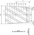
軸基材41は、第一素材部42と、第二素材部43と、第三素材部44を備える。第一素材部42は、円柱形状を有する。第一素材部42の外径は、外径φAとされる。第二素材部43は、円柱形状を有する。第二素材部43の外径は、外径φBとされる。第三素材部44は、軸方向の第二側から第一側に向けて外径φAから外径φBへと先細りした形状を有する。第三素材部44は、軸方向の第一側で、軸方向の第二側における第二素材部43の端部と隣接する。第三素材部44は、軸方向の第二側で、軸方向の第一側における第一素材部42の端部と隣接する。
The
素材釘40を対象とした障害釘10の製造方法は、軸基材41から軸部20を形成する成形工程を含む。この成形工程では、軸基材41に対して転造が施される。
The method for manufacturing the
軸基材41に対する転造には、一対の成形金型が用いられる。実施形態では、一対の成形金型の図示は省略されている。各成形金型の成形面は、第一成形部と、第二成形部と、第三成形部を含む。第一成形部は、先端部21を成形する部分である。第二成形部は、拡大部31と、隆起部29の外周におけるローレット目を成形する部分である。隆起部29の外周におけるローレット目は、省略することもできる。この場合、第二成形部は、拡大部31を成形する部分となる。第三成形部は、突出部27を成形する部分である。一対の成形金型は、第一成形部と第二成形部と第三成形部を含む成形面が所定の隙間を隔てて対向する状態で、転造装置に取り付けられる。素材釘40は、転造装置にセットされる。転造装置では、一対の成形金型における第一金型と第二金型の各成形面が、素材釘40の周方向に対応する方向に相対移動される。素材釘40は、軸基材41が、成形面が対向配置された一対の成形金型(第一金型及び第二金型)の間に挟み込まれた状態で、周方向に回転する。
A pair of molding dies is used for rolling the
回転する素材釘40では、第二素材部43の領域R1が、一対の成形金型の各第一成形部によって塑性変形される。領域R1は、軸方向の第一側における第二素材部43の端部を含む、第二素材部43の一部の領域である。これに伴い、第二素材部43の領域R1が、円錐状とされる。このとき、第二素材部43の領域R1では、素材が軸方向の第一側へと流れ、領域R1は、軸方向の第一側に伸張する。このようにして、第二素材部43の領域R1は、先端部21となる。第二素材部43の領域R2は、そのまま、外径φBのガイド部25となる。領域R2は、領域R1を除く第二素材部43の領域である。領域R2は、一対の成形金型の成形面によっては加工(転造)されない。
In the
回転する素材釘40では、第一素材部42の領域R3が、一対の成形金型の各第二成形部によって塑性変形される。領域R3は、軸方向の第一側における第一素材部42の端部を含む、第一素材部42の一部の領域である。実施形態では、領域R3のうち、軸方向の第一側の端部を含む領域を「領域R4」といい、領域R4に対して軸方向の第二側となる領域を「領域R5」という。これに伴い、第一素材部42の領域R3には、螺旋状の凹部と凸部によるローレット目が外周に形成される。このとき、少なくとも領域R3の一部である領域R4は、軸心L1(軸方向)に対する傾斜角が角度θ1で、軸方向の第二側から第一側に向けて先細りした形状へと塑性変形される。領域R3の全体が、前述したように先細りした形状へと塑性変形されるようにしてもよい。先細り端部の外径は、例えば、外径φAのままとされる。前述した先細り端部の外径は、形成されたローレット目における凸部の先端に対応した先端円の外径である。
In the
領域R4を上述したように塑性変形させた場合、軸方向の第一側における領域R4の端部では、この部分を形成する素材が、軸方向の第一側に設けられた第三素材部44の側へと流れる。これに伴い、軸方向の第二側における第三素材部44の領域R7には、領域R4に形成された凸部の端部が形成される(図5下段参照)。領域R7は、軸方向の第二側における第三素材部44の端部を含む、第三素材部44の一部の領域である。
When the region R4 is plastically deformed as described above, the material forming this portion is the
このようにして、領域R4は、ローレット部32となり、第三素材部44は、境界部35となる。このとき、領域R4の外周に形成されたローレット目は、ローレット部32の外周におけるローレット目となる。つまり、領域R4の外周における螺旋状の凹部は、螺旋状の凹部33となり、領域R4の外周における螺旋状の凸部は、螺旋状の凸部34となる。即ち、領域R4と第三素材部44は、拡大部31となる。上記では説明を省略したが、第三素材部44では、外周を、外径φAから外径φBへとする傾斜角は、転造後の角度θ2に対応する角度とされる。一対の成形金型の第一成形部と第二成形部による転造は、例えば、同じタイミングで行うようにしてもよい。
Thus, the region R4 becomes the
領域R3の外周にローレット目が形成された後、一対の成形金型における第一金型と第二金型の各成形面の相対移動は、更に継続される。この相対移動に応じて回転する素材釘40では、第一素材部42の領域R5が、一対の成形金型の各第三成形部によって塑性変形される。これに伴い、第一素材部42の領域R5には、径方向に凹んだ円環状の溝部と径方向に隆起した円環状の隆起部が、軸方向に交互に繰り返して各3個形成される。円環状の隆起部の外周には、第二成形部によって領域R5の外周に形成された螺旋状の凹部と螺旋状の凸部によるローレット目が残存することとなる。このようにして、領域R5は、突出部27となる。このとき、領域R5に形成された円環状の溝部は、円環状の溝部28となり、領域R5に形成された円環状の隆起部は、円環状の隆起部29となる。
After the knurls are formed on the outer periphery of the region R3, the relative movement of the molding surfaces of the first mold and the second mold in the pair of molding dies is further continued. In the
第一素材部42の領域R6は、そのまま、外径φAの弾球衝突部23となる。領域R6は、領域R3(領域R4及び領域R5)を除く第一素材部42の領域である。領域R6は、一対の成形金型の成形面によっては加工(転造)されない。
The region R6 of the
<実施形態の効果>
実施形態によれば、次のような効果を得ることができる。
<Effect of embodiment>
According to the embodiment, the following effects can be obtained.
(1)障害釘10の軸部20は、先端部21と、弾球衝突部23と、ガイド部25と、突出部27と、拡大部31を備える(図2参照)。突出部27は、円環状の溝部28と円環状の隆起部29によって形成される(図2参照)。溝部28と隆起部29は、軸方向に隣接した状態で設けられる。隆起部29の外径は、軸部20において最も太くなる外径φCとされる(図2参照)。境界部35と共に拡大部31を形成するローレット部32の外周には、螺旋状の凹部33と螺旋状の凸部34によるローレット目が、全周に亘って形成される(図3参照)。そのため、突出部27と拡大部31によって、障害釘10を遊技盤3に固定することができる。例えば、弾球の衝突による障害釘10の抜け落ちと回転を抑制することができる。
(1) The
(2)ローレット部32は、軸心L1(軸方向)に対する傾斜角が角度θ1で、軸方向の第二側から第一側に向けて先細りした形状とされる(図3参照)。境界部35は、軸心L1(軸方向)に対する傾斜角が角度θ2(角度θ2>角度θ1)で、軸方向の第二側から第一側に向けて先細りした形状とされる(図3参照)。
(2) The
そのため、軸基材41を転造し軸部20を形成する際、軸方向の第一側において、螺旋状の凸部34の端部を、境界部35の側へと、緩やかに傾斜させ、逃がすことができる。即ち、軸方向の第一側において、凸部34の端部を、境界部35の側へと、緩やかに傾斜させ、逃がした形状とすることができる。障害釘10では、ローレット目の形成に伴う外径の急激な変化(拡大)を、境界部35によって抑制することができる。つまり、ローレット目を形成したとしても、穴部5への挿入を阻害する可能性のある段差の発生を、境界部35によって抑制することができる。拡大部31を穴部5に挿入する際、挿入荷重の急激な増加を抑制しつつ、内径φEの穴部5を径方向に拡大させ、その後、突出部27の挿入へと移行することができる。障害釘10の遊技盤3へのスムーズな取り付けを実現することができる。穴部5の内径φEを、前述の段差を考慮した値とする必要がなく、ガイド部25の外径φBに対応した値に設定することができる。障害釘10の取り付け途中における、障害釘10の軸心L1と穴部5の軸心L2の一致度を向上させることができる。遊技盤3の材質に関わらず、障害釘10を遊技盤3に精度よく配列し固定することができる。
Therefore, when rolling the
(3)ガイド部25は、軸方向の第二側で、軸方向の第一側における先端部21の端部と隣接した状態で設けられる(図2参照)。そのため、先端部21が穴部5に挿入された直後に、ガイド部25を、穴部5に挿入することができる(図4参照)。先端部21の穴部5への挿入からガイド部25の穴部5への挿入へと、スムーズに移行することができる。先端部21が挿入された後、取り付け途中の障害釘10がぐらつくことを抑制することができる。
(3) The
<変形例>
実施形態は、次のようにすることもできる。以下に示す変形例のうちの幾つかの構成は、適宜組み合わせて採用することもできる。以下では上記とは異なる点を説明することとし、同様の点についての説明は適宜省略する。
<Modification>
The embodiment can also be performed as follows. Some configurations of the modifications shown below can be appropriately combined and employed. Hereinafter, points different from the above will be described, and description of similar points will be omitted as appropriate.
(1)上記では、ローレット部32の外周に形成されたローレット目が、螺旋状の凹部33と、螺旋状の凸部34である構成を例に説明した(図1〜図5参照)。ローレット部の外周には、上記とは異なるローレット目を形成するようにしてもよい。例えば、ローレット部の外周に形成されるローレット目は、平目又はアヤ目としてもよい。ローレット部の外周に形成されるローレット目は、諸条件を考慮して適宜決定される。
(1) In the above description, the configuration in which the knurled eyes formed on the outer periphery of the
遊技盤3に固定された状態において、障害釘10の回転強度を確保することができており、障害釘10の回転が大きな問題とならない場合、ローレット部32の外周におけるローレット目は、省略するようにしてもよい。この場合、拡大部は、軸心(軸方向)に対する傾斜角が所定の一定の角度で、軸方向の第二側から第一側に向けて先細りした、単一の円錐台部(テーパ部)とされる。拡大部の先細り端部の外径は、ガイド部25の外径に一致する外径φBとされる。突出部27を形成する隆起部29の外周におけるローレット目も、省略される。但し、突出部には、隆起部の外周に、所定のローレット目を形成するようにしてもよい。
When the
(2)上記では、障害釘10の軸部20に、突出部27と拡大部31を設けた構成を例に説明した(図1、図2、図4及び図5参照)。遊技盤3に固定された状態において、障害釘10の引抜強度を確保することができており、障害釘10の抜け落ちが大きな問題とならない場合、突出部27は、省略するようにしてもよい。上述した通り、穴部5を底のある穴とし(図1及び図4参照)、先端部21を穴部5の底にくい込ませると、引抜強度を向上させることが可能となる。
(2) In the above description, the configuration in which the protruding
(3)上記では、拡大部31を備える障害釘10を例に説明した(図2参照)。拡大部31において、ローレット部32は、軸心L1(軸方向)に対する傾斜角が角度θ1で、軸方向の第二側から第一側に向けて先細りした形状を有する(図2参照)。障害釘10において、拡大部31のローレット部32の形状は、図6に示すような形状としてもよい。図6では、図1〜図5との対応を考慮し、各部に対する符号は、上記と同じとしている。即ち、図6に示す障害釘10では、ローレット部32は、外周が傾斜面とはされておらず、円柱形状とされている。ローレット部32の外径(凸部34の先端に対応した先端円の外径)は、諸条件を考慮して適宜決定される。例えば、ローレット部32の外径は、外径φA,φBより大きく、外径φCより小さな値とされる。
(3) In the above description, the
(4)上記では、遊技盤3に形成された穴部5を、底を有する穴とした。穴部は、遊技盤を、遊技盤の板厚方向に貫通した穴としてもよい。
(4) In the above description, the hole 5 formed in the
1 弾球遊技機、 3 遊技盤、 5 穴部、 10 障害釘、 13 頭部
20 軸部、 21 先端部、 23 弾球衝突部、 25 ガイド部
27 突出部、 28 溝部、 29 隆起部、 31 拡大部
32 ローレット部、 33 凹部、 34 凸部、 35 境界部 40 素材釘
41 軸基材、 42 第一素材部、 43 第二素材部、 44 第三素材部
L1,L2 軸心、 R1,R2,R3,R4,R5,R6,R7 領域
θ1,θ2 角度、φA,φB,φC,φD 外径、 φE 内径
DESCRIPTION OF SYMBOLS 1 Ball game machine, 3 Game board, 5 Hole part, 10 Obstruction nail, 13
Claims (6)
前記頭部は、前記障害釘の軸心に沿った軸方向の第一側とは反対側となる前記軸方向の第二側における前記障害釘の端部に設けられ、
前記軸部は、
前記軸方向の第二側から第一側に向けて先細りした形状を有し、前記軸方向の第一側における前記障害釘の端部に設けられる先端部と、
前記軸方向に直交する径方向の寸法が第一値である円柱形状を有し、前記先端部と前記頭部との間に設けられる弾球衝突部と、
前記径方向の寸法が、前記軸方向の第二側における前記先端部の端部の前記径方向の寸法に一致する第二値である円柱形状を有し、前記先端部と前記弾球衝突部との間に設けられるガイド部と、
環状の溝部と、前記径方向の寸法が前記第一値より大きい環状の隆起部と、によって形成され、前記ガイド部と前記弾球衝突部との間に設けられる突出部と、
前記軸方向の第二側から第一側に向けて先細りした形状を有し、先細り端部の前記径方向の寸法が前記第二値で、前記ガイド部と前記突出部との間に設けられる第一拡大部と、を備える、障害釘。 An obstruction nail of a ball game machine comprising a head and a shaft that is integral with the head,
The head is provided at an end of the obstacle nail on the second side in the axial direction opposite to the first axial side along the axis of the obstacle nail;
The shaft portion is
A tip portion tapered from the second side in the axial direction toward the first side, and provided at an end portion of the obstacle nail on the first side in the axial direction;
A cylindrical shape having a first dimension in a radial direction perpendicular to the axial direction, and a bullet ball collision portion provided between the tip and the head;
The radial dimension has a cylindrical shape that is a second value that matches the radial dimension of the end of the tip on the second side in the axial direction, and the tip and the ball impacting part A guide portion provided between and
A projecting portion formed between the guide portion and the bullet ball collision portion, formed by an annular groove portion and an annular ridge portion having a radial dimension larger than the first value;
It has a shape tapered from the second side in the axial direction toward the first side, and the radial dimension of the tapered end portion is the second value, and is provided between the guide portion and the protruding portion. A obstacle nail comprising a first enlarged portion.
前記第一拡大部は、
前記障害釘の軸心に対する傾斜角が第一角度で、前記軸方向の第二側から第一側に向けて先細りした形状を有し、ローレット目が外周に形成され、前記径方向の寸法が前記第一値より大きい第一ローレット部と、
前記障害釘の軸心に対する傾斜角が前記第一角度より大きい第二角度で、前記軸方向の第二側から第一側に向けて先細りした形状を有し、先細り端部の前記径方向の寸法が前記第二値で、前記軸方向の第一側で、前記軸方向の第二側における前記ガイド部の端部と隣接し、且つ前記軸方向の第二側で、前記軸方向の第一側における前記第一ローレット部の端部と隣接する第一境界部と、を備える、請求項1に記載の障害釘。 The guide portion has a cylindrical shape that is the second value smaller than the first value in the radial dimension,
The first enlarged portion is
The obstacle nail has a first angle of inclination with respect to the axis, and has a shape that tapers from the second side in the axial direction toward the first side, knurled eyes are formed on the outer periphery, and the radial dimension is A first knurled portion greater than the first value;
The obstruction nail has a second angle greater than the first angle and a taper shape from the second side in the axial direction toward the first side, and the radial direction of the tapered end portion The dimension is the second value, on the first side in the axial direction, adjacent to the end of the guide portion on the second side in the axial direction, and on the second side in the axial direction. The obstacle nail according to claim 1, further comprising: a first boundary portion adjacent to an end portion of the first knurl portion on one side.
前記頭部は、前記障害釘の軸心に沿った軸方向の第一側とは反対側となる前記軸方向の第二側における前記障害釘の端部に設けられ、
前記軸部は、
前記軸方向の第二側から第一側に向けて先細りした形状を有し、前記軸方向の第一側における前記障害釘の端部に設けられる先端部と、
前記軸方向に直交する径方向の寸法が第一値である円柱形状を有し、前記先端部と前記頭部との間に設けられる弾球衝突部と、
前記径方向の寸法が、前記軸方向の第二側における前記先端部の端部の前記径方向の寸法に一致する、前記第一値より小さい第二値である円柱形状を有し、前記先端部と前記弾球衝突部との間に設けられるガイド部と、
ローレット目が外周に形成され、前記径方向の寸法が前記第一値より大きい第二ローレット部と、前記軸方向の第二側から第一側に向けて先細りした形状を有し、先細り端部の前記径方向の寸法が前記第二値で、前記軸方向の第一側で、前記軸方向の第二側における前記ガイド部の端部と隣接し、且つ前記軸方向の第二側で、前記軸方向の第一側における前記第二ローレット部の端部と隣接する第二境界部と、を備え、前記ガイド部と前記弾球衝突部との間に設けられる第二拡大部と、を備える、障害釘。 An obstruction nail of a ball game machine comprising a head and a shaft that is integral with the head,
The head is provided at an end of the obstacle nail on the second side in the axial direction opposite to the first axial side along the axis of the obstacle nail;
The shaft portion is
A tip portion tapered from the second side in the axial direction toward the first side, and provided at an end portion of the obstacle nail on the first side in the axial direction;
A cylindrical shape having a first dimension in a radial direction perpendicular to the axial direction, and a bullet ball collision portion provided between the tip and the head;
The distal end has a cylindrical shape having a second value smaller than the first value, the radial dimension being equal to the radial dimension of the end of the distal end on the second side in the axial direction, A guide part provided between the part and the bullet impact part;
A knurled eye is formed on the outer periphery, the second knurled portion having a radial dimension larger than the first value, and a shape tapered from the second side in the axial direction toward the first side, and a tapered end portion The radial dimension of the second value, on the first side in the axial direction, adjacent to the end of the guide portion on the second side in the axial direction, and on the second side in the axial direction, A second boundary portion adjacent to an end portion of the second knurl portion on the first side in the axial direction, and a second enlarged portion provided between the guide portion and the bullet impact portion, Prepare the obstacle nail.
穴部が形成され、前記障害釘が前記穴部に固定された遊技盤と、を備え、
前記障害釘は、前記ガイド部が前記穴部に嵌め合わされた状態で、前記穴部に固定されている、弾球遊技機。 The obstacle nail according to any one of claims 1 to 4,
A game board in which a hole is formed and the obstacle nail is fixed to the hole,
The obstacle nail is a ball game machine in which the guide portion is fixed to the hole portion in a state where the guide portion is fitted in the hole portion.
前記頭部が設けられる前記障害釘の軸心に沿った軸方向の第二側から、前記軸方向の第二側とは反対側となる前記軸方向の第一側に向けて先細りした形状を有し、前記軸方向の第一側における前記障害釘の端部に設けられる先端部と、前記軸方向に直交する径方向の寸法が第一値である円柱形状を有し、前記先端部と前記頭部との間に設けられる弾球衝突部と、前記径方向の寸法が、前記軸方向の第二側における前記先端部の端部の前記径方向の寸法に一致する、前記第一値より小さい第二値である円柱形状を有し、前記先端部と前記弾球衝突部との間に設けられるガイド部と、ローレット目が外周に形成され、前記径方向の寸法が前記第一値より大きいローレット部と、前記軸方向の第二側から第一側に向けて先細りした形状を有し、先細り端部の前記径方向の寸法が前記第二値で、前記軸方向の第一側で、前記軸方向の第二側における前記ガイド部の端部と隣接し、且つ前記軸方向の第二側で、前記軸方向の第一側における前記ローレット部の端部と隣接する境界部と、を備え、前記ガイド部と前記弾球衝突部との間に設けられる拡大部と、を備える前記軸部を、軸基材を加工して形成する成形工程を含み、
前記成形工程は、
前記径方向の寸法が前記第一値である円柱形状の第一素材部と、前記径方向の寸法が前記第二値である円柱形状の第二素材部と、前記軸方向の第二側から第一側に向けて前記第一値から前記第二値へと先細りした形状を有し、前記軸方向の第一側で、前記軸方向の第二側における前記第二素材部の端部と隣接し、且つ前記軸方向の第二側で、前記軸方向の第一側における前記第一素材部の端部と隣接する第三素材部と、を備える前記軸基材のうち、前記軸方向の第一側における前記第二素材部の端部を含む、前記第二素材部の一部の領域を塑性変形させて前記先端部を形成する工程と、
前記軸基材のうち、前記軸方向の第一側における前記第一素材部の端部を含む、前記第一素材部の一部の領域を塑性変形させて前記ローレット部を形成する工程と、を含む製造方法。 A method of manufacturing an obstacle nail for a ball game machine, comprising: a head; and a shaft portion integrated with the head.
A shape tapered from a second side in the axial direction along the axis of the obstacle nail provided with the head toward the first side in the axial direction which is opposite to the second side in the axial direction. A tip portion provided at an end portion of the obstacle nail on the first side in the axial direction, and a cylindrical shape having a first dimension in a radial direction orthogonal to the axial direction, and the tip portion The first value, wherein the ball-ball collision portion provided between the head and the radial dimension coincides with the radial dimension of the end of the tip on the second side in the axial direction. A cylindrical shape which is a smaller second value, a guide portion provided between the tip portion and the bullet impact portion, a knurled eye is formed on the outer periphery, and the radial dimension is the first value. It has a larger knurled portion and a shape that tapers from the second side in the axial direction toward the first side. The radial dimension of the end portion is the second value, on the first side in the axial direction, adjacent to the end portion of the guide portion on the second side in the axial direction, and on the second side in the axial direction And the boundary portion adjacent to the end portion of the knurled portion on the first side in the axial direction, and an enlarged portion provided between the guide portion and the bullet impact portion. Including a molding step of forming a shaft base material,
The molding step includes
From the cylindrical first material part whose radial dimension is the first value, the cylindrical second material part whose radial dimension is the second value, and from the second side in the axial direction. It has a shape tapered from the first value to the second value toward the first side, and on the first side in the axial direction, the end of the second material portion on the second side in the axial direction; The axial direction of the axial base material, comprising the third material portion adjacent to the end of the first material portion on the first side in the axial direction on the second side in the axial direction. A step of plastically deforming a partial region of the second material portion including an end portion of the second material portion on the first side of the first side, and
Of the shaft base material, including the end of the first material portion on the first side in the axial direction, plastically deforming a partial region of the first material portion to form the knurled portion; Manufacturing method.
Priority Applications (1)
| Application Number | Priority Date | Filing Date | Title |
|---|---|---|---|
| JP2015001882A JP6433299B2 (en) | 2015-01-07 | 2015-01-07 | Obstacle nail, ball game machine, and method of manufacturing obstruction nail |
Applications Claiming Priority (1)
| Application Number | Priority Date | Filing Date | Title |
|---|---|---|---|
| JP2015001882A JP6433299B2 (en) | 2015-01-07 | 2015-01-07 | Obstacle nail, ball game machine, and method of manufacturing obstruction nail |
Publications (2)
| Publication Number | Publication Date |
|---|---|
| JP2016123789A true JP2016123789A (en) | 2016-07-11 |
| JP6433299B2 JP6433299B2 (en) | 2018-12-05 |
Family
ID=56358450
Family Applications (1)
| Application Number | Title | Priority Date | Filing Date |
|---|---|---|---|
| JP2015001882A Active JP6433299B2 (en) | 2015-01-07 | 2015-01-07 | Obstacle nail, ball game machine, and method of manufacturing obstruction nail |
Country Status (1)
| Country | Link |
|---|---|
| JP (1) | JP6433299B2 (en) |
Cited By (2)
| Publication number | Priority date | Publication date | Assignee | Title |
|---|---|---|---|---|
| JP2017012256A (en) * | 2015-06-29 | 2017-01-19 | 株式会社三洋物産 | Game machine |
| JP2019076227A (en) * | 2017-10-20 | 2019-05-23 | サミー株式会社 | Game machine |
Citations (13)
| Publication number | Priority date | Publication date | Assignee | Title |
|---|---|---|---|---|
| JPS63165037A (en) * | 1986-12-25 | 1988-07-08 | Shinjiyou Seisakusho:Kk | Manufacture of driving pin in spread anchor |
| WO1992020851A1 (en) * | 1991-05-10 | 1992-11-26 | Organ Needle Co., Ltd. | Sewing machine needle and method of manufacturing same |
| JPH07275447A (en) * | 1994-04-13 | 1995-10-24 | Toei Seibiyou Kk | Manufacture of japanese pin ball game panel and nails for japanese pin ball game machine |
| JPH11216289A (en) * | 1998-02-04 | 1999-08-10 | Organ Needle Co Ltd | Sewing needle and manufacturing method thereof |
| JP2002291884A (en) * | 2001-01-25 | 2002-10-08 | Terumo Corp | Liquid injection needle and liquid injecting unit |
| JP2005021672A (en) * | 2003-06-10 | 2005-01-27 | Mitsubishi Pencil Co Ltd | Injection needle, injection needle manufacturing method, and injection needle manufacturing apparatus |
| JP3116027U (en) * | 2005-08-23 | 2005-11-24 | 東永製鋲株式会社 | Pachinko panels and nails used in the panels |
| JP2006102393A (en) * | 2004-10-08 | 2006-04-20 | Fukui Byora Co Ltd | Nail for bullet ball machine |
| JP2007105312A (en) * | 2005-10-14 | 2007-04-26 | Okumura Yu-Ki Co Ltd | Pachinko game machine |
| JP2009195971A (en) * | 2008-02-25 | 2009-09-03 | Asmo Co Ltd | Method for manufacturing shaft with step part, method for manufacturing armature shaft, and apparatus for forming shaft with step part |
| JP2010003870A (en) * | 2008-06-20 | 2010-01-07 | Denso Corp | Semiconductor device and manufacturing method thereof |
| JP2010004958A (en) * | 2008-06-24 | 2010-01-14 | Fukui Byora Co Ltd | Nail for pinball game machine and panel for pinball game machine |
| JP2014023718A (en) * | 2012-07-26 | 2014-02-06 | Sanyo Product Co Ltd | Game machine |
-
2015
- 2015-01-07 JP JP2015001882A patent/JP6433299B2/en active Active
Patent Citations (13)
| Publication number | Priority date | Publication date | Assignee | Title |
|---|---|---|---|---|
| JPS63165037A (en) * | 1986-12-25 | 1988-07-08 | Shinjiyou Seisakusho:Kk | Manufacture of driving pin in spread anchor |
| WO1992020851A1 (en) * | 1991-05-10 | 1992-11-26 | Organ Needle Co., Ltd. | Sewing machine needle and method of manufacturing same |
| JPH07275447A (en) * | 1994-04-13 | 1995-10-24 | Toei Seibiyou Kk | Manufacture of japanese pin ball game panel and nails for japanese pin ball game machine |
| JPH11216289A (en) * | 1998-02-04 | 1999-08-10 | Organ Needle Co Ltd | Sewing needle and manufacturing method thereof |
| JP2002291884A (en) * | 2001-01-25 | 2002-10-08 | Terumo Corp | Liquid injection needle and liquid injecting unit |
| JP2005021672A (en) * | 2003-06-10 | 2005-01-27 | Mitsubishi Pencil Co Ltd | Injection needle, injection needle manufacturing method, and injection needle manufacturing apparatus |
| JP2006102393A (en) * | 2004-10-08 | 2006-04-20 | Fukui Byora Co Ltd | Nail for bullet ball machine |
| JP3116027U (en) * | 2005-08-23 | 2005-11-24 | 東永製鋲株式会社 | Pachinko panels and nails used in the panels |
| JP2007105312A (en) * | 2005-10-14 | 2007-04-26 | Okumura Yu-Ki Co Ltd | Pachinko game machine |
| JP2009195971A (en) * | 2008-02-25 | 2009-09-03 | Asmo Co Ltd | Method for manufacturing shaft with step part, method for manufacturing armature shaft, and apparatus for forming shaft with step part |
| JP2010003870A (en) * | 2008-06-20 | 2010-01-07 | Denso Corp | Semiconductor device and manufacturing method thereof |
| JP2010004958A (en) * | 2008-06-24 | 2010-01-14 | Fukui Byora Co Ltd | Nail for pinball game machine and panel for pinball game machine |
| JP2014023718A (en) * | 2012-07-26 | 2014-02-06 | Sanyo Product Co Ltd | Game machine |
Cited By (2)
| Publication number | Priority date | Publication date | Assignee | Title |
|---|---|---|---|---|
| JP2017012256A (en) * | 2015-06-29 | 2017-01-19 | 株式会社三洋物産 | Game machine |
| JP2019076227A (en) * | 2017-10-20 | 2019-05-23 | サミー株式会社 | Game machine |
Also Published As
| Publication number | Publication date |
|---|---|
| JP6433299B2 (en) | 2018-12-05 |
Similar Documents
| Publication | Publication Date | Title |
|---|---|---|
| JP4492521B2 (en) | Method for manufacturing rotor shaft | |
| JP5083396B2 (en) | Fastening screw manufacturing method | |
| JP5046130B2 (en) | Rolling bearing and manufacturing method thereof | |
| JP2008005994A (en) | Iron type golf club head | |
| JP6433299B2 (en) | Obstacle nail, ball game machine, and method of manufacturing obstruction nail | |
| JP4255231B2 (en) | Blind rivet | |
| JP6567292B2 (en) | Method for manufacturing metal plate having holes, method for manufacturing external gear with peripheral hole, and method for manufacturing metal plate | |
| JP5397396B2 (en) | Manufacturing method of rotor core of rotating electrical machine | |
| US10960457B2 (en) | Rivet bonding mold | |
| JP6949428B2 (en) | Manufacturing method of pulley shaft for belt type continuously variable transmission | |
| JP4609050B2 (en) | Tripod type constant velocity joint | |
| JP2016161043A (en) | Self-tapping screw and manufacturing method thereof | |
| JP5779913B2 (en) | Spline molded body molding method and inner diameter spline tooth molding apparatus | |
| JP6292944B2 (en) | Mold strengthening method and forging mold | |
| JP2017012256A (en) | Game machine | |
| JP5016068B2 (en) | Obstacle nail for a ball game machine, a ball ball machine, a method for manufacturing an obstacle nail for a ball game machine, and a mold for forming an obstacle nail for a ball game machine | |
| JP2016118228A (en) | Wave-form holder and rivet caulking method | |
| JP6565965B2 (en) | Riveting mold | |
| JP5018854B2 (en) | Rotor shaft | |
| JP2010004958A (en) | Nail for pinball game machine and panel for pinball game machine | |
| JP2006158477A (en) | Socket and golf club using the same | |
| JP2010047989A (en) | Screw point | |
| RU2612857C1 (en) | Tool for planetary thread rolling with axial oscillation of moulding surface | |
| JP6704649B2 (en) | spring pin | |
| JP2010004957A (en) | Nail for pinball game machine and panel for pinball game machine |
Legal Events
| Date | Code | Title | Description |
|---|---|---|---|
| A621 | Written request for application examination |
Free format text: JAPANESE INTERMEDIATE CODE: A621 Effective date: 20171010 |
|
| A977 | Report on retrieval |
Free format text: JAPANESE INTERMEDIATE CODE: A971007 Effective date: 20180706 |
|
| A131 | Notification of reasons for refusal |
Free format text: JAPANESE INTERMEDIATE CODE: A131 Effective date: 20180717 |
|
| A521 | Request for written amendment filed |
Free format text: JAPANESE INTERMEDIATE CODE: A523 Effective date: 20180913 |
|
| TRDD | Decision of grant or rejection written | ||
| A01 | Written decision to grant a patent or to grant a registration (utility model) |
Free format text: JAPANESE INTERMEDIATE CODE: A01 Effective date: 20181030 |
|
| A61 | First payment of annual fees (during grant procedure) |
Free format text: JAPANESE INTERMEDIATE CODE: A61 Effective date: 20181106 |
|
| R150 | Certificate of patent or registration of utility model |
Ref document number: 6433299 Country of ref document: JP Free format text: JAPANESE INTERMEDIATE CODE: R150 |
|
| R250 | Receipt of annual fees |
Free format text: JAPANESE INTERMEDIATE CODE: R250 |
|
| R250 | Receipt of annual fees |
Free format text: JAPANESE INTERMEDIATE CODE: R250 |
|
| R250 | Receipt of annual fees |
Free format text: JAPANESE INTERMEDIATE CODE: R250 |
|
| R250 | Receipt of annual fees |
Free format text: JAPANESE INTERMEDIATE CODE: R250 |
|
| R250 | Receipt of annual fees |
Free format text: JAPANESE INTERMEDIATE CODE: R250 |