JP2016123772A - sewing machine - Google Patents
sewing machine Download PDFInfo
- Publication number
- JP2016123772A JP2016123772A JP2015001263A JP2015001263A JP2016123772A JP 2016123772 A JP2016123772 A JP 2016123772A JP 2015001263 A JP2015001263 A JP 2015001263A JP 2015001263 A JP2015001263 A JP 2015001263A JP 2016123772 A JP2016123772 A JP 2016123772A
- Authority
- JP
- Japan
- Prior art keywords
- cam
- feed
- sewing machine
- feed dog
- cam surface
- Prior art date
- Legal status (The legal status is an assumption and is not a legal conclusion. Google has not performed a legal analysis and makes no representation as to the accuracy of the status listed.)
- Granted
Links
Images


Classifications
-
- D—TEXTILES; PAPER
- D05—SEWING; EMBROIDERING; TUFTING
- D05B—SEWING
- D05B27/00—Work-feeding means
- D05B27/02—Work-feeding means with feed dogs having horizontal and vertical movements
- D05B27/04—Work-feeding means with feed dogs having horizontal and vertical movements arranged above the workpieces
-
- D—TEXTILES; PAPER
- D05—SEWING; EMBROIDERING; TUFTING
- D05B—SEWING
- D05B29/00—Pressers; Presser feet
- D05B29/12—Presser-foot attachment
-
- D—TEXTILES; PAPER
- D05—SEWING; EMBROIDERING; TUFTING
- D05B—SEWING
- D05B27/00—Work-feeding means
- D05B27/02—Work-feeding means with feed dogs having horizontal and vertical movements
-
- D—TEXTILES; PAPER
- D05—SEWING; EMBROIDERING; TUFTING
- D05B—SEWING
- D05B29/00—Pressers; Presser feet
- D05B29/06—Presser feet
-
- D—TEXTILES; PAPER
- D05—SEWING; EMBROIDERING; TUFTING
- D05B—SEWING
- D05B27/00—Work-feeding means
- D05B27/02—Work-feeding means with feed dogs having horizontal and vertical movements
- D05B27/08—Work-feeding means with feed dogs having horizontal and vertical movements with differential feed motions
-
- D—TEXTILES; PAPER
- D05—SEWING; EMBROIDERING; TUFTING
- D05D—INDEXING SCHEME ASSOCIATED WITH SUBCLASSES D05B AND D05C, RELATING TO SEWING, EMBROIDERING AND TUFTING
- D05D2209/00—Use of special materials
- D05D2209/08—Use of special materials elastic, e.g. rubber spring
Landscapes
- Engineering & Computer Science (AREA)
- Textile Engineering (AREA)
- Sewing Machines And Sewing (AREA)
Abstract
Description
本発明は、複数種類の縫いに対応するミシンに関する。 The present invention relates to a sewing machine corresponding to a plurality of types of sewing.
例えば、家庭用ミシンの場合には、一台で直線縫いやジグザグ縫い等の多彩な縫いが要求されることから、針板に形成される針穴は針振りにも対応できるように横幅が広い長穴状に形成されており、これに伴い、送り歯や押さえ足も横幅が広いものが使用されている。
しかしながら、押さえ足の幅が広いと、布地の針落ち位置が押さえ足に隠される、針落ち位置の近くに手を置いて作業ができない等、作業性が低下するため、従来のミシンでは、縫いの種類に応じて押さえ足を交換としていた(例えば、特許文献1参照)。
For example, in the case of a household sewing machine, since a variety of sewing such as straight stitching and zigzag stitching is required with a single machine, the needle hole formed in the needle plate has a wide width so that it can also handle needle swinging It is formed in the shape of a long hole. Along with this, a feed dog and a presser foot having a wide width are used.
However, if the width of the presser foot is wide, the workability will be reduced, for example, the needle drop position of the fabric will be hidden behind the presser foot and the hand will not be placed near the needle drop position. The presser foot is exchanged according to the type of (see, for example, Patent Document 1).
しかしながら、上記従来のミシンは、押さえ足の交換は可能としているが、送り歯はミシンベッド部内に設けられ、交換が容易ではないことから、交換可能とはされていなかった。このため、ジグザグ縫いに対応する幅の広い送り歯のままで直線縫いも行わねばならず、作業性の向上を十分に図ることができなかった。また、広い範囲で送り歯が出没するので、送り歯によって布地が傷つくおそれがあるなど、縫い品質の低下も懸念されていた。 However, although the conventional sewing machine can replace the presser foot, the feed dog is provided in the sewing machine bed portion and is not easy to replace. For this reason, it is necessary to perform straight stitching with a wide feed dog corresponding to zigzag stitching, and workability cannot be improved sufficiently. Further, since the feed dog appears and disappears in a wide range, there is a concern that the sewing quality may be deteriorated, for example, the fabric may be damaged by the feed dog.
本発明は、容易に送り歯の交換が可能なミシンの送り機構を提供することをその目的とする。 SUMMARY OF THE INVENTION An object of the present invention is to provide a feed mechanism for a sewing machine that can easily replace a feed dog.
請求項1記載の発明は、
布押さえ及び針板を縫いの種類に応じて交換可能なミシンにおいて、
被縫製物の送り方向に沿った動作を付与される送り台と、前記針板の上の被縫製物を送る送り歯とを備え、
前記送り台に前記送り歯を分離可能に装着する装着部を備え、
前記送り歯は、前記装着部に装着するためのカム部を備え、
前記装着部は、前記カム部が挿入される対向状態の第一受け面及び第二受け面と、これらに挿入された前記カム部を挿入方向に押圧する押圧部材とを備え、
前記カム部は、
平坦な前記第一受け面に面接触する平坦な第一カム面と、
前記第二受け面の端部に対して、前記カム部が挿入される挿入方向に直交する方向に沿った線による線接触を行う第二カム面と、
前記押圧部材に押圧される第三カム面と、を備えたことを特徴とする。
The invention described in claim 1
In the sewing machine that can replace the cloth presser and throat plate according to the type of sewing,
A feed base to which an operation along the feed direction of the workpiece is provided, and a feed dog that feeds the workpiece on the needle plate,
A mounting portion for detachably mounting the feed dog on the feed base;
The feed dog includes a cam portion for mounting on the mounting portion,
The mounting portion includes a first receiving surface and a second receiving surface in an opposed state into which the cam portion is inserted, and a pressing member that presses the cam portion inserted therein in the inserting direction.
The cam portion is
A flat first cam surface in surface contact with the flat first receiving surface;
A second cam surface that performs line contact with a line along a direction orthogonal to an insertion direction in which the cam portion is inserted, with respect to an end portion of the second receiving surface;
And a third cam surface pressed by the pressing member.
請求項2記載の発明は、請求項1のミシンにおいて、
前記第三カム面に対して前記押圧部材が押圧する方向は、前記第一カム面が前記第一受け面を押圧する方向と前記カム部の挿入方向とに成分分けが可能な方向であることを特徴とする。
The invention according to
The direction in which the pressing member presses against the third cam surface is a direction in which components can be divided into a direction in which the first cam surface presses the first receiving surface and an insertion direction of the cam portion. It is characterized by.
請求項3記載の発明は、請求項1又は2のミシンにおいて、
前記送り歯における前記挿入方向の端部に前記カム部を設けたことを特徴とする。
The invention according to claim 3 is the sewing machine according to
The cam portion is provided at an end of the feed dog in the insertion direction.
請求項4記載の発明は、請求項1から3のいずれか一項のミシンにおいて、
前記カム部の挿入方向と前記送り歯による被縫製物の送り方向とが平行であることを特徴とする。
The invention according to claim 4 is the sewing machine according to any one of claims 1 to 3,
The insertion direction of the cam portion and the feed direction of the sewing product by the feed dog are parallel to each other.
請求項5記載の発明は、請求項1から4のいずれか一項に記載のミシンにおいて、
前記装着部は、前記第一受け面に平行であって前記挿入方向に交差する方向について、前記送り歯を前記装着部に対して位置決めする位置決め部材を備えることを特徴とする。
The invention according to claim 5 is the sewing machine according to any one of claims 1 to 4,
The mounting portion includes a positioning member that positions the feed dog with respect to the mounting portion in a direction parallel to the first receiving surface and intersecting the insertion direction.
請求項6記載の発明は、請求項1から5のいずれか一項に記載のミシンにおいて、
前記カム部は、前記第一カム面の前記挿入方向の端部に当該第一カム面に連なる断面円弧状の第一の連続面を有することを特徴とする。
The invention according to claim 6 is the sewing machine according to any one of claims 1 to 5,
The cam portion has a first continuous surface having an arcuate cross section that is continuous with the first cam surface at an end of the first cam surface in the insertion direction.
請求項7記載の発明は、請求項1から6のいずれか一項に記載のミシンにおいて、
前記押圧部材は、前記第三カム面に圧接する圧接部を備え、
前記カム部は、前記第一カム面及び前記第三カム面に連なる断面円弧状の第二の連続面を有することを特徴とする。
The invention according to claim 7 is the sewing machine according to any one of claims 1 to 6,
The pressing member includes a pressing portion that presses against the third cam surface,
The cam portion has a second continuous surface having an arc cross section that is continuous with the first cam surface and the third cam surface.
請求項8記載の発明は、請求項7記載のミシンにおいて、
前記押圧部材は、前記第三カム面に圧接する圧接部を備えたバネ材であることを特徴とする。
The invention according to claim 8 is the sewing machine according to claim 7,
The pressing member is a spring material provided with a pressing portion that presses against the third cam surface.
請求項9記載の発明は、請求項7記載のミシンにおいて、
前記押圧部材は、前記第三カム面に圧接する圧接部を備えたラッチ機構であることを特徴とする。
The invention according to claim 9 is the sewing machine according to claim 7,
The pressing member is a latch mechanism having a pressing portion that presses against the third cam surface.
請求項10記載の発明は、請求項1から6のいずれか一項に記載のミシンにおいて、
前記押圧部材は、前記第三カム面に圧接する位置と前記第三カム面から退避した位置とに位置切り替え可能なレバー部材であることを特徴とする。
The invention according to
The pressing member is a lever member whose position can be switched between a position in pressure contact with the third cam surface and a position retracted from the third cam surface.
本発明は、被縫製物の送り方向に沿った動作を付与される送り台と、針板の上の被縫製物を送る送り歯とを備え、送り台に送り歯を分離可能に装着する装着部を設けている。
また、押圧部材により第一のカム面と第一の受け面との面接触状態及び第二のカム面と第二の受け面との線接触状態が維持され、送り歯が送り台に適正に保持される。そして、押圧部材に抗して送り歯を挿入方向と逆の方向に引っ張れば分離することができるので、交換を容易に行うことが可能となる。
このため、縫いの種類に適した送り歯への交換を行うことができ、縫い品質の向上を図ることが可能となる。
The present invention includes a feed base that is provided with an operation along the feed direction of the workpiece and a feed dog that feeds the workpiece on the needle plate, and is mounted so that the feed dog is separably attached to the feed base. Is provided.
Further, the pressing member maintains the surface contact state between the first cam surface and the first receiving surface and the line contact state between the second cam surface and the second receiving surface, so that the feed dog is properly applied to the feed base. Retained. Then, if the feed dog is pulled against the pressing member in the direction opposite to the insertion direction, the feed dog can be separated, so that the replacement can be easily performed.
For this reason, it is possible to perform replacement with a feed dog suitable for the type of sewing, and it is possible to improve the sewing quality.
[ミシンの全体構成]
以下、図面を参照して、発明の実施形態であるミシン10について詳細に説明する。図1はミシン10の斜視図である。このミシン10は、水平面上に載置した状態において、その針板13の上面が水平となり、当該針板13の上面沿って被縫製物である布地の送りを行う。なお、以下の説明において、被縫製物の送り方向をY軸方向、針板13の上面に平行であってY軸方向に直交する方向をX軸方向、針板13に垂直な方向をZ軸方向とする。
[Whole structure of sewing machine]
Hereinafter, a
このミシン10は、ミシンの一般的な構成である縫い針11を備える針棒12を上下動させる針上下動機構、針棒12の上下動に同期して針板13の上の被縫製物を一定のピッチで送る送り機構、縫い針11から上糸を捕捉して下糸を絡める釜機構、針棒と同期して上下動を行い上糸の引き上げを行う天秤機構等を備えているが、これらはいずれも周知の構成なので、ここでは詳細な説明は省略する。
This
なお、ミシン10の針上下動機構は、縫い針11がX軸方向に沿って往復移動するように針棒12を揺動可能に支持すると共に、針棒12の上下動に対して二倍の周期で針棒12を揺動させて、X軸方向に沿った針振りによる千鳥縫いを行うことを可能としている。
また、このミシン10の針上下動機構では、針振りを行わずに針棒を上下動させることもでき、通常の直線縫いと針振りを伴い千鳥縫いとを選択して行うことができる。
The needle vertical movement mechanism of the
Further, in the needle up-and-down moving mechanism of the
ここで、針板13上の布地を上方から所定の押圧力で押圧保持する布押さえ14と針板13の開口部から歯先を出没させて布送りを行う送り歯20は、いずれも、X軸方向の幅を狭くした方が直進性や布地の取り扱い性が良く、針振りのためのX軸方向の幅の確保が不要である直線縫いの場合には、布押さえ14と送り歯20とはいずれも幅が狭いものを使用することが望ましい。
Here, both the
このため、布押さえ14は、当該布押さえ14を支持する支持棒に対してネジ止めにより着脱可能となっており、X軸方向の幅が狭い直線縫い用の布押さえ14とX軸方向の幅が広い千鳥縫い用の布押さえ(図示略)とに交換することができる。
また、送り歯20も送り台15に対して後述する所定の構造により着脱可能となっており、X軸方向の幅が狭い直線縫い用の送り歯20A(図9参照)とX軸方向の幅が広い千鳥縫い用の送り歯20とに交換することができる。
また、針板13はミシンベッド部から取り外し可能であり、直線縫い用の送り歯20Aに対応する開口部が形成された針板(図示略)と千鳥縫い用の送り歯20に対応する開口部が形成された針板13とに交換することが可能である。
For this reason, the
The
Further, the
[送り機構]
ミシン10の送り機構2は、縫製の駆動源であるミシンモーター(図示略)からトルクを得て回転を行う前後送り軸及び上下送り軸と、装着部50を介して送り歯20(又は20A)が取り付けられる送り台15と、前後送り軸の回転からY軸方向に沿った往復動作を取り出して送り台の一端部に伝達する第一の伝達機構と、上下送り軸の回転からZ軸方向に沿った往復動作を取り出して送り台15の他端部に伝達する第二の伝達機構とを備えている。
この構成により送り台15は、Y軸方向に沿った往復動作とZ軸方向に沿った往復動作とが合成され、送り歯20(又は20A)に対してY軸方向に沿った長円運動が付与される。そして、この長円運動の上部の区間を移動する際に、針板13の開口部から歯先が送り方向沿って移動しながら出没して所定のピッチで布送りを行う。
[Feed mechanism]
The
With this configuration, the
[送り歯]
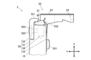
送り台15は、その上部のY軸方向における中央部に送り歯20を着脱可能とする装着部50を備えている。
図2は装着部50と当該装着部50に装着された送り歯20の正面図、図3は側面図、図4は平面図、図5は図2のW−W先に沿った断面図である。
[Feed dog]
The
2 is a front view of the mounting
図示のように、送り歯20は、装着部50に装着するためのカム部30と、上部21において被縫製物の下面に当接して布送り方向に送る歯部22と、釜と縫い針11との間で上糸と下糸とを絡めるために縫い針11が侵入する開口部23と、装着部50に対してX軸方向に送り歯20を位置決めするための位置決め用凹部24とを備えている。
As shown in the figure, the
上記送り歯20は、その上部21が平面視で矩形であり、Y軸方向に沿った五列の歯部22が形成されている。各歯部22は、断面鋸歯状であり、先鋭が上方に向いて、被縫製物の下面に対する接触抵抗を高める形状に形成されている。
送り歯20の下部におけるY軸方向の一端部には前述したカム部30が形成されている。また、送り歯20のY軸方向の中央部から他端部にかけては矩形の開口部23が形成されている。
An
The
カム部30はその長手方向がX軸方向に沿った柱状体であり、X軸方向から見た断面形状が全長に渡って等しくなっている。このカム部30は、歯部22が形成された送り歯20の上部21よりもY軸方向の一端部側(送り方向前側、以下、単に、前側という)に突出すると共に、送り歯20の上部21に対してX軸方向の両方向に突出している。なお、カム部30のX軸方向から見た断面形状については後述する。
The
位置決め用凹部24は、送り歯20の前側の端部から後方に向かって形成された凹溝であり、後述する装着部50の位置決め部材54の円形突起542が嵌合する。位置決め用凹部24は、Y−Z平面に平行な一対の対向面241,241を備え、当該対向面241,241の間隔は円形突起542の直径に等しい。そして、位置決め部材54に対する回転操作により円形突起542がZ軸周りに周回移動すると、当該円形突起542のX軸方向の両端部に対向面241,241が当接していることから、送り歯20全体がX軸方向に沿って移動し、X軸方向について位置を調節することができる。
The
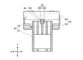
[装着部]
装着部50は、送り歯20のカム部30を載置する土台部51と、上方から当接してカム部30を保持する保持部材52と、土台部51と保持部材52の間にカム部30が挿入される方向に押圧する押圧部材としてのバネ材53と、装着部50に対する送り歯20のX軸方向における位置を位置決めする位置決め部材54とを備えている。
[Mounting part]
The mounting
土台部51は、X軸方向についてカム部30とほぼ等しい幅を有し、その上端部はX−Y平面に沿った平坦面となっている。なお、この平坦面は、後述するカム部30の第一カム面31に面接触する第一受け面511となる(図7参照)。
The
保持部材52は、X軸方向について土台部51と同一幅であってX−Z平面に沿った平板状をなしており、その上端部は後方に向かって屈曲した屈曲部521が形成されている。
保持部材52の屈曲部521は、その下部に土台部51の第一受け面511に対向するX−Y平面に沿った平坦面が形成されている。なお、この平坦面は、その端部が、後述するカム部30の第二カム面32に対して線接触する第二受け面522となる(図7参照)。即ち、この第二受け面522のY軸方向の他端部(送り方向後側、以下、単に、後側という)は、角が丸くX軸周りの周面525(図7参照)となるように形成されており、平坦な第二カム面32に対してX軸方向に沿った線に沿って接触する。
The holding
The
保持部材52は、土台部51の前側の平面に対してネジ523により取り付けられている。保持部材52はZ軸方向に沿った長穴524を介して土台部51にネジ止めされ、ネジ523を緩めた状態でZ軸方向に沿って位置調節ができ、第一受け面511と第二受け面522とのZ軸方向の間隔を調節することができる。
The holding
バネ材53は、その下部が土台部51の後側の平面に対してネジ531により取り付けられている。また、バネ材53は、上部が二又に分岐しており、それぞれの上端部に前方に凸となるように屈曲形成された圧接部532が形成されている。そして、これらの圧接部532は、後述する送り歯20のカム部30の第三カム面33(図7参照)のX軸方向の両端部に個別に圧接し、カム部30を所定方向に押圧している。
The lower portion of the
位置決め部材54は、図5に示すように、土台部51の第一受け面511から下方に向かって設けられた円形の有底穴512に挿入される円柱状の本体部541と、当該本体部541の上端面から上方に突設された円形突起542を備えている。
本体部541は、有底穴512に挿入された状態において内部で回転可能である。また、本体部541の上端面は、有底穴512に挿入された状態において、第一受け面511よりも僅かに低くなるように設定されている。
As shown in FIG. 5, the positioning
The
円形突起542は、円柱状であって本体部541に対して偏心している。また、その上端面には位置決め部材54を回転させるためのドライバー用の−(マイナス)溝が形成されている。前述したように、この円形突起542は、図6に示すように、送り歯20の位置決め用凹部24の一対の対向面241,241の間に配設され、位置決め部材54の回転操作により、本体部541の中心線周りに円形突起542が周回移動を行い、その際のX軸方向の変位を送り歯20に付与し、当該送り歯20のX軸方向の位置調節を可能とする。
また、この位置決め部材54を挿入する有底穴512に対して、土台部51の前面から貫通するネジ穴513が形成されており、当該ネジ穴513には頭無しネジ55が螺入されている。この頭無しネジ55は螺入により位置決め部材54の本体部541の外周面に当接し、位置決め部材54を固定することにより送り歯20の調節後の位置を維持する。
The
A
[カム部による送り歯の着脱構造]
図7はカム部30に対する周囲からの支持状態を示す説明図である。
カム部30は、その底部において装着部50の第一受け面511に面接触する平坦な第一カム面31と、装着部50の第二受け面522の端部に対して、その上部においてカム部30が挿入される挿入方向(Y軸方向)に直交する方向(X軸方向)に沿った線による線接触を行う第二カム面32と、バネ材53の圧接部532に押圧される第三カム面33とを備えている。
[Mounting structure of feed dog by cam part]
FIG. 7 is an explanatory view showing a support state of the
The
第一カム面31は、水平且つ平坦であり、その前側(挿入方向)の端部にX軸方向から見た断面形状がX軸回りの円弧状となる第一の連続面34を備えている。また、第一カム面31の後側の端部には当該第一カム面31と第三カム面33とに連なり、X軸方向から見た断面形状がX軸回りの円弧状となる第二の連続面35が形成されている。
第一カム面31は装着部50の第一受け面511に面接触することにより、送り歯20の上端部を水平に維持することができる。
The
The
第二カム面32は平坦であって上方を向いており、水平面をX軸周りに傾斜させた前傾の傾斜面となっている。この前傾の傾斜により、第二カム面32は、装着部50の第二受け面522の後端部の周面525に対してX軸方向に沿った線による線接触状態となる。
The
第三カム面33は、カム部30の後端部に形成され、平坦であって、X−Z平面に対して上部が前寄りとなるようにX軸回りに傾斜している。そして、この第三カム面33に対して前方に弾性力を生じるバネ材53の圧接部532が圧接している。
このバネ材53により、カム部30は第三カム面33に垂直な押圧力Fが入力される。このバネ材53による押圧力Fは、第一カム面31が第一受け面511を押圧する方向(Z軸方向)の力Fzとカム部30が第一受け面511と第二受け面522の間へ挿入される方向(Y軸方向)の力Fyとに成分分けが可能である。
つまり、上記二方向に成分分けが可能な方向の押圧力Fが第三カム面33に入力されることにより、第一カム面31が第一受け面511に面接触した状態と第二カム面32が第二受け面522の端部に線接触した状態とが維持され、送り歯20を適正な向きでY軸方向及びZ軸方向について適正な位置に保持することができるようになっている。
なお、送り歯20のX軸方向の適正な位置決めは、送り歯20の位置決め用凹部24と位置決め部材54とにより行われている。
The
Due to the
That is, when the pressing force F in the direction in which the components can be divided into the two directions is input to the
Note that proper positioning of the
[送り歯の着脱動作]
図8は送り歯の着脱動作を示す動作説明図である。図示のように、送り歯20はカム部30とは逆側の端部(後端部)を上方に引き上げることで、工具やネジ等の部品の取り外し作業を伴うことなく送り歯20を送り台15から取り外すことができる。
即ち、送り歯20の後端部に上方の引き上げ力を加えると、カム部30の第一の連続面34を支点として送り歯20全体が反時計回りに回動する。その際、第三カム面33の傾斜によりバネ材53の圧接部532は後方に押し戻されるが、カム部30の回動には梃子の作用が働くので、比較的容易に回動させることができる。また、カム部30の第一のカム面31と第三カム面33との間には第二の連続面35が形成されているので、第一カム面31と第三カム面33との間に角がある場合に比べて、バネ材53の圧接部532が容易に第二の連続面35を通過することができる。
また、第二カム面32は、保持部材52の屈曲部521の先端部に当接してカム部30が後退移動するが、第一の連続面34により第一受け面511の上を円滑に滑らせることができ、カム部30を第一受け面511と第二受け面522の間から引き出すことができる。
これにより、送り歯20は、送り台15から容易に取り外すことができる。
[Feed dog attachment / detachment]
FIG. 8 is an operation explanatory view showing a feed dog attaching / detaching operation. As shown in the figure, the
That is, when an upward pulling force is applied to the rear end portion of the
Further, the
Thereby, the
また、送り歯20を送り台15に取り付ける場合には、取り外しと全く逆の動作により行うことができる。即ち、送り歯20の後端部が上方を向くように傾けた状態で、カム部30の先端を保持部材52とバネ材53との間に挿入し、第一受け面511にカム部30の第一の連続面34を当接させると共に当該連続面34に従って送り歯20全体を後端部が下降するように時計回りに回動させる。
これにより、カム部30の先端部が第一受け面511と第二受け面522との間に徐々に入り込む。この時、カム部30の第二の連続面35はバネ材53の圧接部532に当接し、当該圧接部532を後方に押しながら当該圧接部532を通過する。そして、第二の連続面35が通過後、バネ材53の圧接部532は、第三カム面33に圧接する。これにより、カム部30は前方と下方に向かって押圧され、第一カム面31が第一受け面511に面接触し、第二カム面32が第二受け面522の後端部の周面525に線接触した状態で停止する。これにより、送り歯20はY軸方向とZ軸方向について適正な位置に位置決めされ、また、送り歯20の上端部が水平となる様に適正な向きに保持される。
またこの時、送り歯20の位置決め用凹部24に位置決め部材54の円形突起542が嵌合するように送り歯20を導くことによりX軸方向についても送り歯20は適正な位置に位置決めされる。
Further, when the
As a result, the tip of the
At this time, the
[直線縫い用の送り歯]
千鳥縫い用の送り歯20と交換する直線縫い用の送り歯20Aを図9に示す。この送り歯20Aについて送り歯20と同一の構成については同符号を付して重複する説明は省略する。
この送り歯20Aは、送り歯20と同一のカム部30を備え、上部21Aは上部21よりもX軸方向の幅が狭く形成されている。これにより、歯部22は五本から三本に減じられており、また、上部21Aの幅の減少に伴い、開口部23Aの幅も狭くなっている。
この送り歯20Aは、カム部30を備えるので、送り歯20と同様に、送り台15に対する取り付け及び取り外しを容易に行うことができ、送り歯20と送り歯20Aとの交換を容易に行うことができる。
[Feed dog for linear stitching]
FIG. 9 shows a
The
Since the
[実施形態の技術的効果]
上記ミシン10は、被縫製物の送り方向に沿った動作を付与される送り台15と、針板13の上の被縫製物を送る送り歯20(又は20A)とを備え、送り台15に送り歯20(又は20A)を分離可能に装着する装着部50を設けている。
このため、縫いの種類に適した送り歯20,20Aへの交換を行うことができ、縫い品質の向上を図ることが可能となる。
[Technical effects of the embodiment]
The
For this reason, the
また、送り歯20,20Aは、装着部50に装着するためのカム部30を備え、装着部50は、カム部30が挿入される対向状態の第一受け面511及び第二受け面522と、これらに挿入されたカム部30を挿入方向に押圧する押圧部材としてのバネ材53とを備え、カム部30は、平坦な第一受け面511に面接触する平坦な第一カム面31と、第二受け面522の後端部の周面525に対して、カム部30が挿入される挿入方向(Y軸方向)に直交する方向(X軸方向)に沿った線による線接触を行う第二カム面32と、バネ材53に押圧される第三カム面33とを備え、第三カム面33に対してバネ材53が押圧する方向は、第一カム面31が第一受け面511を押圧する方向(Z軸方向)とカム部30が第一受け面511と第二受け面522との間へ挿入される方向(Y軸方向)とに成分分けが可能な方向である。
これにより、第一のカム面31の面接触状態と第二カム面32の線接触状態がバネ材53の押圧力で維持され、送り歯20,20AをY軸方向及びZ軸方向について適正な位置に保持すると共に送り歯20が傾くことなく適正な姿勢を保持することが可能となる。
また、カム部30と装着部50による上記の支持構造とにより、送り歯20,20Aを取り外しと取り付けとを送り歯20,20Aの手操作による回動により工具などを使うことなく容易に行うことが可能となる。
Further, the
As a result, the surface contact state of the
Further, with the above-described support structure by the
また、カム部30は、送り歯20,20Aにおける挿入方向の端部に設けているので、回動操作による送り歯20,20Aの装着に梃子の原理を利用することができ、強力なバネ材53で送り歯20,20Aを保持する場合でも、装着を容易に行うことが可能となる。
Further, since the
また、送り歯20,20Aは、装着部50に対するカム部30の挿入方向と送り歯20,20Aによる被縫製物の送り方向とが平行となっている。
これにより、縫製時において被縫製物からの送りの抗力によって送り歯20の向きの変動が生じ難く、良好な送り動作を行うことが可能となる。
Further, in the
Thereby, the direction of the
また、装着部50は、第一受け面511に平行であって挿入方向に交差する方向(X軸方向)について、送り歯20,20Aを装着部50に対して位置決めする位置決め部材54を備えている。
従って、送り歯20,20Aの取り付けの際に、X軸方向にも適正な位置決めを行うことが可能となる。
In addition, the mounting
Accordingly, when the
また、カム部30は、第一カム面31の挿入方向の端部(前側の端部)に当該第一カム面31に連なる断面円弧状の第一の連続面34を有しているので、送り歯20,20Aの着脱の際に当該送り歯20,20Aを第一の連続面34に従って回動させることができ、装着作業を円滑に行うことが可能となる。
また、カム部30の先端部を第一受け面511と第二受け面522との間に挿入又は引き出す際に、第一の連続面34が第一受け面511に対して円滑に摺動するので、装着作業をさらに円滑に行うことが可能となる。
Further, the
Further, when the leading end portion of the
また、バネ材53は、第三カム面33に圧接する圧接部532を備え、カム部30は、第一カム面31及び第三カム面33に連なる断面円弧状の第二の連続面35を有するので、送り歯20,20Aの着脱の際に、第一カム面31及び第三カム面33の間が圧接部532を通過する際に円滑に通過することができ、装着作業をさらに円滑に行うことが可能となる。
Further, the
[その他]
上記実施形態では、押圧部材としてバネ材53を例示したが、カム部30の第三カム面33を押圧することができれば他の部材或いは他の機構を利用しても良い。
例えば、進出可能な爪を備えたラッチ機構を送り台15の土台部51に設け、突出する方向に弾性的に押圧された爪をカム部30の第三カム面33に押しつけるように設けても良い。この場合、爪を弾性力に抗して後退させることで送り歯20,20Aの着脱を行うことができ、また、爪の押圧力が送り歯20,20Aを装着部50に保持することを可能とする。つまり、バネ材53と同様に機能させることができる。
[Others]
In the above embodiment, the
For example, a latch mechanism having an advanceable claw may be provided on the
また、図10に示すように、押圧部材として、第三カム面33に圧接する位置と第三カム面33から退避した位置とに位置切り替え可能なレバー部材53Bを使用しても良い。
即ち、レバー部材53Bは、基端部が土台部51の後側の平面に対してY軸回りに回動可能に支持され、回動端部が土台部51の側方の外側を向いた状態(退避位置、実線で図示)と90°回動して起立した状態(圧接位置、二点鎖線で図示)との間で切り替え可能である。
そして、レバー部材53Bの回動端部は、前側に向かって突出し、その突出端部が圧接部532Bとなって第三カム面33に圧接することで、カム部30を前方及び下方に押圧する構成としても良い。
この時、レバー部材53Bの回動端部の圧接部532Bは、実線で図示するように、退避位置から圧接位置に向かうにつれて徐々に前方への突出量が多くなる部分が当接するように、先端部の当接面形状を湾曲面又は傾斜面とすることが望ましい。これにより、レバー部材53Bの回動に応じてカム部30の第三カム面33を徐々に前方に押圧することができる。なお、図10では片側の第三カム面33に当接するレバー部材53Bしか図示されていないが、もう一方の第三カム面33に当接するレバー部材が設けられている。なお、もう一方のレバー部材はその先端部の当接面形状の湾曲又は傾斜の方向が対称とすることが望ましい。
As shown in FIG. 10, a
That is, the
Then, the rotating end portion of the
At this time, the
2 送り機構
10 ミシン
11 縫い針
12 針棒
13 針板
14 布押さえ
15 送り台
20,20A 送り歯
24 位置決め 用凹部
30 カム部
31 第一カム面
32 第二カム面
33 第三カム面
34 第一の連続面
35 第二の連続面
50 装着部
53 バネ材(押圧部材)
53B レバー部材(押圧部材)
54 位置決め部材
511 第一受け面
522 第二受け面
525 第二受け面の後端部の周面
532,532B 圧接部
2
53B Lever member (pressing member)
54
Claims (10)
被縫製物の送り方向に沿った動作を付与される送り台と、前記針板の上の被縫製物を送る送り歯とを備え、
前記送り台に前記送り歯を分離可能に装着する装着部を備え、
前記送り歯は、前記装着部に装着するためのカム部を備え、
前記装着部は、前記カム部が挿入される対向状態の第一受け面及び第二受け面と、これらに挿入された前記カム部を挿入方向に押圧する押圧部材とを備え、
前記カム部は、
平坦な前記第一受け面に面接触する平坦な第一カム面と、
前記第二受け面の端部に対して、前記カム部が挿入される挿入方向に直交する方向に沿った線による線接触を行う第二カム面と、
前記押圧部材に押圧される第三カム面と、を備えたことを特徴とするミシン。 In the sewing machine that can replace the cloth presser and throat plate according to the type of sewing,
A feed base to which an operation along the feed direction of the workpiece is provided, and a feed dog that feeds the workpiece on the needle plate,
A mounting portion for detachably mounting the feed dog on the feed base;
The feed dog includes a cam portion for mounting on the mounting portion,
The mounting portion includes a first receiving surface and a second receiving surface in an opposed state into which the cam portion is inserted, and a pressing member that presses the cam portion inserted therein in the inserting direction.
The cam portion is
A flat first cam surface in surface contact with the flat first receiving surface;
A second cam surface that performs line contact with a line along a direction orthogonal to an insertion direction in which the cam portion is inserted, with respect to an end portion of the second receiving surface;
And a third cam surface pressed by the pressing member.
前記カム部は、前記第一カム面及び前記第三カム面に連なる断面円弧状の第二の連続面を有することを特徴とする請求項1から6のいずれか一項に記載のミシン。 The pressing member includes a pressing portion that presses against the third cam surface,
The sewing machine according to any one of claims 1 to 6, wherein the cam portion has a second continuous surface having an arcuate cross section that is continuous with the first cam surface and the third cam surface.
Priority Applications (3)
| Application Number | Priority Date | Filing Date | Title |
|---|---|---|---|
| JP2015001263A JP6441084B2 (en) | 2015-01-07 | 2015-01-07 | sewing machine |
| US14/986,803 US10415167B2 (en) | 2015-01-07 | 2016-01-04 | Sewing machine |
| CN201610009014.9A CN105755684B (en) | 2015-01-07 | 2016-01-07 | Sewing machine |
Applications Claiming Priority (1)
| Application Number | Priority Date | Filing Date | Title |
|---|---|---|---|
| JP2015001263A JP6441084B2 (en) | 2015-01-07 | 2015-01-07 | sewing machine |
Publications (2)
| Publication Number | Publication Date |
|---|---|
| JP2016123772A true JP2016123772A (en) | 2016-07-11 |
| JP6441084B2 JP6441084B2 (en) | 2018-12-19 |
Family
ID=56286189
Family Applications (1)
| Application Number | Title | Priority Date | Filing Date |
|---|---|---|---|
| JP2015001263A Active JP6441084B2 (en) | 2015-01-07 | 2015-01-07 | sewing machine |
Country Status (3)
| Country | Link |
|---|---|
| US (1) | US10415167B2 (en) |
| JP (1) | JP6441084B2 (en) |
| CN (1) | CN105755684B (en) |
Cited By (2)
| Publication number | Priority date | Publication date | Assignee | Title |
|---|---|---|---|---|
| US10202716B2 (en) | 2016-09-16 | 2019-02-12 | Janome Sewing Machine Co., Ltd. | Sewing machine |
| CN112095232A (en) * | 2020-09-21 | 2020-12-18 | 福建省华昂体育用品有限公司 | Novel double-needle high-head sewing machine |
Families Citing this family (1)
| Publication number | Priority date | Publication date | Assignee | Title |
|---|---|---|---|---|
| JP7479937B2 (en) | 2020-06-01 | 2024-05-09 | 株式会社ジャノメ | Feed dog attachment/detachment mechanism and sewing machine |
Citations (3)
| Publication number | Priority date | Publication date | Assignee | Title |
|---|---|---|---|---|
| JPS4716268Y1 (en) * | 1969-11-11 | 1972-06-08 | ||
| JPS4716267Y1 (en) * | 1969-11-11 | 1972-06-08 | ||
| JPS4984253U (en) * | 1972-11-11 | 1974-07-22 |
Family Cites Families (12)
| Publication number | Priority date | Publication date | Assignee | Title |
|---|---|---|---|---|
| US1899816A (en) * | 1927-02-25 | 1933-02-28 | Union Special Maschinenfab | Feeding mechanism for sewing machines |
| US2882846A (en) * | 1956-05-28 | 1959-04-21 | Angelica Uniform Company | Feed dog for sewing machines |
| DE1017451B (en) * | 1956-07-17 | 1957-10-10 | Pfaff Ag G M | Fabric feed device for double chain stitch sewing machines |
| FR2207495A5 (en) | 1972-11-21 | 1974-06-14 | Ibm | |
| US3980032A (en) | 1975-04-17 | 1976-09-14 | Union Special Maschinenfabrik G.M.B.H. | Sewing machine having automatic feed control system |
| DE2901709A1 (en) * | 1978-01-30 | 1979-08-02 | Metalplast Srl | ACTUATION MECHANISM FOR HOOKS AND THE FABRIC TRANSPORTER OF A PORTABLE SEWING MACHINE |
| CN1055976C (en) | 1995-01-18 | 2000-08-30 | 重机公司 | Bobbin exchanger |
| JP3990757B2 (en) | 1996-10-18 | 2007-10-17 | Juki株式会社 | Zigzag sewing machine |
| CN2501895Y (en) | 2001-07-10 | 2002-07-24 | 中捷缝纫机股份有限公司 | Sewing machine with movable feed-dog |
| JP2004174120A (en) | 2002-11-29 | 2004-06-24 | Juki Corp | Sewing machine feeder |
| JP2010194159A (en) * | 2009-02-26 | 2010-09-09 | Brother Ind Ltd | Sewing machine |
| CN202202115U (en) | 2011-06-10 | 2012-04-25 | 名匠缝纫机股份有限公司 | Adjustable feed dog for four-needle six-thread sewing machine |
-
2015
- 2015-01-07 JP JP2015001263A patent/JP6441084B2/en active Active
-
2016
- 2016-01-04 US US14/986,803 patent/US10415167B2/en active Active
- 2016-01-07 CN CN201610009014.9A patent/CN105755684B/en active Active
Patent Citations (3)
| Publication number | Priority date | Publication date | Assignee | Title |
|---|---|---|---|---|
| JPS4716268Y1 (en) * | 1969-11-11 | 1972-06-08 | ||
| JPS4716267Y1 (en) * | 1969-11-11 | 1972-06-08 | ||
| JPS4984253U (en) * | 1972-11-11 | 1974-07-22 |
Cited By (2)
| Publication number | Priority date | Publication date | Assignee | Title |
|---|---|---|---|---|
| US10202716B2 (en) | 2016-09-16 | 2019-02-12 | Janome Sewing Machine Co., Ltd. | Sewing machine |
| CN112095232A (en) * | 2020-09-21 | 2020-12-18 | 福建省华昂体育用品有限公司 | Novel double-needle high-head sewing machine |
Also Published As
| Publication number | Publication date |
|---|---|
| US20160194797A1 (en) | 2016-07-07 |
| US10415167B2 (en) | 2019-09-17 |
| CN105755684B (en) | 2020-08-04 |
| JP6441084B2 (en) | 2018-12-19 |
| CN105755684A (en) | 2016-07-13 |
Similar Documents
| Publication | Publication Date | Title |
|---|---|---|
| US8438984B2 (en) | Embroidery frame | |
| JP6441084B2 (en) | sewing machine | |
| JP6102569B2 (en) | Embroidery frame and sewing machine | |
| JP2005052571A (en) | Sequin sewing device | |
| TWI411716B (en) | Sewing machine yarn breaking device | |
| US10954616B2 (en) | Embroidery frame transport device and embroidery frame | |
| WO2019131040A1 (en) | Embroidery frame transfer device and sewing machine | |
| JP4492385B2 (en) | Eyelet hole sewing machine | |
| JP2007014600A (en) | Sequin feeder | |
| JP2012085957A (en) | Mechanism for attaching presser of sewing machine, and sewing machine | |
| JP2007307275A (en) | Top feed device for sewing machine | |
| JP2017000300A (en) | Clamp mechanism and sewing machine having the same | |
| CN106192227B (en) | Feed dog attaching and detaching device and sewing machine provided with same | |
| JP4747742B2 (en) | Sewing machine needle bar drive device and sewing machine | |
| CN1869308B (en) | Looper seat for keyhole sewing machine | |
| JP4660268B2 (en) | Button carrier | |
| US1359858A (en) | Work-holder for button-sewing machines | |
| JP2020156984A (en) | Cloth cutter and sewing machine | |
| JP7354882B2 (en) | Presser foot mounting structure | |
| JP2017148180A (en) | sewing machine | |
| JP2017148179A (en) | Clamp assist device | |
| US2655119A (en) | Ornamental stitching attachment for sewing machines | |
| US2676558A (en) | Ornamental stitching attachment for sewing machines | |
| JP2009268724A (en) | Vertical swing looper pull-out device of sewing machine | |
| JP2010068837A (en) | Sewing machine |
Legal Events
| Date | Code | Title | Description |
|---|---|---|---|
| A621 | Written request for application examination |
Free format text: JAPANESE INTERMEDIATE CODE: A621 Effective date: 20171220 |
|
| A977 | Report on retrieval |
Free format text: JAPANESE INTERMEDIATE CODE: A971007 Effective date: 20180816 |
|
| A131 | Notification of reasons for refusal |
Free format text: JAPANESE INTERMEDIATE CODE: A131 Effective date: 20180828 |
|
| A521 | Request for written amendment filed |
Free format text: JAPANESE INTERMEDIATE CODE: A523 Effective date: 20181019 |
|
| TRDD | Decision of grant or rejection written | ||
| A01 | Written decision to grant a patent or to grant a registration (utility model) |
Free format text: JAPANESE INTERMEDIATE CODE: A01 Effective date: 20181030 |
|
| A61 | First payment of annual fees (during grant procedure) |
Free format text: JAPANESE INTERMEDIATE CODE: A61 Effective date: 20181121 |
|
| R150 | Certificate of patent or registration of utility model |
Ref document number: 6441084 Country of ref document: JP Free format text: JAPANESE INTERMEDIATE CODE: R150 |