JP2016123765A - Chemical volatilizer - Google Patents
Chemical volatilizer Download PDFInfo
- Publication number
- JP2016123765A JP2016123765A JP2015001139A JP2015001139A JP2016123765A JP 2016123765 A JP2016123765 A JP 2016123765A JP 2015001139 A JP2015001139 A JP 2015001139A JP 2015001139 A JP2015001139 A JP 2015001139A JP 2016123765 A JP2016123765 A JP 2016123765A
- Authority
- JP
- Japan
- Prior art keywords
- support
- drug
- drug container
- neck
- main body
- Prior art date
- Legal status (The legal status is an assumption and is not a legal conclusion. Google has not performed a legal analysis and makes no representation as to the accuracy of the status listed.)
- Granted
Links
Images
Landscapes
- Packaging Of Annular Or Rod-Shaped Articles, Wearing Apparel, Cassettes, Or The Like (AREA)
- Air-Conditioning For Vehicles (AREA)
- Disinfection, Sterilisation Or Deodorisation Of Air (AREA)
Abstract
【課題】薬剤を吸液芯によって吸い上げるタイプの薬剤揮散器であっても、薬剤がこぼれるのを防止することができる、薬剤揮散器を提供する。
【解決手段】本発明に係る薬剤揮散器は、上部に開口を有し、液状の薬剤が収容された薬剤容器と、薬剤容器の開口に差し込まれる吸液芯と、薬剤容器を支持するとともに、取付対象物に取り付けられる支持体と、を備え、支持体は、開口の軸線方向に対する径方向外方から、薬剤容器を挟むように保持する保持部を備えている。
【選択図】図1Disclosed is a chemical volatilizer that can prevent a chemical from spilling even if the chemical volatilizer is a type of chemical volatilizer that uses a liquid absorbent wick.
A drug volatilizer according to the present invention has an opening in the upper part, a drug container containing a liquid drug, a liquid absorption core inserted into the opening of the drug container, and the drug container, A support that is attached to the attachment object, and the support includes a holding portion that holds the medicine container from outside in the radial direction with respect to the axial direction of the opening.
[Selection] Figure 1
Description
本発明は、薬剤揮散器に関する。 The present invention relates to a chemical volatilizer.
従来より、芳香剤等の薬剤が揮散される種々の形態の薬剤揮散器が提案されている。その中で、振動が生じる場所、例えば、車内で用いる薬剤揮散器も提案されているが、このような薬剤揮散器は収容された液状の薬剤がこぼれてしまうという問題があった。そのため、車内で用いる薬剤揮散器としては、液状の薬剤を用いないゲルタイプや、振動によっても薬剤が漏れにくいメンブレインタイプが用いられることが多い。メンブレインタイプとは、気体を通す膜を用い、この膜を介して揮散した薬剤を外部に放出するものである(例えば、特許文献1)。 Conventionally, various forms of chemical volatilizers have been proposed in which chemicals such as fragrances are volatilized. Among them, a chemical volatilizer used in a place where vibration occurs, for example, in a vehicle, has been proposed. However, such a chemical volatilizer has a problem that a liquid chemical contained therein is spilled. For this reason, as a chemical volatilizer used in a vehicle, a gel type that does not use a liquid chemical or a membrane type that does not easily leak even by vibrations is often used. The membrane type is a type in which a gas-permeable membrane is used and a chemical volatilized through the membrane is released to the outside (for example, Patent Document 1).
しかしながら、メンブレインタイプでは、使用できる薬剤が限定されるという問題があった。例えば、高温の環境で用いる場合には、短期間で揮散してしまうような薬剤しか用いることができなかった。そこで、温度等に関わらず、種々の環境で利用可能な薬剤を用いる場合には、次のような薬剤揮散器が考えられる。すなわち、車内に取り付けられた支持体に薬剤容器を支持させるとともに、薬剤容器に収容される薬剤を吸液芯によって吸い上げ、揮散した薬剤を外部に放出するタイプの薬剤揮散器が考えられる。しかしながら、このタイプの薬剤揮散器は、振動が発生する場所で使用すると、支持体から薬剤容器が離脱し、薬剤がこぼれるという問題があった。本発明は、この問題を解決するためになされたものであり、薬剤を吸液芯によって吸い上げるタイプの薬剤揮散器であっても、薬剤がこぼれるのを防止することができる、薬剤揮散器を提供することを目的とする。 However, the membrane type has a problem that the drugs that can be used are limited. For example, when used in a high-temperature environment, only chemicals that would volatilize in a short period of time could be used. Therefore, the following chemical volatilizers can be considered when using chemicals that can be used in various environments regardless of temperature. That is, a drug volatilizer of a type that supports a drug container on a support attached in the vehicle, sucks up the drug contained in the drug container with a liquid absorbent core, and discharges the volatilized drug to the outside. However, when this type of chemical volatilizer is used in a place where vibration is generated, there is a problem that the chemical container is detached from the support and the chemical spills. The present invention has been made to solve this problem, and provides a chemical volatilizer that can prevent the chemical from spilling even if the chemical volatilizer is a type of chemical volatilizer that sucks up a drug by a liquid absorbent core. The purpose is to do.
本発明に係る薬剤揮散器は、上部に開口を有し、液状の薬剤が収容された薬剤容器と、前記薬剤容器の開口に差し込まれる吸液芯と、前記薬剤容器を支持するとともに、取付対象物に取り付けられる支持体と、を備え、前記支持体は、前記開口の軸線方向に対する径方向外方から、前記薬剤容器を挟むように保持する保持部を備えている。 The drug volatilizer according to the present invention has an opening in the upper part, a drug container in which a liquid drug is accommodated, a liquid absorption core inserted into the opening of the drug container, the drug container, and an attachment target A support that is attached to an object, and the support includes a holding unit that holds the drug container from outside in the radial direction with respect to the axial direction of the opening.
この構成によれば、薬剤を収容する薬剤容器が、支持体において、開口の軸線方向に対する径方向外方から挟むように保持されているため、薬剤容器が径方向、つまり横方向からの振動を受けても、薬剤容器が支持体から離脱するのを防止することができる。その結果、薬剤容器から薬剤がこぼれるのを防止することができる。 According to this configuration, since the medicine container that contains the medicine is held on the support so as to be sandwiched from outside in the radial direction with respect to the axial direction of the opening, the medicine container vibrates in the radial direction, that is, in the lateral direction. Even if it receives, it can prevent that a chemical | medical agent container detaches | leaves from a support body. As a result, it is possible to prevent the medicine from spilling from the medicine container.
上記薬剤揮散器において、保持部は、薬剤容器のいずれの位置を保持するように構成されてもよいが、例えば、前記薬剤容器が、前記開口が形成された首部と、前記首部よりも外形が大きく、当該首部が連結される本体部と、を備え、前記保持部が、前記首部を保持するように構成することができる。 In the drug volatilizer, the holding unit may be configured to hold any position of the drug container. For example, the drug container has a neck part in which the opening is formed and an outer shape that is larger than the neck part. A main body portion to which the neck portion is coupled, and the holding portion can be configured to hold the neck portion.
このとき、前記首部の外周面に、突部を形成し、前記突部と前記本体部との間の隙間に、前記保持部が係合するように構成することができる。こうすることで、薬剤容器の軸線方向の移動が拘束されるため、薬剤容器が軸線方向、つまり上下方向の振動を受けても、支持体から離脱するのを防止することができる。 At this time, a protrusion can be formed on the outer peripheral surface of the neck, and the holding portion can be engaged with a gap between the protrusion and the main body. By doing so, since the movement of the drug container in the axial direction is restricted, it is possible to prevent the drug container from being detached from the support body even when the drug container receives vibration in the axial direction, that is, the vertical direction.
上記各薬剤揮散器において、前記支持体は、前記保持部が設けられている側とは反対側から前記薬剤容器を覆う第1壁面と、前記吸液芯が差し込まれた前記開口側を覆う第2壁面と、を備えたカバーをさらに備え、前記第2壁面は、気体が通過可能に構成することができる。 In each of the drug volatilizers, the support includes a first wall surface that covers the drug container from a side opposite to a side on which the holding unit is provided, and a first cover that covers the opening side into which the liquid absorption core is inserted. A cover provided with two wall surfaces is further provided, and the second wall surface can be configured to allow gas to pass therethrough.
この構成により、次の効果を得ることができる。すなわち、第1壁面によって、薬剤容器が保持部から離れる方向に、支持体から離脱するのを防止することができる。また、第2壁面によって、吸液芯が薬剤容器から離脱するのを防止することができる。但し、第2壁面は、気体が通過可能に構成されているため、揮散した薬剤を外部に放出することができる。また、カバーを設けることで、薬剤容器を隠すことができ、例えば、第1壁面に装飾を施せば、製品の装飾性を高めることができる。 With this configuration, the following effects can be obtained. That is, the first wall surface can prevent the medicine container from being detached from the support body in the direction away from the holding portion. Further, the second wall surface can prevent the liquid absorbent core from being detached from the drug container. However, since the second wall surface is configured to allow gas to pass through, the volatilized drug can be released to the outside. Further, by providing the cover, the medicine container can be hidden. For example, if the first wall surface is decorated, the decorativeness of the product can be enhanced.
上記各薬剤揮散器において、前記薬剤容器は、前記開口が形成された首部と、前記首部よりも外形が大きく、当該首部が連結される本体部と、を備え、前記保持部は、前記首部を保持するように構成されており、前記支持体は、前記薬剤容器の重心Gと対応する上下方向の位置において、前記本体部の外周面と当接する第1支持部と、前記第1支持部に連結され、当該第1支持部よりも下方において、前記本体部と隙間を空けて配置される第2支持部と、を備えることができる。 In each of the drug volatilizers, the drug container includes a neck part in which the opening is formed, and a main body part having an outer shape larger than the neck part and connected to the neck part, and the holding part includes the neck part. The support body is configured to hold a first support part in contact with an outer peripheral surface of the main body part at a vertical position corresponding to the center of gravity G of the drug container; and the first support part. And a second support portion that is connected and disposed below the first support portion with a gap therebetween.
この構成によれば、薬剤容器の本体部の外周面全体が支持体に支持されているのでなく、薬剤容器は、支持体のうち、第1支持部と当接し、第2支持部とは隙間を空けている。そのため、薬剤容器が振動を受けても、その振動の少なくとも一部を第2支持部との隙間で吸収することができる。その結果、振動を受けたとき、薬剤容器が支持体からの衝撃で破損するのを防止することができる。また、第1支持部は、薬剤容器の重心Gと対応する上下方向の位置において、薬剤容器の本体部の外周面と当接しているため、振動を受けたとき(特に薬剤容器内の薬剤の残量が少なくなったとき)でも、支持体に対して大きく揺れるのを防止することができる。 According to this configuration, the entire outer peripheral surface of the main body portion of the drug container is not supported by the support body, but the drug container is in contact with the first support portion of the support body, and is not spaced from the second support portion. Is open. Therefore, even if the medicine container receives vibration, at least part of the vibration can be absorbed by the gap with the second support portion. As a result, when receiving vibration, the medicine container can be prevented from being damaged by the impact from the support. Further, since the first support portion is in contact with the outer peripheral surface of the main body portion of the drug container at the vertical position corresponding to the center of gravity G of the drug container, the first support portion receives vibration (particularly the drug in the drug container). Even when the remaining amount is low), it can be prevented that the support is greatly shaken.
上記各薬剤揮散器において、前記薬剤容器は、前記開口が形成された首部と、前記首部よりも外形が大きく、当該首部が連結される本体部と、を備え、前記保持部は、前記首部を保持するように構成されており、前記支持体は、上下方向に延び、前記保持部が前記首部に向けて延びるように連結されるとともに、少なくとも一部が前記本体部の側面と当接する、上下支持部と、前記上下支持部の下端部に連結され、前記保持部と同じ方向に、前記本体部の底面を支持するように延びる底面支持部と、を備えることができる。 In each of the drug volatilizers, the drug container includes a neck part in which the opening is formed, and a main body part having an outer shape larger than the neck part and connected to the neck part, and the holding part includes the neck part. The support is configured to extend vertically, and is connected so that the holding portion extends toward the neck, and at least a part of the support contacts the side surface of the main body. A support part and a bottom face support part connected to the lower end part of the upper and lower support parts and extending so as to support the bottom face of the main body part in the same direction as the holding part can be provided.
この構成によれば、薬剤容器の本体部は、保持部と底面支持部とで上下方向から挟むように支持されるため、薬剤容器を支持体に取り付ける際、上下方向の位置ずれがあれば、本体部は保持部または底面支持部に当たるため、取り付けることができない。したがって、底面支持部は、薬剤容器を支持体に取り付けるためのガイドとして機能する。また、本体部が、保持部と底面支持部とで上下方向から挟むように支持されるため、本体部が斜め上方または斜め下方に向かって離脱するのを防止することができる。 According to this configuration, since the main body portion of the drug container is supported so as to be sandwiched between the holding portion and the bottom surface support portion from above and below, when the drug container is attached to the support, if there is a vertical displacement, Since the main body portion hits the holding portion or the bottom surface supporting portion, it cannot be attached. Therefore, the bottom surface support portion functions as a guide for attaching the drug container to the support. In addition, since the main body portion is supported so as to be sandwiched between the holding portion and the bottom surface support portion from the vertical direction, it is possible to prevent the main body portion from being detached obliquely upward or obliquely downward.
上記各薬剤揮散器においては、支持体を取付対象物に直接取り付けることもできるが、例えば、前記支持体を、取付対象物に取り付けるための固定部を備えることができる。 In each said chemical volatilizer, although a support body can also be directly attached to an attachment target object, the fixing | fixed part for attaching the said support body to an attachment target object can be provided, for example.
また、前記固定部は、前記支持体に対し、停止することなく回転できるように連結することができる。なお、本発明に係る「回転」とは、360度以上の回転のみらならず、半回転などの360度よりも小さい角度での回転を含む。 Moreover, the said fixing | fixed part can be connected with respect to the said support body so that it can rotate, without stopping. The “rotation” according to the present invention includes not only rotation of 360 degrees or more but also rotation at an angle smaller than 360 degrees such as half rotation.
この構成によれば、支持体が振動を受けた場合、支持体は固定部に対して回転するようになっている。したがって、例えば、取付対象物が傾いたとしても、支持体の重心が、支持体と固定部との連結部分の鉛直下方に位置するように、支持体は回転する。そのため、薬剤容器は、開口が上方を向いた状態に維持されるため、薬剤がこぼれるのを防止することができる。 According to this structure, when a support body receives a vibration, a support body rotates with respect to a fixing | fixed part. Therefore, for example, even if the attachment object is tilted, the support rotates so that the center of gravity of the support is positioned vertically below the connecting portion between the support and the fixed portion. Therefore, since the medicine container is maintained in a state in which the opening faces upward, the medicine can be prevented from spilling.
なお、「停止することなく」とは、固定部に対する支持体の回転時に、支持体が抵抗を受けて完全に停止するのを除く意味である。したがって、取付対象物が傾き、支持体が固定部に対して回転するときに、多少の抵抗を受けたとしても、完全に停止することなく、支持体の重心が、支持体と固定部との連結部分の鉛直下方に移動するのであれば、本発明の「停止することなく」に含まれる。 Note that “without stopping” means that the support is completely stopped due to resistance during rotation of the support with respect to the fixed portion. Therefore, even if the object to be mounted is tilted and the support rotates relative to the fixed part, even if it receives some resistance, the center of gravity of the support does not stop between the support and the fixed part without stopping completely. If it moves below the connecting portion vertically, it is included in “without stopping” of the present invention.
上記各薬剤揮散器において、前記薬剤容器は、前記開口の直下に形成された底面と、当該底面の周縁から上方へ延びる外周面と、を備え、前記吸液芯の下端部の少なくとも一部が、前記底面の周縁のいずれかに当接するように構成することができる。 In each of the drug volatilizers, the drug container includes a bottom surface formed immediately below the opening and an outer peripheral surface extending upward from a peripheral edge of the bottom surface, and at least a part of a lower end portion of the liquid absorbent core is provided. , It can be configured to contact any one of the peripheral edges of the bottom surface.
このような薬剤容器においては、外周面を伝って底面に流れた薬剤は、表面張力により底面の周縁に貯まりやすいが、上記のように、吸液芯の下端部の少なくとも一部を、底面の周縁のいずれかに当接するようすれば、側面の周縁に貯まった薬剤も確実に吸い上げることができる。その結果、薬剤の最後まで使い切ることができる。 In such a drug container, the drug that has flowed to the bottom surface along the outer peripheral surface is likely to accumulate at the periphery of the bottom surface due to the surface tension, but as described above, at least a part of the lower end portion of the liquid absorbent core is placed on the bottom surface. If it abuts on one of the peripheral edges, the medicine accumulated on the peripheral edge on the side surface can be sucked up reliably. As a result, the medicine can be used up to the end.
上記各薬剤揮散器において、前記薬剤容器は、底面と、当該底面の周縁から上方に延びる外周面と、を備え、前記薬剤容器の内壁面には、前記底面から前記外周面の少なくとも一部に亘って延びる少なくとも1つの突条又は溝が形成されているものとすることができる。 In each of the drug volatilizers, the drug container includes a bottom surface and an outer peripheral surface extending upward from a peripheral edge of the bottom surface, and the inner wall surface of the drug container has at least a part of the outer peripheral surface from the bottom surface. At least one ridge or groove extending across may be formed.
このような突条又は溝が設けられていると、薬剤は突条又は溝を伝うことで、底面まで流れ落ちやすくなる。その結果、吸液芯によって流れ落ちた薬剤を吸い上げやすくなる。 When such protrusions or grooves are provided, the drug easily flows down to the bottom surface by passing through the protrusions or grooves. As a result, it becomes easy to suck up the medicine that has flowed down by the liquid absorbent core.
上記各薬剤揮散器において、前記薬剤容器は、底面と、当該底面の周縁から上方に延びる外周面と、を備え、前記薬剤容器の内壁面には、前記外周面から前記開口に向かって延びる少なくとも1つの突条又は溝が形成されているものとすることができる。 In each of the drug volatilizers, the drug container includes a bottom surface and an outer peripheral surface extending upward from a peripheral edge of the bottom surface, and at least an inner wall surface of the drug container extends from the outer peripheral surface toward the opening. One ridge or groove may be formed.
このような突条又は溝を設けると、例えば、薬剤容器を逆さに向けたとき、薬剤は外周面を伝って開口側に向かうが、薬剤は、突条又は溝を伝って、開口へと確実に流れるため、開口に刺し込まれた吸液芯に確実に吸引させることができる。 When such a ridge or groove is provided, for example, when the medicine container is turned upside down, the medicine is directed to the opening side along the outer peripheral surface, but the medicine is surely directed to the opening through the ridge or groove. Therefore, the liquid-absorbing core inserted into the opening can be surely sucked.
本発明に係る薬剤揮散器によれば、薬剤がこぼれるのを防止することができる。 According to the drug volatilizer according to the present invention, it is possible to prevent the drug from spilling.
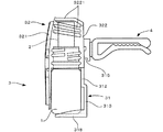
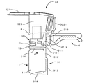
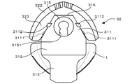
以下、本発明に係る薬剤揮散器の一実施形態について図面を参照しつつ説明する。なお、以下では、説明の便宜のため、図2の左側を正面側または前側、右側を背面側または後側と称する。また、図3の上下方向を幅方向と称する。そして、他の図面についてもこの方向にしたがって、説明を行う。但し、これらの方向は、本発明を限定するものではない。 Hereinafter, one embodiment of a chemical volatilizer according to the present invention will be described with reference to the drawings. In the following, for convenience of explanation, the left side of FIG. 2 is referred to as the front side or the front side, and the right side is referred to as the back side or the rear side. Further, the vertical direction in FIG. 3 is referred to as a width direction. The other drawings will be described according to this direction. However, these directions do not limit the present invention.
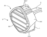
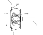
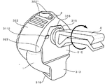
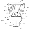
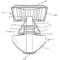
図1は本実施形態に係る薬剤揮散器の斜視図、図2は図1の側面図、図3は図1の平面図、図4は薬剤揮散器を後方から見た斜視図である。図1〜図4に示すように、本実施形態に係る薬剤揮散器は、液状の薬剤が収容された薬剤容器1と、この薬剤容器1に差し込まれ、薬剤を含浸する吸液芯2と、薬剤容器1を支持する支持体3と、この支持体3を取付対象物に取り付けるための固定部4と、を有している。以下、これら各部材について詳細に説明する。
1 is a perspective view of a drug volatilizer according to the present embodiment, FIG. 2 is a side view of FIG. 1, FIG. 3 is a plan view of FIG. 1, and FIG. As shown in FIG. 1 to FIG. 4, the drug volatilizer according to the present embodiment includes a
<1.薬剤容器>
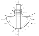
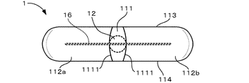
図5は薬剤容器の正面図、図6は薬剤容器の底面図、図7は図5のA−A線断面図である。図5〜図7に示すように、本実施形態に係る薬剤容器1は、正面視逆三角形状の本体部11と、この本体部11の上端に連結された首部12と、を備えており、これらは一体的に形成されている。本体部11は、底面111、一対の側面112a,112b、前面113、背面114、及び上面115によって囲まれた内部空間を有しており、この内部空間に薬剤が収容される。底面111は、平面視矩形状に形成され、左右の縁部(周縁)は凸状に湾曲している。また、一対の側面112は、底面111の左右の縁部1111からそれぞれ斜め上方に向かって互いに離れるように延びている。前面113及び背面114は、底面111の前側及び後側の縁部からそれぞれ上方に向かって延びている。上面115は、一対の側面112、前面113、及び背面114の上端縁をつなぐように概ね水平に延びる矩形状に形成されている。そして、上面115の中央には、上述した首部12が連結されている。
<1. Drug container>
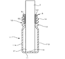
5 is a front view of the drug container, FIG. 6 is a bottom view of the drug container, and FIG. 7 is a cross-sectional view taken along line AA of FIG. As shown in FIGS. 5-7, the chemical |
首部12は、上端に開口121を有する円筒状に形成されており、底面111の直上に配置されている。首部12の外周面において、上面115に近接する位置には、環状の突部13が形成されており、この突部13と上面115との間の隙間に、後述する保持部が配置される。また、首部12の外周面において、突部13よりも上方には、螺旋状の雄ねじ14が形成されている。この雄ねじ14は,図示を省略するキャップの雌ねじが螺合するようになっている。すなわち、首部12には、キャップが取り付けられ、使用時に取り外すようになっている。
The
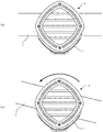
本体部11の内壁面は、次のように構成されている。まず、底面111及び一対の側面112には、左右方向に延びる突条16が形成されている。この突条16は、底面111及び側面112の前後方向の中心付近を、一方の側面112aの上下方向の中心付近から、底面111を経て、他方の側面112bの上下方向の中心付近まで延びている。また、この突条16には、溝が形成されており、突条16に沿って延びている。
The inner wall surface of the
また、上面115の内壁面にも一対の突条17a,17bが形成されている。各突条17a,17bは、上面115の前後方向の中心付近を通過しており、上面115の左右の端部付近から首部12に向かって延び、首部12の内壁面を開口121の縁部まで上方に向かって延びている。これらの突条17a,17bにも、溝が形成されており、突条17a,17bに沿って延びている。
A pair of
以上のような薬剤容器1は、種々の材料により形成することができるが、樹脂材料により形成することができる。この場合、例えば、前後方向の中心付近で分割した状態(形成される突条16,17a,17bも前後方向の中心付近で分割されている)に形成したものを張り合わせたり、また、ブロー法(例えば、インジェクションブロー法、ダイレクトブロー法)により成形した後、底面111及び側面112の内壁面を削ったり、突条を貼り付けたりして薬剤容器1を形成することができる。ブロー法のうち、特にダイレクトブロー法により薬剤容器1を成形する場合には、筒状のパリソンを用い、2つの成形型でパリソンの上部を挾み、雄ねじ14及び突部13が形成された首部12のみを先に成形し、続いて、成形された首部12よりも下方の部分を2つの成形型で挾み、パリソンに空気を注入しつつ本体部11を成形する。首部12よりも下方の部分を2つの成形型で挟む際、互いの成形型が接する箇所の樹脂材料が盛り上がるようにすることで、突条16,17a,17bを成形することができる。
The
また、薬剤容器1は、内部の薬剤が視認できるように透明または半透明の材料で形成することが好ましい。薬剤容器1に収容される液状の薬剤としては、用途に応じて、公知の芳香液、消臭液、アロマオイルなど、種々のものを用いることができる。
Moreover, it is preferable to form the
<2.吸液芯と薬剤容器への取付構造>
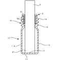
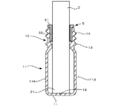
次に、吸液芯2及び薬剤容器1への取付構造について説明する。まず、図7に示すように、薬剤容器1には、吸液芯2の取付部材5が取り付けられており、この取付部材5を介して、吸液芯2が薬剤容器1に取り付けられている。取付部材5は、薬剤容器1の首部12の内壁面に圧入される円筒状の取付本体51と、この取付本体51の上縁から径方向外方に延びるフランジ部52とを備えている。そして、取付本体51の内部には、吸液芯2が挿入される。また、フランジ部52は、首部12の開口周縁を上方から覆うように配置される。
<2. Mounting structure for liquid core and drug container>
Next, the attachment structure to the
また、取付本体51の内壁面には、上下方向に沿って延びる溝(図示省略)が形成されており、吸液芯2が挿入されたときに、この溝によって吸液芯2と取付本体51との間に隙間が形成される。この隙間は、薬剤容器1の内部空間と外部とを連通する。これにより、例えば、高温の環境で薬剤容器1を用い、薬剤容器1の内圧が上昇したとき、薬剤容器1内の空気が隙間を通じて外部に排出されるようになっている。一方、このような隙間が設けられていないと、内圧が上昇したとき、吸液芯2を通じて薬剤が過剰に押し出されるおそれがある。
Further, a groove (not shown) extending in the vertical direction is formed on the inner wall surface of the mounting
続いて、吸液芯2について説明する。吸液芯2は、円柱状に形成されており、上述したように、取付本体51の内壁面に密着した状態で、取付本体51に挿入される。そして、吸液芯2の長さは、次のように設定されている。すなわち、吸液芯2の下端部が薬剤容器1の底面111に当接したとき、吸液芯2の上端部は、首部12から突出した状態となるように設定されている。このとき、吸液芯2の下端部21の下面が底面111に接しつつ、下端部21の周縁が底面の左右の縁部1111にも接するようになっている。
Next, the liquid
吸液芯2を構成する材料は、薬剤を吸い上げ、首部12から突出している部分から薬剤を外部に揮散させることができるような材料であれば、特には限定されない。例えば、紙、布など種々の材料を用いることができる。
The material which comprises the
<3.支持体>
続いて、支持体3について、図8〜図12を参照しつつ説明する。図8は第2のポジションにある支持体の斜視図、図9は図8の正面図、図10は第2のポジションにおいて薬剤容器が装着された支持体の側面図、図11は図10の正面図、図12は図10の背面図である。但し、図12では説明の便宜上、固定部を取り外した状態を示している。
<3. Support>
Next, the
図8〜図12に示すように、支持体3は、薬剤容器1を保持する支持本体(上下支持部)31と、この支持本体31に取り付けられ、薬剤容器1を覆うカバー32と、を備えており、カバー32は薬剤容器1を覆う第1のポジション(図1〜図4)と薬剤容器1を取り外し可能な第2のポジション(図8〜図12)とを取り得る。以下では、説明の便宜のため、支持体3が第1のポジションを取りうる場合と第2のポジションを取りうる場合との両方を参照しつつ、支持体3について説明する。まず、支持本体31について説明する。
As shown in FIGS. 8 to 12, the
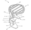
支持本体31は、上方から下方に向かって配置された上端部311、中間部(第1支持部)312、及び下端部(第2支持部)313が一体的に形成された板状の部材であり、上端部311と中間部312との間には板状の保持部314が連結されている。上端部311は、正面視台形状の板状に形成されており、その中央には背面側に突出する環状の取付部315が形成されている。図12に示すように、この取付部315は、下側に切欠き3151が形成されており、後述する固定部4の軸部が切欠き3151から取付部315の穴に取り付けられる。また、上端部311の左右の辺には、それぞれ、前面側に第1係止部3111が形成され、背面側に第2係止部3112が形成されている。また、第1係止部3111は、中間部312側に配置され、第2係止部3112は、第1係止部3111よりも上方に配置されている。そして、これら第1係止部3111及び第2係止部3112によって、後述するカバー32の一部が挟まれる。また、上端部311の上辺にはヒンジ316が形成され、このヒンジ316を介して、カバー32が揺動自在に取り付けられている。
The
中間部312は、正面視矩形状の板状に形成されており、上端部311の下端に連結されている。そして、上端部311と中間部312との間には、上述したように、薬剤容器1の首部12を保持する保持部314が連結されている。保持部314は、板状に形成された一対の保持片3141a,3141bを備えており、これら保持片3141は前方に向かって延びている。そして、これら保持片3141は、左右方向の中央に隙間を空けて配置されており、この隙間に薬剤容器1の首部12が保持される。より詳細に説明すると、両保持片3141a,3141bの隙間は、首部12の外周面に沿うように平面視円形状に形成されているが、両保持片3141a,3141bの前端部間の隙間は、首部12の直径よりも狭くなっている。これにより、首部12の抜け止めを形成している。なお、保持部314の前後方向の長さは、薬剤容器1の前後方向の幅の半分よりも長いことが好ましい。
The
また、中間部312は、薬剤容器1の背面114に当接するように構成されており、薬剤容器1の本体部11の上端から、本体部11の上下方向の中間部付近まで延びている。より詳細には、図10に示すように、中間部312は、薬剤容器1の重心Gと対応する上下方向の位置を越えて、下方に延びている。
The
下端部313は、中間部312の背面の下端から下方に延びる正面視矩形状の板状に形成されている。これにより、下端部313は、中間部312よりも後方に配置され、中間部312に当接している薬剤容器1の背面114との間に隙間が形成される。また、下端部313の左右方向の幅は、中間部312よりも狭くなっており、保持部314に薬剤容器1が保持されたときには、薬剤容器1に遮られて正面からは下端部313が見えないようになっている。そして、下端部313の前面の中央には上下方向に延びる棒状の突部317が形成されており、この突部317の前面は中間部312の前面よりも後側にある。また、下端部313の下端縁には、平面視矩形状の板状の底面支持部318が連結されている。この底面支持部318は、保持部314と概ね同じ長さで前方に突出しており、薬剤容器1の底面111に当接するように構成されている。
The
続いて、カバー32について説明する。カバー32は、ヒンジ316を介して支持本体31に連結されることにより、上記のように薬剤容器1を覆う使用時の第1ポジションと、薬剤容器1を取り付けたり、あるいは取り外すときの第2ポジションを取り得る。
Next, the
カバー32は、支持本体31の前側に配置される前壁部(第1壁面)321と、前壁部321の上端縁に連結され,前後方向に延びる上壁部(第2壁面)322と、上壁部322の後端縁から上下方向に延び、支持本体31の上端部311の周囲を囲む背壁部323と、を備えている。
The
前壁部321は、正面視菱形状に形成されており、前面には装飾が施されている。前壁部321は、支持本体31に保持される薬剤容器1がほぼ隠れるような大きさに、形成されている。上壁部322は、前壁部321の上端部に沿うように正面視へ字状に形成されており、薬剤容器1に差し込まれた吸液芯2を上方から覆うように配置される。そして、上壁部322の上端付近には、開口が形成されるとともに、この開口の一部を塞ぐように前後方向に延びる複数の棒状部材3221が平行に配置されている。棒状部材3221の配置されている間隔は、吸液芯2の直径よりも小さくなっている。これにより、上壁部322からは、吸液芯2から揮発する薬剤は通過するが、吸液芯2が抜け出さないようになっている。
The
背壁部323は、上壁部322の後端縁に沿うように正面視へ字状に形成されており、上述したように、支持本体31の上端部311の周囲を囲むように板状に形成されている。まず、支持本体31の上端部311の上辺が、ヒンジ316を介して背壁部323に連結されている。また、背壁部323の両側の内周縁は、支持本体31の上端部311に形成された第1係止部3111及び第2係止部3112によって挟まれる。これにより、背壁部323が支持本体31に固定され、カバー32が第1ポジションに保持される。
The
続いて、カバー32が第2ポジションにあるときについて、説明する。第1ポジションでは、図1〜図4に示すように、カバー32が薬剤容器1を覆うため、前壁部321は支持本体31と概ね平行になるように上下方向に延びるように配置される。この状態から、前壁部321を上方に向けて傾斜させると、第1係止部3111及び第2係止部3112と背壁部323との係止状態が解除され、カバー32がヒンジ316を中心として揺動可能となる。そして、例えば、図10に示すように、カバー32は、前壁部321が支持本体31の上方で水平に延びる状態まで揺動し、第2ポジションとなる。この状態で、薬剤容器1は外部に露出するため、取り外し可能となる。
Next, the case where the
<4.固定部>
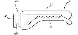
次に、固定部4について、図13も参照しつつ説明する。図13は固定部の側面図である。固定部4は、支持本体31における上端部311の取付部315から背面側に延びるように形成されている。より詳細には、取付部315に回転自在に連結される連結部43と、この連結部43から後方に延びる板状の第1固定片41と、この第1固定片41の下側に平行に延びる板状の第2固定片42と、を備えており、これらは一体的に形成されている。連結部43は、小径の軸部431と、その前側に取り付けられ、軸部431よりも径の大きい円形の抜け止め部432とを備えており、軸部431が、取付部315の穴に切欠き3151を介して取り付けられる。取付部315の内径は、軸部431とほぼ同じであるが、抜け止め部432よりは小さいため、連結部43は、取付部315において前後方向に延びる軸周りに回転自在に取り付けられる。また、切欠き3151の幅は、軸部431の径よりも小さいため、切欠き3151は軸部431の抜け止めになる。このとき、連結部43は、ほぼ抵抗なく取付部315に対して回転するようになっており、これによって、例えば、支持体3が振動を受けた場合、支持体3は固定部4に対して回転するようになっている。
<4. Fixed part>
Next, the fixing
第1固定片41及び第2固定片42は連結部43に対して、弾性変形可能となっており、これにより、両固定片41,42は、互いに近接離間するように変形可能である。初期状態では、両固定片41,42の後端部は接しており、これを弾性力に抗して押し広げることで、両固定片41,42の間には、取付対象物を弾性的に挟むことができるようになっている。
The first
<5.薬剤揮散器の使用方法>
次に、上記のように構成された薬剤揮散器の使用方法について説明する。まず、薬剤容器1のキャップを取り外し、吸液芯2を露出させる。続いて、支持体3のカバー32を開いて第2ポジションとし、保持部314を露出させる。これに続いて、保持部314の両保持片3141a,3141bの間に、薬剤容器1の首部12を挿入する。具体的には、首部12の突部13と本体部11の上面115との隙間に、両保持片3141a,3141bの内縁が係合するようにする。この状態で、両保持片3141a,3141bの前端側の隙間は、首部12の径よりも狭いので、これが抜け止めになって、首部12が保持部314から離脱するのが防止される。こうして、首部12が保持部314に装着されると、薬剤容器1の本体部11の背面114は、支持本体31の中間部312に当接するとともに、本体部11の底面111が底面支持部318に当接する。
<5. Usage of chemical volatilizer>
Next, the usage method of the chemical volatilizer comprised as mentioned above is demonstrated. First, the cap of the
このように、保持部314は首部12の突部13と本体部11の上面115との隙間に係合するが、これが上下方向のいずれかにずれると、本体部11の底面111が底面支持部318に当接せず、例えば、本体部11が底面支持部318に当たって、薬剤容器1が支持体3に装着できないようになっている。そのため、底面支持部318は、薬剤容器1を正しい位置に装着するためのガイドとしても機能する。
As described above, the holding
こうして、薬剤容器1が装着されると、カバー32を第1ポジションに戻す。これにより、薬剤容器は1、カバー32の前壁部321により前方への移動が規制され、支持本体31から離脱するのが防止される。また、カバー32の上壁部322が吸液芯2を上方から覆うため、吸液芯2が薬剤容器1から離脱するのを防止することができる。
Thus, when the
続いて、固定部4を取付対象部に取り付ける。すなわち、固定部4の両固定片41、42で取付対象物を挟むようにする。こうして、薬剤揮散器の取り付けが完了する。なお、取付対象物は特には限定されないが、例えば、自動車のエアコンやデフロスターの排気口など、振動を伴うものとすることができる。但し、振動が生じるような取付対象物は、上記のような排気口以外でもよく、特には限定されない。
Subsequently, the fixing
その後、薬剤容器1内の薬剤は、吸液芯2に吸い上げられ、吸液芯2を伝って、薬剤容器1の外部へと揮散する。これにより、芳香効果等を得ることができる。そして、本実施形態に係る薬剤揮散器では、以下の理由から、薬剤容器1内の薬剤の量が少なくなっても、最後まで薬剤を使い切ることができる。まず、吸液芯2の下端部21は、薬剤容器1の底面111に接しており、さらに、吸液芯2の下端部21の少なくとも一部が、底面111の縁部1111に接している。そのため、側面112から流れ落ち、底面111に達した薬剤のうち、表面張力によって底面111の縁部付近に残留する薬剤も吸引することができる。また、本体部11の側面112から底面111に亘って、溝を有する突条16が形成されているため、薬剤はこの突条16を伝うことで、底面111まで流れ落ちやすくなる。その結果、吸液芯2によって流れ落ちた薬剤を吸い上げやすくなる。さらに、例えば、薬剤容器1を逆さに向けると、薬剤は本体部11の上面115に溜まるが、この薬剤は、上面115の突条17a,17bを伝って、首部12へと流れ、吸液芯2に吸引される。
Thereafter, the drug in the
このように、吸液芯2が底面111の縁部に接していること、及び突条16,17が形成されていることから、本実施形態の薬剤容器1では、薬剤が容器内に残留するのを防止することができ、薬剤を最後まで使い切ることができる。
Thus, since the
<6.特徴>
以上のように、本実施形態によれば、次の特徴を有している。
<6. Features>
As described above, this embodiment has the following features.
<6−1>
薬剤を収容する薬剤容器1の首部12が、支持体3の保持部314により左右から挟まれるように保持されているため、薬剤容器1が横方向からの振動を受けても、薬剤容器1が支持体から離脱するのを防止することができる。その結果、薬剤容器1から薬剤がこぼれるのを防止することができる。
<6-1>
Since the
<6−2>
首部12の外周面に、突部13が形成されており、突部13と本体部11の上面115との隙間に、314保持部が係合するため、薬剤容器1の上下方向の移動が拘束される。そのため、薬剤容器1が上下方向の振動を受けても、支持体3から離脱するのを防止することができる。
<6-2>
A
<6−3>
薬剤容器1の本体部11は、上下方向において、保持部314と底面支持部318との間に挟まれた状態となっているため、一旦、薬剤容器1が支持体3に装着されると、斜め上方あるいは斜め下方には移動できないようになっており、薬剤容器1の離脱を防止することができる。
<6-3>
Since the
<6−4>
薬剤容器1の本体部11の外周面全体が支持本体31に支持されているのでなく、薬剤容器1は、支持本体31のうち、中間部312と当接し、下端部313とは隙間を空けている。そのため、薬剤容器1が振動を受けても、その振動の少なくとも一部を下端部313との隙間で吸収することができる。その結果、振動を受けたとき、薬剤容器1が支持本体31からの衝撃で破損するのを防止することができる。また、下端部313には棒状の突部317が形成されているため、薬剤容器1が隙間側へ移動したときには、この突部317がクッションとなって接触する。
<6-4>
The entire outer peripheral surface of the
さらに、中間部312は、薬剤容器1の重心Gと対応する上下方向の位置において、薬剤容器1の本体部11の外周面と当接しているため、振動を受けたとき(特に薬剤容器内の薬剤の残量が少なくなったとき)でも、薬剤容器1が支持本体31に対して大きく揺れるのを防止することができる。
Further, since the
<6−5>
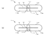
支持体3には、固定部4が回転自在に取り付けられているため、次のような効果がある。すなわち、支持体3が振動を受けた場合、支持体3は固定部4に対して回転するようになっている。したがって、例えば、取付対象物7が図14(a)に示す水平な状態から、図14(b)に示す傾いた状態になったとしても、支持体3の重心が、支持体3と固定部4との連結部分の鉛直下方に位置するように、支持体3は回転する。そのため、薬剤容器1は、開口121が上方を向いた状態に維持されるため、薬剤がこぼれるのを防止することができる。
<6-5>
Since the fixing
<7.変形例>
以上、本発明の一実施形態について説明したが、本発明はこれに限定されるものではなく、その趣旨を逸脱しない限りにおいて種々の変更が可能である。なお、以下の変形例は、適宜組合わせ可能である。
<7. Modification>
As mentioned above, although one Embodiment of this invention was described, this invention is not limited to this, A various change is possible unless it deviates from the meaning. The following modifications can be combined as appropriate.
<7−1>
上記実施形態では、首部12の突部13と本体部11の上面115との間に保持部314を係合させているが、これに限定されるものでない。すなわち、首部12に設けられた雄ねじ14を利用して保持部314を係合させることもできる。また、首部12の突部13は、首部12の全周に亘って設ける必要はなく、一部でもよい。さらに、突部13を首部12の軸方向に複数設け、隣接する突部13の間に保持部314を係合させてもよい。
<7-1>
In the above embodiment, the holding
保持部314の形態は、特には限定されず、首部の径方向外方から首部を挟むように保持するものであれば、特には限定されない。また、首部に限られず、本体部を径方向外方から挟むように保持することもできる。
The form of the holding
<7−2>
支持体3の形態も、特には限定されず、少なくとも保持部314が設けられていればよい。したがって、カバーも必要に応じて設けられればよい。
<7-2>
The form of the
<7−3>
固定部4の形態も特には限定されず、取付対象物に固定できればよい。また、固定部を設けず、両面テープなどで、支持体3を取付対象物に直接固定することもできる。
<7-3>
The form of the fixing
<7−4>
薬剤容器1の形態も特には限定されず、少なくとも上部に開口121を有し、この開口121から薬剤に含浸されるように吸液芯2が挿入可能であればよい。したがって、形状、材料などは特には限定されない。
<7-4>
The form of the
<7−5>
薬剤容器1に形成された突条16、17a,17bは、薬剤を伝わせるために形成されたものであるが、これに限定されない。例えば、上記各突条16、17a,17bには溝が形成されているが、溝は必ずしもなくてもよく、図15に示すように、突条17だけでもよい。また、上記実施形態では、突条を薬剤容器1の底面111から側面112に亘って(16)と、上面115から首部12に亘って(17a,17b)形成しているが、少なくとも一方があればよい。また、複数の突条を設けることもできる。さらに、突条の代わりに、図16に示すように、薬剤容器1の内壁面に溝18を形成することもできる。
<7-5>
The
<7−6>
上記実施形態においては、図6に示すように、吸液芯2の下端部21は、薬剤容器の底面111の左右の縁部1111に接しているが、少なくとも一部が接していればよい。例えば、図17(a)に示すように、吸液芯2の下端部21の径が小さく、一方の縁部1111にのみ接していてもよいし、図17(b)に示すように、底面111のいずれかの縁部(この例では背面側)に接していてもよい。また、底面111の形状も特には限定されず、吸液芯2の下端部21の一部が縁部のいずれかに接するような形状であればよい。但し、このような構成は、必ずしも必要ではないが、設けられていることが好ましい。
<7-6>
In the above embodiment, as shown in FIG. 6, the
1 :薬剤容器
11 :本体部
111 :底面
112 :側面(外周面)
113 :前面(外周面)
114 :背面(外周面)
115 :上面(外周面)
12 :首部
121 :開口
13 :突部
2 :吸液芯
21 :下端部
3 :支持体
31 :支持本体(上下支持部)
312 :中間部(第1支持部)
313 :下端部(第2支持部)
314 :保持部
318 :底面支持部
32 :カバー
4 :固定部
G :重心
1: Drug container 11: Main body 111: Bottom surface 112: Side surface (outer peripheral surface)
113: Front surface (outer peripheral surface)
114: Back surface (outer peripheral surface)
115: Upper surface (outer peripheral surface)
12: Neck part 121: Opening 13: Projection part 2: Liquid absorption core 21: Lower end part 3: Support body 31: Support body (upper and lower support part)
312: Intermediate part (first support part)
313: Lower end portion (second support portion)
314: Holding portion 318: Bottom support portion 32: Cover 4: Fixing portion G: Center of gravity
Claims (8)
前記薬剤容器の開口に差し込まれる吸液芯と、
前記薬剤容器を支持するとともに、取付対象物に取り付けられる支持体と、
を備え、
前記支持体は、前記開口の軸線方向に対する径方向外方から、前記薬剤容器を挟むように保持する保持部を備えている、薬剤揮散器。 A drug container having an opening at the top and containing a liquid drug;
A liquid absorbent core to be inserted into the opening of the drug container;
Supporting the drug container, and a support attached to the attachment object;
With
The said support body is provided with the holding | maintenance part hold | maintained so that the said medicine container may be pinched | interposed from the radial direction outer side with respect to the axial direction of the said opening.
前記保持部は、前記首部を保持するように構成されている、請求項1に記載の薬剤揮散器。 The drug container includes a neck part in which the opening is formed, and a main body part having an outer shape larger than the neck part and connected to the neck part,
The drug volatilizer according to claim 1, wherein the holding part is configured to hold the neck part.
前記突部と前記本体部との間の隙間に、前記保持部が係合するように構成されている、請求項2に記載の薬剤揮散器。 A protrusion is formed on the outer peripheral surface of the neck,
The chemical volatilizer according to claim 2, wherein the holding unit is engaged with a gap between the protrusion and the main body.
前記保持部が設けられている側とは反対側から前記薬剤容器を覆う第1壁面と、
前記吸液芯が差し込まれた前記開口側を覆う第2壁面と、を備えたカバーをさらに備え、
前記第2壁面は、気体が通過可能に構成されている、請求項1から3のいずれかに記載の薬剤揮散器。 The support is
A first wall surface covering the drug container from the side opposite to the side where the holding unit is provided;
A second wall surface covering the opening side into which the liquid absorption core is inserted, and further comprising a cover,
The chemical volatilizer according to any one of claims 1 to 3, wherein the second wall surface is configured to allow gas to pass therethrough.
前記保持部は、前記首部を保持するように構成されており、
前記支持体は、
前記薬剤容器の重心と対応する上下方向の位置において、前記本体部の外周面と当接する第1支持部と、
前記第1支持部に連結され、当該第1支持部よりも下方において、前記本体部と隙間を空けて配置される第2支持部と、を備えている、請求項1から4のいずれかに記載の薬剤揮散器。 The drug container includes a neck part in which the opening is formed, and a main body part having an outer shape larger than the neck part and connected to the neck part,
The holding part is configured to hold the neck part,
The support is
A first support portion in contact with the outer peripheral surface of the main body portion at a vertical position corresponding to the center of gravity of the medicine container;
5. The apparatus according to claim 1, further comprising: a second support portion that is connected to the first support portion and is disposed below the first support portion and spaced from the main body portion. The chemical volatilizer as described.
前記保持部は、前記首部を保持するように構成されており、
前記支持体は、
上下方向に延び、前記保持部が前記首部に向けて延びるように連結されるとともに、少なくとも一部が前記本体部の外周面と当接する、上下支持部と、
前記上下支持部の下端部に連結され、前記保持部と同じ方向に、前記本体部の底面を支持するように延びる底面支持部と、を備えている、請求項1から4のいずれかに記載の薬剤揮散器。 The drug container includes a neck part in which the opening is formed, and a main body part having an outer shape larger than the neck part and connected to the neck part,
The holding part is configured to hold the neck part,
The support is
An upper and lower support portion that extends in the vertical direction and is connected so that the holding portion extends toward the neck portion, and at least a part of which is in contact with the outer peripheral surface of the main body portion;
5. A bottom support portion connected to a lower end portion of the upper and lower support portions and extending in the same direction as the holding portion so as to support a bottom surface of the main body portion. Chemical volatilizer.
前記吸液芯の下端部の少なくとも一部が、前記底面の周縁のいずれかに当接するように構成されている、請求項1から7のいずれかに記載の薬剤揮散器。 The drug container includes a bottom surface formed immediately below the opening, and an outer peripheral surface extending upward from a peripheral edge of the bottom surface,
The drug volatilizer according to any one of claims 1 to 7, wherein at least a part of a lower end portion of the liquid-absorbing core is configured to come into contact with any one of the peripheral edges of the bottom surface.
Priority Applications (1)
| Application Number | Priority Date | Filing Date | Title |
|---|---|---|---|
| JP2015001139A JP6609101B2 (en) | 2015-01-06 | 2015-01-06 | Chemical volatilizer |
Applications Claiming Priority (1)
| Application Number | Priority Date | Filing Date | Title |
|---|---|---|---|
| JP2015001139A JP6609101B2 (en) | 2015-01-06 | 2015-01-06 | Chemical volatilizer |
Publications (2)
| Publication Number | Publication Date |
|---|---|
| JP2016123765A true JP2016123765A (en) | 2016-07-11 |
| JP6609101B2 JP6609101B2 (en) | 2019-11-20 |
Family
ID=56358429
Family Applications (1)
| Application Number | Title | Priority Date | Filing Date |
|---|---|---|---|
| JP2015001139A Active JP6609101B2 (en) | 2015-01-06 | 2015-01-06 | Chemical volatilizer |
Country Status (1)
| Country | Link |
|---|---|
| JP (1) | JP6609101B2 (en) |
Cited By (1)
| Publication number | Priority date | Publication date | Assignee | Title |
|---|---|---|---|---|
| WO2025063792A1 (en) * | 2023-09-22 | 2025-03-27 | 채수인 | Air vent attachable type air freshener |
Citations (3)
| Publication number | Priority date | Publication date | Assignee | Title |
|---|---|---|---|---|
| JP2005058338A (en) * | 2003-08-08 | 2005-03-10 | Earth Chem Corp Ltd | Volatilization apparatus, outer container for volatilization apparatus, and storage container |
| JP2006523561A (en) * | 2003-04-16 | 2006-10-19 | ゾベレ エスパーニャ ソシエダッド アノニマ | Air freshener diffuser for vehicles |
| US7140553B2 (en) * | 2003-06-10 | 2006-11-28 | Zobele Holding Spa | Device for diffusing volatile substances, in particular deodorants for vehicle interiors |
-
2015
- 2015-01-06 JP JP2015001139A patent/JP6609101B2/en active Active
Patent Citations (3)
| Publication number | Priority date | Publication date | Assignee | Title |
|---|---|---|---|---|
| JP2006523561A (en) * | 2003-04-16 | 2006-10-19 | ゾベレ エスパーニャ ソシエダッド アノニマ | Air freshener diffuser for vehicles |
| US7140553B2 (en) * | 2003-06-10 | 2006-11-28 | Zobele Holding Spa | Device for diffusing volatile substances, in particular deodorants for vehicle interiors |
| JP2005058338A (en) * | 2003-08-08 | 2005-03-10 | Earth Chem Corp Ltd | Volatilization apparatus, outer container for volatilization apparatus, and storage container |
Cited By (1)
| Publication number | Priority date | Publication date | Assignee | Title |
|---|---|---|---|---|
| WO2025063792A1 (en) * | 2023-09-22 | 2025-03-27 | 채수인 | Air vent attachable type air freshener |
Also Published As
| Publication number | Publication date |
|---|---|
| JP6609101B2 (en) | 2019-11-20 |
Similar Documents
| Publication | Publication Date | Title |
|---|---|---|
| CN103826758B (en) | Liquid dispensing apparatus | |
| ES2367660T3 (en) | ELIMINATION AND COLLECTION DEVICES OF MEDICAL INSTRUMENTS. | |
| WO2007142851A3 (en) | Passive dispensing device | |
| WO2016178325A1 (en) | Container holder | |
| JP5471956B2 (en) | Humidification unit and humidifier equipped with the same | |
| JPWO2017183213A1 (en) | container | |
| JP6609101B2 (en) | Chemical volatilizer | |
| CN105593138A (en) | Inside plug and suction-type liquid container | |
| TWI734450B (en) | Atomization device | |
| JP6591750B2 (en) | Drug container and drug volatilizer equipped with the same | |
| JP6734021B2 (en) | Bag container | |
| JP2016123766A (en) | Chemical agent vaporizer | |
| JP6641142B2 (en) | Drug vaporizer | |
| JP2012115364A (en) | Volatilization device | |
| JP5904415B2 (en) | Liquid spray device | |
| JP6037750B2 (en) | Cup container lid | |
| JP2010089592A (en) | Cup holder | |
| JP6896407B2 (en) | Volatilizer | |
| JP6014447B2 (en) | Cup container lid | |
| JP5547970B2 (en) | Volatile agent diffuser | |
| JP2020039446A (en) | Fragrance equipment | |
| JP6916590B2 (en) | Drug volatilizer | |
| BRPI0513658B1 (en) | distributor, in particular dosing distributor | |
| JP6804950B2 (en) | Volatilizer | |
| US20110314956A1 (en) | Assembly and Welding Method for Coupling a Rotor to the Shaft of a Pedal Assembly |
Legal Events
| Date | Code | Title | Description |
|---|---|---|---|
| A621 | Written request for application examination |
Free format text: JAPANESE INTERMEDIATE CODE: A621 Effective date: 20171212 |
|
| A977 | Report on retrieval |
Free format text: JAPANESE INTERMEDIATE CODE: A971007 Effective date: 20180719 |
|
| A131 | Notification of reasons for refusal |
Free format text: JAPANESE INTERMEDIATE CODE: A131 Effective date: 20180807 |
|
| A601 | Written request for extension of time |
Free format text: JAPANESE INTERMEDIATE CODE: A601 Effective date: 20181009 |
|
| A521 | Request for written amendment filed |
Free format text: JAPANESE INTERMEDIATE CODE: A523 Effective date: 20181206 |
|
| A02 | Decision of refusal |
Free format text: JAPANESE INTERMEDIATE CODE: A02 Effective date: 20190423 |
|
| A521 | Request for written amendment filed |
Free format text: JAPANESE INTERMEDIATE CODE: A523 Effective date: 20190722 |
|
| A521 | Request for written amendment filed |
Free format text: JAPANESE INTERMEDIATE CODE: A523 Effective date: 20190823 |
|
| A911 | Transfer to examiner for re-examination before appeal (zenchi) |
Free format text: JAPANESE INTERMEDIATE CODE: A911 Effective date: 20190828 |
|
| TRDD | Decision of grant or rejection written | ||
| A01 | Written decision to grant a patent or to grant a registration (utility model) |
Free format text: JAPANESE INTERMEDIATE CODE: A01 Effective date: 20191008 |
|
| A61 | First payment of annual fees (during grant procedure) |
Free format text: JAPANESE INTERMEDIATE CODE: A61 Effective date: 20191025 |
|
| R150 | Certificate of patent or registration of utility model |
Ref document number: 6609101 Country of ref document: JP Free format text: JAPANESE INTERMEDIATE CODE: R150 |
|
| R250 | Receipt of annual fees |
Free format text: JAPANESE INTERMEDIATE CODE: R250 |
|
| R250 | Receipt of annual fees |
Free format text: JAPANESE INTERMEDIATE CODE: R250 |
|
| R250 | Receipt of annual fees |
Free format text: JAPANESE INTERMEDIATE CODE: R250 |
|
| R250 | Receipt of annual fees |
Free format text: JAPANESE INTERMEDIATE CODE: R250 |