JP6896407B2 - Volatilizer - Google Patents

Volatilizer Download PDF

Info

Publication number
JP6896407B2
JP6896407B2 JP2016233436A JP2016233436A JP6896407B2 JP 6896407 B2 JP6896407 B2 JP 6896407B2 JP 2016233436 A JP2016233436 A JP 2016233436A JP 2016233436 A JP2016233436 A JP 2016233436A JP 6896407 B2 JP6896407 B2 JP 6896407B2
Authority
JP
Japan
Prior art keywords
container
outer peripheral
peripheral surface
clip
volatilizer
Prior art date
Legal status (The legal status is an assumption and is not a legal conclusion. Google has not performed a legal analysis and makes no representation as to the accuracy of the status listed.)
Active
Application number
JP2016233436A
Other languages
Japanese (ja)
Other versions
JP2018090275A (en
Inventor
明神 弘恭
弘恭 明神
旻越 朱
旻越 朱
Current Assignee (The listed assignees may be inaccurate. Google has not performed a legal analysis and makes no representation or warranty as to the accuracy of the list.)
ST Corp
Original Assignee
ST Corp
Priority date (The priority date is an assumption and is not a legal conclusion. Google has not performed a legal analysis and makes no representation as to the accuracy of the date listed.)
Filing date
Publication date
Application filed by ST Corp filed Critical ST Corp
Priority to JP2016233436A priority Critical patent/JP6896407B2/en
Publication of JP2018090275A publication Critical patent/JP2018090275A/en
Application granted granted Critical
Publication of JP6896407B2 publication Critical patent/JP6896407B2/en
Active legal-status Critical Current
Anticipated expiration legal-status Critical

Links

Images

Description

本発明は、芳香剤等の薬液を収容し、この収容した薬液を揮散する揮散装置に関する。 The present invention relates to a volatilizer that stores a chemical solution such as an air freshener and volatilizes the contained chemical solution.

車内等の室内に芳香剤や消臭剤等を拡散する為に、揮散装置が用いられている。揮散装置は、芳香剤や消臭剤等の薬液を容器の内部に収容し、この収容した薬液を容器の内部に配置された吸液部材により吸い上げる。吸液部材により吸い上げられた薬液は、揮発し、容器の開口から周囲に出る。 A volatilizer is used to diffuse air fresheners, deodorants, etc. into the interior of a car or the like. The volatilizer stores a chemical solution such as an air freshener or a deodorant inside the container, and sucks up the stored chemical solution by a liquid absorbing member arranged inside the container. The chemical liquid sucked up by the liquid absorbing member volatilizes and exits from the opening of the container to the surroundings.

この種の揮散装置に用いられる薬液は揮発性を有しているので、周囲の温度の影響により容器内での薬液の気化した量が多くなると、容器内の圧力が高くなる。この為、揮散装置は、容器内の圧力上昇により容器が破損することを防止する為に、容器の内部及び外部を連通する通気用の通路を有している。 Since the chemical solution used in this type of volatilizer is volatile, the pressure inside the container increases as the amount of the chemical solution vaporized in the container increases due to the influence of the ambient temperature. Therefore, the volatilizer has a ventilation passage that communicates the inside and the outside of the container in order to prevent the container from being damaged due to an increase in pressure inside the container.

通気用の通路は、容器内に配置されてその内側に吸液部材を配置する中栓の外周面に形成された溝、及びこの溝を覆う容器の内面により構成する技術が知られている(例えば、特許文献1参照。)。 A technique is known in which a passage for ventilation is composed of a groove formed on the outer peripheral surface of an inner plug for arranging a liquid absorbing member inside the container and an inner surface of the container covering the groove (). For example, see Patent Document 1.).

特開2016−123766号公報Japanese Unexamined Patent Publication No. 2016-123766

上述の、通気用の通路を有する揮散装置には、以下の問題があった。即ち、揮散装置が転倒した場合、通気用の通路を通して容器内の薬液が外部へ漏れ出るという問題がある。特に車内においては、走行時の振動により揮散装置の転倒や落下が生じやすいという問題がある。揮散装置の転倒時に薬液が通路部を通して外部へ漏れ出ることを防止する方法として、出荷時の揮散装置内の薬液の量を、揮散装置の転倒時に薬液が通路を通して外部に漏れ出ることがない量に抑えることが考えられる。しかしながら、この方法では、揮散装置の出荷時の薬液の量が少なくなる傾向にあり、好ましくない。 The above-mentioned volatilizer having a passage for ventilation has the following problems. That is, when the volatilizer falls over, there is a problem that the chemical solution in the container leaks to the outside through the passage for ventilation. Especially in the vehicle, there is a problem that the volatilizer tends to fall or fall due to vibration during traveling. As a method of preventing the chemical solution from leaking to the outside through the passage when the volatilizer falls, the amount of the chemical solution in the volatilizer at the time of shipment is the amount at which the chemical solution does not leak to the outside through the passage when the volatilizer falls. It is conceivable to suppress it to. However, this method is not preferable because the amount of the chemical solution at the time of shipment of the volatilizer tends to be small.

そこで本発明は、転倒しても薬液が外部へ漏れ出ることを防止しつつ、薬液の量を多くすることができる揮散装置を提供することを目的とする。 Therefore, an object of the present invention is to provide a volatilizer capable of increasing the amount of the chemical solution while preventing the chemical solution from leaking to the outside even if the drug solution falls.

前記課題を解決し目的を達成するために、本発明の揮散装置は、次のように構成されている。本発明の一態様に係る揮散装置は、首部、前記首部に連続する肩部、及び、前記肩部に連続する本体部を有する有底筒状の容器、並びに、前記首部を着脱可能に内側に配置するリング部、及び、前記リング部に形成される連結部を有するリング部材を備え、外郭を規定する外郭体と、前記容器内に配置される吸液部材と、前記連結部に着脱可能に連結され、前記連結部に連結された状態で前記外郭体の外周面より外側に突出するクリップと、前記容器内に形成され、前記容器の内部及び外部を連通する通路部と、を備える。前記本体部の外周面は、平面部を有する。前記連結部の前記リング部の軸線側の面は、前記リング部が前記首部に取り付けられた状態で前記本体部の前記外周面の前記平面部に面接触して前記リング部材の前記首部回りの回転を防止する平面部を有する。前記通路部は、前記リング部が前記首部に取り付けられて前記連結部の前記平面が前記本体部の前記外周面の前記平面に面接触し、かつ、前記クリップが前記連結部に連結された状態で、前記容器の軸線を挟んで前記クリップの反対側の前記容器の軸方向のいずれかの位置に配置される。前記容器を軸方向に見たときに、前記外郭体の最外郭となる外周面の少なくとも前記クリップの反対側の部分は、前記本体部の軸線側を中心とする曲面に形成される。前記通路部は、前記クリップの幅方向の中心及び前記容器の軸線を通り、前記容器の軸線に平行な平面に配置される。前記曲面は、前記容器の軸線に直交する断面が円弧となる曲面であり、前記外郭体の前記外周面の180度以上の範囲に形成される。

In order to solve the above problems and achieve the object, the volatilizer of the present invention is configured as follows. The volatilizer according to one aspect of the present invention includes a neck portion, a shoulder portion continuous with the neck portion, a bottomed tubular container having a main body portion continuous with the shoulder portion, and the neck portion detachably inside. A ring portion to be arranged and a ring member having a connecting portion formed in the ring portion are provided, and an outer shell body defining the outer shell and a liquid absorbing member arranged in the container can be attached to and detached from the connecting portion. It is provided with a clip that is connected and projects outward from the outer peripheral surface of the outer shell in a state of being connected to the connecting portion, and a passage portion that is formed in the container and communicates with the inside and the outside of the container. The outer peripheral surface of the main body has a flat surface. The surface of the connecting portion on the axis side of the ring portion comes into surface contact with the flat surface portion of the outer peripheral surface of the main body portion in a state where the ring portion is attached to the neck portion, and is around the neck portion of the ring member. It has a flat surface portion that prevents rotation. The passage portion is in a state in which the ring portion is attached to the neck portion, the plane of the connecting portion is in surface contact with the plane of the outer peripheral surface of the main body portion, and the clip is connected to the connecting portion. The container is arranged at any position in the axial direction of the container on the opposite side of the clip so as to sandwich the axis of the container. When the container is viewed in the axial direction, at least a portion of the outer peripheral surface, which is the outermost outer shell of the outer shell, on the opposite side of the clip is formed on a curved surface centered on the axis side of the main body. The passage portion is arranged in a plane parallel to the axis of the container, passing through the center in the width direction of the clip and the axis of the container. The curved surface is a curved surface whose cross section orthogonal to the axis of the container is an arc, and is formed in a range of 180 degrees or more on the outer peripheral surface of the outer body.

本発明によれば、転倒しても薬液が外部へ漏れ出ることを防止しつつ、薬液の量を多くすることができる揮散装置を提供できる。 According to the present invention, it is possible to provide a volatilizer capable of increasing the amount of the chemical solution while preventing the chemical solution from leaking to the outside even if the drug solution falls.

本発明の一実施形態に係る揮散装置を示す斜視図。The perspective view which shows the volatilization apparatus which concerns on one Embodiment of this invention. 同揮散装置を示す断面図。The cross-sectional view which shows the volatilization apparatus. 同揮散装置の容器を示す平面図。The plan view which shows the container of the volatilizer. 同揮散装置の中栓を示す正面図。The front view which shows the inner plug of the volatilization device. 同中栓を示す平面図。The plan view which shows the inner plug. 同中栓を示す側面図。A side view showing the inner plug. 同揮散装置のリング部材を示す斜視図。The perspective view which shows the ring member of the volatilization apparatus. 同揮散装置のクリップを示す斜視図。The perspective view which shows the clip of the volatilization apparatus. 同クリップの端面を示す側面図。A side view showing the end face of the clip. 揮散装置10の要部を示す説明図。Explanatory drawing which shows the main part of the volatilization apparatus 10.

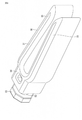
本発明の一実施形態に係る揮散装置10を、図1乃至図10を用いて説明する。図1は、揮散装置10を示す斜視図である。図2は、揮散装置10を示す断面図である。図3は、揮散装置10の容器20を示す平面図である。図4は、揮散装置10の中栓40を示す正面図である。図5は、中栓40を示す平面図である。図6は、中栓40を示す側面図である。図7は、揮散装置10のリング部材80を示す斜視図である。図8は、揮散装置10のクリップ90を示す斜視図である。図9は、クリップ90の端部を示す側面図である。図10は、揮散装置10の要部を示す説明図である。 The volatilizer 10 according to an embodiment of the present invention will be described with reference to FIGS. 1 to 10. FIG. 1 is a perspective view showing the volatilizer 10. FIG. 2 is a cross-sectional view showing the volatilizer 10. FIG. 3 is a plan view showing the container 20 of the volatilizer 10. FIG. 4 is a front view showing the inner plug 40 of the volatilizer 10. FIG. 5 is a plan view showing the inner plug 40. FIG. 6 is a side view showing the inner plug 40. FIG. 7 is a perspective view showing the ring member 80 of the volatilizer 10. FIG. 8 is a perspective view showing a clip 90 of the volatilizer 10. FIG. 9 is a side view showing an end portion of the clip 90. FIG. 10 is an explanatory diagram showing a main part of the volatilizer 10.

図1及び図2に示すように、揮散装置10は、揮散装置10の外郭すなわち外観を規定する外郭体であって、薬液を収容可能に形成された有底筒状の容器20、容器20に着脱可能に取り付けられるキャップ30等を有する外郭体5と、筒状に形成され、容器20内に配置される中栓40と、中栓40内に配置され、薬液を吸い上げることが可能に形成された吸液部材60と、中栓40に着脱可能に取り付けられる中キャップ70と、容器20に設けられたクリップ90と、を有している。本実施形態では、容器20の軸方向のうち容器20の開口が形成される側を上端として、揮散装置10の上下方向を設定する。 As shown in FIGS. 1 and 2, the volatilizer 10 is an outer shell of the volatilizer 10, that is, an outer shell that defines the appearance, and is formed in a bottomed tubular container 20 and a container 20 formed so as to be able to store a chemical solution. An outer shell 5 having a cap 30 or the like that can be detachably attached, an inner plug 40 that is formed in a tubular shape and is arranged in the container 20, and an inner plug 40 that is arranged in the inner plug 40 and is formed so that the chemical solution can be sucked up. It has a liquid absorbing member 60, an inner cap 70 that is detachably attached to the inner plug 40, and a clip 90 provided on the container 20. In the present embodiment, the vertical direction of the volatilizer 10 is set with the side in which the opening of the container 20 is formed as the upper end in the axial direction of the container 20.

外郭体5は、上述のように、揮散装置10の外観すなわち外郭を規定する。本実施形態では、外郭体5は、一例として、容器20、キャップ30、及び後述するリング部材80を有している。容器20は、外周面に雄ねじが形成された筒状の首部21、首部21の下端に連続して形成され、なだらかに拡径する肩部23、肩部23の下端に連続して形成された本体部24、及び首部21の外周面に形成されたフランジ22を有している。 As described above, the outer shell 5 defines the appearance of the volatilizer 10, that is, the outer shell. In the present embodiment, the outer shell 5 has, as an example, a container 20, a cap 30, and a ring member 80 described later. The container 20 was continuously formed at the tubular neck portion 21 having male threads formed on the outer peripheral surface and the lower end of the neck portion 21, and was continuously formed at the shoulder portion 23 and the lower end of the shoulder portion 23 having a gently expanding diameter. It has a flange 22 formed on the outer peripheral surface of the main body portion 24 and the neck portion 21.

図3に示すように、本体部24の外周面25は、本体部24の軸方向に平行な面に形成されている。本体部24の外周面25は、容器20をその軸方向に見たときに、容器20の外周面のうち最外郭となる外周面である。最外郭の外周面は、容器20のように複数の外径を有する筒状の径方向に最も外側の外周面である。なお、本実施形態では、図2に示すように、本体部24の外周面25がキャップ30の外周面よりも揮散装置10の径方向に外側に位置する。換言すると、揮散装置10を容器20の軸方向に見たときに、本体部24の外周面25が、キャップ30の外周面よりも外側に位置する。本実施形態では、本体部24の外周面25が、揮散装置10の外郭体5の最外郭となる外周面となる。外郭体5の最外郭となる外周面とは、後述するように、揮散装置10が転倒したときに、揮散装置10が載置された平面1に接触する外周面である。 As shown in FIG. 3, the outer peripheral surface 25 of the main body 24 is formed on a surface parallel to the axial direction of the main body 24. The outer peripheral surface 25 of the main body 24 is the outermost outer peripheral surface of the outer peripheral surface of the container 20 when the container 20 is viewed in the axial direction. The outermost outer peripheral surface is the outermost outer peripheral surface in the radial direction of a cylinder having a plurality of outer diameters like the container 20. In the present embodiment, as shown in FIG. 2, the outer peripheral surface 25 of the main body 24 is located outside the outer peripheral surface of the cap 30 in the radial direction of the volatilizer 10. In other words, when the volatilizer 10 is viewed in the axial direction of the container 20, the outer peripheral surface 25 of the main body 24 is located outside the outer peripheral surface of the cap 30. In the present embodiment, the outer peripheral surface 25 of the main body 24 is the outer peripheral surface which is the outermost outer shell of the outer shell body 5 of the volatilizer 10. As will be described later, the outermost outer peripheral surface of the outer shell 5 is an outer peripheral surface that comes into contact with the flat surface 1 on which the volatilizer 10 is placed when the volatilizer 10 falls.

外周面25は、円弧状に形成された第1の曲面部26、及び第1の平面部27を有している。第1の曲面部26は、首部21の軸線C1の延長線を中心とする円弧状の曲面に形成されている。すなわち、第1の曲面部26は、首部21の軸線の延長線に直交する断面が、この延長線を中心とする円弧に形成されている。なお、本実施形態では、首部21の軸線C1及び軸線Cの延長線を含む線を、第1の基準線L1とする。第1の曲面部26は、第1の基準線L1を中心として、180度以上の範囲に形成されている。本実施形態では、第1の曲面部26は、例えば、第1の基準線L1回りに300度の範囲に形成されている。 The outer peripheral surface 25 has a first curved surface portion 26 and a first flat surface portion 27 formed in an arc shape. The first curved surface portion 26 is formed on an arcuate curved surface centered on an extension line of the axis C1 of the neck portion 21. That is, the first curved surface portion 26 has a cross section orthogonal to the extension line of the axis of the neck portion 21 formed in an arc centered on the extension line. In the present embodiment, the line including the axis C1 of the neck portion 21 and the extension line of the axis C is referred to as the first reference line L1. The first curved surface portion 26 is formed in a range of 180 degrees or more with the first reference line L1 as the center. In the present embodiment, the first curved surface portion 26 is formed in a range of 300 degrees around the first reference line L1, for example.

第1の平面部27は、第1の基準線L1に平行な平面に形成されている。図2に示すように、本体部24の底壁部28の底面29aは、第1の基準線L1に直交する平面に形成されている。 The first plane portion 27 is formed on a plane parallel to the first reference line L1. As shown in FIG. 2, the bottom surface 29a of the bottom wall portion 28 of the main body portion 24 is formed in a plane orthogonal to the first reference line L1.

このように構成された本体部24は、その外周面25の断面が円であると仮定したときの軸線、すなわち第1の曲面部26の曲率中心が、第1の基準線L1に配置される。換言すると、同軸となる。 In the main body portion 24 configured in this way, the axis line when the cross section of the outer peripheral surface 25 is assumed to be a circle, that is, the center of curvature of the first curved surface portion 26 is arranged on the first reference line L1. .. In other words, it is coaxial.

フランジ22の外周面22aは、図3に示すように、第2の曲面部22b、及び第2の平面部22cを有している。第2の曲面部22bは、首部21の軸線C1を中心とする、断面が円弧となる曲面に形成されている。第2の曲面部22bの径は、第1の曲面部26の径よりも小さい。 As shown in FIG. 3, the outer peripheral surface 22a of the flange 22 has a second curved surface portion 22b and a second flat surface portion 22c. The second curved surface portion 22b is formed on a curved surface having an arcuate cross section centered on the axis C1 of the neck portion 21. The diameter of the second curved surface portion 22b is smaller than the diameter of the first curved surface portion 26.

第2の曲面部22bは、図3に示すように首部21の軸方向に見たときに、径方向に第1の曲面部26に対向する範囲に形成されている。第2の平面部22cは、首部21の軸線C1に平行な平面に形成されている。第2の平面部22cは、図3に示すように首部21の軸方向に見たとき、径方向に第1の平面部27に対向する範囲に形成されている。 As shown in FIG. 3, the second curved surface portion 22b is formed in a range facing the first curved surface portion 26 in the radial direction when viewed in the axial direction of the neck portion 21. The second plane portion 22c is formed on a plane parallel to the axis C1 of the neck portion 21. As shown in FIG. 3, the second flat surface portion 22c is formed in a range facing the first flat surface portion 27 in the radial direction when viewed in the axial direction of the neck portion 21.

キャップ30は、図1及び図2に示すように、有天筒状に形成されている。キャップ30は、具体的には、周壁部31及び上壁部32を有している。周壁部31の内周面33の開口端から軸方向の中途部までの範囲には、首部21に螺合可能な雌ねじが形成されている。周壁部31の外周面には、軸方向に延びる複数の溝部34が形成されている。複数の溝部34は、周方向に離間して配置されている。周壁部31の一部と、上壁部32の一部とには、複数の揮散口35が形成されている。複数の揮散口35は、周壁部31の一部及び上壁部32の一部を貫通している。 As shown in FIGS. 1 and 2, the cap 30 is formed in a heavenly cylinder shape. Specifically, the cap 30 has a peripheral wall portion 31 and an upper wall portion 32. A female screw that can be screwed into the neck portion 21 is formed in the range from the open end of the inner peripheral surface 33 of the peripheral wall portion 31 to the middle portion in the axial direction. A plurality of groove portions 34 extending in the axial direction are formed on the outer peripheral surface of the peripheral wall portion 31. The plurality of groove portions 34 are arranged apart from each other in the circumferential direction. A plurality of volatilization ports 35 are formed in a part of the peripheral wall portion 31 and a part of the upper wall portion 32. The plurality of volatilization ports 35 penetrate a part of the peripheral wall portion 31 and a part of the upper wall portion 32.

図2及び図4に示すように、中栓40は、内側に吸液部材60を配置可能な筒状に形成されている。中栓40は、その軸線C2が第1の基準線L1と同軸に配置される。中栓40は、具体的には、容器20の開口内に固定可能に形成された大径部41、及び大径部41に連続して形成された小径部42を有している。 As shown in FIGS. 2 and 4, the inner plug 40 is formed in a tubular shape in which the liquid absorbing member 60 can be arranged. The axis C2 of the inner plug 40 is arranged coaxially with the first reference line L1. Specifically, the inner plug 40 has a large-diameter portion 41 formed so as to be fixed in the opening of the container 20, and a small-diameter portion 42 continuously formed in the large-diameter portion 41.

大径部41は、首部21内に首部21と同軸に配置され、周方向に固定可能に形成されている。大径部41は、具体的には、首部21の内径よりも若干小さい径を有する有底筒状に形成されている。大径部41は、その開口縁部に、首部21の開口縁に軸方向に接触するフランジ43が形成されている。大径部41は、その長さが、首部21の軸方向の長さよりも短い。大径部41は、中栓40が容器20に取り付けられた状態、すなわち、フランジ43が首部21の上端開口に接触した状態で、その下端が容器20のフランジ22よりも上方に配置される長さを有している。 The large diameter portion 41 is arranged coaxially with the neck portion 21 in the neck portion 21 and is formed so as to be fixed in the circumferential direction. Specifically, the large diameter portion 41 is formed in a bottomed tubular shape having a diameter slightly smaller than the inner diameter of the neck portion 21. The large-diameter portion 41 is formed with a flange 43 that is in axial contact with the opening edge of the neck portion 21 at the opening edge portion thereof. The length of the large diameter portion 41 is shorter than the axial length of the neck portion 21. The large diameter portion 41 has a length in which the inner plug 40 is attached to the container 20, that is, the flange 43 is in contact with the upper end opening of the neck portion 21, and the lower end thereof is arranged above the flange 22 of the container 20. Has a flange.

大径部41の外周面41aには、外周面41aよりも径方向外側に突出する凸部44が形成されている。凸部44は、環状に形成されている。凸部44は、例えば、複数形成されている。凸部44は、中栓40が首部21内に配置されると、首部21の内周面に接触することにより大径部41の外周面と首部21の内周面との間を液密にシール可能に形成されている。また、凸部44は、大径部41を首部21内で周方向の固定可能に、首部21内に嵌合可能に形成されている。このように、大径部41は、凸部44により首部21内に締まり嵌めとなり、首部21内に嵌合し周方向に固定される。この為、中栓40は、容器20内での回転が防止される。 The outer peripheral surface 41a of the large-diameter portion 41 is formed with a convex portion 44 that protrudes radially outward from the outer peripheral surface 41a. The convex portion 44 is formed in an annular shape. A plurality of convex portions 44 are formed, for example. When the inner plug 40 is arranged in the neck portion 21, the convex portion 44 comes into contact with the inner peripheral surface of the neck portion 21 to make the outer peripheral surface of the large diameter portion 41 and the inner peripheral surface of the neck portion 21 liquid-tight. It is formed so that it can be sealed. Further, the convex portion 44 is formed so that the large diameter portion 41 can be fixed in the neck portion 21 in the circumferential direction and can be fitted in the neck portion 21. In this way, the large-diameter portion 41 is tightened and fitted in the neck portion 21 by the convex portion 44, is fitted in the neck portion 21, and is fixed in the circumferential direction. Therefore, the inner plug 40 is prevented from rotating in the container 20.

図5に示すように、大径部41の底壁部45には、小径部42よりも径方向外側に、孔47が形成されている。孔47は、本発明の通路部の一例である。孔47は、底壁部45を中栓40の軸方向に貫通している。孔47は、中栓40の軸方向に見た平面視で、例えば、長方形等の矩形状に形成されている。 As shown in FIG. 5, a hole 47 is formed in the bottom wall portion 45 of the large diameter portion 41 on the outer side in the radial direction from the small diameter portion 42. The hole 47 is an example of the passage portion of the present invention. The hole 47 penetrates the bottom wall portion 45 in the axial direction of the inner plug 40. The hole 47 is formed in a rectangular shape such as a rectangle in a plan view of the inner plug 40 in the axial direction.

孔47は、中栓40の軸線側の配置される面47aを有している。面47aの底壁部45の底面45aに配置される縁は、本実施形態では、底壁部45の底面45aと小径部42の外周面との間の稜部に配置されている。この為、面47aは、底面45a及び小径部42の外周面の間の稜部に沿う曲面に形成されている。 The hole 47 has a surface 47a on which the inner plug 40 is arranged on the axis side. In the present embodiment, the edge arranged on the bottom surface 45a of the bottom wall portion 45 of the surface 47a is arranged on the ridge portion between the bottom surface 45a of the bottom wall portion 45 and the outer peripheral surface of the small diameter portion 42. Therefore, the surface 47a is formed on a curved surface along the ridge between the bottom surface 45a and the outer peripheral surface of the small diameter portion 42.

小径部42は、図2、図4及び図6に示すように、大径部41の底壁部45の底面45aから軸方向に突出している。小径部42は、その外周面42a及び内周面42bが先端に向かうにつれて次第に縮径する筒状に形成されている。小径部42は、大径部41と同軸に形成されている。 As shown in FIGS. 2, 4 and 6, the small diameter portion 42 projects in the axial direction from the bottom surface 45a of the bottom wall portion 45 of the large diameter portion 41. The small diameter portion 42 is formed in a tubular shape in which the outer peripheral surface 42a and the inner peripheral surface 42b gradually reduce in diameter toward the tip. The small diameter portion 42 is formed coaxially with the large diameter portion 41.

小径部42の大径部41側の端部の内周面42bの径は、吸液部材60との間に若干の隙間を有する径に設定されている。小径部42の下端42cの内周面42bの径は、吸液部材60に接触し、吸液部材60を保持可能な径に設定されている。ここでいう保持は、吸液部材60を中栓40内に挿入するときに、吸液部材60の下端が小径部42の下端42cから出ることを阻害するほどの保持力を有するものではない。 The diameter of the inner peripheral surface 42b of the end portion of the small diameter portion 42 on the large diameter portion 41 side is set to a diameter having a slight gap between the small diameter portion 42 and the liquid absorbing member 60. The diameter of the inner peripheral surface 42b of the lower end 42c of the small diameter portion 42 is set to a diameter that can contact the liquid absorbing member 60 and hold the liquid absorbing member 60. The holding here does not have a holding force that prevents the lower end of the liquid absorbing member 60 from coming out from the lower end 42c of the small diameter portion 42 when the liquid absorbing member 60 is inserted into the inner plug 40.

小径部42は、中栓40が図2に示すように容器20に取り付けられた状態、すなわち、フランジ43が容器20の開口端に接触した状態で、少なくとも、下端42cが容器20の軸方向の中間位置よりも下方に配置される長さを有している。容器20の軸方向の長さは、首部21の上端から底壁部28の上面29bまでの長さである。小径部42は、本体部24の底壁部28の上面29bに接触しない位置であって、上面29bに近い位置に配置される長さを有することが好ましい。 The small diameter portion 42 has the inner plug 40 attached to the container 20 as shown in FIG. 2, that is, the flange 43 is in contact with the open end of the container 20, and at least the lower end 42c is in the axial direction of the container 20. It has a length that is located below the intermediate position. The axial length of the container 20 is the length from the upper end of the neck portion 21 to the upper surface 29b of the bottom wall portion 28. The small diameter portion 42 preferably has a length that does not come into contact with the upper surface 29b of the bottom wall portion 28 of the main body 24 and is arranged at a position close to the upper surface 29b.

また、中栓40は、小径部42の外周面42aの一部及び大径部41の底壁部45の底面45aの一部に連続して形成される囲い壁部50を有している。囲い壁部50は、図4に示すように、孔47に連通し中栓40の径方向に開口を有する溝55を内部に形成する。囲い壁部50は、中栓40の径方向に見た形状が、底壁部45の底面45aに向かって開口するU字形状に形成されている。囲い壁部50の両端は、底壁部45の底面45aに接続されている。 Further, the inner plug 40 has an enclosure wall portion 50 formed continuously on a part of the outer peripheral surface 42a of the small diameter portion 42 and a part of the bottom surface 45a of the bottom wall portion 45 of the large diameter portion 41. As shown in FIG. 4, the enclosure wall portion 50 forms a groove 55 that communicates with the hole 47 and has an opening in the radial direction of the inner plug 40. The enclosure wall portion 50 is formed in a U-shape in which the shape of the inner plug 40 viewed in the radial direction opens toward the bottom surface 45a of the bottom wall portion 45. Both ends of the enclosure wall portion 50 are connected to the bottom surface 45a of the bottom wall portion 45.

囲い壁部50は、本実施形態では、中栓40の軸方向に平行な板状の第1の壁部51及び第2の壁部52、並びに、中栓40の軸方向に直交する板状の第3の壁部53を有している。第1の壁部51の一端51a及び第2の壁部52の一端52aは、底壁部45の底面45aに接続されている。より具体的には、一端51aは、孔47の縁に接続されている。一端52aは、孔47の縁に接続されている。第1の壁部51及び第2の壁部52は、平行に形成されている。第3の壁部53は、第1の壁部51の他端、及び第2の壁部52の他端に接続されている。 In the present embodiment, the enclosure wall portion 50 has a plate-like first wall portion 51 and a second wall portion 52 parallel to the axial direction of the inner plug 40, and a plate-like plate shape orthogonal to the axial direction of the inner plug 40. It has a third wall portion 53 of the above. One end 51a of the first wall portion 51 and one end 52a of the second wall portion 52 are connected to the bottom surface 45a of the bottom wall portion 45. More specifically, one end 51a is connected to the edge of the hole 47. One end 52a is connected to the edge of the hole 47. The first wall portion 51 and the second wall portion 52 are formed in parallel. The third wall portion 53 is connected to the other end of the first wall portion 51 and the other end of the second wall portion 52.

溝55の幅方向の長さ、すなわち第1の壁部51の内面51bと第2の壁部52の内面52bとの間の長さは、溝55の長さ、すなわち孔47の底面45a内の開口と第3の壁部53の内面53aとの間の長さよりも短い。第1の壁部51、第2の壁部52、及び第3の壁部53の、中栓40の軸線C2を通りこの軸線C2に平行な1つの平面からの高さは同じである。また、孔47の径方向外側の面47bは、第1の壁部51の高さ方向の先端51c、第2の壁部52の高さ方向の先端52c、及び第3の壁部53の高さ方向の先端53cを配置する平面に配置されている。 The length of the groove 55 in the width direction, that is, the length between the inner surface 51b of the first wall portion 51 and the inner surface 52b of the second wall portion 52 is the length of the groove 55, that is, the inside of the bottom surface 45a of the hole 47. It is shorter than the length between the opening of the third wall portion 53 and the inner surface 53a of the third wall portion 53. The heights of the first wall portion 51, the second wall portion 52, and the third wall portion 53 from one plane passing through the axis C2 of the inner plug 40 and parallel to the axis C2 are the same. Further, the radial outer surface 47b of the hole 47 is the height of the tip 51c in the height direction of the first wall portion 51, the tip 52c in the height direction of the second wall portion 52, and the height of the third wall portion 53. It is arranged on a plane on which the tip 53c in the longitudinal direction is arranged.

また、囲い壁部50は、揮散装置10が転倒したときに、表面張力により、薬液が溝55内を通って孔47に到達しないように形成されている。具体的には、囲い壁部50は、表面張力が作用するように、第1の壁部51の内面51b及び第2の壁部52の内面52bの間の長さ、底壁部45の底面45a及び第3の壁部53の内面53aの間の長さ、並びに、溝55の深さが決定されている。また、囲い壁部50は、溝55の開口に薬液が残らないように考慮されて形成されている。具体的には、例えば揮散装置10が転倒するなどして、薬液が溝55の開口に薬液が浸された場合であっても、その後、揮散装置10の姿勢が戻されると、すなわち、中栓40の軸方向が重力の作用する方向に平行となる姿勢になると、溝55の開口に付着した薬液が、重力により落ち、溝55の開口に薬液が残らない。囲い壁部50は、この作用が生じるように、形成されている。この作用を生じさせる為に、溝55の開口は、中栓40の軸方向に長い長方形状に形成されている。なお、溝55の形状は、実験により求めることができる。 Further, the enclosure wall portion 50 is formed so that when the volatilizer 10 falls, the chemical solution does not reach the hole 47 through the groove 55 due to surface tension. Specifically, the enclosure wall portion 50 has a length between the inner surface 51b of the first wall portion 51 and the inner surface 52b of the second wall portion 52 so that surface tension acts, and the bottom surface of the bottom wall portion 45. The length between 45a and the inner surface 53a of the third wall portion 53 and the depth of the groove 55 are determined. Further, the enclosure wall portion 50 is formed in consideration so that the chemical solution does not remain in the opening of the groove 55. Specifically, even when the chemical solution is immersed in the opening of the groove 55 due to, for example, the volatilization device 10 tipping over, when the posture of the volatilization device 10 is returned, that is, the inner plug. When the axial direction of 40 is parallel to the direction in which gravity acts, the chemical solution adhering to the opening of the groove 55 falls due to gravity, and no chemical solution remains in the opening of the groove 55. The enclosure wall portion 50 is formed so as to cause this action. In order to cause this action, the opening of the groove 55 is formed in a rectangular shape that is long in the axial direction of the inner plug 40. The shape of the groove 55 can be obtained by experiment.

吸液部材60は、図2に示すように、断面が例えば円となる棒状に形成されている。吸液部材60は、中栓40内に配置される。吸液部材60は、中栓40の小径部42の下端42cにより保持される大きさを有している。吸液部材60は、その下端が容器20の底壁部28の上面29bに接触したときに、その上端が中栓40の上端よりも上方に位置する長さを有している。 As shown in FIG. 2, the liquid absorbing member 60 is formed in a rod shape having a circular cross section, for example. The liquid absorbing member 60 is arranged in the inner plug 40. The liquid absorbing member 60 has a size held by the lower end 42c of the small diameter portion 42 of the inner plug 40. The liquid absorbing member 60 has a length in which the upper end thereof is located above the upper end of the inner plug 40 when the lower end thereof comes into contact with the upper surface 29b of the bottom wall portion 28 of the container 20.

中キャップ70は、中栓40の大径部41の開口に着脱可能に形成されている。中キャップ70は、大径部41の開口に取り付けられると大径部41の開口を液密に閉塞することが可能に形成されている。中キャップ70は、具体的には、大径部41内に嵌合する有底筒状の中キャップ本体71、及び中キャップ本体71の外周面に形成されたフランジ73を有している。中キャップ70は、フランジ73が大径部41の上端に接触する位置まで、大径部41内に挿入される。中キャップ70は、揮散装置10の出荷時に取り付けられており、使用時には取り外される。 The inner cap 70 is detachably formed in the opening of the large diameter portion 41 of the inner plug 40. The middle cap 70 is formed so that when it is attached to the opening of the large diameter portion 41, the opening of the large diameter portion 41 can be closed liquid-tightly. Specifically, the inner cap 70 has a bottomed tubular inner cap main body 71 that fits in the large diameter portion 41, and a flange 73 formed on the outer peripheral surface of the inner cap main body 71. The middle cap 70 is inserted into the large diameter portion 41 until the flange 73 comes into contact with the upper end of the large diameter portion 41. The middle cap 70 is attached at the time of shipment of the volatilizer 10, and is removed at the time of use.

クリップ90は、空調装置の送風口に設けられるルーバ等の取り付け部を挟持することにより揮散装置10をこの取り付け部に取り付け可能に構成されている。クリップ90は、本実施形態では、容器20に着脱可能に構成されている。クリップ90は、容器20に着脱可能なリング部材80を介して容器20に取り付けられる。 The clip 90 is configured so that the volatilizer 10 can be attached to this attachment portion by sandwiching an attachment portion such as a louver provided at the air outlet of the air conditioner. In the present embodiment, the clip 90 is configured to be removable from the container 20. The clip 90 is attached to the container 20 via a ring member 80 that can be attached to and detached from the container 20.

リング部材80は、図2及び図7に示すように、リング部82、及びこのリング部82に一体に形成され、クリップ90が着脱可能に連結される連結部83を有している。リング部82は、内側に首部21を配置可能な孔84を有し、首部21のフランジ22に載置可能な環状に形成されている。孔84は、首部21の雄ねじよりも若干大きい径を有している。また、リング部82は、図2に示すように、その外周面の径が容器20の本体部24の外周面25よりも小さい。すなわち、リング部82の外周面は、外郭体5の最外郭を規定する外周面とはならない。なお、連結部83は、クリップ90が連結されることにより、クリップ90の一部として機能する為、本実施形態では、外郭体5の一部を構成しない。 As shown in FIGS. 2 and 7, the ring member 80 has a ring portion 82 and a connecting portion 83 integrally formed with the ring portion 82 and to which the clip 90 is detachably connected. The ring portion 82 has a hole 84 in which the neck portion 21 can be arranged, and is formed in an annular shape so that the ring portion 82 can be placed on the flange 22 of the neck portion 21. The hole 84 has a diameter slightly larger than that of the male screw of the neck portion 21. Further, as shown in FIG. 2, the diameter of the outer peripheral surface of the ring portion 82 is smaller than that of the outer peripheral surface 25 of the main body portion 24 of the container 20. That is, the outer peripheral surface of the ring portion 82 does not become the outer peripheral surface that defines the outermost outer shell of the outer shell body 5. Since the connecting portion 83 functions as a part of the clip 90 when the clip 90 is connected, the connecting portion 83 does not form a part of the outer shell body 5 in the present embodiment.

連結部83は、リング部82の外周部の一部に形成されている。連結部83は、その外観が、例えば直方体状に形成されている。連結部83は、具体的には、周壁部85及び上壁部86を有している。また、連結部83は、その内部に、クリップ90の後述する被収容部93を収容する収容部89が設けられている。 The connecting portion 83 is formed on a part of the outer peripheral portion of the ring portion 82. The appearance of the connecting portion 83 is formed, for example, in a rectangular parallelepiped shape. Specifically, the connecting portion 83 has a peripheral wall portion 85 and an upper wall portion 86. Further, the connecting portion 83 is provided with an accommodating portion 89 for accommodating the accommodating portion 93, which will be described later, of the clip 90.

収容部89は、連結部83の下端に開口している。連結部83の、リング部82の孔84の軸線側の面は、図2に示すように、第3の平面部87を有している。本実施形態では、第3の平面部87は、収容部89に形成されている。第3の平面部87は、リング部82の軸線の延長線に平行な平面に形成されている。なお、本実施形態では、リング部82の軸線及びこの軸線の延長線を含む線を第2の基準線L2とする。 The accommodating portion 89 is open at the lower end of the connecting portion 83. As shown in FIG. 2, the surface of the connecting portion 83 on the axis side of the hole 84 of the ring portion 82 has a third flat surface portion 87. In the present embodiment, the third flat surface portion 87 is formed in the accommodating portion 89. The third flat surface portion 87 is formed in a plane parallel to the extension line of the axis of the ring portion 82. In the present embodiment, the axis including the axis of the ring portion 82 and the extension of this axis is referred to as the second reference line L2.

第3の平面部87の上部は、首部21のフランジ22の第2の平面部22cに対向する。第3の平面部87の下部は、第1の平面部27に面接触する。第3の平面部87が第1の平面部27に面接触することにより、リング部材80が首部21回りに回転することを防止可能に形成されている。 The upper portion of the third flat surface portion 87 faces the second flat surface portion 22c of the flange 22 of the neck portion 21. The lower portion of the third flat surface portion 87 comes into surface contact with the first flat surface portion 27. When the third flat surface portion 87 comes into surface contact with the first flat surface portion 27, the ring member 80 is formed so as to be able to prevent the ring member 80 from rotating around the neck portion 21.

周壁部85の第3の平面部87と反対側の壁部には、連結部83内に連通する溝88が形成されている。溝88は、リング部82の軸方向に延びており、連結部83の下端の開口に連通している。溝88の幅方向Wの中心は、第2の基準線L2に平行な平面に配置されている。なお、幅方向Wは、リング部82の孔84の軸方向に直交する方向であって、第3の平面部87に平行な方向である。 A groove 88 communicating with the connecting portion 83 is formed in the wall portion of the peripheral wall portion 85 opposite to the third flat surface portion 87. The groove 88 extends in the axial direction of the ring portion 82 and communicates with the opening at the lower end of the connecting portion 83. The center of the groove 88 in the width direction W is arranged in a plane parallel to the second reference line L2. The width direction W is a direction orthogonal to the axial direction of the hole 84 of the ring portion 82 and is a direction parallel to the third plane portion 87.

クリップ90は、図8に示すように、平面U字状に形成された挟持部91、挟持部91の一端に形成された筒状の首部92、及び首部92の一端に形成された被収容部93を有している。 As shown in FIG. 8, the clip 90 includes a holding portion 91 formed in a flat U shape, a tubular neck portion 92 formed at one end of the holding portion 91, and a housing portion formed at one end of the neck portion 92. Has 93.

挟持部91は、基部94、及び板状の一対の腕部95を有している。一対の腕部95は、基部94に一体に形成されている。一対の腕部95は、隙間を有して対向配置されている。一対の腕部95は、これら一対の腕部95の間の長さが基部94側から先端側に向かって短くなるように、形成されている。このように構成された挟持部91は、弾性を有しており、一対の腕部95間に空調装置の送風口に設けられたルーバ等の取り付け部を挟持可能に形成されている。 The sandwiching portion 91 has a base portion 94 and a pair of plate-shaped arm portions 95. The pair of arm portions 95 are integrally formed with the base portion 94. The pair of arm portions 95 are arranged so as to face each other with a gap. The pair of arm portions 95 are formed so that the length between the pair of arm portions 95 becomes shorter from the base portion 94 side to the tip end side. The sandwiching portion 91 configured in this way has elasticity, and is formed so that a mounting portion such as a louver provided at the air outlet of the air conditioner can be sandwiched between the pair of arm portions 95.

首部92は、基部94の腕部95と反対側の部分に一体形成されている。首部92は、連結部83の溝88内に配置可能に形成されている。被収容部93は、連結部83の下端の開口を通して収容部89内に収容可能に形成されている。被収容部93は、首部92の軸方向に直交する板状に形成されている。被収容部93は、図9に示すように、その外周面93aに複数の平面部93bを有する多角形に形成されている。 The neck portion 92 is integrally formed on a portion of the base portion 94 opposite to the arm portion 95. The neck portion 92 is formed so as to be dispositionable in the groove 88 of the connecting portion 83. The accommodating portion 93 is formed so as to be accommodating in the accommodating portion 89 through the opening at the lower end of the connecting portion 83. The accommodating portion 93 is formed in a plate shape orthogonal to the axial direction of the neck portion 92. As shown in FIG. 9, the accommodating portion 93 is formed in a polygonal shape having a plurality of flat portions 93b on its outer peripheral surface 93a.

被収容部93は、その外周面93aの平面部93bが収容部89の内面に面接触することにより、連結部83内に固定される。被収容部93は、本実施形態では、正面形状が、正8角形に形成されている。被収容部93は、正面視で8角形に形成されることにより、クリップ90を、少なくとも、一対の腕部95が並ぶ方向が第2の基準線L2に直交する方向となる姿勢、または、一対の腕部95が並ぶ方向がリング部82の孔84の軸方向となる姿勢で、連結部83に保持可能となる。 The accommodating portion 93 is fixed in the connecting portion 83 when the flat surface portion 93b of the outer peripheral surface 93a comes into surface contact with the inner surface of the accommodating portion 89. In the present embodiment, the housed portion 93 has a regular octagonal front shape. The accommodating portion 93 is formed in an octagonal shape when viewed from the front, so that the clip 90 is in a posture in which at least the direction in which the pair of arm portions 95 are lined up is orthogonal to the second reference line L2, or a pair. The arm portions 95 can be held by the connecting portion 83 in a posture in which the direction in which the arm portions 95 are lined up is the axial direction of the hole 84 of the ring portion 82.

このように構成されたクリップ90は、同じ形状の一対の腕部95を有するので、対称な形状に形成される。また、クリップ90は、リング部材80を介して容器20に取り付けられると、容器20の外周面より径方向に突出することとなる。また、クリップ90は、被収容部93によりいずれの姿勢に固定されても、その幅方向Wの中心が、容器20の径方向に、リング部材80の連結部83の幅方向Wの中心に並ぶ。さらに、クリップ90が被収容部93によりいずれの姿勢に固定されても、クリップ90の幅方向Wの長さは、容器20の外周面25の第1の曲面部26の径よりも小さい。なお、本発明で言うクリップ90の幅方向は、容器20の軸方向に直交し、かつ、外郭体5からのクリップ90の突出方向に直交する方向であり、本実施形態では、幅方向Wとなる。 Since the clip 90 configured in this way has a pair of arm portions 95 having the same shape, the clip 90 is formed in a symmetrical shape. Further, when the clip 90 is attached to the container 20 via the ring member 80, the clip 90 protrudes in the radial direction from the outer peripheral surface of the container 20. Further, regardless of the posture of the clip 90 fixed by the accommodating portion 93, the center of the width direction W is aligned with the center of the width direction W of the connecting portion 83 of the ring member 80 in the radial direction of the container 20. .. Further, regardless of the posture in which the clip 90 is fixed by the accommodating portion 93, the length of the clip 90 in the width direction W is smaller than the diameter of the first curved surface portion 26 of the outer peripheral surface 25 of the container 20. The width direction of the clip 90 referred to in the present invention is a direction orthogonal to the axial direction of the container 20 and orthogonal to the protruding direction of the clip 90 from the outer body 5, and in the present embodiment, the width direction W Become.

この為、図10に示すように、揮散装置10を、水平な平面1に容器20の本体部24の外周面25を接触させるように載置すると、クリップ90の重みと、外周面25の第1の曲面部26が円弧状の曲面であること、とにより、クリップ90の挟持部91が平面1に接触する位置まで回転する。なお、図10では、説明の為、キャップ30及び吸液部材60は省略されている。 Therefore, as shown in FIG. 10, when the volatilizer 10 is placed so as to bring the outer peripheral surface 25 of the main body 24 of the container 20 into contact with the horizontal flat surface 1, the weight of the clip 90 and the second outer peripheral surface 25 are placed. Since the curved surface portion 26 of 1 is an arcuate curved surface, the holding portion 91 of the clip 90 rotates to a position where it comes into contact with the flat surface 1. In FIG. 10, the cap 30 and the liquid absorbing member 60 are omitted for the sake of explanation.

このように構成された揮散装置10の、中栓40の容器20内の周方向の位置について、具体的に説明する。中栓40は、首部21の周方向の位置X1に固定される。位置X1は、図10に示すように、孔47が、中栓40の軸線C2及びクリップ90の幅方向Wの中心C3を通り、軸線C2に平行な平面P1に配置される位置である。本実施形態では、孔47の中心47cが、平面P1に配置される。すなわち、孔47は、クリップ90の反対側に配置されることとなる。 The position of the volatilizer 10 configured in this way in the circumferential direction of the inner plug 40 in the container 20 will be specifically described. The inner plug 40 is fixed at the position X1 in the circumferential direction of the neck portion 21. As shown in FIG. 10, the position X1 is a position where the hole 47 passes through the axis C2 of the inner plug 40 and the center C3 in the width direction W of the clip 90 and is arranged on the plane P1 parallel to the axis C2. In this embodiment, the center 47c of the hole 47 is arranged on the plane P1. That is, the hole 47 will be arranged on the opposite side of the clip 90.

中栓40が位置X1に配置されることにより、揮散装置10が図10に示すように平面1に載置されると、孔47の中心47cは、軸線C2よりも上方に配置される。なお、本実施形態では、孔47は、その全体が、軸線C2より上方に位置する大きさを有している。 By arranging the inner plug 40 at the position X1, when the volatilizer 10 is placed on the plane 1 as shown in FIG. 10, the center 47c of the hole 47 is arranged above the axis C2. In the present embodiment, the hole 47 has a size as a whole located above the axis C2.

次に、揮散装置10の組み立て工程の一例を説明する。まず、容器20内に薬液を収容する。次に、中栓40を容器20内に挿入する。このとき、中栓40を、容器20内の周方向の位置X1に配置する。作業者は、中栓40の囲い壁部50を確認することにより、孔47の周方向の位置を把握することができる為、中栓40を、スムーズに位置X1に配置することができる。中栓40は、大径部41が首部21内に嵌合することにより、その位置が周方向に固定される。 Next, an example of the assembly process of the volatilizer 10 will be described. First, the chemical solution is stored in the container 20. Next, the inner plug 40 is inserted into the container 20. At this time, the inner plug 40 is arranged at the position X1 in the circumferential direction in the container 20. Since the operator can grasp the position of the hole 47 in the circumferential direction by checking the surrounding wall portion 50 of the inner plug 40, the inner plug 40 can be smoothly arranged at the position X1. The position of the inner plug 40 is fixed in the circumferential direction by fitting the large diameter portion 41 into the neck portion 21.

次に、吸液部材60を中栓40内に挿入する。次に、リング部材80にクリップ90を取り付ける。具体的には、クリップ90の被収容部93をリング部材80の連結部83の収容部89内に収容する。次に、クリップ90が取り付けられたリング部材80を、容器20の首部21に取り付ける。このとき、第3の平面部87を第1の平面部27に面接触させる。次に、中キャップ70を中栓40の大径部41内に挿入する。次に、キャップ30を容器20の首部21に螺合し、固定する。キャップ30が螺合されることにより、リング部材80が、フランジ22及びキャップ30に挟持される。 Next, the liquid absorbing member 60 is inserted into the inner plug 40. Next, the clip 90 is attached to the ring member 80. Specifically, the accommodating portion 93 of the clip 90 is accommodated in the accommodating portion 89 of the connecting portion 83 of the ring member 80. Next, the ring member 80 to which the clip 90 is attached is attached to the neck portion 21 of the container 20. At this time, the third flat surface portion 87 is brought into surface contact with the first flat surface portion 27. Next, the middle cap 70 is inserted into the large diameter portion 41 of the inner plug 40. Next, the cap 30 is screwed onto the neck portion 21 of the container 20 and fixed. By screwing the cap 30, the ring member 80 is sandwiched between the flange 22 and the cap 30.

次に、揮散装置10の作用を説明する。揮散装置10は、中キャップ70により、使用時までに薬液が容器20外へ出ることが防止される。揮散装置10は、その使用時には、中キャップ70が取り外される。中キャップ70が取り外されると、吸液部材60により吸い上げられ、大径部41内で薬液が揮発したものは、キャップ30の揮散口35を通り、周囲に出る。 Next, the operation of the volatilizer 10 will be described. In the volatilizer 10, the inner cap 70 prevents the chemical solution from coming out of the container 20 by the time of use. When the volatilizer 10 is used, the inner cap 70 is removed. When the middle cap 70 is removed, it is sucked up by the liquid absorbing member 60, and the chemical solution volatilized in the large diameter portion 41 passes through the volatilization port 35 of the cap 30 and goes out to the surroundings.

周囲の温度の影響により容器20内での薬液の揮発量が多くなると、容器20内で薬液が揮発したものは、溝55及び孔47を通り、中栓40の大径部41内に出る。中栓40内に出た、薬液が揮発したものは、揮散口35を通り揮散装置10外に出る。この為、容器20内の過度に圧力が高くなることが防止されるので、内圧により吸液部材60を通じて薬液が外部に噴出することが防止される。 When the amount of the chemical solution volatilized in the container 20 increases due to the influence of the ambient temperature, the volatilized chemical solution in the container 20 passes through the groove 55 and the hole 47 and exits into the large diameter portion 41 of the inner plug 40. The volatilized chemical solution that has come out of the inner plug 40 goes out of the volatilizer 10 through the volatilization port 35. Therefore, since the pressure inside the container 20 is prevented from becoming excessively high, it is possible to prevent the chemical solution from being ejected to the outside through the liquid absorbing member 60 due to the internal pressure.

このように構成された揮散装置10では、容器20にクリップ90が設けられ、孔47が位置X1に配置されることにより、揮散装置10が転倒したときに、揮散装置10は、図10に示すようにクリップ90が載置面に接触する姿勢になりやすい。図10に示す姿勢では、孔47は、中栓40の軸心C1よりも上方に配置される。薬液は、揮散装置10の転倒時の液面が孔47の下方であれば、孔47を通して外部へ漏れ出ない。上述のように、揮散装置10の転倒時の孔47を、図10に示されるように中栓40の軸心C1より高い位置に配置できることにより、容器20内の薬液の量を多くすることができる。すなわち、揮散装置10の出荷時の薬液の量、言い換えると揮散装置10が使用される前の薬液の量を、多くすることができる。 In the volatilizer 10 configured in this way, the container 20 is provided with the clip 90, and the hole 47 is arranged at the position X1. Therefore, when the volatilizer 10 is overturned, the volatilizer 10 is shown in FIG. As described above, the clip 90 tends to be in contact with the mounting surface. In the posture shown in FIG. 10, the hole 47 is arranged above the axis C1 of the inner plug 40. The chemical solution does not leak to the outside through the hole 47 if the liquid level when the volatilizer 10 is overturned is below the hole 47. As described above, the amount of the chemical solution in the container 20 can be increased by arranging the hole 47 at the time of overturning of the volatilizer 10 at a position higher than the axis C1 of the inner plug 40 as shown in FIG. it can. That is, the amount of the chemical solution at the time of shipment of the volatilizer 10 can be increased, in other words, the amount of the chemical solution before the volatilizer 10 is used.

さらに、容器20の本体部24の外周面25が第1の曲面部26を有することにより、揮散装置10は第1の曲面部26によって、図10に示すようにクリップ90が載置面に接触するまで回転可能となる。この為、揮散装置10が転倒しても、孔47は、図10に示すように中栓40の軸線C1よりも上方に配置される。さらに、容器20が第1の基準線L1回りにいずれの方向に回転しても、孔47は、軸線C1よりも上方に配置される。 Further, since the outer peripheral surface 25 of the main body portion 24 of the container 20 has the first curved surface portion 26, the volatile device 10 has the clip 90 in contact with the mounting surface by the first curved surface portion 26 as shown in FIG. It can rotate until it is turned on. Therefore, even if the volatilizer 10 falls, the hole 47 is arranged above the axis C1 of the inner plug 40 as shown in FIG. Further, no matter which direction the container 20 rotates around the first reference line L1, the hole 47 is arranged above the axis C1.

さらに、孔47は、大径部41の底壁部45に形成されるので、揮散装置10が転倒しても、中栓40の大径部41の外周面41aの下端となる位置よりも上方に位置する。この為、容器20内の薬液が孔47に到達しにくくなるので、薬液が容器20外に漏れ出ることが防止される。 Further, since the hole 47 is formed in the bottom wall portion 45 of the large diameter portion 41, even if the volatilizer 10 falls, it is above the position where the lower end of the outer peripheral surface 41a of the large diameter portion 41 of the inner plug 40 is formed. Located in. Therefore, it becomes difficult for the chemical solution in the container 20 to reach the hole 47, so that the chemical solution is prevented from leaking out of the container 20.

さらに、揮散装置10が転倒しても、囲い壁部50により、容器20内の薬液が孔47に到達し難くなるので孔47を通して容器20から漏れ出ることが防止される。さらに、囲い壁部50は、表面張力により、薬液が溝55内に入り込むことを防止可能に形成されている。この為、溝55の開口が下方を向く姿勢となり、薬液の液面が溝55の開口よりも上方に位置することとなっても、容器20内の薬液が外部に漏れ出ることが防止される。例えば、揮散装置10は、転倒すると、クリップ90が平面1に当接するまで回転する。この回転をしている際に、揮散装置10は、溝55の開口が下方に向く姿勢となる場合があるが、上述のように表面張力により、薬液が溝55内に入り込むことを防止される。さらに、溝55の開口の形状は、揮散装置10が転倒する等して溝55の開口が薬液に浸された場合であっても、揮散装置10の姿勢が戻されると、すなわち、中栓40の軸方向が上下方向に平行となる姿勢となると、溝55の開口に薬液が残らないように形成されている。この為、容器20内の圧力が高くなっても、溝55の開口に付着した薬液が外部に噴出するということがない。 Further, even if the volatilizer 10 falls down, the surrounding wall portion 50 makes it difficult for the chemical solution in the container 20 to reach the hole 47, so that it is prevented from leaking from the container 20 through the hole 47. Further, the surrounding wall portion 50 is formed so as to be able to prevent the chemical solution from entering the groove 55 due to surface tension. Therefore, even if the opening of the groove 55 faces downward and the liquid level of the chemical solution is located above the opening of the groove 55, the chemical solution in the container 20 is prevented from leaking to the outside. .. For example, when the volatilizer 10 falls, the clip 90 rotates until the clip 90 comes into contact with the flat surface 1. During this rotation, the volatilizer 10 may be in a posture in which the opening of the groove 55 faces downward, but as described above, the surface tension prevents the chemical solution from entering the groove 55. .. Further, the shape of the opening of the groove 55 is such that even when the opening of the groove 55 is immersed in the chemical solution due to the volatilizer 10 falling over, the posture of the volatilizer 10 is returned, that is, the inner plug 40. When the axial direction of the groove 55 is parallel to the vertical direction, the chemical solution is formed so as not to remain in the opening of the groove 55. Therefore, even if the pressure inside the container 20 becomes high, the chemical solution adhering to the opening of the groove 55 does not eject to the outside.

さらに、小径部42は、中栓40が容器20に取り付けられた状態で、その下端42cが容器20の軸方向の中間位置よりも下方に配置される長さを有する。この為、揮散装置10が転倒して容器20内の薬液が小径部42の下端42cを通って中栓40内に侵入しても、この侵入した薬液が中栓40の他端となる開口に到達するまでの経路を長くすることができるので、薬液が容器20の外部に漏れ出ることを防止できる。 Further, the small diameter portion 42 has a length in which the lower end 42c of the inner plug 40 is arranged below the intermediate position in the axial direction of the container 20 in a state where the inner plug 40 is attached to the container 20. Therefore, even if the volatilizer 10 falls and the chemical solution in the container 20 enters the inner plug 40 through the lower end 42c of the small diameter portion 42, the invading chemical solution enters the opening at the other end of the inner plug 40. Since the route to reach the container can be lengthened, it is possible to prevent the chemical solution from leaking to the outside of the container 20.

さらに、囲い壁部50が目印となるので、中栓40の容器20への取り付け作業の作業性が向上する。 Further, since the enclosure wall portion 50 serves as a mark, the workability of the work of attaching the inner plug 40 to the container 20 is improved.

また、本実施形態のように、小径部42が、その下端42cが容器20の底壁部48に近い位置に配置される長さを有することにより、小径部42の長さを長くすることができる。 Further, as in the present embodiment, the small diameter portion 42 has a length such that the lower end 42c thereof is arranged at a position close to the bottom wall portion 48 of the container 20, so that the length of the small diameter portion 42 can be increased. it can.

なお、本実施形態では、クリップ90は、容器20に着脱可能に構成されているが、これに限定されない。クリップ90は、容器20に一体に形成されてもよい。また、本実施形態では、容器20の本体部24の外周面25は、その一部が円弧面となる曲面に形成されているが、これに限定されない。他の例では、外周面25は、その断面が円に形成されてもよい。すなわち、本体部24は、有底円筒状に形成されてもよい。この場合であっても、揮散装置10は、転倒しても、外周面25及びクリップ90の重さにより、クリップ90の挟持部91が平面1に接触するまで回転する。 In the present embodiment, the clip 90 is configured to be removable from the container 20, but the clip 90 is not limited to this. The clip 90 may be integrally formed with the container 20. Further, in the present embodiment, the outer peripheral surface 25 of the main body 24 of the container 20 is formed on a curved surface in which a part thereof is an arc surface, but the present invention is not limited to this. In another example, the outer peripheral surface 25 may have a circular cross section. That is, the main body portion 24 may be formed in a bottomed cylindrical shape. Even in this case, even if the volatilizer 10 falls, the clip 90's sandwiching portion 91 rotates until it comes into contact with the flat surface 1 due to the weight of the outer peripheral surface 25 and the clip 90.

また、本実施形態では、リング部材80は、第3の平面部87及び第1の平面部27の面接触により、首部21回りに回転が防止された。しかしながら、リング部材80の回転防止構造は、この面接触により達成されることに限定されない。他の構造により、リング部材80の回転が防止されてもよい。 Further, in the present embodiment, the ring member 80 is prevented from rotating around the neck portion 21 by the surface contact between the third flat surface portion 87 and the first flat surface portion 27. However, the rotation prevention structure of the ring member 80 is not limited to that achieved by this surface contact. Other structures may prevent the ring member 80 from rotating.

また、本実施形態では、クリップ90は、リング部材80を介して、容器20に取り付けられたが、これに限定されない。他の例では、クリップ90は、他の部材を介さず、容器20の着脱可能に形成されてもよい。または、クリップ90は、容器20に固定されており、容器20と一体に形成されてもよい。 Further, in the present embodiment, the clip 90 is attached to the container 20 via the ring member 80, but is not limited thereto. In another example, the clip 90 may be formed to be removable from the container 20 without the intervention of other members. Alternatively, the clip 90 is fixed to the container 20 and may be formed integrally with the container 20.

また、本実施形態では、第1の曲面部26は、クリップ90の反対側に形成された曲面の一例であるが、断面が円弧となる曲面に限定されない。他の例では、断面が円弧となる曲面以外であっても、転倒した揮散装置10を、図10に示すように、クリップ90が平面1に接触する姿勢となるように、揮散装置10を回転させる曲面であればよい。 Further, in the present embodiment, the first curved surface portion 26 is an example of a curved surface formed on the opposite side of the clip 90, but the first curved surface portion 26 is not limited to a curved surface having an arc cross section. In another example, the volatilizer 10 is rotated so that the clip 90 is in contact with the flat surface 1 as shown in FIG. 10 even if the cross section is not a curved surface having an arc. Any curved surface may be used.

なお、本実施形態では、通路部の一例である孔47は、中栓40に形成された。これは、通路部が容器内に形成されることの一例である。他の例では、通路部は、容器20の周壁部内に形成されてもよい。このことも、通路部が容器内に形成されることの一例である。 In the present embodiment, the hole 47, which is an example of the passage portion, is formed in the inner plug 40. This is an example of the passage portion being formed in the container. In another example, the passage portion may be formed in the peripheral wall portion of the container 20. This is also an example of the passage portion being formed in the container.

なお、本実施形態では、孔47は、図2に示すように、容器20の軸線を挟んでクリップ90の径方向反対側に配置されている。この位置は、容器20の軸線を挟んでクリップ90の反対側の容器20の軸方向のいずれかの位置の一例である。他の例では、孔47と同様の機能を有する通路部は、大径部41の周壁部に形成され、クリップ90に対して容器20の軸方向に離れた位置に配置されてもよい。この場合、通路部は、中栓40のみにより形成されるのではなく、例えば、容器20の内面と中栓40の外周面との間に、これら内面と外周面とにより構成されてもよい。この一例としては、首部21の内周面に形成された、容器20の軸方向に延びる溝、及び、中栓40の大径部41の外周面に形成された、容器20の軸方向に延びる溝とが互いに合わさることにより形成されてもよい。 In the present embodiment, as shown in FIG. 2, the holes 47 are arranged on opposite sides of the clip 90 in the radial direction with the axis of the container 20 interposed therebetween. This position is an example of any position in the axial direction of the container 20 on the opposite side of the clip 90 with the axis of the container 20 in between. In another example, the passage portion having the same function as the hole 47 may be formed in the peripheral wall portion of the large diameter portion 41 and may be arranged at a position separated from the clip 90 in the axial direction of the container 20. In this case, the passage portion is not formed only by the inner plug 40, but may be formed, for example, between the inner surface of the container 20 and the outer peripheral surface of the inner plug 40 by these inner surfaces and the outer peripheral surface. As an example of this, a groove extending in the axial direction of the container 20 formed on the inner peripheral surface of the neck portion 21 and extending in the axial direction of the container 20 formed on the outer peripheral surface of the large diameter portion 41 of the inner plug 40. It may be formed by joining the grooves with each other.

なお、本実施形態では、揮散装置10の外郭体5は、キャップ30を有している。キャップ30は、揮散装置10の通常使用時では、容器20に取り付けられる。そして、本実施形態では、キャップ30の外周面は、断面略面円となる曲面に形成されているが、本体部24の外周面25の第1の曲面部26の径よりも小さい。この為、外周面25が最外郭の外周面となっている。すなわち、揮散装置10が転倒しても、揮散装置10は、外周面25が平面1に接触し、第1の曲面部26により転がる。他の例として、例えば、キャップ30の外周面が外郭体5の最外郭の外周面となる場合、すなわち、揮散装置10を軸方向に見たときに、キャップ30の外周面が本体部24の外周面25よりも径方向外側に位置し、外郭体5の最外郭の外周面となり、揮散装置10の転倒時にキャップ30の外周面が平面1に接触する場合には、揮散装置10を容器20の軸方向に見たときに、最外郭となるキャップ30の外周面の少なくともクリップ90と反対側の部分を、曲面に形成することにより、本実施形態と同様の効果が得られる。同様に、本実施形態では、リング部材80も外郭体5の一部を構成している。リング部材80の例えばリング部82が外郭体5の外周面が外郭体5の最外郭となる外周面である場合は、最外郭となるリング部82の外周面の少なくともクリップ90と反対側の部分を、曲面に形成することにより、本実施形態と同様の効果が得られる。なお、本実施形態では、外郭体5は、一例として、容器20に加えて、キャップ30を有している。しかしながら、これに限定されない。例えば、揮散装置10がキャップ30を有さず、外郭体5が容器20のみから構成されてもよい。このように、外郭体5は、揮散装置によって、容器20のみからなる構成、または、容器20に加えてキャップ30等他の部材を有する構成がある。 In this embodiment, the outer body 5 of the volatilizer 10 has a cap 30. The cap 30 is attached to the container 20 during normal use of the volatilizer 10. In the present embodiment, the outer peripheral surface of the cap 30 is formed into a curved surface having a substantially circular cross section, but is smaller than the diameter of the first curved surface portion 26 of the outer peripheral surface 25 of the main body portion 24. Therefore, the outer peripheral surface 25 is the outermost outer peripheral surface. That is, even if the volatilizer 10 falls, the outer peripheral surface 25 of the volatilizer 10 comes into contact with the flat surface 1 and rolls on the first curved surface portion 26. As another example, for example, when the outer peripheral surface of the cap 30 is the outer peripheral surface of the outermost outer shell of the outer shell 5, that is, when the volatilizer 10 is viewed in the axial direction, the outer peripheral surface of the cap 30 is the main body 24. When the outer peripheral surface of the cap 30 comes into contact with the flat surface 1 when the volatilizer 10 is overturned, the volatilizer 10 is placed in the container 20. The same effect as that of the present embodiment can be obtained by forming at least a portion of the outer peripheral surface of the cap 30 which is the outermost outer peripheral surface of the cap 30 opposite to the clip 90 on a curved surface when viewed in the axial direction of the above. Similarly, in the present embodiment, the ring member 80 also constitutes a part of the outer body 5. When, for example, the ring portion 82 of the ring member 80 has an outer peripheral surface of the outer peripheral body 5 which is the outermost outer peripheral surface of the outer shell body 5, at least a portion of the outer peripheral surface of the outermost ring portion 82 opposite to the clip 90. Is formed on a curved surface, so that the same effect as that of the present embodiment can be obtained. In the present embodiment, the outer body 5 has a cap 30 in addition to the container 20 as an example. However, it is not limited to this. For example, the volatilizer 10 may not have the cap 30, and the outer shell 5 may be composed of only the container 20. As described above, the outer body 5 has a structure consisting of only the container 20 or a structure having another member such as a cap 30 in addition to the container 20 by the volatilization device.

なお、本願発明は、上記実施形態に限定されるものではなく、実施段階ではその要旨を逸脱しない範囲で種々に変形することが可能である。また、各実施形態は可能な限り適宜組み合わせて実施してもよく、その場合組み合わせた効果が得られる。更に、上記実施形態には種々の段階の発明が含まれており、開示される複数の構成要件における適当な組み合わせにより種々の発明が抽出され得る。例えば、実施形態に示される全構成要件からいくつかの構成要件が削除されても、発明が解決しようとする課題の欄で述べた課題が解決でき、発明の効果の欄で述べられている効果が得られる場合には、この構成要件が削除された構成が発明として抽出され得る。
以下に、本願出願当初の特許請求の範囲に記載された発明と同等の記載を付記する。
[1]
有底筒状の容器を少なくとも具備し、外郭を規定する外郭体と、
前記容器内に配置される吸液部材と、
前記外郭体に設けられ、前記外郭体の外周面より外側に突出するクリップと、
前記容器内に形成され、前記容器の内部及び外部を連通する通路部と、
を具備し、
前記通路部は、前記容器の軸線を挟んで前記クリップの反対側の前記容器の軸方向のいずれかの位置に配置される
揮散装置。
[2]
前記通路部は、前記クリップの幅方向の中心及び前記容器の軸線を通り、前記容器の軸線に平行な平面に配置される
[1]に記載の揮散装置。
[3]
前記容器を軸方向に見たときに、前記外郭体の最外郭となる外周面の少なくとも前記クリップの反対側の部分は、曲面に形成される
[1]に記載の揮散装置。
[4]
前記曲面は、前記容器の軸線に直交する断面が円弧となる曲面に形成される
[3]に記載の揮散装置。
[5]
前記曲面は、前記外郭体の前記外周面の180度以上の範囲に形成される
[4]に記載の揮散装置。
The invention of the present application is not limited to the above-described embodiment, and can be variously modified at the implementation stage without departing from the gist thereof. In addition, each embodiment may be carried out in combination as appropriate as possible, and in that case, the combined effect can be obtained. Further, the above-described embodiment includes inventions at various stages, and various inventions can be extracted by an appropriate combination in a plurality of disclosed constitutional requirements. For example, even if some constituent requirements are deleted from all the constituent requirements shown in the embodiment, the problem described in the column of the problem to be solved by the invention can be solved, and the effect described in the column of effect of the invention can be solved. If is obtained, a configuration in which this configuration requirement is deleted can be extracted as an invention.
The following is a description equivalent to the invention described in the claims at the time of filing the application.
[1]
An outer shell that has at least a bottomed tubular container and defines the outer shell,
The liquid absorbing member arranged in the container and
A clip provided on the outer shell and protruding outward from the outer peripheral surface of the outer shell,
A passage portion formed in the container and communicating with the inside and the outside of the container,
Equipped with
The passage portion is arranged at any position in the axial direction of the container on the opposite side of the clip so as to sandwich the axis of the container.
Volatilizer.
[2]
The passage portion is arranged in a plane parallel to the axis of the container, passing through the center in the width direction of the clip and the axis of the container.
The volatilizer according to [1].
[3]
When the container is viewed in the axial direction, at least a portion of the outer peripheral surface that is the outermost outer shell of the outer shell and the opposite side of the clip is formed into a curved surface.
The volatilizer according to [1].
[4]
The curved surface is formed into a curved surface whose cross section orthogonal to the axis of the container is an arc.
The volatilizer according to [3].
[5]
The curved surface is formed in a range of 180 degrees or more on the outer peripheral surface of the outer body.
The volatilizer according to [4].

5…外郭体、10…揮散装置、20…容器、21…首部、24…本体部、30…キャップ、40…中栓、41…大径部、42…小径部、42a…外周面、45…底壁部、47…孔、50…囲い壁部、60…吸液部材、70…中キャップ、80…リング部材、90…クリップ。 5 ... Outer body, 10 ... Volatilizer, 20 ... Container, 21 ... Neck, 24 ... Main body, 30 ... Cap, 40 ... Inner plug, 41 ... Large diameter, 42 ... Small diameter, 42a ... Outer surface, 45 ... Bottom wall, 47 ... hole, 50 ... enclosure wall, 60 ... liquid absorbing member, 70 ... middle cap, 80 ... ring member, 90 ... clip.

Claims (1)

首部、前記首部に連続する肩部、及び、前記肩部に連続する本体部を有する有底筒状の容器、並びに、前記首部を着脱可能に内側に配置するリング部、及び、前記リング部に形成される連結部を有するリング部材を備え、外郭を規定する外郭体と、
前記容器内に配置される吸液部材と、
前記連結部に着脱可能に連結され、前記連結部に連結された状態で前記外郭体の外周面より外側に突出するクリップと、
前記容器内に形成され、前記容器の内部及び外部を連通する通路部と、
を具備し、
前記本体部の外周面は、平面部を有し、
前記連結部の前記リング部の軸線側の面は、前記リング部が前記首部に取り付けられた状態で前記本体部の前記外周面の前記平面部に面接触して前記リング部材の前記首部回りの回転を防止する平面部を有し、
前記通路部は、前記リング部が前記首部に取り付けられて前記連結部の前記平面部が前記本体部の前記外周面の前記平面部に面接触し、かつ、前記クリップが前記連結部に連結された状態で、前記容器の軸線を挟んで前記クリップの反対側の前記容器の軸方向のいずれかの位置に配置され、
前記容器を軸方向に見たときに、前記外郭体の最外郭となる外周面の少なくとも前記クリップの反対側の部分は、前記本体部の軸線側を中心とする曲面に形成され
前記通路部は、前記クリップの幅方向の中心及び前記容器の軸線を通り、前記容器の軸線に平行な平面に配置され、
前記曲面は、前記容器の軸線に直交する断面が円弧となる曲面であり、前記外郭体の前記外周面の180度以上の範囲に形成される、
揮散装置。
In the neck portion, the shoulder portion continuous with the neck portion, the bottomed tubular container having the main body portion continuous with the shoulder portion, the ring portion in which the neck portion is detachably arranged inside, and the ring portion. An outer shell body having a ring member having a connecting portion to be formed and defining an outer shell,
The liquid absorbing member arranged in the container and
A clip that is detachably connected to the connecting portion and projects outward from the outer peripheral surface of the outer body in a state of being connected to the connecting portion.
A passage portion formed in the container and communicating with the inside and the outside of the container,
Equipped with
The outer peripheral surface of the main body portion has a flat surface portion and has a flat surface portion.
The surface of the connecting portion on the axis side of the ring portion comes into surface contact with the flat surface portion of the outer peripheral surface of the main body portion in a state where the ring portion is attached to the neck portion, and is around the neck portion of the ring member. Has a flat surface to prevent rotation,
In the passage portion, the ring portion is attached to the neck portion, the flat surface portion of the connecting portion is in surface contact with the flat surface portion of the outer peripheral surface of the main body portion, and the clip is connected to the connecting portion. In this state, it is placed at any position in the axial direction of the container on the opposite side of the clip across the axis of the container.
When the container is viewed in the axial direction, at least a portion of the outer peripheral surface that is the outermost outer shell of the outer shell body on the opposite side of the clip is formed on a curved surface centered on the axial side of the main body portion .
The passage portion is arranged in a plane parallel to the axis of the container, passing through the center in the width direction of the clip and the axis of the container.
The curved surface is a curved surface whose cross section orthogonal to the axis of the container is an arc, and is formed in a range of 180 degrees or more on the outer peripheral surface of the outer body.
Volatilizer.
JP2016233436A 2016-11-30 2016-11-30 Volatilizer Active JP6896407B2 (en)

Priority Applications (1)

Application Number Priority Date Filing Date Title
JP2016233436A JP6896407B2 (en) 2016-11-30 2016-11-30 Volatilizer

Applications Claiming Priority (1)

Application Number Priority Date Filing Date Title
JP2016233436A JP6896407B2 (en) 2016-11-30 2016-11-30 Volatilizer

Publications (2)

Publication Number Publication Date
JP2018090275A JP2018090275A (en) 2018-06-14
JP6896407B2 true JP6896407B2 (en) 2021-06-30

Family

ID=62565070

Family Applications (1)

Application Number Title Priority Date Filing Date
JP2016233436A Active JP6896407B2 (en) 2016-11-30 2016-11-30 Volatilizer

Country Status (1)

Country Link
JP (1) JP6896407B2 (en)

Families Citing this family (2)

* Cited by examiner, † Cited by third party
Publication number Priority date Publication date Assignee Title
KR102180197B1 (en) * 2018-06-26 2020-11-18 허진희 Diffuser for promotion
JP7408141B2 (en) 2020-02-21 2024-01-05 株式会社カドー Aroma diffuser and aroma liquid container

Family Cites Families (4)

* Cited by examiner, † Cited by third party
Publication number Priority date Publication date Assignee Title
US4286754A (en) * 1976-05-10 1981-09-01 Minnesota Mining And Manufacturing Company Controlled-rate liquid dispenser
JP4817163B2 (en) * 2003-06-30 2011-11-16 株式会社吉野工業所 Air freshener container
JP6311929B2 (en) * 2014-08-29 2018-04-18 株式会社吉野工業所 Volatilization container
JP2016166046A (en) * 2015-03-06 2016-09-15 株式会社コモンズ Conveyance aromatic device

Also Published As

Publication number Publication date
JP2018090275A (en) 2018-06-14

Similar Documents

Publication Publication Date Title
JP4317664B2 (en) Liquid cartridge
JP6896407B2 (en) Volatilizer
JP2017513673A (en) Apparatus and method for supplying E-liquid
WO2010150642A1 (en) Vaporization device
WO2012026310A1 (en) Volatilization device
WO2014208530A1 (en) Chemical agent volatizer
JP2018203286A (en) Container for vaporization device and the vaporization device
JP6804950B2 (en) Volatilizer
JP2010168123A (en) Liquid container
JP6358465B2 (en) Volatilization container
WO2021261335A1 (en) Chemical solution volatilizer
ES2915691T3 (en) Volatile substance evaporation device
JP4221738B2 (en) Liquid storage container
JP2007175310A (en) Vaporizer
JP2009149350A (en) Chemical vaporization container
TW202206355A (en) Chemical solution volatilizer
JP2022002975A (en) Chemical liquid vaporizer
JP6071620B2 (en) Volatilizer
JP2022002973A (en) Chemical liquid vaporizer
JP6590380B2 (en) Equipment for catalytic diffusion of fragrances
JP2022002974A (en) Chemical liquid vaporizer
JP2018086052A (en) Liquid aroma agent container structure for automobile
JP7126815B2 (en) chemical volatilizer
JP2010082525A (en) Discharge nozzle
JP5902432B2 (en) Chemical volatilization container

Legal Events

Date Code Title Description
A621 Written request for application examination

Free format text: JAPANESE INTERMEDIATE CODE: A621

Effective date: 20190604

A977 Report on retrieval

Free format text: JAPANESE INTERMEDIATE CODE: A971007

Effective date: 20200319

A131 Notification of reasons for refusal

Free format text: JAPANESE INTERMEDIATE CODE: A131

Effective date: 20200407

A521 Request for written amendment filed

Free format text: JAPANESE INTERMEDIATE CODE: A523

Effective date: 20200605

A131 Notification of reasons for refusal

Free format text: JAPANESE INTERMEDIATE CODE: A131

Effective date: 20201104

A521 Request for written amendment filed

Free format text: JAPANESE INTERMEDIATE CODE: A523

Effective date: 20201223

TRDD Decision of grant or rejection written
A01 Written decision to grant a patent or to grant a registration (utility model)

Free format text: JAPANESE INTERMEDIATE CODE: A01

Effective date: 20210511

A61 First payment of annual fees (during grant procedure)

Free format text: JAPANESE INTERMEDIATE CODE: A61

Effective date: 20210609

R150 Certificate of patent or registration of utility model

Ref document number: 6896407

Country of ref document: JP

Free format text: JAPANESE INTERMEDIATE CODE: R150

R250 Receipt of annual fees

Free format text: JAPANESE INTERMEDIATE CODE: R250