JP2016123717A - Biological information measurement module, and biological information measurement device - Google Patents

Biological information measurement module, and biological information measurement device Download PDF

Info

Publication number
JP2016123717A
JP2016123717A JP2015000116A JP2015000116A JP2016123717A JP 2016123717 A JP2016123717 A JP 2016123717A JP 2015000116 A JP2015000116 A JP 2015000116A JP 2015000116 A JP2015000116 A JP 2015000116A JP 2016123717 A JP2016123717 A JP 2016123717A
Authority
JP
Japan
Prior art keywords
light
biological information
light emitting
unit
light receiving
Prior art date
Legal status (The legal status is an assumption and is not a legal conclusion. Google has not performed a legal analysis and makes no representation as to the accuracy of the status listed.)
Pending
Application number
JP2015000116A
Other languages
Japanese (ja)
Inventor
長谷井 宏宣
Hironobu Hasei
宏宣 長谷井
Current Assignee (The listed assignees may be inaccurate. Google has not performed a legal analysis and makes no representation or warranty as to the accuracy of the list.)
Seiko Epson Corp
Original Assignee
Seiko Epson Corp
Priority date (The priority date is an assumption and is not a legal conclusion. Google has not performed a legal analysis and makes no representation as to the accuracy of the date listed.)
Filing date
Publication date
Application filed by Seiko Epson Corp filed Critical Seiko Epson Corp
Priority to JP2015000116A priority Critical patent/JP2016123717A/en
Publication of JP2016123717A publication Critical patent/JP2016123717A/en
Pending legal-status Critical Current

Links

Images

Abstract

PROBLEM TO BE SOLVED: To provide a biological information measurement module and a biological information measurement device which have excellent portability while maintaining the correctness of measurement.SOLUTION: The biological information measurement device is provided with a sensor part 40 as a biological information measurement module, including a board 160 having a support surface 160a to support a light emission part 150 and a light reception part 140 on the support surface 160a, a first projection part 79 disposed on the support surface 160a and at least partially disposed between the light emission part 150 and the light reception part 140, and a second projection part 78 disposed on the support surface 160a and on the opposite side from the first projection part 79 with respect to the light emission part 150. The height of the first projection part 79 from the support surface 160a is higher than the height of the second projection part 78 from the support surface 160a.SELECTED DRAWING: Figure 5

Description

本発明は、生体情報測定モジュール、および生体情報測定モジュールを備えた生体情報測定機器に関する。   The present invention relates to a biological information measuring module and a biological information measuring device including the biological information measuring module.

従来、バンド等によって手首等の部位に装着され、装着者の脈波等の生体情報を測定する測定機器や、当該生体情報の測定機能を有する腕時計状の電子機器が知られている。例えば特許文献1には、装着者(被験者)の腕(手首)に装着し、光学式脈波検出センサーを用いて脈波などの生体情報を計測する生体情報測定モジュールが搭載された腕装着型測定装置が開示されている。   2. Description of the Related Art Conventionally, a measuring device that is worn on a wrist or the like by a band or the like and measures biological information such as a wearer's pulse wave or a wristwatch-like electronic device that has a function of measuring the biological information is known. For example, Patent Literature 1 discloses an arm-mounted type equipped with a biological information measurement module that is mounted on the arm (wrist) of a wearer (subject) and that measures biological information such as a pulse wave using an optical pulse wave detection sensor. A measuring device is disclosed.

このような機器(測定機器、電子機器)では、測定対象物である皮膚表面の血流を光学的に測定し、信号化することによって脈波などの生体情報を得ており、発光部および受光部とその周辺構成が正確な情報を得るために非常に重要な要素となる。特に、発光部から射出された光が生体(例えば、装着者の皮膚表面)から反射されて受光部に入射するまでの間に、ノイズ成分を含ませないような構成とすることが必要である。また、併せて発光部からの光が、直接受光部に入射することも防ぐ必要がある。   Such devices (measuring devices, electronic devices) optically measure blood flow on the surface of the skin, which is the object to be measured, and obtain biological information such as pulse waves by converting it to a signal. The part and its surrounding structure are very important elements for obtaining accurate information. In particular, it is necessary that the light emitted from the light emitting unit is configured not to include a noise component until it is reflected from the living body (for example, the skin surface of the wearer) and enters the light receiving unit. . In addition, it is necessary to prevent light from the light emitting unit from directly entering the light receiving unit.

また、このような機器(測定機器、電子機器)を、例えばスポーツ関連用途に用いる場合には、装着された機器が装着者(被験者)のパフォーマンスに影響を与えることの無いようにするため、携帯性、小型化、軽量化は、非常に重要な観点である。また、例えば、医療・健康用途に用いる場合においても、患者や被験者に負荷をかけないような配慮が必要となり、携帯性、小型化、軽量化は、非常に重要な観点である。このように、手首等の部位に装着されて生体情報を得る機器においては、携帯性、小型化、軽量化について、厳格(シビア)に追求することが求められる。   Further, when such devices (measuring devices, electronic devices) are used for sports-related applications, for example, portable devices are used to prevent the mounted devices from affecting the performance of the wearer (subject). Performance, size reduction, and weight reduction are very important aspects. In addition, for example, in the case of use for medical / health use, it is necessary to consider so as not to place a burden on the patient or subject, and portability, size reduction, and weight reduction are very important viewpoints. As described above, devices that are attached to a wrist or the like and obtain biometric information are required to strictly pursue portability, size reduction, and weight reduction.

特開2000−254105号公報JP 2000-254105 A

しかしながら、特許文献1の腕装着型測定装置では、発光部および受光部とその周辺の構成に関する詳細な記載は無く、上述したようなノイズを含ませないような構成、或いは発光部からの光が直接受光部に入射することを防ぐための構成に係る課題への言及はなされていない。   However, in the arm-mounted measuring device of Patent Document 1, there is no detailed description regarding the configuration of the light emitting unit and the light receiving unit and their surroundings, and the configuration that does not include noise as described above, or the light from the light emitting unit There is no mention of a problem relating to a configuration for preventing direct incidence on the light receiving portion.

本発明は、上述の課題の少なくとも一部を解決するためになされたものであり、以下の形態または適用例として実現することが可能である。   SUMMARY An advantage of some aspects of the invention is to solve at least a part of the problems described above, and the invention can be implemented as the following forms or application examples.

[適用例1]本適用例に係る生体情報測定モジュールは、対象物に対して光を射出する発光部と、前記対象物を経由した光を受光する受光部と、支持面を有し、前記支持面上に前記発光部および前記受光部を支持する支持部と、前記支持面に配置され、少なくとも一部が前記発光部と前記受光部との間に配置された第1凸部と、前記支持面に配置され、前記発光部に対して前記第1凸部と反対側に配置された第2凸部と、を備え、前記第1凸部の前記支持面からの高さは、前記第2凸部の前記支持面からの高さよりも高いことを特徴とする。   Application Example 1 A biological information measurement module according to this application example includes a light emitting unit that emits light to an object, a light receiving unit that receives light passing through the object, and a support surface. A support part that supports the light emitting part and the light receiving part on a support surface; a first convex part that is disposed on the support surface and at least part of which is disposed between the light emitting part and the light receiving part; A second convex portion disposed on a support surface and disposed on a side opposite to the first convex portion with respect to the light emitting portion, wherein a height of the first convex portion from the support surface is the first The height of the two convex portions from the support surface is higher.

本適用例によれば、支持面からの高さが、第2凸部より高い第1凸部が発光部と受光部との間に配置されているため、発光部から射出される光が第1凸部によって遮られ、受光部に直接届く(入射する)ことを防止することができる。これにより、対象物に強い光を照射することができるとともに、ノイズの少ない強い光を受光部に入射させることができ、生体情報測定モジュールの測定精度をより向上させることが可能となる。   According to this application example, since the first convex portion whose height from the support surface is higher than the second convex portion is arranged between the light emitting portion and the light receiving portion, the light emitted from the light emitting portion is the first. It is possible to prevent the light from being directly blocked (incident) by being blocked by one convex portion. Thereby, while being able to irradiate a strong light to a target object, a strong light with little noise can be made to enter into a light-receiving part, and it becomes possible to improve the measurement accuracy of a biological information measurement module more.

[適用例2]上記適用例に記載の生体情報測定モジュールにおいて、前記第1凸部および前記第2凸部は、前記支持部と一体であることが好ましい。   Application Example 2 In the biological information measurement module according to the application example described above, it is preferable that the first convex portion and the second convex portion are integral with the support portion.

本適用例によれば、第1凸部、第2凸部、および支持部が一体であることから、それらを同時に形成することができるため、生体情報測定モジュールの製造コストを低減させることが可能となる。   According to this application example, since the first convex portion, the second convex portion, and the support portion are integrated, they can be formed at the same time, so that the manufacturing cost of the biological information measurement module can be reduced. It becomes.

[適用例3]上記適用例に記載の生体情報測定モジュールにおいて、前記第1凸部は、前記受光部の周囲を囲むように配置されていることが好ましい。   Application Example 3 In the biological information measurement module according to the application example described above, it is preferable that the first convex portion is disposed so as to surround the light receiving portion.

支持面からの高さが高い第1凸部によって受光部が囲まれているため、発光部から射出される直接光や散乱光などの外乱光を第1凸部によって遮光することができ、受光部においてノイズ成分を減少させた光の受光が可能となる。これにより、的確な生体情報を取得することが可能な生体情報測定モジュールを提供することが可能となる。   Since the light receiving portion is surrounded by the first convex portion having a high height from the support surface, disturbance light such as direct light and scattered light emitted from the light emitting portion can be shielded by the first convex portion. It is possible to receive light with a reduced noise component in the part. As a result, it is possible to provide a biological information measurement module that can acquire accurate biological information.

[適用例4]上記適用例に記載の生体情報測定モジュールにおいて、前記支持面から前記第1凸部の頂面までの高さは、前記支持面から前記受光部の頂面までの高さより高いことが好ましい。   Application Example 4 In the biological information measurement module according to the application example described above, the height from the support surface to the top surface of the first convex portion is higher than the height from the support surface to the top surface of the light receiving unit. It is preferable.

本適用例によれば、支持面からの高さが高い第1凸部によって受光部が囲まれているため、発光部から受光部へ直接入射する光を遮るとともに、第1凸部が対象物のストッパー(度当たり)として機能し、対象物と受光部との接触する圧力(押圧力)を安定させることができる。これにより、的確な生体情報を取得することが可能な生体情報測定モジュールを提供することが可能となる。   According to this application example, since the light receiving part is surrounded by the first convex part having a high height from the support surface, the light directly entering the light receiving part from the light emitting part is blocked, and the first convex part is the object. Functioning as a stopper (per degree), and the pressure (pressing force) between the object and the light receiving unit can be stabilized. As a result, it is possible to provide a biological information measurement module that can acquire accurate biological information.

[適用例5]上記適用例に記載の生体情報測定モジュールにおいて、前記第1凸部と前記第2凸部との間に前記発光部が配置され、前記発光部の周囲の少なくとも一部には、前記発光部から射出された光を反射する反射機能層が設けられていることが好ましい。   Application Example 5 In the biological information measurement module according to the application example described above, the light emitting unit is disposed between the first convex portion and the second convex portion, and at least part of the periphery of the light emitting portion is provided. It is preferable that a reflective functional layer for reflecting the light emitted from the light emitting unit is provided.

本適用例によれば、発光部の周囲方向に射出された光が反射機能層によって反射され、対象物に向かう光とすることができる。これにより、対象物に向かう光の強度(発光強度)を高めることができ、生体情報の測定精度を安定化させることが可能となる。   According to this application example, the light emitted in the peripheral direction of the light emitting unit is reflected by the reflective functional layer, and can be light directed toward the object. Thereby, the intensity | strength (light emission intensity) of the light which goes to a target object can be raised, and it becomes possible to stabilize the measurement precision of biological information.

[適用例6]上記適用例に記載の生体情報測定モジュールにおいて、前記第1凸部と前記発光部の前記受光部側の第1側面との間の距離aは、前記第2凸部と前記第1側面と反対側の前記発光部の第2側面との間の距離bよりも小さいことが好ましい。   Application Example 6 In the biological information measurement module according to the application example described above, a distance a between the first convex portion and the first side surface of the light emitting portion on the light receiving portion side is the second convex portion and the first convex portion. It is preferable that the distance is smaller than the distance b between the first side surface and the second side surface of the light emitting unit on the opposite side.

本適用例によれば、発光部と第1凸部との間の距離aが小さいため、発光部から第1凸部(受光部側)に向かって射出される光が散乱する前に第1凸部において遮光することができる。これにより、発光部から射出される光が受光部に直接届く(入射する)ことを防止することができる。これにより、直接光が受光部に入射することによるノイズ成分を減少させることができ、生体情報測定モジュールの測定精度を向上させることが可能となる。   According to this application example, since the distance a between the light emitting unit and the first convex portion is small, the first light is emitted before the light emitted from the light emitting unit toward the first convex portion (light receiving unit side) is scattered. Light can be shielded from the convex portion. Thereby, it can prevent that the light inject | emitted from a light emission part reaches a light-receiving part directly (enters). Thereby, it is possible to reduce a noise component caused by direct light incident on the light receiving unit, and to improve the measurement accuracy of the biological information measurement module.

[適用例7]上記適用例に記載の生体情報測定モジュールにおいて、回路基板を備え、前記支持部は、前記回路基板と、前記発光部および前記受光部の少なくとも一方とを電気的に接続する導通部を備えていることが好ましい。   Application Example 7 In the biological information measurement module according to the application example, the biological information measurement module includes a circuit board, and the support unit electrically connects the circuit board and at least one of the light emitting unit and the light receiving unit. It is preferable to provide the part.

本適用例によれば、発光部および受光部の少なくとも一方が、支持部に設けられている導通部を介して回路基板と電気的に接続されているため、発光部や受光部や回路基板などをコンパクトに配置することができ、生体情報測定モジュールの省スペース化、小型化を実現することが可能となる。   According to this application example, since at least one of the light emitting unit and the light receiving unit is electrically connected to the circuit board via the conductive unit provided in the support unit, the light emitting unit, the light receiving unit, the circuit board, and the like. Can be arranged in a compact manner, and space saving and downsizing of the biological information measurement module can be realized.

[適用例8]上記適用例に記載の生体情報測定モジュールにおいて、前記支持部、前記第1凸部および前記第2凸部は、波長が495nm〜570nmの光を遮光することが好ましい。   Application Example 8 In the biological information measurement module according to the application example, it is preferable that the support portion, the first convex portion, and the second convex portion shield light having a wavelength of 495 nm to 570 nm.

本適用例によれば、生体情報を取得するために有用な光である波長が495nm〜570nmの光(緑光)を、支持部、第1凸部、および第2凸部が遮ることにより、発光部から出射され、対象物へ向かわない光や反射光以外の外乱光に含まれるこの波長の光(緑光)の、受光部への入射を減少させることが可能となる。   According to this application example, light (green light) having a wavelength of 495 nm to 570 nm, which is light useful for acquiring biological information, is blocked by the support portion, the first convex portion, and the second convex portion, thereby emitting light. This makes it possible to reduce the incidence of light of this wavelength (green light) contained in disturbance light other than reflected light or light that is emitted from the part and does not travel toward the object to the light receiving part.

[適用例9]上記適用例に記載の生体情報測定モジュールにおいて、前記支持部は、前記支持面に沿って設けられている遮光層を備えていることが好ましい。   Application Example 9 In the biological information measurement module according to the application example, it is preferable that the support portion includes a light shielding layer provided along the support surface.

本適用例によれば、支持面に沿って設けられている遮光層によって、支持部から反射されたり、支持部を透過したりする外乱光を遮光することができ、的確な生体情報を取得することが可能となる。   According to this application example, disturbance light reflected from or transmitted through the support unit can be shielded by the light shielding layer provided along the support surface, and accurate biological information is acquired. It becomes possible.

[適用例10]上記適用例に記載の生体情報測定モジュールにおいて、前記遮光層は、絶縁層および導電層を含むことを特徴とする。   Application Example 10 In the biological information measurement module according to the application example described above, the light shielding layer includes an insulating layer and a conductive layer.

本適用例によれば、遮光層に絶縁層および導電層が含まれることにより、遮光効果に加えて、例えば静電気などが支持部に帯電することを防止することが可能となり、静電気などによる誤計測を防止することが可能となる。   According to this application example, by including an insulating layer and a conductive layer in the light shielding layer, it is possible to prevent, for example, static electricity from being charged on the support portion in addition to the light shielding effect, and erroneous measurement due to static electricity, etc. Can be prevented.

[適用例11]本適用例に係る生体情報測定機器は、上記適用例のいずれか一例に記載の生体情報測定モジュールが搭載されていることを特徴とする。   Application Example 11 A biological information measurement device according to this application example includes the biological information measurement module according to any one of the application examples described above.

本適用例によれば、より正確に検出(測定)を行うことが可能、且つ小型で携帯性に優れた生体情報測定モジュールを備えているため、運動時などにおいても安定的な生体情報が検出できるとともに、小型で携帯性(装着性)に優れた生体情報測定機器を提供することができる。   According to this application example, the biological information measuring module that can perform detection (measurement) more accurately and has a small size and excellent portability can detect stable biological information even during exercise. In addition, it is possible to provide a biological information measuring device that is small and excellent in portability (wearability).

(A)、(B)は実施形態1に係る生体情報測定機器の外観を示す斜視図。(A), (B) is a perspective view which shows the external appearance of the biological information measuring device which concerns on Embodiment 1. FIG. 実施形態1の生体情報測定機器の外観を示す側面図。FIG. 3 is a side view showing the appearance of the biological information measuring device according to the first embodiment. 生体情報測定機器の装着および端末装置との通信についての説明図。Explanatory drawing about mounting | wearing of biometric information measurement apparatus, and communication with a terminal device. 生体情報測定機器の機能ブロック図。The functional block diagram of a biological information measuring device. 生体情報測定モジュールとしてのセンサー部の構成例1を示し、(A)は正断面図、(B)は(A)のA−Aから見た平面図、(C)は(B)のB−B断面図。1 shows a configuration example 1 of a sensor unit as a biological information measurement module, in which (A) is a front sectional view, (B) is a plan view seen from AA in (A), and (C) is B- in (B). B sectional drawing. センサー部の変形例1を示す平面図。The top view which shows the modification 1 of a sensor part. センサー部の変形例2を示し、(A)は平面図、(B)は(A)の正断面図、(C)は(B)の部分拡大図(正断面図)。The modification 2 of a sensor part is shown, (A) is a top view, (B) is a front sectional view of (A), (C) is a partial enlarged view (front sectional view) of (B). センサー部の変形例3を示し、(A)は平面図、(B)は(A)の正面図。The modification 3 of a sensor part is shown, (A) is a top view, (B) is a front view of (A). 実施形態2に係る生体情報測定機器の従来例を示す断面図。Sectional drawing which shows the prior art example of the biological information measuring device which concerns on Embodiment 2. FIG. 実施形態2に係る生体情報測定機器を示す斜視図。The perspective view which shows the biological information measuring device which concerns on Embodiment 2. FIG. 実施形態3に係る生体情報測定機器を示す正面図。The front view which shows the biological information measuring device which concerns on Embodiment 3. FIG. 実施形態4に係る生体情報測定機器を示す斜視図。The perspective view which shows the biological information measuring device which concerns on Embodiment 4. FIG. 実施形態5に係る生体情報測定機器を示す断面図。Sectional drawing which shows the biological information measuring device which concerns on Embodiment 5. FIG. 実施形態2〜5に係る生体情報測定機器の製造方法のフローチャート。The flowchart of the manufacturing method of the biological information measuring device which concerns on Embodiment 2-5. 実施形態6の生体情報測定機器におけるヘルスマネージャーの起点となるウェブページの概略を示す図。The figure which shows the outline of the web page used as the starting point of the health manager in the biometric information measuring apparatus of Embodiment 6. FIG. 栄養ウェブページの一例を示す図。The figure which shows an example of a nutrition web page. 活動レベルウェブページの一例を示す図。The figure which shows an example of an activity level web page. 精神集中ウェブページの一例を示す図。The figure which shows an example of a mental concentration web page. 睡眠ウェブページの一例を示す図。The figure which shows an example of a sleep web page. 毎日の活動ウェブページの一例を示す図。The figure which shows an example of a daily activity web page. 健康度ウェブページの一例を示す図。The figure which shows an example of a health degree web page. 受光部の変形例を示す部分断面図。The fragmentary sectional view which shows the modification of a light-receiving part. 発光部の変形例を示す部分断面図。The fragmentary sectional view which shows the modification of a light emission part.

以下、本実施形態について説明する。なお、以下で説明する本実施形態は、特許請求の範囲に記載された本発明の内容を不当に限定するものではない。また、本実施形態で説明される構成の全てが、本発明の必須構成要件であるとは限らない。   Hereinafter, this embodiment will be described. In addition, this embodiment demonstrated below does not unduly limit the content of this invention described in the claim. In addition, all the configurations described in the present embodiment are not necessarily essential configuration requirements of the present invention.

(実施形態1)
1.生体情報測定機器の全体構成例
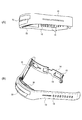
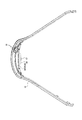
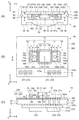
図1(A)、図1(B)、図2に、実施形態1に係る生体情報測定機器(生体情報検出装置)の概略の外観図を示す。図1(A)は、生体情報測定機器を正面方向側から見た図であり、図1(B)は、図1(A)における斜め上方向側から見た図であり、図2は側面方向側から見た図である。
(Embodiment 1)
1. Example of Overall Configuration of Biological Information Measuring Device FIGS. 1A, 1B, and 2 are schematic external views of the biological information measuring device (biological information detecting device) according to the first embodiment. 1A is a view of the biological information measuring device as viewed from the front direction side, FIG. 1B is a view of the living body information measurement device as viewed from an obliquely upward direction side in FIG. 1A, and FIG. It is the figure seen from the direction side.

図1(A)、図1(B)、および図2に示すように本実施形態の生体情報測定機器はバンド部10とケース部30と生体情報測定モジュールとしてのセンサー部40を有する。ケース部30はバンド部10に取り付けられる。センサー部40は、ケース部30に設けられる。また生体情報測定機器は後述する図4に示すように処理部200を有する。処理部200は、ケース部30に設けられ、センサー部40からの検出信号に基づいて生体情報を検出する。なお、本実施形態の生体情報測定機器は図1(A)、図1(B)、および図2の構成に限定されず、その構成要素の一部を省略したり、他の構成要素に置き換えたり、他の構成要素を追加したりするなどの種々の変形実施が可能である。   As shown in FIG. 1A, FIG. 1B, and FIG. 2, the biological information measuring device of this embodiment has a band part 10, a case part 30, and a sensor part 40 as a biological information measuring module. The case part 30 is attached to the band part 10. The sensor unit 40 is provided in the case unit 30. Further, the biological information measuring device has a processing unit 200 as shown in FIG. The processing unit 200 is provided in the case unit 30 and detects biological information based on a detection signal from the sensor unit 40. Note that the biological information measuring device of the present embodiment is not limited to the configuration shown in FIGS. 1A, 1B, and 2, and some of the components are omitted or replaced with other components. Various modifications such as adding other constituent elements are possible.

生体情報測定モジュールとしてのセンサー部40は、図5を用いて後述するように、基板160と、発光部150と、受光部140と、フレーム70としての第1壁部71および第2壁部72と、絞り部80(80a,80b)を有する光検出ユニットと、他の部材とから構成される。図5の例であれば、他の部材とは、透光部材50により実現される凸部52、溝部54、凹部56、押圧抑制部58等である。ただし、本実施形態に係る光検出ユニットがそれらの部材を含む、即ち、センサー部40全体が、光検出ユニットに対応する等の変形実施も可能である。   As will be described later with reference to FIG. 5, the sensor unit 40 serving as a biological information measurement module includes a substrate 160, a light emitting unit 150, a light receiving unit 140, and a first wall unit 71 and a second wall unit 72 serving as a frame 70. And a light detection unit having an aperture 80 (80a, 80b) and other members. In the example of FIG. 5, the other members are a convex portion 52, a groove portion 54, a concave portion 56, a pressing suppression portion 58, and the like realized by the translucent member 50. However, the light detection unit according to the present embodiment includes these members, that is, the sensor unit 40 as a whole can correspond to the light detection unit.

図1および図2に戻る。バンド部10は装着者(以下、ユーザーともいう)の手首に巻き付けて生体情報測定機器を装着するためのものである。バンド部10はバンド穴12、バックル部14を有する。バックル部14はバンド挿入部15と突起部16を有する。ユーザーは、バンド部10の一端側を、バックル部14のバンド挿入部15に挿入し、バンド部10のバンド穴12にバックル部14の突起部16を挿入することで、生体情報測定機器を手首に装着する。この場合、どのバンド穴12に突起部16を挿入するかに応じて、後述するセンサー部40の押圧(手首表面に対する押圧)の大きさが調整される。   Returning to FIG. 1 and FIG. The band unit 10 is for wrapping around a wrist of a wearer (hereinafter also referred to as a user) to wear a biological information measuring device. The band part 10 has a band hole 12 and a buckle part 14. The buckle portion 14 has a band insertion portion 15 and a projection portion 16. The user inserts one end side of the band unit 10 into the band insertion unit 15 of the buckle unit 14 and inserts the protrusion 16 of the buckle unit 14 into the band hole 12 of the band unit 10, thereby attaching the biological information measuring device to the wrist. Attach to. In this case, depending on which band hole 12 the protrusion 16 is inserted into, the magnitude of the pressing (pressing on the wrist surface) of the sensor unit 40 described later is adjusted.

ケース部30は、生体情報測定機器の本体部に相当するものである。ケース部30の内部には、センサー部40、処理部200(図4参照)等の生体情報測定機器の種々の構成部品が設けられる。即ち、ケース部30は、これらの構成部品を収納する筐体である。このケース部30は、例えば手首と反対側に位置するトップケース34と、手首側に位置するボトムケース36を有する。なおケース部30は、トップケース34とボトムケース36に分離される態様のものでなくてもよい。   The case part 30 corresponds to a main body part of the biological information measuring device. Various components of the biological information measuring device such as the sensor unit 40 and the processing unit 200 (see FIG. 4) are provided inside the case unit 30. That is, the case part 30 is a housing for housing these components. The case portion 30 includes, for example, a top case 34 located on the opposite side of the wrist and a bottom case 36 located on the wrist side. The case portion 30 may not be separated from the top case 34 and the bottom case 36.

ケース部30には発光窓部32が設けられている。発光窓部32は透光部材により形成されている。そしてケース部30には、フレキシブル基板に実装された発光部(LED、光検出ユニットの発光部150とは異なる報知用の発光部)が設けられており、この発光部からの光が、発光窓部32を介してケース部30の外部に射出される。   The case part 30 is provided with a light emitting window part 32. The light emitting window 32 is formed of a light transmissive member. The case unit 30 is provided with a light emitting unit (LED, a light emitting unit for notification different from the light emitting unit 150 of the light detection unit) mounted on the flexible substrate, and light from the light emitting unit is transmitted to the light emitting window. It is injected to the outside of the case part 30 through the part 32.

図2に示すようにケース部30には端子部35が設けられている。生体情報測定機器を図示しないクレードルに装着すると、クレードルの端子部とケース部30の端子部35とが電気的に接続される。これによりケース部30に設けられる二次電池(バッテリー)の充電が可能になる。   As shown in FIG. 2, the case portion 30 is provided with a terminal portion 35. When the biological information measuring device is mounted on a cradle (not shown), the terminal part of the cradle and the terminal part 35 of the case part 30 are electrically connected. Thereby, the secondary battery (battery) provided in the case part 30 can be charged.

生体情報測定モジュールとしてのセンサー部40は、例えば被検体の脈波等の生体情報を検出するものである。例えばセンサー部40は、後述する図4、図5に示すように受光部140と発光部150を有する。またセンサー部40は、透光部材50により形成され、被検体の皮膚表面に接触して押圧を与える凸部52を有する。このように凸部52が皮膚表面に押圧を与えた状態で、発光部150が光を射出し、その光が被検体(血管)により反射された光を受光部140が受光し、その受光結果が検出信号として処理部200に出力される。そして処理部200は、センサー部40からの検出信号に基づいて脈波等の生体情報を検出する。そして、センサー部40は、後述する図5(A)に示すように、ケース部30に、例えばOリング55を介して挿入され、保持されている。なお、本実施形態の生体情報測定機器の検出対象となる生体情報は、脈波(脈拍数)には限定されず、生体情報測定機器は、脈波以外の生体情報(例えば血液中の酸素飽和度、体温、心拍等)を検出する装置であってもよい。   The sensor unit 40 as a biological information measurement module detects biological information such as a pulse wave of a subject. For example, the sensor unit 40 includes a light receiving unit 140 and a light emitting unit 150 as shown in FIGS. The sensor unit 40 includes a convex portion 52 that is formed by the translucent member 50 and that makes contact with the skin surface of the subject to apply pressure. The light emitting unit 150 emits light in a state where the convex portion 52 presses the skin surface in this way, and the light receiving unit 140 receives the light reflected by the subject (blood vessel). Is output to the processing unit 200 as a detection signal. The processing unit 200 detects biological information such as a pulse wave based on the detection signal from the sensor unit 40. And the sensor part 40 is inserted and hold | maintained in the case part 30 via the O-ring 55, for example, as shown to FIG. 5 (A) mentioned later. Note that the biological information to be detected by the biological information measuring device of the present embodiment is not limited to the pulse wave (pulse rate), and the biological information measuring device can detect biological information other than the pulse wave (for example, oxygen saturation in blood). Device for detecting temperature, body temperature, heart rate, etc.).

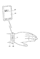
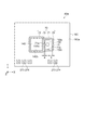
図3は生体情報測定機器400の装着および端末装置420との通信についての概略を示す説明図である。図3に示すように被検体であるユーザーは手首410に生体情報測定機器400を時計のように装着する。図2に示すように、ケース部30の被検体側の面にはセンサー部40が設けられている。従って、生体情報測定機器400が装着されると、センサー部40の凸部52が手首410の皮膚表面に接触して押圧を与え、その状態でセンサー部40の発光部150が光を発光し、受光部140が反射光を受光することで、脈波等の生体情報が検出される。   FIG. 3 is an explanatory diagram showing an outline of the wearing of the biological information measuring device 400 and the communication with the terminal device 420. As shown in FIG. 3, the user who is the subject wears the biological information measuring device 400 on the wrist 410 like a watch. As shown in FIG. 2, a sensor unit 40 is provided on the subject side surface of the case unit 30. Therefore, when the biological information measuring device 400 is attached, the convex portion 52 of the sensor unit 40 contacts and presses the skin surface of the wrist 410, and in this state, the light emitting unit 150 of the sensor unit 40 emits light, When the light receiving unit 140 receives the reflected light, biological information such as a pulse wave is detected.

生体情報測定機器400と端末装置420は通信接続されて、データのやり取りが可能になっている。端末装置420は、例えばスマートフォン、携帯電話機、フューチャーフォン等の携帯型通信端末である。或いは端末装置420は、タブレット型コンピューター等の情報処理端末であってもよい。生体情報測定機器400と端末装置420の通信接続としては、例えばブルートゥース(Bluetooth(登録商標))等の近接無線通信を採用できる。このように生体情報測定機器400と端末装置420が通信接続されることで、端末装置420の表示部430(LCD等)に、脈拍数や消費カロリーなどの各種の情報を表示できる。即ち、センサー部40の検出信号に基づき求められた各種の情報を表示できる。なお脈拍数や消費カロリーなどの情報の演算処理は、生体情報測定機器400において実行してもよいし、その少なくとも一部を端末装置420において実行してもよい。   The biological information measuring device 400 and the terminal device 420 are connected for communication so that data can be exchanged. The terminal device 420 is a portable communication terminal such as a smartphone, a mobile phone, or a future phone. Alternatively, the terminal device 420 may be an information processing terminal such as a tablet computer. As a communication connection between the biological information measuring device 400 and the terminal device 420, for example, proximity wireless communication such as Bluetooth (Bluetooth®) can be employed. In this way, the biological information measuring device 400 and the terminal device 420 are connected by communication, so that various information such as the pulse rate and calorie consumption can be displayed on the display unit 430 (LCD or the like) of the terminal device 420. That is, various information obtained based on the detection signal of the sensor unit 40 can be displayed. The calculation processing of information such as the pulse rate and calorie consumption may be executed by the biological information measuring device 400, or at least a part thereof may be executed by the terminal device 420.

生体情報測定機器400には、発光窓部32が設けられており、報知用の発光体(図示せず)の発光(点灯、点滅)により、各種の情報をユーザーに報知する。例えば消費カロリーなどの情報において脂肪燃焼ゾーンに入った場合や脂肪燃焼ゾーンから出た場合に、これを、発光窓部32を介した発光体の発光により報知する。また端末装置420においてメール等が受信されると、それが端末装置420から生体情報測定機器400に通知される。そして生体情報測定機器400の発光体が発光することで、メール等の受信がユーザーに通知される。   The biological information measuring device 400 is provided with a light emitting window 32, and notifies various kinds of information to the user by light emission (lighting and blinking) of a light emitting body for notification (not shown). For example, when entering the fat burning zone or exiting from the fat burning zone in information such as calories burned, this is notified by light emission of the light emitter through the light emitting window 32. When the terminal device 420 receives a mail or the like, the terminal device 420 notifies the biological information measuring device 400 of it. Then, when the light emitter of the biological information measuring device 400 emits light, the user is notified of reception of e-mail or the like.

このように図3に示す例では、生体情報測定機器400にはLCD等の表示部が設けられておらず、文字や数字等で報知する必要がある情報は、端末装置420の表示部430に表示される。このように図3に示す例では、LCD等の表示部を設けずに、必要最小限の情報を発光体の発光によりユーザーに報知することで、生体情報測定機器400の小型化を実現している。また生体情報測定機器400に表示部を設けないことで、生体情報測定機器400の美観についても向上できる。   As described above, in the example illustrated in FIG. 3, the biological information measuring device 400 is not provided with a display unit such as an LCD, and information that needs to be notified by characters, numbers, or the like is displayed on the display unit 430 of the terminal device 420. Is displayed. As described above, in the example shown in FIG. 3, the biological information measuring device 400 can be downsized by notifying the user of the minimum necessary information by the light emission of the light emitter without providing a display unit such as an LCD. Yes. In addition, since the display unit is not provided in the biological information measuring device 400, the beauty of the biological information measuring device 400 can be improved.

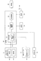
図4に本実施形態の生体情報測定機器の機能ブロック図を示す。図4に示す生体情報測定機器は、生体情報測定モジュールとしてのセンサー部40、体動センサー部170、振動発生部180、処理部200、記憶部240、通信部250、アンテナ252、報知部260を含む。なお本実施形態の生体情報測定機器は、図4に示す構成に限定されず、その構成要素の一部を省略したり、他の構成要素に置き換えたり、他の構成要素を追加するなどの種々の変形実施が可能である。   FIG. 4 shows a functional block diagram of the biological information measuring device of the present embodiment. 4 includes a sensor unit 40, a body motion sensor unit 170, a vibration generation unit 180, a processing unit 200, a storage unit 240, a communication unit 250, an antenna 252, and a notification unit 260 as a biological information measurement module. Including. Note that the biological information measuring device of the present embodiment is not limited to the configuration shown in FIG. 4, and various components such as omitting some of the components, replacing them with other components, and adding other components. Can be implemented.

生体情報測定モジュールとしてのセンサー部40は、脈波等の生体情報を検出するものであり、受光部140、発光部150を含む。これらの受光部140、発光部150等により脈波センサー(光電センサー)が実現される。センサー部40は、脈波センサーにより検出された信号を、脈波検出信号として出力する。   The sensor unit 40 as a biological information measurement module detects biological information such as a pulse wave, and includes a light receiving unit 140 and a light emitting unit 150. A pulse wave sensor (photoelectric sensor) is realized by the light receiving unit 140, the light emitting unit 150, and the like. The sensor unit 40 outputs a signal detected by the pulse wave sensor as a pulse wave detection signal.

体動センサー部170は、種々のセンサーのセンサー情報に基づいて、体動に応じて変化する信号である体動検出信号を出力する。体動センサー部170は、体動センサーとして例えば加速度センサー172を含む。なお、体動センサー部170は、体動センサーとして圧力センサーやジャイロセンサーなどを有していてもよい。   The body motion sensor unit 170 outputs a body motion detection signal that is a signal that changes according to body motion, based on sensor information of various sensors. The body motion sensor unit 170 includes, for example, an acceleration sensor 172 as a body motion sensor. The body motion sensor unit 170 may include a pressure sensor, a gyro sensor, or the like as the body motion sensor.

処理部200は、例えば記憶部240をワーク領域として、各種の信号処理や制御処理を行うものであり、例えばCPU等のプロセッサー或いはASICなどの論理回路により実現できる。処理部200は、信号処理部210と、拍動情報演算部220と、報知制御部230とを含む。   The processing unit 200 performs various signal processing and control processing using the storage unit 240 as a work area, for example, and can be realized by a processor such as a CPU or a logic circuit such as an ASIC. The processing unit 200 includes a signal processing unit 210, a pulsation information calculation unit 220, and a notification control unit 230.

信号処理部210は各種の信号処理(フィルター処理等)を行うものであり、例えば、センサー部40からの脈波検出信号や体動センサー部170からの体動検出信号などに対して信号処理を行う。例えば信号処理部210は体動ノイズ低減部212を含む。体動ノイズ低減部212は、体動センサー部170からの体動検出信号に基づいて、脈波検出信号から、体動に起因したノイズである体動ノイズを低減(除去)する処理を行う。具体的には、例えば適応フィルターなどを用いたノイズ低減処理を行う。   The signal processing unit 210 performs various types of signal processing (filter processing and the like). For example, the signal processing unit 210 performs signal processing on a pulse wave detection signal from the sensor unit 40, a body motion detection signal from the body motion sensor unit 170, and the like. Do. For example, the signal processing unit 210 includes a body movement noise reduction unit 212. Based on the body motion detection signal from the body motion sensor unit 170, the body motion noise reduction unit 212 performs a process of reducing (removing) body motion noise that is noise caused by body motion from the pulse wave detection signal. Specifically, for example, noise reduction processing using an adaptive filter or the like is performed.

拍動情報演算部220は、信号処理部210からの信号等に基づいて、拍動情報の演算処理を行う。拍動情報は例えば脈拍数などの情報である。具体的には、拍動情報演算部220は、体動ノイズ低減部212でのノイズ低減処理後の脈波検出信号に対してFFT等の周波数解析処理を行って、スペクトルを求め、求めたスペクトルにおいて代表的な周波数を心拍の周波数とする処理を行う。求めた周波数を60倍にした値が、一般的に用いられる脈拍数(心拍数)となる。なお、拍動情報は脈拍数そのものには限定されず、例えば脈拍数を表す他の種々の情報(例えば心拍の周波数や周期等)であってもよい。また、拍動の状態を表す情報であってもよく、例えば血液量そのものを表す値を拍動情報としてもよい。   The pulsation information calculation unit 220 performs pulsation information calculation processing based on the signal from the signal processing unit 210 and the like. The pulsation information is information such as the pulse rate. Specifically, the pulsation information calculation unit 220 obtains a spectrum by performing frequency analysis processing such as FFT on the pulse wave detection signal after the noise reduction processing in the body motion noise reduction unit 212, and obtains the spectrum. In FIG. 5, processing is performed in which a representative frequency is a heartbeat frequency. A value obtained by multiplying the obtained frequency by 60 is a commonly used pulse rate (heart rate). Note that the pulsation information is not limited to the pulse rate itself, and may be other various information (for example, the frequency or cycle of the heartbeat) representing the pulse rate, for example. Moreover, the information which represents the state of pulsation may be sufficient, for example, it is good also considering the value showing the blood volume itself as pulsation information.

報知制御部230は報知部260を制御する。報知部260(報知デバイス)は、報知制御部230の制御により、ユーザーに各種の情報を報知する。報知部260としては例えば報知用の発光体を用いることができる。この場合には報知制御部230はLEDに流れる電流を制御することで、発光体の点灯、点滅等を制御する。なお報知部260は、LCD等の表示部やブザー等であってもよい。   The notification control unit 230 controls the notification unit 260. The notification unit 260 (notification device) notifies the user of various types of information under the control of the notification control unit 230. As the notification unit 260, for example, a notification light emitter can be used. In this case, the notification control unit 230 controls lighting, blinking, and the like of the light emitter by controlling the current flowing through the LED. Note that the notification unit 260 may be a display unit such as an LCD, a buzzer, or the like.

また報知制御部230は振動発生部180の制御を行う。振動発生部180は、振動により各種の情報をユーザーに報知するものである。振動発生部180は例えば振動モーター(バイブレーター)により実現できる。振動モーターは、例えば、偏芯した錘を回転させることで振動を発生する。具体的には駆動軸(ローター軸)の両端に偏心した錘を取り付けてモーター自体が揺れるようにする。振動発生部180の振動は報知制御部230により制御される。なお振動発生部180はこのような振動モーターには限定されず、種々の変形実施が可能である。例えばピエゾ素子などにより振動発生部180を実現してもよい。   The notification control unit 230 controls the vibration generation unit 180. The vibration generator 180 notifies the user of various types of information by vibration. The vibration generator 180 can be realized by a vibration motor (vibrator), for example. For example, the vibration motor generates vibration by rotating an eccentric weight. Specifically, eccentric weights are attached to both ends of the drive shaft (rotor shaft) so that the motor itself swings. The vibration of the vibration generator 180 is controlled by the notification controller 230. The vibration generator 180 is not limited to such a vibration motor, and various modifications can be made. For example, the vibration generating unit 180 may be realized by a piezo element or the like.

振動発生部180による振動により、例えば電源オン時のスタートアップの報知、初回の脈波検出の成功の報知、脈波が検出できない状態が一定時間続いた時の警告、脂肪燃焼ゾーンの移動時の報知、電池電圧低下時の警告、起床アラームの通知、或いはスマートフォン等の端末装置からのメールや電話等の通知などが可能になる。なお、これらの情報は、報知用の発光部により報知してもよいし、振動発生部180、発光部の両者で報知してもよい。   For example, a start-up notification when the power is turned on, a notification of the success of the first pulse wave detection, a warning when a pulse wave cannot be detected continues for a certain period of time, a notification when the fat burning zone moves, In addition, a warning at the time of battery voltage drop, a notification of a wake-up alarm, or a notification such as an email or a phone call from a terminal device such as a smartphone can be performed. These pieces of information may be notified by a notification light emitting unit, or may be notified by both the vibration generating unit 180 and the light emitting unit.

通信部250は、図3で説明したように外部の端末装置420との通信処理を行う。例えばブルートゥース(Bluetooth(登録商標))などの規格にしたがった無線通信の処理を行う。具体的には通信部250は、アンテナ252からの信号の受信処理や、アンテナ252への信号の送信処理を行う。この通信部250の機能は通信用のプロセッサー或いはASICなどの論理回路により実現できる。   The communication unit 250 performs communication processing with the external terminal device 420 as described with reference to FIG. For example, a wireless communication process is performed according to a standard such as Bluetooth (registered trademark). Specifically, the communication unit 250 performs a signal reception process from the antenna 252 and a signal transmission process to the antenna 252. The function of the communication unit 250 can be realized by a logic circuit such as a communication processor or ASIC.

2.生体情報測定モジュールとしてのセンサー部の構成例
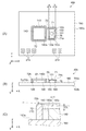
図5を参照して、生体情報測定モジュールとしてのセンサー部40の詳細な構成例について説明する。図5は、センサー部40の構成例1を示す図であり、図5(A)は正断面図、図5(B)は図5(A)のA−Aから見た平面図であり、図5(C)は、図5(B)のB−B断面図である。
2. Configuration Example of Sensor Unit as Biological Information Measurement Module A detailed configuration example of the sensor unit 40 as the biological information measurement module will be described with reference to FIG. 5A and 5B are diagrams illustrating a configuration example 1 of the sensor unit 40, in which FIG. 5A is a front sectional view, and FIG. 5B is a plan view as seen from AA in FIG. FIG. 5C is a cross-sectional view taken along the line BB in FIG.

(センサー部の構成例1)
図5に示す構成例1のセンサー部40は、受光部140と二つの発光部150,154を有する。これらの受光部140および発光部150,154は、所定の間隔を有して図中X軸方向に並び、支持部としての基板160(センサー基板)に実装されている。また、支持部としての基板160の支持面160aと表裏関係をなす裏面160bには、制御部270を構成する回路基板271が実装されている。
(Configuration example 1 of sensor unit)
The sensor unit 40 of the configuration example 1 illustrated in FIG. 5 includes a light receiving unit 140 and two light emitting units 150 and 154. The light receiving unit 140 and the light emitting units 150 and 154 are arranged in the X-axis direction in the drawing with a predetermined interval, and are mounted on a substrate 160 (sensor substrate) as a support unit. Further, a circuit board 271 constituting the control unit 270 is mounted on the back surface 160b having a front and back relationship with the support surface 160a of the substrate 160 as a support unit.

発光部150,154は、対象物(被検体等)に対して光を射出する。そして、受光部140は、対象物を経由した光(反射光、透過光等)を受光する。例えば発光部150,154が光を射出し、その光が対象物(例えば血管)により反射されると、受光部140が、その反射光を受光して検出する。受光部140は、例えばフォトダイオード等の受光素子により実現できる。発光部150,154は、例えばLED等の発光素子により実現できる。例えば受光部140は、半導体の基板に形成されたPN接合のダイオード素子などにより実現できる。この場合に、受光角度を絞るための角度制限フィルターや受光素子に入射する光の波長を制限する波長制限フィルター(光学フィルター膜)を、このダイオード素子上に形成してもよい。   The light emitting units 150 and 154 emit light to an object (such as a subject). The light receiving unit 140 receives light (reflected light, transmitted light, etc.) that has passed through the object. For example, when the light emitting units 150 and 154 emit light and the light is reflected by an object (for example, a blood vessel), the light receiving unit 140 receives and detects the reflected light. The light receiving unit 140 can be realized by a light receiving element such as a photodiode. The light emitting units 150 and 154 can be realized by light emitting elements such as LEDs, for example. For example, the light receiving unit 140 can be realized by a PN junction diode element or the like formed on a semiconductor substrate. In this case, an angle limiting filter for narrowing the light receiving angle and a wavelength limiting filter (optical filter film) for limiting the wavelength of light incident on the light receiving element may be formed on the diode element.

なお、発光部150,154に設けられる集光部としてのドーム型レンズ151,153(広義には集光レンズ)は、発光部150,154に樹脂封止(光透過樹脂で封止)されるLEDチップ(広義には発光素子チップ)からの光を集光するためのレンズである。即ち、表面実装型の発光部150,154では、LEDチップがドーム型レンズ151,153の下方に配置されており、LEDチップからの光は、ドーム型レンズ151,153により集光されて対象物に射出される。これにより、対象物に照射される光の強度を強くすることができることから、光検出ユニットの光学的な効率を向上でき、より正確な測定を行うことが可能となる。   Note that the dome-shaped lenses 151 and 153 (condensing lenses in a broad sense) as condensing units provided in the light emitting units 150 and 154 are resin-sealed (sealed with a light transmitting resin) in the light emitting units 150 and 154. It is a lens for condensing light from an LED chip (light emitting element chip in a broad sense). That is, in the surface-mount type light emitting units 150 and 154, the LED chip is disposed below the dome-shaped lenses 151 and 153, and the light from the LED chip is condensed by the dome-shaped lenses 151 and 153 and the target object. Is injected into. Thereby, since the intensity | strength of the light irradiated to a target object can be strengthened, the optical efficiency of a photon detection unit can be improved and it becomes possible to perform a more exact measurement.

生体情報測定機器として、脈拍計を例にとると、発光部150,154から射出された光は、対象物である被検体の内部を進み、表皮、真皮および皮下組織等で拡散、または散乱する。その後、この光は、血管(被検出部位)に到達し、反射される。この際に、光の一部は血管により吸収される。そして、脈拍の影響により血管での光の吸収率が変化し、反射光の光量も変化するため、受光部140がこの反射光を受光して、その光量の変化を検出することで、生体情報である脈拍数等を検出できるようになる。   Taking a pulsometer as an example of a biological information measuring device, light emitted from the light emitting units 150 and 154 travels inside the subject, which is the object, and diffuses or scatters in the epidermis, dermis, subcutaneous tissue, and the like. . Thereafter, this light reaches the blood vessel (detected site) and is reflected. At this time, part of the light is absorbed by the blood vessels. Then, the light absorption rate in the blood vessel changes due to the influence of the pulse, and the amount of reflected light also changes. Therefore, the light receiving unit 140 receives this reflected light and detects the change in the amount of light, thereby detecting biological information. It becomes possible to detect the pulse rate and the like.

このような生体情報測定機器では、皮膚表面の血流を光学的に測定し、信号化することによって脈波、脈拍などの生体情報を得ている。したがって、測定の正確性や携帯性を向上させるためには、発光部150,154から受光部140までの間の光路における外乱光などのノイズ成分を減少させたり、発光部150,154から受光部140に直接入射される光(直接光等)を減少させたりすることが重要である。   In such a biological information measuring device, blood flow on the skin surface is optically measured and converted into a signal to obtain biological information such as a pulse wave and a pulse. Therefore, in order to improve the accuracy and portability of the measurement, noise components such as disturbance light in the optical path from the light emitting units 150 and 154 to the light receiving unit 140 are reduced, or the light receiving units 150 and 154 to the light receiving unit. It is important to reduce light (such as direct light) that is directly incident on 140.

本構成例1におけるセンサー部40には、受光部140などと同様に、支持部としての基板160(センサー基板)に実装されているフレーム70が設けられている。フレーム70は、受光部140の外周140aを囲む第2壁部72、および発光部150,154の外周150c,154cをそれぞれ囲む第1壁部71を備えている。第2壁部72は、受光部140側に設けられた二つの辺である第1凸部79と、二つの第1凸部79の両端を結ぶ二つの辺73を含み、受光部140の外周140aを囲んでいる。第1壁部71は、第2壁部72を構成する第1凸部79を一辺とし、発光部150に対して第1凸部79と反対側に配置された第2凸部78を備え、発光部150,154の外周150c,154cをそれぞれ囲んでいる。即ち、第1壁部71および第2壁部72は、第1凸部79の部分で接続された一体構造をなしている。この一体構造をなした第1壁部71および第2壁部72によって、フレーム70が構成されている。そして、第1凸部79は、支持面160aからの高さh1を、第2凸部78の支持面160aからの高さh2よりも高くして設けられている。なお、本実施形態においては、高さh1,h2は支持面160aからの高さとしているが、第1凸部79および第2凸部78が接する面を基準として、高さh1,h2を定義してもよい。例えば、図5(B)では、第1凸部79および第2凸部78と、後述する遮光層280の面とが接しており、この遮光層280の面からの高さを高さh1,h2と定義しても良い。   The sensor unit 40 in the first configuration example is provided with a frame 70 mounted on a substrate 160 (sensor substrate) as a support unit, similarly to the light receiving unit 140 and the like. The frame 70 includes a second wall 72 that surrounds the outer periphery 140a of the light receiving unit 140, and a first wall 71 that surrounds the outer peripheries 150c and 154c of the light emitting units 150 and 154, respectively. The second wall portion 72 includes a first convex portion 79 that is two sides provided on the light receiving portion 140 side, and two sides 73 that connect both ends of the two first convex portions 79, and the outer periphery of the light receiving portion 140. 140a is enclosed. The first wall portion 71 includes a second convex portion 78 disposed on the opposite side of the first convex portion 79 with respect to the light emitting portion 150, with the first convex portion 79 constituting the second wall portion 72 as one side. The outer peripheries 150c and 154c of the light emitting units 150 and 154 are enclosed, respectively. That is, the first wall portion 71 and the second wall portion 72 have an integral structure connected at the portion of the first convex portion 79. A frame 70 is constituted by the first wall portion 71 and the second wall portion 72 that form this integral structure. The first convex portion 79 is provided such that the height h1 from the support surface 160a is higher than the height h2 from the support surface 160a of the second convex portion 78. In the present embodiment, the heights h1 and h2 are the heights from the support surface 160a. However, the heights h1 and h2 are defined on the basis of the surface where the first convex portion 79 and the second convex portion 78 are in contact. May be. For example, in FIG. 5B, the first convex portion 79 and the second convex portion 78 are in contact with the surface of the light shielding layer 280 described later, and the height from the surface of the light shielding layer 280 is set to the height h1, It may be defined as h2.

このように、高さの高い第1凸部79が発光部150,154と受光部140との間に配置されていることにより、発光部150,154から射出される光が第1凸部79によって遮られ、受光部140に直接届く(入射する)ことを防止することができる。これにより、対象物に強い光を照射することができるとともに、ノイズの少ない強い光を受光部140に入射させることができ、センサー部40の測定精度を向上させることが可能となる。   As described above, since the first convex portion 79 having a high height is disposed between the light emitting portions 150 and 154 and the light receiving portion 140, the light emitted from the light emitting portions 150 and 154 is the first convex portion 79. It is possible to prevent the light from directly reaching (entering) the light receiving unit 140. Thereby, while being able to irradiate strong light to a target object, strong light with few noises can be incident on the light-receiving part 140, and it becomes possible to improve the measurement precision of the sensor part 40.

また、第1壁部71を構成する第1凸部79と、発光部150,154の受光部140側の第1側面150a,154aとの間の距離aは、第2凸部78と、第1側面150a,154aと反対側の発光部150,154の第2側面150b,154bとの間の距離bよりも小さくなるように構成されている。   Further, the distance a between the first convex portion 79 constituting the first wall portion 71 and the first side surfaces 150a, 154a on the light receiving portion 140 side of the light emitting portions 150, 154 is the second convex portion 78, It is configured to be smaller than the distance b between the first side surfaces 150a and 154a and the second side surfaces 150b and 154b of the light emitting units 150 and 154 on the opposite side.

このような構成によれば、発光部150,154と第1凸部79との間の距離aが小さいため、発光部150,154から第1凸部79(受光部140側)に向かって射出される光が散乱する前に第1凸部79において遮光することができる。これにより、発光部150,154から射出される光が受光部140に直接届く(入射する)ことを防止することができる。これにより、直接光が受光部140に入射することによるノイズ成分を減少させることができ、センサー部40の測定精度を向上させることが可能となる。   According to such a configuration, since the distance a between the light emitting parts 150 and 154 and the first convex part 79 is small, the light is emitted from the light emitting parts 150 and 154 toward the first convex part 79 (the light receiving part 140 side). Before the scattered light is scattered, it can be shielded by the first convex portion 79. As a result, it is possible to prevent light emitted from the light emitting units 150 and 154 from reaching (entering) the light receiving unit 140 directly. Thereby, it is possible to reduce a noise component caused by direct light entering the light receiving unit 140, and to improve the measurement accuracy of the sensor unit 40.

なお、支持面160aからの高さh1の第1凸部79が、受光部140の外周140aの周囲を囲むように配置されていてもよい。また、第1凸部79の支持面160aからの高さh1は、支持面160aから受光部140の頂面(上面)までの高さh3より高いことが望ましい。即ち、第2壁部72は、支持面160aから受光部140の頂面(上面)までの高さh3より高い、支持面160aからの高さh1で受光部140の外周140aの周囲を囲むように設けられることが望ましい。   In addition, the 1st convex part 79 of the height h1 from the support surface 160a may be arrange | positioned so that the circumference | surroundings of the outer periphery 140a of the light-receiving part 140 may be enclosed. The height h1 of the first convex portion 79 from the support surface 160a is preferably higher than the height h3 from the support surface 160a to the top surface (upper surface) of the light receiving unit 140. That is, the second wall portion 72 surrounds the periphery 140a of the light receiving unit 140 with a height h1 higher than the height h3 from the support surface 160a to the top surface (upper surface) of the light receiving unit 140. It is desirable to be provided.

このような第2壁部72(第1凸部79)とすることにより、発光部150,154から射出される直接光や散乱光などの外乱光を第1凸部79の高さh1の第2壁部72によって遮光することができ、例えば発光部150,154から受光部140に直接届く直接光や受光部140に入射される外乱光などのノイズ成分の少ない光を受光部140に入射させることが可能となる。   By using the second wall portion 72 (the first convex portion 79) as described above, disturbance light such as direct light and scattered light emitted from the light emitting portions 150 and 154 can be transmitted to the first convex portion 79 with a height h1. The light can be shielded by the two wall portions 72. For example, light having a small noise component such as direct light directly reaching the light receiving portion 140 from the light emitting portions 150 and 154 or disturbance light incident on the light receiving portion 140 is incident on the light receiving portion 140. It becomes possible.

また、センサー部40においては、測定の対象物(例えば被験者の皮膚)を経由した光を受光部140で的確に受光し、正確な生体情報を取得するためには、対象物から受光部140までの距離(間隔)が重要であり、この距離(間隔)を容易に所定値とすることが可能な構成が求められる。具体的には、対象物から受光部140までの距離(間隔)は、大き過ぎると対象物と受光部140の頂面(上面)との間に空間が生じてしまい、対象物と受光部140の頂面(上面)との間に空気層が存在することで光のロスが大きくなってしまう。一方、対象物から受光部140までの距離(間隔)が小さ過ぎると、対象物の動作などに起因する測定環境の変化や、体動ノイズの影響が大きくなるために、受光部140における受光が不安定になってしまう、あるいはSN比が低下してしまう。上述の構成では、支持面160aからの高さが高い第2壁部72によって受光部140が囲まれているため、第2壁部72(第1凸部79)が対象物のストッパー(度当たり)として機能し、対象物からの反射光を受光部140で的確に受光するために必要である対象物と受光部との間の間隔を、容易に且つ確実に設けることができる。   Further, in the sensor unit 40, the light from the measurement object (for example, the skin of the subject) is accurately received by the light receiving unit 140, and accurate biological information is acquired from the object to the light receiving unit 140. This distance (interval) is important, and a configuration that can easily set this distance (interval) to a predetermined value is required. Specifically, if the distance (interval) from the object to the light receiving unit 140 is too large, a space is generated between the object and the top surface (upper surface) of the light receiving unit 140, and the object and the light receiving unit 140. The loss of light increases due to the presence of an air layer between the top surface (upper surface) of the light source. On the other hand, if the distance (interval) from the object to the light receiving unit 140 is too small, the measurement environment due to the movement of the object and the influence of body movement noise increase, and thus the light receiving unit 140 receives light. It becomes unstable or the SN ratio is lowered. In the above-described configuration, since the light receiving unit 140 is surrounded by the second wall portion 72 having a high height from the support surface 160a, the second wall portion 72 (first convex portion 79) is a stopper of the object (per unit). ) And the interval between the object and the light receiving unit necessary for accurately receiving the reflected light from the object by the light receiving unit 140 can be easily and reliably provided.

また、第1凸部および第2凸部は、生体情報を取得するために有用な光である波長が495nm〜570nmの光を遮光することが好ましい。このように、第1凸部および第2凸部が、波長495nm〜570nmの光(緑光)を遮ることにより、反射光以外の外乱光に含まれるこの波長の光(緑光)の、受光部への入射を減少させることが可能となり、より的確な生体情報を取得することができる。   Moreover, it is preferable that a 1st convex part and a 2nd convex part light-shield the light whose wavelength is 495 nm-570 nm which is useful light in order to acquire biometric information. As described above, the first convex portion and the second convex portion block light (green light) having a wavelength of 495 nm to 570 nm, so that light of this wavelength (green light) included in disturbance light other than reflected light is received by the light receiving portion. Can be reduced, and more accurate biological information can be acquired.

上述の機能を得るためには、フレーム70(第1凸部79および第2凸部78を含む第1壁部71および第2壁部72)は、例えば金属板の板金加工により形成することができる。このように、フレーム70を金属板の板金加工で形成すれば、上述の効果に加え、安価な材料で容易に強度の優れたフレーム70とすることができるとともに、金属のフレーム70によって光の反射が可能となり、発光部150,154から射出された光を効率よく対象物である被検体に照射したり、被検体からの反射光を効率よく受光部140に入射したりすることができる。なお、フレーム70は、他にも金属材料以外の材料として、波長495nm〜570nmの光(緑光)を吸収することができるゴム等の樹脂(天然樹脂および合成樹脂を含む)があげられる。これらの材料は、安価に、また容易に入手が可能であり、且つフレーム70を容易に形成することができる。   In order to obtain the above-described function, the frame 70 (the first wall portion 71 and the second wall portion 72 including the first convex portion 79 and the second convex portion 78) may be formed by, for example, sheet metal processing of a metal plate. it can. Thus, if the frame 70 is formed by sheet metal processing of a metal plate, in addition to the above effects, the frame 70 can be easily made of an inexpensive material and excellent in strength, and the metal frame 70 can reflect light. Thus, the light emitted from the light emitting units 150 and 154 can be efficiently irradiated onto the subject that is the object, and the reflected light from the subject can be efficiently incident on the light receiving unit 140. The frame 70 may be made of a material other than a metal material such as rubber (including natural resin and synthetic resin) that can absorb light (green light) having a wavelength of 495 nm to 570 nm. These materials can be easily obtained at low cost, and the frame 70 can be easily formed.

なお、第1凸部79および第2凸部78を含むフレーム70(第1壁部71および第2壁部72)は、支持部としての基板160と同一材料で一体として形成されていてもよい。このように基板160とフレーム70とが一体に設けられた構成では、基板160とフレーム70とを同時に形成することができるため、製造工程を削減することができ、結果的にセンサー部のコスト低減を図ることが可能となる。   Note that the frame 70 (the first wall portion 71 and the second wall portion 72) including the first convex portion 79 and the second convex portion 78 may be integrally formed of the same material as the substrate 160 as the support portion. . In the configuration in which the substrate 160 and the frame 70 are integrally provided as described above, the substrate 160 and the frame 70 can be formed at the same time, so that the manufacturing process can be reduced, and as a result, the cost of the sensor unit can be reduced. Can be achieved.

上述したように、発光部150は、フレーム70を構成する第1凸部79と第2凸部78との間、且つ第2壁部72の内側に配置されている。このような配置において、発光部150の周囲に設けられている第2壁部72の少なくとも一部に、発光部150から射出された光を反射する反射機能層(図示せず)が設けられていることが好ましい。このようにすれば、発光部150の周囲方向に射出された光が反射機能層によって反射され、反射された光を対象物に向かう光とすることができる。これにより、対象物に向かう光の強度(発光強度)を高めることができ、結果的に生体情報の測定精度を安定化させることが可能となる。   As described above, the light emitting unit 150 is disposed between the first convex portion 79 and the second convex portion 78 constituting the frame 70 and inside the second wall portion 72. In such an arrangement, at least a part of the second wall portion 72 provided around the light emitting unit 150 is provided with a reflective functional layer (not shown) that reflects the light emitted from the light emitting unit 150. Preferably it is. If it does in this way, the light inject | emitted in the peripheral direction of the light emission part 150 will be reflected by the reflection functional layer, and the reflected light can be made into the light which goes to a target object. Thereby, the intensity | strength (light emission intensity) of the light which goes to a target object can be raised, and it becomes possible to stabilize the measurement precision of biological information as a result.

また、発光部150,154の外周150c、154cと第1壁部71との間の領域、および受光部140の外周140aと第2壁部72との間の領域には、透光性を備えた樹脂、例えば透明な樹脂を充填して形成された樹脂層159,149が設けられている。本構成のような枠状の第1壁部71および第2壁部72が設けられていることにより、樹脂が第1壁部71および第2壁部72によって堰き止められ、それより外側への樹脂の流れ出しを防ぐことができ、容易に樹脂を充填することができる。また、このように設けられた樹脂層159,149により、第1壁部71および第2壁部72の強度を高めることができ、さらにはセンサー部40としての強度も高めることができる。なお、樹脂層159,149は、発光部150,154の外周150c,154cと第1壁部71との間の領域、および受光部140の外周140aと第2壁部72との間の領域の少なくとも一方に設けられていればよく、同様な効果を奏する。   The regions between the outer peripheries 150c and 154c of the light emitting units 150 and 154 and the first wall 71 and the region between the outer perimeter 140a of the light receiving unit 140 and the second wall 72 are provided with translucency. Resin layers 159 and 149 formed by filling a transparent resin such as a transparent resin are provided. By providing the frame-like first wall portion 71 and second wall portion 72 as in the present configuration, the resin is blocked by the first wall portion 71 and the second wall portion 72, and the outside is further outward. The resin can be prevented from flowing out and can be filled easily. In addition, the resin layers 159 and 149 thus provided can increase the strength of the first wall portion 71 and the second wall portion 72, and further increase the strength as the sensor portion 40. The resin layers 159 and 149 are formed in regions between the outer peripheries 150c and 154c of the light emitting units 150 and 154 and the first wall 71 and regions between the outer perimeter 140a of the light receiving unit 140 and the second wall 72. As long as it is provided on at least one side, the same effect can be obtained.

また、支持部としての基板160(センサー基板)の支持面160aには、図示しない回路配線によって発光部150,154や受光部140と電気的に接続された第1接続端子274が設けられている。第1接続端子274には、基板160の裏面160bと導通するスルーホール273が設けられている。また、基板160の裏面160bには、第2接続端子275が設けられており、スルーホール273を介して第1接続端子274と電気的に接続されている。このように設けられた回路配線(図示せず)、第1接続端子274、スルーホール273、および第2接続端子275などが導通部として機能する。なお、第1接続端子274および第2接続端子275は、電気的な接続を取るための端子であり、金属層、例えば銅(Cu)層に金(Au)メッキを施すなどによって形成することができる。   A support surface 160a of a substrate 160 (sensor substrate) as a support portion is provided with a first connection terminal 274 that is electrically connected to the light emitting portions 150 and 154 and the light receiving portion 140 by circuit wiring (not shown). . The first connection terminal 274 is provided with a through hole 273 that is electrically connected to the back surface 160 b of the substrate 160. A second connection terminal 275 is provided on the back surface 160 b of the substrate 160 and is electrically connected to the first connection terminal 274 through the through hole 273. The circuit wiring (not shown), the first connection terminal 274, the through hole 273, the second connection terminal 275, and the like thus provided function as a conduction portion. The first connection terminal 274 and the second connection terminal 275 are terminals for electrical connection, and may be formed by applying gold (Au) plating to a metal layer, for example, a copper (Cu) layer. it can.

第2接続端子275には、制御部270を構成する回路基板271が接続されている。制御部270は、ベース部としての回路基板271と、回路基板271に実装された回路素子272を備えている。制御部270は、実施形態1で説明した、例えば処理部200、記憶部240、および通信部250などを含むことができ、脈波等の生体情報を検出するための受発光の制御や信号処理などを行う機能を少なくとも備えることができる。そして、制御部270は、回路基板271の図示しない端子と基板160の第2接続端子275とが電気的な導通を取って接続されている。   A circuit board 271 constituting the control unit 270 is connected to the second connection terminal 275. The control unit 270 includes a circuit board 271 as a base part and a circuit element 272 mounted on the circuit board 271. The control unit 270 can include, for example, the processing unit 200, the storage unit 240, and the communication unit 250 described in the first embodiment, and controls light emission and emission and signal processing for detecting biological information such as pulse waves. Etc. can be provided at least. In the control unit 270, a terminal (not shown) of the circuit board 271 and the second connection terminal 275 of the board 160 are electrically connected to each other.

このような構成では、スルーホール273を介した第2接続端子275により、基板160と制御部270とが接続できる。これにより、例えば基板160の支持面160a側に受光部140、発光部150、第1壁部71、および第2壁部72を配置し、裏面160b側に制御部270を配置することができる。このような配置により、省スペース化、小型化を実現することが可能な、生体情報測定モジュールとしてのセンサー部40bを実現することが可能となる。   In such a configuration, the substrate 160 and the control unit 270 can be connected by the second connection terminal 275 via the through hole 273. Accordingly, for example, the light receiving unit 140, the light emitting unit 150, the first wall 71, and the second wall 72 can be arranged on the support surface 160a side of the substrate 160, and the control unit 270 can be arranged on the back surface 160b side. With such an arrangement, it is possible to realize a sensor unit 40b as a biological information measurement module that can realize space saving and miniaturization.

また、支持部としての基板160(センサー基板)の側面には、図5(A)、図5(C)に示すように外周溝部57が全周に亘って設けられていてもよい。外周溝部57には、例えばOリング53などのシーリング部材が嵌め込まれており、このシーリング部材(Oリング53)を介して基板160がセンサー部40に挿入され取り付けられている。このシーリング部材(Oリング53)により、受光部140、発光部150、フレーム70などが設けられているスペース(後述する凹部56)の防水性を向上させることができ、センサー部40の信頼性を高めることが可能となる。   Further, as shown in FIGS. 5A and 5C, an outer peripheral groove 57 may be provided on the entire side of the side surface of the substrate 160 (sensor substrate) as the support portion. For example, a sealing member such as an O-ring 53 is fitted in the outer peripheral groove portion 57, and the substrate 160 is inserted and attached to the sensor unit 40 through the sealing member (O-ring 53). This sealing member (O-ring 53) can improve the waterproofness of the space (recessed portion 56 described later) in which the light receiving unit 140, the light emitting unit 150, the frame 70 and the like are provided, and the reliability of the sensor unit 40 can be improved. It becomes possible to raise.

また、第2壁部72の少なくとも受光部140側の面には、反射抑制加工を行ってもよい。例えば、第2壁部72の表面(内側面等)の色を、黒色等の所定色にして、光の乱反射を防ぐようにする。或いは、第2壁部72の表面をモスアイ構造にしてもよい。例えば数十〜数百nm周期の凹凸構造を表面に形成して、反射防止構造とする。このような反射抑制加工をすれば、例えば第2壁部72の表面での反射光が迷光となって、検出信号のノイズ成分となってしまう事態を効果的に抑制できる。   Further, reflection suppression processing may be performed on at least the surface of the second wall portion 72 on the light receiving portion 140 side. For example, the color of the surface (inner side surface, etc.) of the second wall portion 72 is set to a predetermined color such as black so as to prevent irregular reflection of light. Or you may make the surface of the 2nd wall part 72 into a moth eye structure. For example, an uneven structure having a period of several tens to several hundreds of nanometers is formed on the surface to form an antireflection structure. By performing such reflection suppression processing, for example, it is possible to effectively suppress a situation in which reflected light on the surface of the second wall portion 72 becomes stray light and becomes a noise component of the detection signal.

前述でも述べたが、受光部140、発光部150、およびフレーム70は、支持部としての基板160(センサー基板)の支持面(表面)160aに実装される。基板160は、例えばリジッド基板である。基板160には、受光部140の信号・電源の端子(図示せず)と接続するための端子(図示せず)や、外部のメイン基板との間で信号・電源を接続するための端子(図示せず)が設けられている。例えば受光部140の端子と基板160の端子とは、ワイヤボンディング等により接続される。このように、受光部140、発光部150、およびフレーム70などが、基板160に実装(支持)されていることにより、発光部150および受光部140と測定対象物との距離が短くなり、光に混入するノイズを減少させることができ、測定精度を向上させることが可能となる。   As described above, the light receiving unit 140, the light emitting unit 150, and the frame 70 are mounted on a support surface (front surface) 160a of a substrate 160 (sensor substrate) as a support unit. The substrate 160 is, for example, a rigid substrate. The board 160 has terminals (not shown) for connecting to signal / power terminals (not shown) of the light receiving unit 140 and terminals (not shown) for connecting signals / power to an external main board (not shown). (Not shown) is provided. For example, the terminals of the light receiving unit 140 and the terminals of the substrate 160 are connected by wire bonding or the like. As described above, since the light receiving unit 140, the light emitting unit 150, the frame 70, and the like are mounted (supported) on the substrate 160, the distance between the light emitting unit 150 and the light receiving unit 140 and the measurement object is shortened, and the light Noise can be reduced, and measurement accuracy can be improved.

また、基板160は、支持面(表面)160aに沿って設けられた遮光層280を備えている。遮光層280は、基板160を平面視したときに、少なくとも受光部140や発光部150と重なる領域に設けられていることが好ましく、本例では、第1接続端子274、スルーホール273、および第2接続端子275などが設けられている部分を除いた領域に備えられている。遮光層280は、図5(C)に示すような、例えば、支持面160a側に設けられた導電層としての金属層281と、金属層281の上面に設けられた絶縁層282の二層構成によって実現できるが、その構成は問わない。図示しないが、例えば支持面160aに絶縁層を設け、その上に金属層を設け、さらに金属層上に絶縁層を設ける多層構成(三層構成)を用いたり、遮光層280を裏面160b側に設けたりすることもできる。このような遮光層280を設けることにより、基板160から反射されたり、基板160を透過したりする外乱光を遮光することができ、的確な生体情報を取得することが可能となる。なお、遮光層280に含まれる導電層としての金属層281は、例えば接地電極などとして用いることができ、遮光効果に加えて、例えば基板160における静電気などの帯電を防止することが可能となり、静電気などによる誤計測を防止することが可能となる。   The substrate 160 includes a light shielding layer 280 provided along a support surface (front surface) 160a. The light shielding layer 280 is preferably provided in a region that overlaps at least the light receiving unit 140 and the light emitting unit 150 when the substrate 160 is viewed in plan view. In this example, the light shielding layer 280 includes the first connection terminal 274, the through hole 273, It is provided in a region excluding a portion where the two connection terminals 275 and the like are provided. As shown in FIG. 5C, the light shielding layer 280 includes, for example, a two-layer structure of a metal layer 281 as a conductive layer provided on the support surface 160a side and an insulating layer 282 provided on the upper surface of the metal layer 281. However, the configuration is not limited. Although not shown, for example, a multilayer structure (three-layer structure) in which an insulating layer is provided on the support surface 160a, a metal layer is provided thereon, and an insulating layer is further provided on the metal layer, or the light shielding layer 280 is disposed on the back surface 160b side. It can also be provided. By providing such a light shielding layer 280, disturbance light reflected from the substrate 160 or transmitted through the substrate 160 can be shielded, and accurate biological information can be acquired. Note that the metal layer 281 as a conductive layer included in the light shielding layer 280 can be used as, for example, a ground electrode, and in addition to the light shielding effect, for example, charging such as static electricity on the substrate 160 can be prevented. It is possible to prevent erroneous measurement due to the above.

また、生体情報を取得するために有用な光である波長495nm〜570nmの光(緑光)を、基板160が遮ることが好ましい。基板160が波長495nm〜570nmの光を遮ることにより、反射光以外の外乱光に含まれるこの波長の光(緑光)の、受光部への入射を減少させることが可能となり、より的確な生体情報を取得することができる。このような性質を有する基板160は、その基材を495nm〜570nmの波長を通過させない材質にしたり、支持面160aや裏面160bに495nm〜570nmの波長を反射または吸収する性質の樹脂層や金属層などを設けたりすることによって実現することができる。   In addition, it is preferable that the substrate 160 blocks light (green light) having a wavelength of 495 nm to 570 nm, which is light useful for acquiring biological information. When the substrate 160 blocks light with a wavelength of 495 nm to 570 nm, it becomes possible to reduce the incidence of light of this wavelength (green light) included in disturbance light other than reflected light to the light receiving unit, and more accurate biological information. Can be obtained. The substrate 160 having such a property is made of a material that does not allow the base material to pass a wavelength of 495 nm to 570 nm, or a resin layer or a metal layer that reflects or absorbs a wavelength of 495 nm to 570 nm on the support surface 160a or the back surface 160b. It is realizable by providing etc.

また、図5(A)に示すように、センサー部40には絞り部80a,80bが設けられていてもよい。絞り部80は、被検体とセンサー部40の間の光路において、被検体からの光を絞ったり、発光部150からの光を絞ったりする。図5では、絞り部80a,80bは、透光部材50と発光部150の間に設けられている。但し、絞り部80a,80bを透光部材50と被検体との間や透光部材50内に設けてもよい。   In addition, as shown in FIG. 5A, the sensor unit 40 may be provided with apertures 80a and 80b. The diaphragm unit 80 squeezes light from the subject or light from the light emitting unit 150 in the optical path between the subject and the sensor unit 40. In FIG. 5, the aperture portions 80 a and 80 b are provided between the translucent member 50 and the light emitting portion 150. However, the diaphragm portions 80 a and 80 b may be provided between the light transmitting member 50 and the subject or in the light transmitting member 50.

図5(A)に示す透光部材50は、生体情報測定機器の被検体に接触する側の面に設けられ、被検体からの光を透過する。また透光部材50は、被検体の生体情報の測定時に、被検体に接触する。例えば透光部材50の凸部52(検出窓)が被検体に接触する。なお凸部52の表面形状は、曲面形状(球面形状)であることが望ましいが、これに限定されるものではなく、種々の形状を採用できる。また、透光部材50は、被検体からの光の波長を透過することができるものであればよく、透明な材料を用いてもよいし、有色の材料を用いてもよい。   The translucent member 50 shown in FIG. 5A is provided on the surface of the biological information measuring device that is in contact with the subject, and transmits light from the subject. The translucent member 50 contacts the subject when measuring the biological information of the subject. For example, the convex part 52 (detection window) of the translucent member 50 contacts the subject. The surface shape of the convex portion 52 is desirably a curved surface shape (spherical shape), but is not limited to this, and various shapes can be adopted. The translucent member 50 may be any member that can transmit the wavelength of light from the subject, and may be a transparent material or a colored material.

透光部材50の凸部52の周囲には、押圧変動等を抑制するための溝部54が設けられている。また、透光部材50において凸部52が設けられる側の面を第1の面とした場合に、透光部材50は、その第1の面の裏側の第2の面において凸部52に対応する位置に、凹部56を有している。この凹部56のスペースに、受光部140、発光部150、フレーム70、絞り部(80a,80b)が設けられている。   Around the convex portion 52 of the translucent member 50, a groove portion 54 is provided for suppressing pressure fluctuation and the like. Further, when the surface on the side where the convex portion 52 is provided in the translucent member 50 is the first surface, the translucent member 50 corresponds to the convex portion 52 on the second surface on the back side of the first surface. A recessed portion 56 is provided at a position to be used. In the space of the recess 56, a light receiving unit 140, a light emitting unit 150, a frame 70, and a diaphragm unit (80a, 80b) are provided.

また生体情報測定機器の被検体側の面には、凸部52が被検体(手首の肌)に与える押圧を抑制する押圧抑制部58が設けられている。図5では押圧抑制部58は、透光部材50の凸部52を囲むように設けられている。そして、凸部52は、押圧抑制部(押圧抑制面)58よりも被検体側に突出している。   Further, on the surface on the subject side of the biological information measuring device, a pressure suppressing portion 58 that suppresses the pressure applied by the convex portion 52 to the subject (the wrist skin) is provided. In FIG. 5, the pressing suppression portion 58 is provided so as to surround the convex portion 52 of the translucent member 50. The convex portion 52 protrudes further toward the subject side than the press suppressing portion (press suppressing surface) 58.

このような凸部52を設けることで、例えば静脈消失点を超えるための初期押圧を被検体に対して与えることが可能になる。また、凸部52が被検体に与える押圧を抑制するための押圧抑制部58を設けることで、生体情報測定機器により生体情報の測定を行う使用範囲において、押圧変動を最小限に抑えることが可能になり、ノイズ成分等の低減を図れる。また、凸部52が押圧抑制部58から突出していれば、凸部52が被検体に接触して初期押圧を与えた後に、押圧抑制部58が被検体に接触して、凸部52が被検体に与える押圧を抑制できるようになる。ここで静脈消失点とは、被検体に凸部52を接触させ押圧を次第に強くした時に、脈波信号に重畳された静脈に起因する信号が消失、または脈波測定に影響しない程度に小さくなる点のことである。   By providing such a convex portion 52, for example, it is possible to give an initial pressure to the subject to exceed the vein vanishing point. In addition, by providing the pressure suppression unit 58 for suppressing the pressure applied to the subject by the convex portion 52, it is possible to minimize the pressure fluctuation in the usage range in which the biological information is measured by the biological information measuring device. Therefore, noise components and the like can be reduced. Further, if the convex portion 52 protrudes from the pressing suppression portion 58, after the convex portion 52 comes into contact with the subject and gives an initial press, the pressing suppression portion 58 comes into contact with the subject and the convex portion 52 is covered. The pressure applied to the specimen can be suppressed. Here, the vein vanishing point is reduced to such an extent that the signal caused by the vein superimposed on the pulse wave signal disappears or does not affect the pulse wave measurement when the convex portion 52 is brought into contact with the subject and the pressure is gradually increased. It is a point.

また、センサー部40のケース部30に挿入される外周面には、外周溝部59が全周に亘って設けられている。外周溝部59には、例えばOリング55などのシーリング部材が配置され、ケース部30にこのシーリング部材(Oリング55)を介して挿入されている。このように、シーリング部材(Oリング55)を介してケース部30に保持することにより、防水性を高めることができる。   In addition, an outer peripheral groove portion 59 is provided over the entire periphery on the outer peripheral surface inserted into the case portion 30 of the sensor unit 40. For example, a sealing member such as an O-ring 55 is disposed in the outer peripheral groove portion 59, and is inserted into the case portion 30 via this sealing member (O-ring 55). Thus, waterproofness can be improved by hold | maintaining to the case part 30 via a sealing member (O-ring 55).

上述した実施形態1の構成によれば、支持面160aからの高さが、第2凸部78より高い第1凸部79が発光部150と受光部140との間に配置されているため、発光部150から射出された光が第1凸部79によって遮られ易く、射出された光が受光部140に直接届く(入射する)ことを防止することができる。また、第2壁部72(第1凸部79)によって受光部140が囲まれているため、散乱光などの外乱光を遮光することができ、受光部140の受光において、外乱光によるノイズ成分を減少させることが可能となる。また、第2壁部72(第1凸部79)によって受光部140が囲まれているため、第2壁部72(第1凸部79)が対象物のストッパー(度当たり)として機能し、対象物からの反射光を受光部140において、的確に受光するために必要である対象物と受光部140との間の間隔を、容易に且つ確実に設けることができる。
これらにより、センサー部40の測定精度をより向上させることが可能となり、的確な生体情報を取得することができる生体情報測定モジュールとしてのセンサー部40、およびセンサー部40を備えた生体情報測定機器を提供することが可能となる。
According to the configuration of the first embodiment described above, since the first convex portion 79 whose height from the support surface 160a is higher than the second convex portion 78 is disposed between the light emitting portion 150 and the light receiving portion 140, The light emitted from the light emitting unit 150 is easily blocked by the first convex portion 79, and the emitted light can be prevented from reaching (entering) the light receiving unit 140 directly. In addition, since the light receiving unit 140 is surrounded by the second wall portion 72 (first convex portion 79), disturbance light such as scattered light can be shielded, and noise components due to disturbance light are received in the light reception of the light receiving unit 140. Can be reduced. Moreover, since the light receiving part 140 is surrounded by the second wall part 72 (first convex part 79), the second wall part 72 (first convex part 79) functions as a stopper (per degree) of the object, The interval between the object and the light receiving unit 140 necessary for accurately receiving the reflected light from the object in the light receiving unit 140 can be easily and reliably provided.
As a result, the measurement accuracy of the sensor unit 40 can be further improved, the sensor unit 40 as a biological information measurement module capable of acquiring accurate biological information, and a biological information measurement device including the sensor unit 40. It becomes possible to provide.

(センサー部の変形例)
次に、センサー部40の変形例について、図6、図7および図8を参照して説明する。図6は、センサー部の変形例1を示す平面図である。図7は、センサー部40の変形例2を示し、図7(A)は平面図、図7(B)は図7(A)の正断面図、図7(C)は図7(B)の部分拡大図(正断面図)。図8は、センサー部40の変形例3を示し、図8(A)は平面図、図8(B)は図8(A)の正面図である。なお、図6、図7、および図8では、受光部140、発光部150、およびフレームとしての第1壁部71、第2壁部72の配置を中心に図示しており、他の構成要素の図示を省略している。また、前述の実施形態1と同様な構成については同符号を付しており、その説明を省略することもある。また、以下の変形例においても、第1凸部79の高さh1、受光部140の高さh3、発光部150の高さh2、発光部150と第2壁部72との間の距離a、発光部150と第1壁部71との間の距離bなどに係る構成およびそれらの関係は、上述の第1実施形態と同様に適用することができる。
(Modification of sensor part)
Next, a modified example of the sensor unit 40 will be described with reference to FIG. 6, FIG. 7, and FIG. FIG. 6 is a plan view showing Modification 1 of the sensor unit. 7 shows a second modification of the sensor unit 40, FIG. 7A is a plan view, FIG. 7B is a front sectional view of FIG. 7A, and FIG. 7C is FIG. 7B. The elements on larger scale (front sectional drawing). 8 shows a third modification of the sensor unit 40, FIG. 8 (A) is a plan view, and FIG. 8 (B) is a front view of FIG. 8 (A). 6, 7, and 8, the light receiving unit 140, the light emitting unit 150, and the arrangement of the first wall 71 and the second wall 72 as frames are mainly illustrated, and other components Is omitted. In addition, the same components as those in the first embodiment are denoted by the same reference numerals, and the description thereof may be omitted. Also in the following modified examples, the height h1 of the first convex portion 79, the height h3 of the light receiving portion 140, the height h2 of the light emitting portion 150, and the distance a between the light emitting portion 150 and the second wall portion 72. The configuration related to the distance b between the light emitting unit 150 and the first wall 71 and the relationship between them can be applied in the same manner as in the first embodiment.

(変形例1)
先ず、図6を参照してセンサー部40の変形例1について説明する。本変形例1の構成は、前述の実施形態1と比し、発光部150が一つであること、および、それに伴いフレーム70としての第1壁部71および第2壁部72の構成が異なる。変形例1のセンサー部40aは、支持部としての基板160の支持面160aに受光部140と発光部150とが並んで実装されている。さらに、基板160の支持面160aには、フレーム70が設けられている。フレーム70は、受光部140の外周140bを囲む第2壁部72、および発光部150の外周150cを囲む第1壁部71を備えている。第2壁部72は、受光部140側に設けられた辺である第1凸部79を有し、受光部140の外周140bを囲んでいる。第1壁部71は、第2壁部72を構成する第1凸部79を一辺とし、発光部150に対して第1凸部79と反対側に配置された第2凸部78を備え、発光部150の外周150cを囲んでいる。即ち、第1壁部71および第2壁部72は、第1凸部79の部分で接続された一体構造をなしている。この一体構造をなした第1壁部71および第2壁部72によって、フレーム70が構成されている。
(Modification 1)
First, a first modification of the sensor unit 40 will be described with reference to FIG. The configuration of the first modification is different from that of the first embodiment described above in that there is one light emitting unit 150 and the configuration of the first wall portion 71 and the second wall portion 72 as the frame 70 is accordingly different. . In the sensor unit 40a of Modification 1, the light receiving unit 140 and the light emitting unit 150 are mounted side by side on a support surface 160a of a substrate 160 as a support unit. Further, a frame 70 is provided on the support surface 160 a of the substrate 160. The frame 70 includes a second wall 72 that surrounds the outer periphery 140 b of the light receiving unit 140 and a first wall 71 that surrounds the outer periphery 150 c of the light emitting unit 150. The second wall portion 72 has a first convex portion 79 that is a side provided on the light receiving portion 140 side, and surrounds the outer periphery 140b of the light receiving portion 140. The first wall portion 71 includes a second convex portion 78 disposed on the opposite side of the first convex portion 79 with respect to the light emitting portion 150, with the first convex portion 79 constituting the second wall portion 72 as one side. The outer periphery 150c of the light emitting unit 150 is surrounded. That is, the first wall portion 71 and the second wall portion 72 have an integral structure connected at the portion of the first convex portion 79. A frame 70 is constituted by the first wall portion 71 and the second wall portion 72 that form this integral structure.

(変形例2)
次に、図7(A)〜図7(C)を参照してセンサー部40の変形例2について説明する。本変形例2の構成は、前述の実施形態1と比し、発光部150が一つであること、およびフレームとしての第1壁部71および第2壁部72が個別の構成であることが異なる。変形例2のセンサー部40bは、支持部としての基板160の支持面160aに受光部140と発光部150とが並んで実装されている。さらに、基板160の支持面160aには、受光部140の外周140aを囲む第2壁部72、および発光部150の外周150cを囲む第1壁部71を備えている。第2壁部72は、支持面160aからの高さが同じである壁部が受光部140の外周140aを囲んでいる。また、第1壁部71は、受光部140側に設けられた第1凸部79と、発光部150に対して第1凸部79と反対側に配置された第2凸部78を備え、発光部150の外周150cを囲んでいる。前述の実施形態1と同様に、第1凸部79の支持面160aからの高さは、第2凸部78の支持面160aからの高さよりも高く構成されている。
(Modification 2)
Next, Modification 2 of the sensor unit 40 will be described with reference to FIGS. 7 (A) to 7 (C). Compared with the above-described first embodiment, the configuration of the second modification example includes one light-emitting unit 150 and the first wall 71 and the second wall 72 as frames are configured separately. Different. In the sensor unit 40b of Modification 2, the light receiving unit 140 and the light emitting unit 150 are mounted side by side on a support surface 160a of a substrate 160 as a support unit. Further, the support surface 160 a of the substrate 160 includes a second wall portion 72 that surrounds the outer periphery 140 a of the light receiving unit 140 and a first wall portion 71 that surrounds the outer periphery 150 c of the light emitting unit 150. In the second wall portion 72, the wall portion having the same height from the support surface 160 a surrounds the outer periphery 140 a of the light receiving portion 140. The first wall portion 71 includes a first convex portion 79 provided on the light receiving portion 140 side, and a second convex portion 78 disposed on the opposite side of the light emitting portion 150 from the first convex portion 79, The outer periphery 150c of the light emitting unit 150 is surrounded. Similar to the first embodiment, the height of the first convex portion 79 from the support surface 160a is configured to be higher than the height of the second convex portion 78 from the support surface 160a.

前述の実施形態1および変形例においても同様であるが、図7(C)に示すように、基板160の支持面160aに実装された受光部140を囲む第2壁部72は、その頂面(上面)72bで対象物である被検体、例えば被験者の皮膚411を保持し、受光部140の上部に所望の空間を形成することができる。詳細に述べると、被験者の皮膚411を経由した光を受光部140で的確に受光し、正確な生体情報を取得するためには、対象物から受光部140までの距離(間隔CL)が重要であり、この距離(間隔CL)を容易に所定値とすることが可能な構成が求められる。具体的には、対象物から受光部140までの距離(間隔CL)は、大き過ぎるとこの間を通過する光にノイズ成分が混在しやすくなり、小さ過ぎるもしくは対象物と受光部140の頂面(上面)140cとが接触してしまうと受光部140における受光ができなくなってしまう。しかしながら、受光部140を囲む第2壁部72によって、被験者の皮膚411を保持することができ、皮膚411から受光部140までの距離(間隔CL)を確保して、受光部140の上部に所望の空間を形成することができる。   The same applies to the first embodiment and the modification described above, but as shown in FIG. 7C, the second wall portion 72 surrounding the light receiving portion 140 mounted on the support surface 160a of the substrate 160 has a top surface. The upper surface 72b holds the subject, for example, the skin 411 of the subject, and can form a desired space above the light receiving unit 140. More specifically, the distance (interval CL) from the object to the light receiving unit 140 is important in order to accurately receive the light passing through the skin 411 of the subject by the light receiving unit 140 and obtain accurate biological information. There is a need for a configuration that can easily set this distance (interval CL) to a predetermined value. Specifically, if the distance (interval CL) from the object to the light receiving unit 140 is too large, noise components are likely to be mixed in the light passing therethrough, and it is too small or the top surface of the object and the light receiving unit 140 ( If the upper surface 140c comes into contact, the light receiving unit 140 cannot receive light. However, the skin 411 of the subject can be held by the second wall portion 72 that surrounds the light receiving unit 140, and a distance (interval CL) from the skin 411 to the light receiving unit 140 is ensured, and the upper portion of the light receiving unit 140 is desired. Can be formed.

また、第1壁部71および第2壁部72の上部の開放端面である頂面71b,72bの断面形状が、角部の無い滑らかな形状、例えば円弧形状などの湾曲形状(曲線形状)であることが好ましい。頂面71b,72bの断面形状を湾曲形状とすることにより、第1壁部71および第2壁部72が、測定対象物に接する場合に、湾曲部分(アール面)が接触するため、例えばユーザーの皮膚へのくい込みなどを生じ難くすることができ、違和感を減少させることができる。これにより、センサーモジュールとしてのセンサー部40bまたはこのセンサー部40bを搭載した生体情報測定機器を装着する場合のユーザーの装着感を向上させることが可能となる。なお、この第1壁部71および第2壁部72の上部の開放端面である頂面71b,72bが湾曲形状(曲線形状)である構成は、本明細書中にて説明する実施形態や他の変形例においても適用することができる。   Moreover, the cross-sectional shape of the top surfaces 71b and 72b which are the open end surfaces of the upper part of the first wall part 71 and the second wall part 72 is a smooth shape without corners, for example, a curved shape (curved shape) such as an arc shape. Preferably there is. By making the cross-sectional shapes of the top surfaces 71b and 72b curved, when the first wall 71 and the second wall 72 are in contact with the object to be measured, the curved portion (the rounded surface) comes into contact with, for example, a user. It is possible to make it difficult for the skin to bite into the skin and reduce the sense of incongruity. As a result, it is possible to improve the user's wearing feeling when wearing the sensor unit 40b as a sensor module or a biological information measuring device equipped with the sensor unit 40b. The configuration in which the top surfaces 71b and 72b, which are the open end surfaces at the top of the first wall portion 71 and the second wall portion 72, have a curved shape (curved shape) is the embodiment described in this specification and others. This modification can also be applied.

また、本変形例2においても、発光部150の外周150cと第1壁部71との間の領域、および受光部140の外周140aと第2壁部72との間の領域には、透光性を備えた樹脂、例えば透明な樹脂を充填して形成された樹脂層159,149が設けられていてもよい。   In the second modification as well, the region between the outer periphery 150 c of the light emitting unit 150 and the first wall 71 and the region between the outer periphery 140 a of the light receiving unit 140 and the second wall 72 are not transparent. Resin layers 159 and 149 formed by filling a resin having a property such as a transparent resin may be provided.

(変形例3)
次に、図8(A)、図8(B)を参照してセンサー部40の変形例2について説明する。本変形例2の構成は、前述の実施形態1と比し、発光部150が一つであること、および第1壁部71および第2壁部72が個別、且つ発光部150および受光部140を囲んでいない構成であることが異なる。
(Modification 3)
Next, a second modification of the sensor unit 40 will be described with reference to FIGS. 8A and 8B. The configuration of the second modification is different from that of the first embodiment described above in that there is one light emitting unit 150, the first wall 71 and the second wall 72 are individually, and the light emitting unit 150 and the light receiving unit 140. It is different that the configuration does not enclose.

変形例3のセンサー部40cは、支持部としての基板160の支持面160aに受光部140と発光部150とが並んで実装されている。さらに、基板160の支持面160aには、第2壁部72、および第1壁部71を備えている。第2壁部72は、受光部140と発光部150との間にあって、受光部140の外周140aと発光部150の第1側面150aに沿って延在する壁面を有している。第1壁部71は、発光部150に対して第2壁部72と反対側に設けられている。なお、本変形例3では、第1壁部71が第1凸部79に相当し、第2壁部72が第2凸部78に相当する。第2壁部72、および第1壁部71は、前述の実施形態1と同様に、第2壁部72の支持面160aからの高さが、第1壁部71の支持面160aからの高さよりも高くなるように構成されている。そして、発光部150の受光部140側の第1側面150aと、第2壁部72との間の距離aは、第1側面150aと反対側の発光部150の側面150cと、第1壁部71との間の距離bよりも小さくなるように構成されている。   In the sensor unit 40c of Modification 3, the light receiving unit 140 and the light emitting unit 150 are mounted side by side on a support surface 160a of a substrate 160 as a support unit. Further, the support surface 160 a of the substrate 160 includes a second wall portion 72 and a first wall portion 71. The second wall portion 72 is provided between the light receiving portion 140 and the light emitting portion 150 and has a wall surface extending along the outer periphery 140 a of the light receiving portion 140 and the first side surface 150 a of the light emitting portion 150. The first wall portion 71 is provided on the side opposite to the second wall portion 72 with respect to the light emitting portion 150. In the third modification, the first wall portion 71 corresponds to the first convex portion 79 and the second wall portion 72 corresponds to the second convex portion 78. As in the first embodiment, the second wall 72 and the first wall 71 have a height from the support surface 160a of the second wall 72 that is higher than the support surface 160a of the first wall 71. It is comprised so that it may become higher than this. And the distance a between the 1st side 150a by the side of the light-receiving part 140 of the light emission part 150, and the 2nd wall part 72 is the side 150c of the light emission part 150 on the opposite side to the 1st side 150a, and the 1st wall part. 71 is configured to be smaller than the distance b to 71.

このような構成によれば、発光部150と第2壁部72(第1凸部79)との間の距離aが小さいため、発光部150から第2壁部72(受光部140側)に向かって射出される光が散乱する前に第2壁部72において遮光することができる。これにより、発光部150から射出される光が受光部140に直接届く(入射する)ことを防止することができる。   According to such a configuration, since the distance a between the light emitting unit 150 and the second wall portion 72 (first convex portion 79) is small, the light emitting portion 150 moves to the second wall portion 72 (light receiving portion 140 side). The light emitted toward the second wall 72 can be shielded before being scattered. Thereby, it is possible to prevent the light emitted from the light emitting unit 150 from reaching (entering) the light receiving unit 140 directly.

上述した変形例1から変形例3の構成のセンサー部40a,40b,40cにおいても、実施形態1のセンサー部40と同様に、支持面160aからの高さが、第2凸部78より高い第1凸部79が発光部150と受光部140との間に配置されているため、発光部150から射出された光が第1凸部79によって遮られ易く、射出された光が受光部140に直接届く(入射する)ことを防止することができる。   Also in the sensor units 40a, 40b, and 40c having the configurations of the first to third modifications described above, the height from the support surface 160a is higher than that of the second convex portion 78 in the same manner as the sensor unit 40 of the first embodiment. Since the first convex portion 79 is disposed between the light emitting portion 150 and the light receiving portion 140, the light emitted from the light emitting portion 150 is easily blocked by the first convex portion 79, and the emitted light is transmitted to the light receiving portion 140. Direct arrival (incident) can be prevented.

(実施形態2)
次に、本発明の実施形態2について図面を用いて説明する。
実施形態2に係る生体情報測定機器は、前述の実施形態1と同様に、生体情報を測定される生体(例えば人体)に装着され、脈拍(心拍数)等の生体情報を測定する心拍数監視装置である。なお、以下に示す各図においては、各構成要素を図面上で認識され得る程度の大きさとするため、各構成要素の寸法や比率を実際の構成要素とは適宜に異ならせて記載する場合がある。また、以下の実施形態2〜5においても、実施形態1で説明した第2壁部72(第2凸部78)の高さh2、第1壁部71(第1凸部79)の高さh1、および受光部140の高さh3、発光部150と第2壁部72との間の距離a、発光部150と第1壁部71との間の距離bなど、フレーム70と発光部150と受光部140と、に係る構成は、同様に適用することができる。
(Embodiment 2)
Next, Embodiment 2 of the present invention will be described with reference to the drawings.
The biological information measuring apparatus according to the second embodiment is mounted on a living body (for example, a human body) whose biological information is measured, and monitors the biological information such as a pulse (heart rate), as in the first embodiment. Device. In each figure shown below, the size and ratio of each component may be described differently from the actual component in order to make each component large enough to be recognized on the drawing. is there. Also in the following second to fifth embodiments, the height h2 of the second wall portion 72 (second convex portion 78) described in the first embodiment and the height of the first wall portion 71 (first convex portion 79) are described. h1 and the height h3 of the light receiving part 140, the distance a between the light emitting part 150 and the second wall part 72, the distance b between the light emitting part 150 and the first wall part 71, and the like. The configuration relating to the light receiving unit 140 can be similarly applied.

まず、実施形態2に係る生体情報測定機器としての心拍数監視装置1010について説明する前に、図9を用いて実施形態2に係る生体情報測定機器としての心拍数監視装置の従来例について説明する。   First, before describing the heart rate monitoring apparatus 1010 as the biological information measuring apparatus according to the second embodiment, a conventional example of the heart rate monitoring apparatus as the biological information measuring apparatus according to the second embodiment will be described with reference to FIG. .

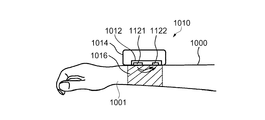
図9は、心拍数監視装置を装着しているユーザー(被験者)1000(同図では、ユーザーの腕を示す)の、生理的パラメーター(生体情報)を測定する従来例の生体情報測定機器としての心拍数監視装置1010を示す断面図である。心拍数監視装置1010は、ユーザー1000の少なくとも一つの生理的パラメーターとしての心拍数を計測するセンサー1012と、センサー1012を収納しているケース1014を備えている。心拍数監視装置1010は、固定部1016(例えばバンド)によって、ユーザー1000の腕1001に装着される。   FIG. 9 shows a conventional biological information measuring device for measuring physiological parameters (biological information) of a user (subject) 1000 (showing the user's arm in the figure) wearing a heart rate monitoring device. It is sectional drawing which shows the heart rate monitoring apparatus 1010. FIG. The heart rate monitoring apparatus 1010 includes a sensor 1012 that measures a heart rate as at least one physiological parameter of the user 1000 and a case 1014 that houses the sensor 1012. The heart rate monitoring device 1010 is worn on the arm 1001 of the user 1000 by a fixing unit 1016 (for example, a band).

このセンサー1012は、二つのセンサーエレメントである発光部としての発光素子1121および受光部としての受光素子1122を備え、心拍数を測定するかまたはモニターするための心拍数監視センサーである。しかし、一つ以上の生理的パラメーター(例えば心拍数、血圧、呼気量、皮膚伝導率、皮膚湿度など)を測定するセンサーであってもよい。また、ケース1014が、バンドタイプのハウジングを備えている場合は、例えばスポーツにおいて使われる腕時計型の監視装置として用いることができる。なお、ケース1014の形は、主にユーザー1000に関して所望の位置でセンサー1012を保持することができればよく、任意に電池、処理ユニット、表示、ユーザー・インターフェイスなどのような更なる要素を収納することができてもよい。   This sensor 1012 includes a light emitting element 1121 as a light emitting unit and a light receiving element 1122 as a light receiving unit, which are two sensor elements, and is a heart rate monitoring sensor for measuring or monitoring a heart rate. However, it may be a sensor that measures one or more physiological parameters (eg, heart rate, blood pressure, expiratory volume, skin conductivity, skin humidity, etc.). Further, when the case 1014 includes a band-type housing, the case 1014 can be used as a watch-type monitoring device used in sports, for example. It should be noted that the shape of the case 1014 only needs to be able to hold the sensor 1012 in a desired position mainly with respect to the user 1000, and optionally accommodate additional elements such as a battery, processing unit, display, user interface, etc. It may be possible.

従来例の生体情報測定機器は、ユーザーの心拍数をモニターするための心拍数監視装置1010である。そして、センサー1012は発光素子1121および受光素子1122から成る光学センサーである。光学センサーを用いた光学的心拍数モニターは、皮膚に光をあてる光源としての発光素子1121(通常LEDが用いられる)に依存する。発光素子1121から皮膚に照射された光は、皮膚下の血管を流れる血液によって一部が吸収されるが、残りの光は反射され皮膚を出る。そして、反射された光は、受光素子1122(通常フォトダイオードが用いられる)によって、捕捉される。受光素子1122からの受光信号は、血管を流れる血液量に相当する情報を含む信号である。血管を流れる血液量は、心臓の脈動によって変化する。そして、このように、受光素子1122上の信号は心臓の拍動に対応して変化する。つまり、受光素子1122の信号の変化は、心拍数のパルスに相当するものである。そして、単位時間当たりパルス数を計数することによって(例えば10秒当たり)、心臓が1分間に打つ数(即ち心拍数)が得られる。   A conventional biological information measuring device is a heart rate monitoring device 1010 for monitoring a user's heart rate. The sensor 1012 is an optical sensor including a light emitting element 1121 and a light receiving element 1122. An optical heart rate monitor using an optical sensor relies on a light emitting element 1121 (usually an LED is used) as a light source that shines light on the skin. A part of the light emitted to the skin from the light emitting element 1121 is absorbed by the blood flowing through the blood vessel under the skin, but the remaining light is reflected and exits the skin. The reflected light is captured by the light receiving element 1122 (usually a photodiode is used). The light reception signal from the light receiving element 1122 is a signal including information corresponding to the amount of blood flowing through the blood vessel. The amount of blood flowing through the blood vessels changes depending on the pulsation of the heart. Thus, the signal on the light receiving element 1122 changes in response to the heartbeat. That is, the change in the signal of the light receiving element 1122 corresponds to a pulse of the heart rate. Then, by counting the number of pulses per unit time (for example, per 10 seconds), the number of beats of the heart per minute (ie, heart rate) can be obtained.

以下、図10を用いて実施形態2に係る生体情報測定機器としての心拍数監視装置1020について説明する。図10は、実施形態2に係る生体情報測定機器としての心拍数監視装置を示す斜視図である。実施形態2に係る生体情報測定機器としての心拍数監視装置1020は、図10では図示していないが、前述の実施形態1と同様に、バンドなどの固定部によって、ユーザーの腕に装着される。   Hereinafter, the heart rate monitoring apparatus 1020 as the biological information measuring device according to the second embodiment will be described with reference to FIG. FIG. 10 is a perspective view showing a heart rate monitoring device as a biological information measuring device according to the second embodiment. Although not shown in FIG. 10, the heart rate monitoring device 1020 as the biological information measuring device according to the second embodiment is attached to the user's arm by a fixing unit such as a band as in the first embodiment. .

実施形態2に係る生体情報測定機器としての心拍数監視装置1020は、複数(本例では二つ)の発光部としての発光素子1221,1223と、一つの受光部としての受光素子1222とが、一列に並び配置されている。具体的には、少なくとも二つのセンサーエレメントを備えたセンサー1022(本例では、三つのセンサーエレメントとして、第1の発光部および第2の発光部としての二つの発光素子1221,1223と、受光部としての受光素子1222とを用いている)を有している。なお、図示しないが、受光素子1222と発光素子1221との間、および受光素子1222と発光素子1223との間に、上述した実施形態1と同様の構成の第1壁部71、第2壁部72(図5参照)を備えていることが望ましい。   The heart rate monitoring device 1020 as the biological information measuring device according to the second embodiment includes a plurality of (in this example, two) light emitting elements 1221 and 1223 as light emitting units and a light receiving element 1222 as one light receiving unit. They are arranged in a line. Specifically, a sensor 1022 including at least two sensor elements (in this example, as three sensor elements, two light emitting elements 1221 and 1223 serving as a first light emitting unit and a second light emitting unit, and a light receiving unit) And a light receiving element 1222 as the above. Although not illustrated, the first wall portion 71 and the second wall portion having the same configuration as in the first embodiment described above are provided between the light receiving element 1222 and the light emitting element 1221 and between the light receiving element 1222 and the light emitting element 1223. 72 (see FIG. 5).

そして、第1の発光部および第2の発光部としての二つの発光素子1221,1223の間に受光部としての受光素子1222が配置されている。また、第1の発光部および第2の発光部としての二つの発光素子1221,1223は、受光部としての受光素子1222の中心を通る仮想線に対して線対称の位置に配置されている。発光素子1221,1223および受光素子1222を、このような配置とすることにより、デッドスペースが減少し、省スペース化を図ることができる。また、線対称位置にある第1の発光部、および第2の発光部を併せた光が受光部に集まり、より正確な検出を行うことができる。   And the light receiving element 1222 as a light-receiving part is arrange | positioned between the two light emitting elements 1221 and 1223 as a 1st light-emitting part and a 2nd light-emitting part. Further, the two light emitting elements 1221 and 1223 as the first light emitting part and the second light emitting part are arranged at positions symmetrical with respect to an imaginary line passing through the center of the light receiving element 1222 as the light receiving part. By arranging the light emitting elements 1221 and 1223 and the light receiving element 1222 in such a manner, dead space is reduced and space saving can be achieved. Moreover, the light which combined the 1st light emission part and 2nd light emission part in a line symmetrical position gathers in a light-receiving part, and can perform more exact detection.

センサーエレメントは、センサー信号を検出する。センサー1022は、ユーザーの皮膚に対して発光するための二つのLEDを用いた発光素子1221,1223から成る光学センサーと、皮膚から反射した光を受信するための少なくとも一つの受光素子1222(フォトダイオード)とを備えている。さらに、心拍数監視装置1020は、ケースまたはハウジング(図示せず)を有している。ケースまたはハウジングは、図9に示されるケース1014と類似、あるいは同一でもよいし、上述の実施形態1におけるケース部30と類似、あるいは同一でもよい。   The sensor element detects a sensor signal. The sensor 1022 includes an optical sensor composed of light emitting elements 1221 and 1223 using two LEDs for emitting light to the user's skin, and at least one light receiving element 1222 (photodiode for receiving light reflected from the skin). ). Furthermore, the heart rate monitoring device 1020 has a case or a housing (not shown). The case or housing may be similar to or the same as the case 1014 shown in FIG. 9, or may be similar to or the same as the case portion 30 in the first embodiment.

そして、センサー1022は、キャリア(基板)1026の一面に担持されている。ここで、キャリア(基板)1026と、キャリア(基板)1026上に担持されたセンサー1022とを含む構成が生体情報測定モジュールに該当する。なお、以下の実施形態3〜5においても同様である。発光素子1221,1223から射出された光は、皮膚などに吸収されずに反射され、受光素子1222に直接到達することができる。心拍数監視装置1020において、キャリア1026と発光素子1221,1223の上面1221a,1223aとの間の距離は、キャリア1026と受光素子1222の上面1222aとの間の距離より小さい。即ち、キャリア1026と発光素子1221,1223の上面1221a,1223aとの間の距離と、キャリア1026と受光素子1222の上面1222aとの間の距離との差が、Δhである。そして、受光素子1222は、一番上の表層であるその上面1222aから光を受信する。それらの構成によれば、発光素子1221,1223から射出された光の大部分は皮膚に向かい、反射光は、空気層などの介入なしに直接受光素子1222に入射される効果がある。換言すれば、受光素子1222が皮膚に密着する構造であるため、受光素子1222の上面(受光面)1222aと皮膚との間に隙間が生じにくい構造とすることができ、これにより外光などのノイズ源となる光が上面1222aに入射することを抑制することができる。また、皮膚を通過しない発光素子1221,1223からの光、例えば発光素子1221,1223から直接受光素子1222に入射する光は、受光素子1222の上面1222aに到達することができない。   The sensor 1022 is carried on one surface of a carrier (substrate) 1026. Here, a configuration including a carrier (substrate) 1026 and a sensor 1022 carried on the carrier (substrate) 1026 corresponds to the biological information measurement module. The same applies to the following third to fifth embodiments. Light emitted from the light emitting elements 1221 and 1223 is reflected without being absorbed by the skin or the like, and can reach the light receiving element 1222 directly. In the heart rate monitoring device 1020, the distance between the carrier 1026 and the upper surfaces 1221a and 1223a of the light emitting elements 1221 and 1223 is smaller than the distance between the carrier 1026 and the upper surface 1222a of the light receiving element 1222. That is, the difference between the distance between the carrier 1026 and the upper surfaces 1221a and 1223a of the light emitting elements 1221 and 1223 and the distance between the carrier 1026 and the upper surface 1222a of the light receiving element 1222 is Δh. The light receiving element 1222 receives light from the upper surface 1222a which is the uppermost surface layer. According to these configurations, most of the light emitted from the light emitting elements 1221 and 1223 is directed to the skin, and the reflected light is directly incident on the light receiving element 1222 without intervention such as an air layer. In other words, since the light receiving element 1222 is in close contact with the skin, a structure in which a gap is not easily generated between the upper surface (light receiving surface) 1222a of the light receiving element 1222 and the skin can be obtained. Light that becomes a noise source can be prevented from entering the upper surface 1222a. Further, light from the light emitting elements 1221 and 1223 that does not pass through the skin, for example, light that is directly incident on the light receiving element 1222 from the light emitting elements 1221 and 1223 cannot reach the upper surface 1222a of the light receiving element 1222.

(実施形態3)
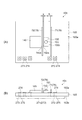
次に、図11を参照して実施形態3に係る生体情報測定機器としての心拍数監視装置1030について説明する。図11は、実施形態3に係る生体情報測定機器としての心拍数監視装置を示す正面図である。なお、実施形態3に係る生体情報測定機器としての心拍数監視装置1030は、図11では図示していないが、前述の実施形態1と同様に、バンドなどの固定部によって、ユーザーの腕に装着される。
(Embodiment 3)
Next, a heart rate monitoring device 1030 as a biological information measuring device according to the third embodiment will be described with reference to FIG. FIG. 11 is a front view showing a heart rate monitoring device as a biological information measuring device according to the third embodiment. Although the heart rate monitoring device 1030 as the biological information measuring device according to the third embodiment is not illustrated in FIG. 11, it is attached to the user's arm by a fixing unit such as a band as in the first embodiment. Is done.

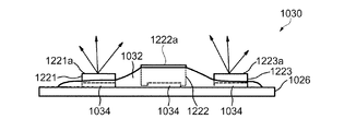
図11に示すように、発光部としての発光素子1221,1223および受光部としての受光素子1222の電気的接続端子1034は、電気的要素の保護のために絶縁性材料(例えばエポキシ樹脂)1032で、好ましくは覆われていなければならない。また、絶縁性材料1032が発光素子1221,1223や受光素子1222を覆わないように構成することができる。具体的には、発光素子1221と受光素子1222との間の領域、発光素子1223と受光素子1222との間の領域を絶縁性材料1032で埋めるように構成することができる。換言すれば、少なくとも受光素子1222の上面1222a、発光素子1221,1223の上面1221a,1223aが絶縁性材料1032に覆われないように構成することができる。このように構成することで、皮膚と発光素子1221,1223との間のエアギャップによる妨害を抑制することができる。さらに、絶縁性材料1032が発光素子1221,1223の上面1221a,1223aや受光素子1222の上面1222aを覆うように構成しても良い。このように構成することで、皮膚と接触する受光素子1222の上面1222aや、発光素子1221,1223の上面1221a,1223aを保護することができるので、受光素子1222の上面1222aや、発光素子1221,1223の上面1221a,1223aの損傷を防ぐことができる。この場合、絶縁性材料1032は保護膜とみなすこともできる。   As shown in FIG. 11, the electrical connection terminals 1034 of the light emitting elements 1221 and 1223 as light emitting parts and the light receiving element 1222 as a light receiving part are made of an insulating material (for example, epoxy resin) 1032 for protection of electrical elements. Should preferably be covered. Further, the insulating material 1032 can be configured not to cover the light emitting elements 1221 and 1223 and the light receiving element 1222. Specifically, a region between the light-emitting element 1221 and the light-receiving element 1222 and a region between the light-emitting element 1223 and the light-receiving element 1222 can be filled with an insulating material 1032. In other words, at least the upper surface 1222a of the light receiving element 1222 and the upper surfaces 1221a and 1223a of the light emitting elements 1221 and 1223 can be configured not to be covered with the insulating material 1032. By comprising in this way, the interference by the air gap between skin and the light emitting elements 1221 and 1223 can be suppressed. Furthermore, the insulating material 1032 may be configured to cover the upper surfaces 1221a and 1223a of the light emitting elements 1221 and 1223 and the upper surface 1222a of the light receiving element 1222. With this configuration, the upper surface 1222a of the light receiving element 1222 that comes into contact with the skin and the upper surfaces 1221a and 1223a of the light emitting elements 1221 and 1223 can be protected, so the upper surface 1222a of the light receiving element 1222 and the light emitting element 1221 Damage to the top surfaces 1221a and 1223a of 1223 can be prevented. In this case, the insulating material 1032 can also be regarded as a protective film.

本実施形態3に係る生体情報測定機器としての心拍数監視装置1030では、一般に可能性がある実施例として、エポキシ樹脂を用いた絶縁性材料1032を設けている。図11においては、絶縁性材料1032は、発光素子1221,1223の上面1221a,1223aを覆うことなく配置され、電気的接続端子1034を保護する。発光素子1221,1223から射出されている光は、矢印にて表される。   In the heart rate monitoring apparatus 1030 as the biological information measuring device according to the third embodiment, an insulating material 1032 using an epoxy resin is provided as a generally possible example. In FIG. 11, the insulating material 1032 is disposed without covering the upper surfaces 1221a and 1223a of the light emitting elements 1221 and 1223, and protects the electrical connection terminal 1034. Light emitted from the light emitting elements 1221 and 1223 is represented by arrows.

このように、絶縁性材料1032の配置は、心拍数監視装置1030の正しい機能を妨げない程度の最小限で行うことにより、発光素子1221,1223および受光素子1222の電気的接続端子1034を保護することで、この心拍数監視装置1030は更に改良されることができる。なお、図示しないが、受光素子1222と発光素子1221との間、および受光素子1222と発光素子1223との間に、上述した実施形態1と同様な第1壁部71、第2壁部72(図5参照)を備えていることがさらに好適である。   In this way, the insulating material 1032 is placed with the minimum amount that does not interfere with the correct function of the heart rate monitoring device 1030, thereby protecting the electrical connection terminals 1034 of the light emitting elements 1221 and 1223 and the light receiving element 1222. Thus, the heart rate monitoring device 1030 can be further improved. Although not shown, between the light receiving element 1222 and the light emitting element 1221 and between the light receiving element 1222 and the light emitting element 1223, the first wall portion 71 and the second wall portion 72 ( It is further preferable that the apparatus is provided.

なお、本実施形態3におけるエポキシ樹脂を注入する構成に変えて、図12に示すような実施形態4に係る生体情報測定機器としての心拍数監視装置1040とすることがさらに好適である。   In addition, it is more preferable to change to the structure which inject | pours the epoxy resin in this Embodiment 3, and to set it as the heart rate monitoring apparatus 1040 as a biological information measuring device which concerns on Embodiment 4 as shown in FIG.

(実施形態4)
次に、実施形態4に係る生体情報測定機器としての心拍数監視装置1040について、図12を参照して説明する。図12は、実施形態4に係る生体情報測定機器としての心拍数監視装置を示す斜視図である。なお、実施形態4に係る生体情報測定機器としての心拍数監視装置1040は、図12では図示していないが、前述の実施形態1と同様に、バンドなどの固定部によって、ユーザーの腕に装着される。
(Embodiment 4)
Next, a heart rate monitoring device 1040 as a biological information measuring device according to the fourth embodiment will be described with reference to FIG. FIG. 12 is a perspective view showing a heart rate monitoring device as a biological information measuring device according to the fourth embodiment. The heart rate monitoring device 1040 as the biological information measuring device according to the fourth embodiment is not shown in FIG. 12, but is attached to the user's arm by a fixing unit such as a band as in the first embodiment. Is done.

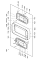
実施形態4に係る生体情報測定機器としての心拍数監視装置1040は、作成されたフレーム1041,1042,1043が配置される。フレーム1041,1042,1043は、発光部としての発光素子1221,1223および受光部としての受光素子1222の周囲に配置され、フレーム1041,1042,1043と、発光素子1221,1223および受光素子1222との間の隙間1036が形成される。そして、フレーム1041,1042,1043をガイドとして絶縁性材料(図12では図示されない)が注入され、発光素子1221,1223および受光素子1222の電気的接続端子1034を覆う。   In the heart rate monitoring device 1040 as the biological information measuring device according to the fourth embodiment, the created frames 1041, 1042, and 1043 are arranged. Frames 1041, 1042, and 1043 are arranged around light emitting elements 1221 and 1223 as light emitting units and light receiving elements 1222 as light receiving units, and frames 1041, 1042, and 1043, light emitting elements 1221 and 1223, and light receiving elements 1222 A gap 1036 is formed between them. Then, an insulating material (not shown in FIG. 12) is injected using the frames 1041, 1042, and 1043 as guides to cover the electrical connection terminals 1034 of the light emitting elements 1221 and 1223 and the light receiving element 1222.

実施形態4に示す例では、発光素子1221,1223および受光素子1222は、個々のフレーム1041,1042,1043によって囲まれる。なお、他の例としては、すべてのフレーム1041,1042,1043は、互いに結合されてもよく、または、すべてのセンサーエレメントは一体のフレームによって囲まれてもよい。なお、フレーム1041,1042,1043を遮光部の一例としての遮光壁として用いることができる。フレーム1041,1042,1043を遮光壁として用いることにより、発光素子1221,1223から射出された光が、直接受光素子1222に入ることを防止することができる。   In the example shown in Embodiment 4, the light emitting elements 1221 and 1223 and the light receiving element 1222 are surrounded by the individual frames 1041, 1042, and 1043. As another example, all the frames 1041, 1042, and 1043 may be coupled to each other, or all the sensor elements may be surrounded by an integral frame. Note that the frames 1041, 1042, and 1043 can be used as light shielding walls as an example of light shielding portions. By using the frames 1041, 1042, and 1043 as light shielding walls, light emitted from the light emitting elements 1221 and 1223 can be prevented from entering the light receiving element 1222 directly.

心拍数監視装置1040の機能に影響を及ぼさないための改善点として、発光素子1221,1223のまわりのフレーム1041,1043の上部エッジ1041a,1043aは、好ましくは発光素子1221,1223の上面1221a,1223aより低いことが好ましい。換言すれば、個別のフレーム1041,1043の上部エッジ1041a,1043aとキャリア1026との距離hFR−LEDは、個別のフレーム1041,1043で囲まれている発光素子1221,1223の上面1221a,1223aとキャリア1026との距離hLEDと、同じか小さい(hFR−LED≦hLED)。
好ましくは、発光素子1221,1223の上面1221a,1223aとキャリア1026との距離hLEDと、フレーム1041,1043の上部エッジ1041a,1043aとキャリア1026との距離hFR−LEDとの差は、0.1mmから0.8mmの範囲に設定する。なお、さらに好ましくは、発光素子1221,1223の上面1221a,1223aとキャリア1026との距離hLEDと、フレーム1041,1043の上部エッジ1041a,1043aとキャリア1026との距離hFR−LEDとの差は、0.2mmから0.5mmの範囲に設定する。
As an improvement in order not to affect the function of the heart rate monitoring device 1040, the upper edges 1041a and 1043a of the frames 1041 and 1043 around the light emitting elements 1221 and 1223 are preferably upper surfaces 1221a and 1223a of the light emitting elements 1221 and 1223, respectively. Lower is preferred. In other words, the distance hFR-LED between the upper edges 1041a and 1043a of the individual frames 1041 and 1043 and the carrier 1026 is equal to the top surfaces 1221a and 1223a of the light emitting elements 1221 and 1223 surrounded by the individual frames 1041 and 1043. The distance hLED to 1026 is the same or smaller (hFR-LED ≦ hLED).
Preferably, the difference between the distance hLED between the upper surfaces 1221a and 1223a of the light emitting elements 1221 and 1223 and the carrier 1026 and the distance hFR-LED between the upper edges 1041a and 1043a of the frames 1041 and 1043 and the carrier 1026 is from 0.1 mm. Set in the range of 0.8 mm. More preferably, the difference between the distance hLED between the upper surfaces 1221a and 1223a of the light emitting elements 1221 and 1223 and the carrier 1026 and the distance hFR-LED between the upper edges 1041a and 1043a of the frames 1041 and 1043 and the carrier 1026 is 0. Set in the range of 2 mm to 0.5 mm.

また、受光素子1222のまわりのフレーム(レシーバーフレーム)1042の上部エッジ1042aは、好ましくは受光素子1222の上面1222aより高いことが好ましい。換言すれば、フレーム1042の上部エッジ1042aとキャリア1026との距離hFR−PDは、フレーム1042で囲まれている受光素子1222の上面1222aとキャリア1026との距離hPDより大きい(hFR−PD>hPD)。
好ましくは、受光素子1222の上面1222aとキャリア1026との距離hPDと、フレーム1042の上部エッジ1042aとキャリア1026との距離hFR−PDの差は、0mmから0.5mmの範囲に設定する。なお、さらに好ましくは、受光素子1222の上面1222aとキャリア1026との距離hPDと、フレーム1042の上部エッジ1042aとキャリア1026との距離hFR−PDの差は、0.1mmから0.2mmの範囲に設定する。
さらに、フレーム1042の上部エッジ1042aとキャリア1026との距離hFR−PDは、発光素子1221,1223の上面1221a,1223aとキャリア1026との距離hLEDよりも大きい(hFR−PD>hLED)。
The upper edge 1042a of the frame (receiver frame) 1042 around the light receiving element 1222 is preferably higher than the upper surface 1222a of the light receiving element 1222. In other words, the distance hFR-PD between the upper edge 1042a of the frame 1042 and the carrier 1026 is larger than the distance hPD between the upper surface 1222a of the light receiving element 1222 surrounded by the frame 1042 and the carrier 1026 (hFR-PD> hPD). .
Preferably, the difference between the distance hPD between the upper surface 1222a of the light receiving element 1222 and the carrier 1026 and the distance hFR-PD between the upper edge 1042a of the frame 1042 and the carrier 1026 is set in the range of 0 mm to 0.5 mm. More preferably, the difference between the distance hPD between the upper surface 1222a of the light receiving element 1222 and the carrier 1026 and the distance hFR-PD between the upper edge 1042a of the frame 1042 and the carrier 1026 is in the range of 0.1 mm to 0.2 mm. Set.
Further, the distance hFR-PD between the upper edge 1042a of the frame 1042 and the carrier 1026 is larger than the distance hLED between the upper surfaces 1221a and 1223a of the light emitting elements 1221 and 1223 and the carrier 1026 (hFR-PD> hLED).

なお、例えば、受光素子1222および発光素子1221,1223が間近である場合、受光素子1222と発光素子1221,1223との間に、1枚のフレーム壁だけが存在する構成であってもよい。これは、製造容易性の理由で発生する場合がある。その1枚のフレーム壁がケースである場合、受光素子1222および発光素子1221,1223で両方のフレームのフレーム壁は一致する。これは、発光素子1221,1223のフレーム壁がより高くなることを意味する、詳述すると、発光素子1221,1223を囲むフレーム1041,1043の内の、受光素子1222がある側のフレーム壁が高くなり、他のフレーム壁は発光素子1221,1223の上面1221a,1223aより低くなる。
さらに、フレーム1041,1042,1043に代えて、受光素子1222と発光素子1221、あるいは発光素子1223との間に第1の壁部を設け、発光素子1221,1223の外側、つまり受光素子1222に対して第1の壁部とは反対側に第2の壁部を設けるように構成しても良い。
このように構成した場合、キャリア1026と第1の壁部の上面との距離は、キャリア1026と第2の壁部の上面との距離よりも大きくなるように構成しても良い。このように構成することで、図13のように発光素子や受光素子を囲うように構成した場合に比べ、より少ない部材でフレームの機能を実現することができる。
For example, when the light receiving element 1222 and the light emitting elements 1221 and 1223 are close to each other, there may be a configuration in which only one frame wall exists between the light receiving element 1222 and the light emitting elements 1221 and 1223. This may occur for reasons of manufacturability. When the single frame wall is a case, the frame walls of both frames coincide with each other in the light receiving element 1222 and the light emitting elements 1221 and 1223. This means that the frame walls of the light emitting elements 1221 and 1223 become higher. Specifically, the frame walls on the side where the light receiving elements 1222 are located in the frames 1041 and 1043 surrounding the light emitting elements 1221 and 1223 are higher. Therefore, the other frame walls are lower than the upper surfaces 1221a and 1223a of the light emitting elements 1221 and 1223.
Further, instead of the frames 1041, 1042, and 1043, a first wall portion is provided between the light receiving element 1222 and the light emitting element 1221 or the light emitting element 1223, and the outside of the light emitting elements 1221 and 1223, that is, with respect to the light receiving element 1222. The second wall portion may be provided on the side opposite to the first wall portion.
When configured in this manner, the distance between the carrier 1026 and the upper surface of the first wall portion may be configured to be larger than the distance between the carrier 1026 and the upper surface of the second wall portion. With this configuration, the function of the frame can be realized with fewer members than in the case where the light emitting element and the light receiving element are surrounded as shown in FIG.

なお、本実施形態4のようにフレーム1041,1043やフレーム1042を用いることにより、注入されるエポキシ樹脂などの絶縁性材料が流れ出すことを防ぐことができる。またこのように、追加構造を作成してエポキシ樹脂などの絶縁性材料を区切ることは、高い量産性を可能にするオプションである。なお、フレーム1041,1043やフレーム1042は、キャリア1026と同じ材料によって構成されても良い。例えばエポキシ系樹脂やポリカーボネイト系樹脂を用いて射出成型でフレームが形成されても良い。   Note that by using the frames 1041, 1043 and the frame 1042 as in the fourth embodiment, it is possible to prevent an insulating material such as an injected epoxy resin from flowing out. In addition, creating an additional structure and separating an insulating material such as an epoxy resin in this way is an option that enables high mass productivity. Note that the frames 1041 and 1043 and the frame 1042 may be made of the same material as the carrier 1026. For example, the frame may be formed by injection molding using an epoxy resin or a polycarbonate resin.

前述したように、絶縁性材料1032(図11参照)は、センサーエレメント(発光素子1221,1223および受光素子1222)の電気的接続端子1034を保護する。しかしながら、これらの電気的接続端子1034は他の要素である追加電子機器(例えばドライバー、検出エレクトロニクス、プロセッサーまたは電源)と、さらに接触しなければならない。そして、キャリア1026(プリント基板(PCB)でもよい)に、これらの追加電子機器とのなんらかの電気接続があることを意味する。また、本実施形態に係る心拍数監視装置の構造は、心拍数のみならず、脈波、脈拍の計測装置にも適用できる。   As described above, the insulating material 1032 (see FIG. 11) protects the electrical connection terminals 1034 of the sensor elements (the light emitting elements 1221 and 1223 and the light receiving element 1222). However, these electrical connection terminals 1034 must make further contact with other components, such as additional electronics (eg, drivers, detection electronics, processors or power supplies). This means that the carrier 1026 (which may be a printed circuit board (PCB)) has some electrical connection with these additional electronic devices. Further, the structure of the heart rate monitoring device according to the present embodiment can be applied not only to the heart rate but also to a pulse wave and pulse measuring device.

(実施形態5)
図13を参照して、実施形態5に係る生体情報測定機器としての心拍数監視装置1050を説明する。図13は、実施形態5に係る生体情報測定機器としての心拍数監視装置を示す断面図である。なお、実施形態5に係る生体情報測定機器としての心拍数監視装置1050は、図13では図示していないが、前述の実施形態1と同様に、バンドなどの固定部によって、ユーザーの腕に装着される。
(Embodiment 5)
With reference to FIG. 13, the heart rate monitoring apparatus 1050 as the biological information measuring device according to the fifth embodiment will be described. FIG. 13 is a cross-sectional view showing a heart rate monitoring device as a biological information measuring device according to the fifth embodiment. The heart rate monitoring apparatus 1050 as the biological information measuring device according to the fifth embodiment is not shown in FIG. 13, but is attached to the user's arm by a fixing unit such as a band as in the first embodiment. Is done.

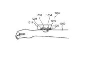
実施形態5に係る生体情報測定機器としての心拍数監視装置1050は、前述した追加電子機器(例えばプロセッサー1052およびドライバー1054)を備えている。外部電気接続端子(図示せず)は、センサーエレメント(発光部としての発光素子1221および受光部としての受光素子1222)と同じキャリア1026に配置されない。つまり、追加電子機器は、センサーエレメントとは別のキャリアあるいは基板に配置されている。このように構成することで、皮膚とセンサーエレメント(発光素子1221および受光素子1222)との良好な接触を維持しつつ、必要な追加電子機器を心拍数監視装置1050に搭載することができる。例えば、外部電気接続端子は、キャリア1026の側面に配置されることができる。   A heart rate monitoring device 1050 as a biological information measuring device according to the fifth embodiment includes the above-described additional electronic devices (for example, a processor 1052 and a driver 1054). External electrical connection terminals (not shown) are not arranged on the same carrier 1026 as the sensor elements (the light emitting element 1221 as the light emitting part and the light receiving element 1222 as the light receiving part). In other words, the additional electronic device is arranged on a carrier or substrate different from the sensor element. With this configuration, necessary additional electronic devices can be mounted on the heart rate monitoring device 1050 while maintaining good contact between the skin and the sensor elements (the light emitting element 1221 and the light receiving element 1222). For example, the external electrical connection terminal can be disposed on the side surface of the carrier 1026.

上述したように、異なる種類のセンサーが、本発明に係る生体情報測定機器において用いられることが可能である。例えば、上述の受光素子1222が電気センサーである場合は、ユーザーの皮膚に接触して、ユーザーの伝導率を測定するための2本の皮膚コンダクタンス電極(例えば、センサーエレメント(図10に示される発光素子1221、受光素子1222))は、皮膚でおおわれる。なお、さらなる、二つ以上の種類のセンサーが、この種の生体情報測定機器において、用いられることが可能である、さらに、センサーエレメントの数は問わない。   As described above, different types of sensors can be used in the biological information measuring device according to the present invention. For example, when the light receiving element 1222 is an electric sensor, two skin conductance electrodes (for example, a sensor element (the light emission shown in FIG. The element 1221 and the light receiving element 1222)) are covered with skin. Further, two or more types of sensors can be used in this type of biological information measuring device, and the number of sensor elements is not limited.

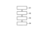
実施形態2〜5において、提唱される生理的パラメーターを測定する生体情報測定機器を製造する方法のフローチャートは、図14において示される。
第1ステップS1において、センサー信号を検出するための少なくとも二つのセンサーエレメント(発光素子1221および受光素子1222)から成るセンサー1022は、キャリア1026上に配置される。第2ステップS2において、上記センサーエレメントの電気的接触をキャリア1026に形成する。第3ステップS3において、一つ以上のフレーム1041,1042は、センサー1022および/または個々のセンサーエレメント(発光素子1221および受光素子1222)周辺で、キャリア1026の上に形成される。第4ステップS4において、キャリア1026に備えられているセンサーエレメント(発光素子1221および受光素子1222)の上面1221a,1222aを覆わない、それぞれのフレーム1041,1042によって囲まれる領域に絶縁性材料1032が注入され満たされる。
In Embodiment 2-5, the flowchart of the method of manufacturing the biometric information measuring device which measures the physiological parameter proposed is shown in FIG.
In the first step S 1, a sensor 1022 including at least two sensor elements (a light emitting element 1221 and a light receiving element 1222) for detecting a sensor signal is disposed on a carrier 1026. In the second step S2, electrical contact of the sensor element is formed on the carrier 1026. In the third step S3, one or more frames 1041, 1042 are formed on the carrier 1026 around the sensor 1022 and / or individual sensor elements (light emitting element 1221 and light receiving element 1222). In the fourth step S4, the insulating material 1032 is injected into regions surrounded by the respective frames 1041 and 1042, which do not cover the upper surfaces 1221a and 1222a of the sensor elements (the light emitting element 1221 and the light receiving element 1222) provided in the carrier 1026. Is satisfied.

上記実施形態2〜5によれば、生体情報測定機器の性能に負の影響を及ぼすことのない電気的接触の保護を成し遂げる方法が提案される。そして、センサーの性能を保つような方法で形成される。例えば、これらのフレーム1041,1043の少なくとも一つは、皮膚に対するセンサーの位置がシフトすることを防ぐ。さらに、これらのフレーム1041,1043の少なくとも一つは、射出された直射的な光が受光素子1222に入射するのを防止するのに役立つことができる。好ましくは、受光素子1222の向きになっている側の、発光素子1221,1223のまわりのフレーム1041,1043の高さは、発光素子1221,1223の上面1221a,1223aの高さより小さくなければならない。加えて、受光素子1222のまわりのフレーム1042は、受光素子1222の上面1222aより高くてもよい。   According to the second to fifth embodiments, a method is proposed that achieves electrical contact protection without negatively affecting the performance of the biological information measuring device. And it forms by the method which maintains the performance of a sensor. For example, at least one of these frames 1041, 1043 prevents the position of the sensor relative to the skin from shifting. Further, at least one of the frames 1041 and 1043 can help prevent the emitted direct light from entering the light receiving element 1222. Preferably, the height of the frames 1041 and 1043 around the light emitting elements 1221 and 1223 on the side facing the light receiving element 1222 should be smaller than the height of the upper surfaces 1221a and 1223a of the light emitting elements 1221 and 1223. In addition, the frame 1042 around the light receiving element 1222 may be higher than the upper surface 1222a of the light receiving element 1222.

上述した実施形態2〜5に係る生体情報測定機器においても、実施形態1で説明した発光部および受光部との間隔の構成を適用することができる。このような構成とすることにより、実施形態1と同様な効果を得ることができる。   The configuration of the interval between the light emitting unit and the light receiving unit described in the first embodiment can also be applied to the biological information measuring devices according to the second to fifth embodiments described above. By adopting such a configuration, the same effect as in the first embodiment can be obtained.

(実施形態6)
上述した実施形態1〜5の生体情報測定機器は、ひずみ計、温度計、体温計、加速度センサー、ジャイロセンサー、圧電センサー、気圧センサー、血圧計、電気化学的センサー、GPS(Global Positioning System)、振動計、等の各種センサーを備えていてもよい。これらのセンサーを備えることで、心拍、脈拍、拍動間の変異、EKG(ElektroKardiogram:心電図)、ECG(Electrocardiogram:心電図)、呼吸数、皮膚温度、体温、体の熱流、電気皮膚反応、GSR(Galvanic skin reflex:皮膚電気反射)、EMG(Electromyogram:筋電図)、EEG(electroencephalogram:脳電図)、EOG(Electrooculography:眼球電図)、血圧、体脂肪、水分補給レベル、活動レベル、体動、酸素消費量、グルコース、血糖値、筋肉量、筋肉にかかる圧力、骨にかかる圧力、紫外線吸収、睡眠状態、体調、ストレス状態、体位(例えば、横臥、直立、座位、等)等の、1または1以上の生理学的パラメーターを示すデータに基づいて、個人の生理学的状態に関する情報を導出することができる。また、これらの各種センサーによって得られた値を、例えば、スマートフォン、携帯電話機、フィーチャーフォン等の携帯型通信端末やコンピューターやタブレット型コンピューター等の情報処理端末に送信して、携帯型通信端末や情報処理端末にて生理学的パラメーターの演算処理を実行してもよい。
(Embodiment 6)
The biological information measuring devices of Embodiments 1 to 5 described above are strain gauges, thermometers, thermometers, acceleration sensors, gyro sensors, piezoelectric sensors, barometric pressure sensors, blood pressure meters, electrochemical sensors, GPS (Global Positioning System), vibrations. Various sensors such as a meter may be provided. With these sensors, heart rate, pulse, rhythm variation, EKG (ElektroKardiogram), ECG (Electrocardiogram), respiratory rate, skin temperature, body temperature, body heat flow, electric skin reaction, GSR ( Galvanic skin reflex: electromyogram, EMG (electromyogram), EEG (electroencephalogram), EOG (electrooculography), blood pressure, body fat, hydration level, activity level, body movement , Oxygen consumption, glucose, blood sugar level, muscle mass, muscle pressure, bone pressure, ultraviolet absorption, sleep state, physical condition, stress state, body position (eg, lying, standing, sitting, etc.) Alternatively, information about an individual's physiological state can be derived based on data indicative of one or more physiological parameters. Also, the values obtained by these various sensors are transmitted to portable communication terminals such as smartphones, mobile phones, feature phones, and information processing terminals such as computers and tablet computers, for example, You may perform the calculation process of a physiological parameter in a processing terminal.

ユーザーは、生体情報を測定する前に、生体情報測定機器、携帯型通信端末、もしくは情報処理端末にユーザー自身のプロフィールを入力する。これによりユーザーは、そのプロフィールと生体情報測定結果とに基づき、推奨される健康なライフスタイルを確立し維持する可能性を最大にするために、対処が必要となるユーザーの特異な特性情報、環境情報の提供を受けることができる。提供される情報としては、運動種別、運動強度、運動時間、等のような運動情報、食事時間、食事の量、推奨される摂取食材や摂取メニュー、避けるべき摂取食材や摂取メニュー、等のような食事情報、睡眠時間、睡眠の深さ、睡眠の質、起床時間、着床時間、就労時間、ストレス情報、消費カロリー、摂取カロリー、カロリー収支、等のような生活支援情報、基礎代謝、体脂肪量、体脂肪率、筋肉量、等のような身体情報、投薬情報、サプリメント摂取情報、医療情報、等の一つもしくは複数が挙げられる。   Before measuring the biological information, the user inputs his / her profile to the biological information measuring device, the portable communication terminal, or the information processing terminal. This allows the user to take into account the user's unique characteristic information and environment that needs to be addressed to maximize the likelihood of establishing and maintaining a recommended healthy lifestyle based on their profile and biometric measurements. Information can be provided. Information provided includes exercise information such as exercise type, exercise intensity, exercise time, etc., meal time, amount of meal, recommended intake ingredients and intake menu, intake intake ingredients and intake menu to be avoided, etc. Dietary information, sleep time, sleep depth, sleep quality, wake-up time, landing time, working time, stress information, calorie consumption, calorie intake, calorie balance, etc., basic metabolism, body One or more of physical information such as fat mass, body fat percentage, muscle mass, etc., medication information, supplement intake information, medical information, etc. may be mentioned.

事前に入力するユーザー自身のプロフィールとしては、例えば、年齢、生年月日、性別、趣味、職種、血液型、過去のスポーツ歴、活動レベル、食事、睡眠の規則性、排便習慣の規則性、状況適応性、持続性、応答性、反応の強さ、性質等のユーザーの性格、ユーザーの自主独立レベル、自立形成、自己管理、社交性、記憶力および学問的成就能力、ユーザーの覚醒レベル、認知速度、注意力疎外要因の回避能力、覚醒状態および自己監督能力を含むユーザーの注意力、注意持続能力、体重、身長、血圧、ユーザーの健康状態、医者による診察結果、医者による診察日、医者や健康管理者との接触の有無、現在服用中の薬剤およびサプリメント、アレルギーの有無、アレルギー歴、現在のアレルギー症状、健康に関連する挙動の所見、ユーザーの病気歴、ユーザーの手術歴、家族歴、個人による調整を必要とした離婚または失業のような社会的事象、ユーザーの健康優先度に関する所信、価値観、振舞いを変える能力、生活のストレス原因と考えられる事象、ストレス管理方法、ユーザーの自己意識度、ユーザーの感情移入度、ユーザーの権限委譲度、ユーザーの自尊心、ユーザーの運動、睡眠状態、弛緩状態、毎日の活動の現在のルーチン、ユーザーの生活における重要な人物(例えば、配偶者、友人、同僚または上司)の性格、重要な人物の関係において健康なライフスタイルを阻害するまたはストレスに寄与する衝突が存在するか否かについてのユーザーの受け止め方、等の一つもしくは複数が挙げられる。   The user's own profile to be entered in advance includes, for example, age, date of birth, gender, hobby, occupation, blood type, past sports history, activity level, meal, regularity of sleep, regularity of defecation habits, status User characteristics such as adaptability, persistence, responsiveness, strength of response, nature, user self-independence level, self-reliance, self-management, sociality, memory and academic fulfillment ability, user arousal level, cognitive speed , Ability to avoid attention alienation factors, user attention, including wakefulness and self-supervision ability, attention continuation ability, weight, height, blood pressure, user health, doctor checkup results, doctor checkup date, doctor and health Presence or absence of contact with the administrator, drugs and supplements currently taken, presence or absence of allergies, history of allergies, current allergic symptoms, findings of health related behaviors, users History of illness, user's surgery history, family history, social events such as divorce or unemployment that require individual adjustments, user's health priorities, values, ability to change behavior, causes of life stress Possible events, stress management methods, user self-awareness, user empathy, user authority delegation, user self-esteem, user exercise, sleep state, relaxation state, daily routine of daily activities, user's User perceptions of the character of an important person in life (eg, spouse, friend, colleague or boss), whether there are conflicts that interfere with a healthy lifestyle or contribute to stress in the relationship of the important person One or more of the above and the like.

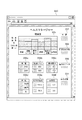
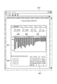
ここで、推奨される健康的なライフスタイルを確立し維持する可能性を最大にするために、対処が必要となるユーザーの特異な特性情報、環境情報の提供を受けることができる実施形態6に係る生体情報測定機器について、図15〜図21を用いて説明する。図15は、実施形態6の生体情報測定機器におけるヘルスマネージャーの起点となるウェブページの概略を示す図である。図16は、栄養ウェブページの一例を示す図であり、図17は、活動レベルウェブページの一例を示す図である。また、図18は、精神集中ウェブページの一例を示す図であり、図19は、睡眠ウェブページの一例を示す図である。また、図20は、毎日の活動ウェブページの一例を示す図であり、図21は、健康度ウェブページの一例を示す図である。   Here, in order to maximize the possibility of establishing and maintaining a recommended healthy lifestyle, it is possible to receive specific characteristic information and environmental information of a user who needs to take action in Embodiment 6. Such a biological information measuring device will be described with reference to FIGS. FIG. 15 is a diagram illustrating an outline of a web page serving as a starting point of a health manager in the biological information measuring device according to the sixth embodiment. FIG. 16 is a diagram illustrating an example of a nutrition web page, and FIG. 17 is a diagram illustrating an example of an activity level web page. FIG. 18 is a diagram illustrating an example of a mental concentration web page, and FIG. 19 is a diagram illustrating an example of a sleep web page. FIG. 20 is a diagram illustrating an example of a daily activity web page, and FIG. 21 is a diagram illustrating an example of a health level web page.

実施形態6に係る生体情報測定機器は、図示しないが、例えばマイクロプロセッサーに接続されたセンサー装置を備えている。そして、実施形態6に係る生体情報測定機器では、最終的にモニターユニットへ送られて保存される種々の生活活動に関するデータや、モニターユニットにより維持されるウェブサイトからユーザーによって入力される個人データもしくは生活情報が、マイクロプロセッサーによって処理され、生体情報として提供される。以下に、具体的な一例を示し説明する。   Although not illustrated, the biological information measuring device according to the sixth embodiment includes a sensor device connected to, for example, a microprocessor. In the biological information measuring device according to the sixth embodiment, data on various life activities that are finally sent to the monitor unit and stored, personal data input by the user from a website maintained by the monitor unit, or Life information is processed by a microprocessor and provided as biological information. Hereinafter, a specific example will be described and described.

ユーザーは、ウェブページ、アプリケーションソフト、その他の通信媒体を介して、そのユーザーのためのヘルスマネージャーにアクセスする。図15は、一例として、ヘルスマネージャーの起点となるウェブページ550を示す。図15に示すヘルスマネージャーのウェブページ550では、多様なデータをユーザーへ提供する。このようにして提供されるデータは、例えば、(1)種々のセンサー装置が測定した値に基づく種々の生理学的パラメーターを示すデータ、(2)種々の生理学的パラメーターを示すデータから導出されるデータ、(3)センサー装置により発生される種々のコンテキストパラメーターを示すデータおよびユーザーが入力するデータのうちの、1つまたはそれ以上である。   A user accesses a health manager for the user via a web page, application software, or other communication medium. FIG. 15 shows, as an example, a web page 550 that is the starting point of the health manager. The health manager web page 550 shown in FIG. 15 provides various data to the user. The data provided in this way includes, for example, (1) data indicating various physiological parameters based on values measured by various sensor devices, and (2) data derived from data indicating various physiological parameters. (3) one or more of data indicating various context parameters generated by the sensor device and data entered by the user.

分析状態データは、(1)センサー装置が取得する種々の生理学的パラメーターを示すデータ、(2)種々の生理学的パラメーターから導出されるデータ、(3)センサー装置が取得する種々のコンテキストパラメーターを示すデータおよびユーザーが入力するデータのうちの1つまたはそれ以上を計算により求める健康度、(4)壮健度およびライフスタイル指数などに変換するために、ある特定のユーティリティーまたはアルゴリズムを利用する点に特徴がある。例えば、摂取した食料に関連してユーザーが入力するデータに基づきカロリー、たんぱく質、脂肪、炭水化物およびある特定のビタミンの量のようなものを計算することができる。また、別の例として、皮膚温度、心拍数、呼吸数、熱流および/またはGSRを用いることにより、所望の時間にわたるストレスレベルの指数をユーザーに提供することができる。さらに別の例として、皮膚温度、熱流、拍動間変異、心拍数、脈拍、呼吸数、中心部体温、電気皮膚反応、EMG、EEG、EOG、血圧、酸素消費量、周囲の音および加速度計のような装置で検出される体の動きを用いることにより、所望の時間にわたる睡眠パターンの指数をユーザーに提供することができる。   The analysis state data indicates (1) data indicating various physiological parameters acquired by the sensor device, (2) data derived from various physiological parameters, and (3) various context parameters acquired by the sensor device. Characterized by the use of certain utilities or algorithms to convert one or more of the data and data entered by the user into calculated health, (4) health and lifestyle index, etc. There is. For example, things such as the amount of calories, protein, fat, carbohydrates and certain vitamins can be calculated based on data entered by the user in relation to the food consumed. As another example, skin temperature, heart rate, respiration rate, heat flow and / or GSR can be used to provide the user with an index of stress level over a desired time. As yet another example, skin temperature, heat flow, beat-to-beat variation, heart rate, pulse, respiratory rate, core body temperature, electrical skin reaction, EMG, EEG, EOG, blood pressure, oxygen consumption, ambient sound and accelerometer By using body movements detected by such devices, it is possible to provide the user with an index of sleep patterns over a desired time.

図15に示すウェブページ550には、健康度としての健康指標555が表示されている。この健康指標555は、ユーザーの成績および推奨される健康な日課を達成した度合いを測定し、それらをメンバーユーザーにフィードバックするためのグラフィックなユーティリティーである。このように、健康指標555は、メンバーユーザーに対して彼らの健康状態や健康維持に関する行動の進捗状況を示す。健康指標555は、ユーザーの健康およびライフスタイルに関する6つのカテゴリー、即ち、栄養、活動レベル、精神集中、睡眠、毎日の活動、および元気度(総合的な所感)を含む。「栄養」のカテゴリーは、その人(ユーザー)が何を、いつ、そしてどのくらい食べて飲んだかの情報に関する。「活動レベル」のカテゴリーは、その人がどのくらい動き回るかの運動量に関する。「精神集中」のカテゴリーは、その人(ユーザー)の精神が高度に集中した状態で弛緩状態となるための活動の質(能力)、およびその人がその活動に集中する時間に関する。「睡眠」のカテゴリーは、その人(ユーザー)の睡眠の質、および量に関する。「毎日の活動」のカテゴリーは、その人(ユーザー)が毎日行わなければならないこと、およびその人が遭遇する健康リスクに関する。「元気度(所感)」のカテゴリーは、ある特定の日について気分がよいか否かの一般的な受け止め方に関する。各カテゴリーには、好ましくは、「悪い」から「よい」の間で変化するスケールで、ユーザーがそのカテゴリーに関してどのような実績をあげたかを示すレベル表示または棒グラフを備えている。   A web page 550 shown in FIG. 15 displays a health index 555 as a health level. This health index 555 is a graphical utility for measuring user performance and the degree of achievement of recommended healthy daily routines and feeding them back to member users. As described above, the health index 555 indicates the progress of actions related to the health status and health maintenance of the member users. The health index 555 includes six categories related to the user's health and lifestyle: nutrition, activity level, mental concentration, sleep, daily activity, and spirit (total feeling). The category of “nutrition” relates to information on what, when and how much the person (user) eats and drinks. The “activity level” category relates to the amount of exercise that the person moves around. The category of “Mental Concentration” relates to the quality of the activity (ability) for the person (user) to become relaxed when the spirit of the person (user) is highly concentrated, and the time for which the person concentrates on the activity. The category of “sleep” relates to the sleep quality and quantity of the person (user). The “Daily Activity” category relates to what the person (user) has to do every day and the health risks the person encounters. The category of “Energetic (feelings)” relates to the general perception of whether or not you feel good about a particular day. Each category is preferably provided with a level display or bar graph showing what the user has achieved for that category on a scale that varies from “bad” to “good”.

各メンバーユーザーが上述した最初の調査を終了すると、ユーザーに対して、自身の特性、および生活環境の要約を提供するプロフィールが作成され、推奨される健康的な日課および/または目標が提示される。推奨される健康的な日課には、適当な栄養、運動、精神集中、およびユーザーの毎日の活動(生活)に関する特定のアドバイス、における任意の組み合わせが含まれる。これら推奨される健康的な日課に係る活動をユーザーの生活に如何に取り込むかのガイドとして、模範的なスケジュールなどを提示してもよい。ユーザーはその調査を定期的に受け、その結果に基づき、上述したような項目をそれに応じて実践する。   When each member user completes the initial survey described above, a profile is created that provides the user with a summary of their characteristics and living environment, and recommended healthy daily routines and / or goals are presented . Recommended healthy routines include any combination of appropriate nutrition, exercise, mental concentration, and specific advice on the user's daily activities (life). An exemplary schedule or the like may be presented as a guide on how to incorporate these recommended healthy daily activities into the user's life. The user regularly receives the survey and, based on the results, implements the items described above accordingly.

「栄養」のカテゴリーは、ユーザーが入力するデータと、センサー装置が感知するデータとの両方から計算される。ユーザーが入力するデータには、朝食、昼食、夕食、および任意のおやつの時刻や飲食時間と、飲食する食料、ビタミンのようなサプリメントおよび予め選択した時間の間に飲む水や他の液体(飲料水や液体状の食料)とが含まれる。このデータや種々の食料の公知の特性に関する蓄積されたデータに基づき、中央モニターユニットは、消費カロリー、またはたんぱく質、脂肪、炭水化物、ビタミンなどの含有量のような、よく知られた栄養学的な値を計算する。   The “nutrition” category is calculated from both data entered by the user and data sensed by the sensor device. Data entered by the user includes the time and eating time for breakfast, lunch, dinner, and any snack, as well as food and vitamin supplements and water and other liquids (drinks) that are consumed during a preselected time. Water and liquid food). Based on this data and the accumulated data on the known properties of various foods, the central monitoring unit is able to use well-known nutritional variables such as calories burned or content of proteins, fats, carbohydrates, vitamins, etc. Calculate the value.

「栄養」のカテゴリーにおいては、健康指標555の栄養を示す棒グラフに基づいて、推奨される健康的な日課に関して決定することができる。この推奨される健康的な日課は、ユーザーの性別、年齢、身長/体重のような情報に基づき調整することができる。なお、毎日摂取するカロリーやたんぱく質、繊維、脂肪、炭水化物などの栄養素や水の量、および全体の摂取量に対する割合に関するある特定の栄養の目標を、ユーザー、またはユーザーに代わって代理者が設定することができる。棒グラフの計算に用いるパラメーターには、1日の食事回数、水の消費量、毎日食べる食物の種類、および量をユーザーが入力したものが含まれる。   In the “Nutrition” category, decisions can be made regarding recommended healthy daily routines based on the bar graph showing nutrition of the health index 555. This recommended healthy daily routine can be adjusted based on information such as the user's gender, age, height / weight. In addition, you or your agent set specific nutritional goals for the amount of nutrients and water, such as calories, protein, fiber, fat, and carbohydrates you consume every day, and the percentage of your total intake. be able to. Parameters used to calculate the bar graph include the number of meals per day, water consumption, the type of food eaten daily, and the amount entered by the user.

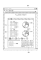
栄養学的情報は、図16に示すような栄養ウェブページ560によりユーザーに提示される。栄養ウェブページ560は、栄養の実際および目標となる数値をそれぞれ円グラフで示す栄養数値チャート565,570と、実際の栄養摂取総量および目標となる栄養摂取総量をそれぞれ示す栄養摂取チャート575,580を含むことが好ましい。栄養数値チャート565,570は、炭水化物、たんぱく質および脂肪のような項目を百分比で示すのが好ましく、栄養摂取チャート575,580は、カロリーの合計値および目標値を、脂肪、炭水化物、たんぱく質およびビタミンのような成分で分けて示すのが好ましい。ウェブページ560は、食物および水を消費した時間を示す履歴585、ユーザーが栄養に関連するニュース記事、栄養に関する日課を改善するためのアドバイス、およびネットワーク上のどこかの関連の広告を直接チェックできるようにするハイパーリンク590、および適用期間などを選択可能なカレンダー595も含む。ハイパーリンク590で示す項目は、調査により個人について知り得た情報、および健康指標により測定された個人の成績に基づいて選択することができる。   Nutritional information is presented to the user via a nutrition web page 560 as shown in FIG. Nutrition web page 560 includes nutrition value charts 565 and 570 showing the actual and target values of nutrition in a pie chart, and nutrition intake charts 575 and 580 showing the actual total amount of nutrient intake and the target total nutrient intake, respectively. It is preferable to include. Nutrition numerical charts 565, 570 preferably show percentages such as carbohydrates, proteins and fats, and nutrition intake charts 575, 580 show total calorie values and target values for fats, carbohydrates, proteins and vitamins. It is preferable to show the components separately. Web page 560 can directly check history 585 showing time spent on food and water, news articles related to nutrition, advice on improving nutritional routines, and relevant advertisements anywhere on the network A hyperlink 590 to be made and a calendar 595 capable of selecting an application period and the like are also included. The item indicated by the hyperlink 590 can be selected based on information obtained from the survey about the individual and the individual's performance measured by the health index.

健康指標555の「活動レベル」のカテゴリーは、その日にユーザーが、いつ、どのように活動したか(動いたか)などに関するユーザーのチェックを、支援するように設計されており、ユーザーが入力するデータと、センサー装置が感知するデータとの両方を利用する。ユーザーが入力するデータには、例えば、ユーザーが午前8時から午後5時まで机に向かって仕事をした後、午後6時から午後7時までエアロビクス講習を受けるというようなユーザーの毎日の活動に関する詳細事項が含まれる。センサー装置により感知される関連のデータには、心拍数、加速度計のような装置により感知される運動、熱流、呼吸数、消費カロリー量、GSR、および水分補給レベルが含まれ、これらはセンサー装置または中央モニターユニットにより取り出すことができる。消費カロリー量は、ユーザーが入力する運動の種類とユーザーが入力する運動の持続時間との掛け算、感知する運動と運動の時間およびフィルター定数との掛け算、または感知される熱流と時間とフィルター定数との掛け算のような種々の方法で計算することができる。   The “activity level” category of the health index 555 is designed to support the user's check on when and how (actually) the user acted on that day. And data sensed by the sensor device are used. The data entered by the user is related to the user's daily activities, for example, the user works from 8 am to 5 pm at the desk and then takes an aerobics course from 6 pm to 7 pm Details are included. Relevant data sensed by the sensor device includes heart rate, motion sensed by devices such as accelerometers, heat flow, respiratory rate, calories burned, GSR, and hydration levels, which are sensor devices. Or it can be taken out by the central monitor unit. Calorie consumption is calculated by multiplying the type of exercise entered by the user with the duration of the exercise entered by the user, multiplying the sensed exercise with the duration of exercise and the filter constant, or the detected heat flow, time and filter constant. It can be calculated by various methods such as multiplication of

「活動レベル」のカテゴリーでは、健康指標555の活動レベルを示す棒グラフに基づいて、推奨される健康的な日課に関して決定することができる。この推奨される健康的な日課は、活動において消費される最小目標カロリーなどである。なお、最小目標カロリーは、ユーザーの性別、年齢、身長、体重のような情報に基づき設定可能である。棒グラフの計算に用いるパラメーターには、各種の運動または精力的なライフスタイル活動に費やす時間であって、ユーザーが入力したものおよび/またはセンサー装置が感知したものや予め計算したエネルギー消費パラメーター以上に燃焼したカロリー数が含まれる。   In the “activity level” category, a recommended healthy daily routine can be determined based on a bar graph showing the activity level of the health index 555. This recommended healthy daily routine is the minimum target calorie consumed in the activity. The minimum target calorie can be set based on information such as the user's sex, age, height, and weight. The parameters used to calculate the bar graph are the time spent on various exercise or energetic lifestyle activities, burning more than what the user entered and / or what the sensor device sensed or pre-calculated energy consumption parameters Contains the number of calories burned.

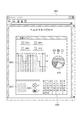
個人ユーザーの活動(動き)に関する情報は、図17に示す活動レベルウェブページ600によりユーザーに提示される。この活動レベルウェブページ600は、ユーザーの活動を3つのカテゴリー、即ち、所定の単位時間に関して「高」、「中」、「低」でモニターする棒グラフの形をした活動度グラフ605を含む。円グラフの形の活動百分比チャート610は、ユーザーが各カテゴリーで費やした、例えば1日のような所定の期間の百分比を示すために提示することができる。また、活動レベルウェブページ600は、燃焼カロリー総量、毎日の燃焼カロリー目標値、カロリー摂取合計値、およびエアロビクス運動時間のような項目を表示するためのカロリー表示(図示せず)を設けることもできる。活動レベルウェブページ600は、ユーザーが、関連のニュース記事、活動レベルに関する日課を改善するためのアドバイス、およびネットワーク上の関連広告を直接チェックできるようにするため、少なくとも1つのハイパーリンク620を含む。   Information on the activity (movement) of the individual user is presented to the user through an activity level web page 600 shown in FIG. The activity level web page 600 includes an activity graph 605 in the form of a bar graph that monitors user activity in three categories: “high”, “medium”, and “low” for a given unit time. An activity percentage chart 610 in the form of a pie chart can be presented to show the percentage of a predetermined period, such as one day, that a user has spent in each category. The activity level web page 600 may also provide a calorie display (not shown) for displaying items such as total calorie burn, daily calorie target value, total calorie intake, and aerobics exercise time. . Activity level web page 600 includes at least one hyperlink 620 to allow the user to directly check for related news articles, advice on improving daily activity levels, and related advertisements on the network.

活動レベルウェブページ600は種々のフォーマットで見ることができるが、棒グラフ、円グラフ、およびその両方のようなグラフまたはチャートをユーザーが選択可能とすることができ、活動レベルチェックボックス625により選択可能である。活動レベルカレンダー630は、適用期間などを選択できるようにするために提供される。ハイパーリンク620に示す項目は、調査によりその個人から抽出した情報および健康指標により測定される成績に基づき選択することができる。   Activity level web page 600 can be viewed in a variety of formats, but a graph or chart such as a bar graph, pie chart, and both can be selected by the user and can be selected by an activity level check box 625. is there. The activity level calendar 630 is provided so that an application period or the like can be selected. The item shown in the hyperlink 620 can be selected based on the information extracted from the individual through the survey and the results measured by the health index.

健康指標555の「精神集中」のカテゴリーは、ユーザーが、精神を集中しながら深い弛緩状態に体が到達できるようにする活動を行う時間に関するパラメーターを、モニターすることを支援するように設計されており、ユーザーが入力するデータとセンサー装置が感知するデータとの両方に基づくものである。詳説すると、ユーザーはヨガまたは瞑想のような弛緩活動の開始時間および終了時間を入力することができる。精神集中の深さにより決まるこれらの活動の品質は、センサー装置により感知される皮膚温度、心拍数、呼吸数および熱流を含むパラメーターをモニターすることにより測定可能である。センサー装置または中央モニターユニットの何れかにより得られるGSRの百分比変化を利用することもできる。   The “Mental Concentration” category of health index 555 is designed to help users monitor parameters related to time spent performing activities that allow the body to reach deep relaxation while concentrating on the spirit. And based on both data input by the user and data sensed by the sensor device. Specifically, the user can enter the start and end times of relaxation activities such as yoga or meditation. The quality of these activities, as determined by the depth of mental concentration, can be measured by monitoring parameters including skin temperature, heart rate, respiratory rate and heat flow as sensed by the sensor device. It is also possible to take advantage of the percentage change in GSR obtained by either the sensor device or the central monitor unit.

「精神集中」のカテゴリーにおいては、健康指標555の精神集中の活動レベルを示す棒グラフに基づいて、推奨される健康的な日課に関して決定することができる。この推奨される健康的な日課は、精神を高度に集中した状態にしながら体を深く弛緩させる活動への毎日の参加が含まれて表示される。この棒グラフの計算に使用するパラメーターには、精神集中活動に費やす時間の長さ、および精神集中活動の深さ、または品質を示すベースラインからの、センサー装置により感知される皮膚温度、心拍数、呼吸数、熱流またはGSRの百分比変化が含まれる。   In the “Mental Concentration” category, a recommendation can be made regarding a recommended healthy routine based on a bar graph showing the level of mental concentration activity of the health index 555. This recommended healthy daily routine includes daily participation in activities that deeply relax the body while keeping the mind highly focused. The parameters used to calculate this bar graph include the length of time spent on mental concentration activity, and the skin temperature, heart rate perceived by the sensor device, from the baseline indicating the depth or quality of the mental concentration activity, This includes percentage change in respiratory rate, heat flow or GSR.

深く自己を顧みる行動(内省)、および体を深く弛緩させるなどの精神集中活動のために費やす時間に関する情報は、図18に示す精神集中ウェブページ650によりユーザーに提示される。なお、精神集中活動は、セッションと呼ばれることがある。精神集中ウェブページ650は、セッションに費やした時間655、目標時間660、精神集中の深さの目標値および実際の値を示す比較部分665、皮膚温度、心拍数、呼吸数、熱流および/またはGSRのようなものから導出される全体的なストレスレベルを示すヒストグラム670を含む。   Information regarding deeply self-respecting behavior (introspection) and time spent for mental concentration activities such as deep relaxation of the body is presented to the user via the mental concentration web page 650 shown in FIG. In addition, mental concentration activity is sometimes called a session. The mental concentration web page 650 includes a time 655 spent in the session, a target time 660, a comparison portion 665 showing the target value and actual value of the depth of mental concentration, skin temperature, heart rate, respiratory rate, heat flow and / or GSR. Histogram 670 showing the overall stress level derived from

比較部分665では、目標となる精神集中状態を示す人間の輪郭は実線で示され、実際の精神集中状態を示す人間の輪郭は、精神集中のレベルに応じてぼやけた状態(図18では破線で表す)と実線の間で変化する。また、好ましい精神集中ウェブページ650は、ユーザーが関連のニュース記事、精神集中に関する日課の改善に関するアドバイス、およびネットワーク上の関連広告を直接チェックできるようにするハイパーリンク680、精神集中に関する日課の改善に関するアドバイスおよび関連の広告と、適用期間を選択可能にするカレンダー685とを含む。ハイパーリンク680で示す項目は、調査により個人から知り得た情報および健康指標により測定される成績に基づき選択することができる。   In the comparison portion 665, the human outline indicating the target mental concentration state is indicated by a solid line, and the human outline indicating the actual mental concentration state is blurred according to the level of mental concentration (in FIG. 18, it is indicated by a broken line). And the solid line. The preferred mental concentration web page 650 also includes hyperlinks 680 that allow users to directly check related news articles, advice on improving mental concentration, and related advertisements on the network, related to improving daily concentration on mental concentration. Includes advice and related advertisements, and a calendar 685 that allows the application period to be selected. The item indicated by the hyperlink 680 can be selected based on the information obtained from the individual through the survey and the results measured by the health index.

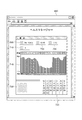
健康指標555の「睡眠」のカテゴリーは、ユーザーが睡眠パターンおよび睡眠の質をモニターすることを支援できるように設計されている。このカテゴリーは、ユーザーが健康なライフスタイルにおける睡眠の重要性と、体の機能の毎日の通常の変化である日周期に対する睡眠の関係と、についての学習を助けるように意図されている。「睡眠」のカテゴリーは、ユーザーが入力するデータとセンサー装置が感知するデータとの両方に基づくものである。関連の各時間インターバルの間にユーザーが入力するデータには、ユーザーの入眠時刻と起床時刻(睡眠時間)および睡眠の質のランクが含まれる。センサー装置から得られる関連性のあるデータには、皮膚温度(体温)、熱流、拍動間変異、心拍数、脈拍数、呼吸数、中心部体温、電気皮膚反応、EMG、EEG、EOG、血圧および酸素消費量が含まれる。また、周囲の音および加速度計のような装置により検知される体の動きも関連性を有する。その後、このデータを用いて、入眠時刻および起床時刻、睡眠中断および睡眠の質、および睡眠の深さなどについて計算し導出することができる。   The “sleep” category of health index 555 is designed to help users monitor sleep patterns and sleep quality. This category is intended to help users learn about the importance of sleep in a healthy lifestyle and the relationship of sleep to the circadian cycle, which is a normal daily change in body function. The “sleep” category is based on both data entered by the user and data sensed by the sensor device. Data entered by the user during each relevant time interval includes the user's sleep time and wake-up time (sleep time) and sleep quality rank. Relevant data obtained from sensor devices include skin temperature (body temperature), heat flow, beat-to-beat variation, heart rate, pulse rate, respiratory rate, core body temperature, electrical skin reaction, EMG, EEG, EOG, blood pressure And oxygen consumption. Also relevant are body sounds detected by ambient sounds and devices such as accelerometers. The data can then be used to calculate and derive sleep time and wake time, sleep interruption and sleep quality, sleep depth, and the like.

健康指標555の睡眠を示す棒グラフは、毎晩の好ましい最小睡眠時間の確保、予測可能な就寝時刻、および起床時刻を含む健康な日課について表示される。この棒グラフの計算を可能にする特定のパラメーターには、センサー装置により感知されるかユーザーが入力する毎日の睡眠時刻および起床時刻と、ユーザーが等級をつけるかまたは他のデータから導出される睡眠の質が含まれる。   A bar graph showing sleep for the health index 555 is displayed for a healthy daily routine that includes ensuring a preferred minimum sleep time every night, a predictable bedtime, and a wake-up time. Specific parameters that allow the calculation of this bar graph include daily sleep and wake-up times that are sensed by the sensor device or entered by the user, and sleep that is graded by the user or derived from other data. Quality is included.

睡眠に関する情報は、図19に示す睡眠ウェブページ690によりユーザーに提示される。睡眠ウェブページ690は、センサー装置からのデータまたはユーザーが入力するデータの何れかに基づく睡眠時間表示695と、ユーザーの就寝時刻表示700、および起床時刻表示705を含む。なお、ユーザーにより入力される睡眠の質について、睡眠の質ランク710を利用し表示することも可能である。また、1日の時間インターバルを超える表示を睡眠ウェブページ690において行う場合、睡眠時間表示695は累計値として表示し、就寝時刻表示700、起床時刻表示705、および睡眠の質ランク710は平均値として計算し、表示することができる。また、睡眠ウェブページ690は、所定の時間インターバルにわたって1つの睡眠関連パラメーターを計算し表示するユーザーにより選択可能な睡眠グラフ715も含む。図19は、1日にわたる熱流(体温)の変化を示すが、この熱流は、睡眠中は低く、起きている時は高くなる傾向がある。この情報から、その人のバイオリズムを得ることが可能である。   Information related to sleep is presented to the user by a sleep web page 690 shown in FIG. The sleep web page 690 includes a sleep time display 695 based on either data from the sensor device or data input by the user, a user bedtime display 700, and a wake-up time display 705. Note that the quality of sleep input by the user can be displayed using the sleep quality rank 710. When the display exceeding the time interval of the day is performed on the sleep web page 690, the sleep time display 695 is displayed as a cumulative value, the bedtime display 700, the wake-up time display 705, and the sleep quality rank 710 are average values. Can be calculated and displayed. Sleep web page 690 also includes a sleep graph 715 that can be selected by the user to calculate and display one sleep-related parameter over a predetermined time interval. FIG. 19 shows the change in heat flow (body temperature) over the day, but this heat flow tends to be low during sleep and high when waking up. From this information, the person's biorhythm can be obtained.

また、睡眠グラフ715は、体の動きをモニターするセンサー装置に組み込んだ加速度計からのデータをグラフ表示する。また、睡眠ウェブページ690は、ユーザーが睡眠に関連するニュース記事、睡眠に関する日課を改善するためのアドバイス、およびネットワーク上にある関連の広告を直接チェックできるようにするハイパーリンク720と、関連の時間インターバルを選択するための睡眠カレンダー725とを含むことができる。ハイパーリンク720で示す項目は、調査において個人から知り得た情報、および健康指標により測定される成績に基づき特別に選択することができる。   The sleep graph 715 displays data from an accelerometer incorporated in a sensor device that monitors body movement in a graph. The sleep web page 690 also includes a hyperlink 720 that allows the user to directly check sleep related news articles, advice on improving sleep routines, and related advertisements on the network and associated time. And a sleep calendar 725 for selecting an interval. The item indicated by the hyperlink 720 can be specially selected based on the information obtained from the individual in the survey and the results measured by the health index.

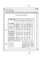
健康指標555の「毎日の活動」のカテゴリーは、健康や安全に関連するある特定の活動、およびリスクをユーザーがモニターすることを支援できるように設計されており、すべてユーザーにより入力されるデータに基づくものである。毎日の生活の活動に関する「毎日の活動」のカテゴリーは、下位概念の4つのカテゴリーが挙げられる。具体的には、(1)歯ブラシまたはフロスを用いる歯の手入れやシャワーを浴びるような活動をユーザーがモニターするのを可能にする個人的衛生に係る項目、(2)ユーザーが処方箋通りの薬またはサプリメントを飲んでいるか否かを追跡し、煙草またはアルコールの消費量などをユーザーがモニターするのを可能にする健康維持に係る項目、(3)家族または友人と共に過ごす時間やレジャーおよび精神集中活動をユーザーがモニターするのを可能にする個人的時間に係る項目、(4)家庭の雑用のような仕事および家計活動をユーザーがモニターするのを可能にする責任に係る項目、に分けられる。   The “Daily Activity” category of Health Indicator 555 is designed to help users monitor certain activities and risks related to health and safety, all of which are entered by the user. Is based. There are four categories of sub-concepts in the category of “daily activities” relating to activities of daily living. Specifically, (1) items related to personal hygiene that allow users to monitor activities such as taking care of teeth or taking showers using a toothbrush or floss; (2) Keep track of whether you are taking supplements and allow health monitoring items to allow users to monitor tobacco or alcohol consumption, and (3) spend time, leisure and mental concentration activities with family or friends It can be divided into items related to personal time that allow the user to monitor, and (4) items related to responsibility that allow the user to monitor work and household activities such as household chores.

「毎日の活動」のカテゴリーにおいて、健康指標555の「毎日の活動」を示す棒グラフは、以下に述べる推奨される健康的な日課について表示することが好ましい。個人の衛生に関する日課の一例としては、ユーザーが毎日シャワーを浴びるか入浴し、毎日ブラシとフロスを用いて歯を清潔に保ち、規則的な便通を維持することが望ましい。また、健康維持に関する日課の一例としては、ユーザーが薬、ビタミン剤および/またはサプリメントを飲み、禁煙し、節酒し、健康マネージャーにより毎日、健康をモニターすることが望ましい。個人的時間に関する日課の一例としては、ユーザーが毎日少なくとも所定時間は家族と過ごす時間を創出し、および/または友人と良質な時間を過ごし、仕事を行う時間を減らし、レジャーまたは遊びの時間を取り入れ、頭を使う活動を行うことが望ましい。責任に関する日課の一例としては、ユーザーが家の雑事を行い、仕事に遅れず、約束を守ることが望ましい。棒グラフは、ユーザーが入力する情報により決定される、および/またはユーザーが毎日リストアップされた活動を完了する度合いに基づき計算される。   In the “daily activity” category, the bar graph indicating “daily activity” of the health index 555 is preferably displayed for the recommended healthy daily routine described below. As an example of a daily routine for personal hygiene, it is desirable for users to take a shower or bath every day, keep their teeth clean with a brush and floss every day, and maintain regular bowel movements. In addition, as an example of a daily routine related to health maintenance, it is desirable for a user to take drugs, vitamins and / or supplements, quit smoking, save alcohol, and monitor health daily by a health manager. An example of a personal time routine is to create time for the user to spend at least a predetermined time each day with their family and / or spend good quality time with friends, reduce work time, and incorporate leisure or play time It is desirable to conduct activities that use the head. As an example of the daily routine regarding responsibility, it is desirable that the user does miscellaneous things at home and keeps his promises without being late for work. The bar graph is determined based on information entered by the user and / or based on the degree to which the user completes the activities listed daily.

これらの活動に関する情報は、図20に示す毎日の活動ウェブページ730によりユーザーに提示される。毎日の活動ウェブページ730における活動チャート735は、ユーザーがその日課により必要とされることを実行したか否かを示す。活動チャート735は、下位概念のうちの1つまたはそれ以上について選択可能である。活動チャート735では、色または影がついたボックスは、必要とされる活動をユーザーが実行したことを示し、色または影のないボックスは、その活動をユーザーが実行していないことを示している。活動チャート735は、選択可能な時間インターバルにおいて作成し、見ることが可能である。図20は、特定の週における個人的衛生および個人的時間のカテゴリーを一例として示している。さらに、毎日の活動ウェブページ730は、ユーザーが関連のあるニュース記事、毎日の生活の活動に関する日課を改善するためのアドバイス、およびネットワーク上の関連の広告を直接チェックできるようにするハイパーリンク740と、関連の時間インターバルを選択するための毎日の活動のカレンダー745とを含むことができる。ハイパーリンク740に示す項目は、調査において個人から知り得た情報、および健康指標により決定される成績に基づき選択することができる。   Information about these activities is presented to the user via the daily activity web page 730 shown in FIG. The activity chart 735 on the daily activity web page 730 indicates whether the user has performed what is required by the daily routine. The activity chart 735 can be selected for one or more of the sub-concepts. In activity chart 735, a box with a color or shadow indicates that the user has performed the required activity, and a box without a color or shadow indicates that the user has not performed the activity. . Activity chart 735 can be created and viewed at selectable time intervals. FIG. 20 shows an example of personal hygiene and personal time categories for a particular week. In addition, the daily activity web page 730 includes hyperlinks 740 that allow the user to directly check for relevant news articles, advice on improving daily activities on daily activities, and related advertisements on the network. , And a daily activity calendar 745 for selecting relevant time intervals. The item shown in the hyperlink 740 can be selected based on information obtained from the individual in the survey and results determined by the health index.

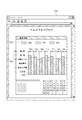
健康指標555の「元気度」のカテゴリーは、特定の日に元気であったか否かの認識をユーザーがモニターするのを可能にするように設計され、ユーザーが直接入力する本質的に主観的な等級情報に基づくものである。ユーザーは、以下の9つの領域、即ち、(1)精神的鋭敏さ、(2)精神的および心理的幸福度、(3)エネルギーレベル、(4)人生のストレスへの対処能力、(5)対面を重んじる度合い、(6)物理的幸福度、(7)自己抑制、(8)動機、(9)他人との関係による慰め、に関して、好ましくは1から5までのスケールを用いてランク付けを行う。これらの度合い(等級)を平均して、健康指標555の棒グラフの計算に使用する。   The “Energy” category of the health index 555 is designed to allow the user to monitor the perception of whether or not he / she was active on a particular day, and is essentially a subjective grade that the user inputs directly It is based on information. Users are divided into the following nine areas: (1) Mental acuity, (2) Mental and psychological well-being, (3) Energy level, (4) Ability to cope with stress in life, (5) Rank with respect to the degree of respect for face-to-face, (6) physical well-being, (7) self-restraint, (8) motivation, and (9) comfort in relation to others, preferably using a scale from 1 to 5 Do. These degrees (grades) are averaged and used to calculate the health indicator 555 bar graph.

図21は、元気度のウェブページ750を示す。元気度のウェブページ750は、連続または不連続の任意の日にちを含む、ユーザーが選択可能な時間インターバルにわたる元気度を、ユーザーがチェックできるようにする。なお、図21で示す例では、元気度を健康指数として表示している。元気度のウェブページ750では、元気度の選択ボックス760を用いることにより、ユーザーは、1つのカテゴリーについて元気度の棒グラフ755をチェックする選択を行うか、または2つのカテゴリー、またはそれ以上のカテゴリーについて元気度の棒グラフ755を並べて比較することができる。例えば、ユーザーは、前月と比べて総合的な睡眠の等級が改善されたか否かをチェックするために、睡眠の棒グラフだけを作動状態にしたい場合があるあるいは、睡眠と活動レベルとを同時に表示することにより、睡眠の等級とそれに対応する活動レベルの等級とを比較評価して、それぞれの日にちの間に何らかの相関関係が存在するか否かをチェックする場合がある。所定の時間インターバルについて栄養の等級と元気度の等級とを表示して、毎日の食事習慣とそのインターバルの間の食事習慣と元気度との間に何らかの相関関係が存在するか否かをチェックする場合がある。図21は、説明のための一例として、6月8日から6月14日の週の睡眠と活動レベルの棒グラフによる比較を示す。また、元気度のウェブページ750は、ユーザーがログインしてヘルスマネージャーを利用した日数の合計、ユーザーが入会以来ヘルスマネージャーを利用した日にちの割合、およびユーザーがデータを収集するためにセンサー装置を利用した時間の割合のようなアクセス情報、および統計を表示する追跡計算器765も含む。   FIG. 21 shows an energetic web page 750. The spirit web page 750 allows the user to check the spirit over a user selectable time interval, including any continuous or discontinuous date. In the example shown in FIG. 21, the energy level is displayed as a health index. In the Genkiness web page 750, the Genkiness selection box 760 allows the user to make a selection to check the Genki bar graph 755 for one category, or for two categories or more. The bar graph 755 of the spirit can be compared side by side. For example, the user may want to activate only the sleep bar graph to see if the overall sleep grade has improved compared to the previous month, or display sleep and activity levels simultaneously. Thus, the sleep grade and the corresponding activity level grade may be compared and evaluated to check whether there is any correlation between the dates. Display nutritional and spiritual grades for a given time interval to check whether there is any correlation between daily dietary habits and dietary habits and spirituality during that interval There is a case. FIG. 21 shows a bar graph comparison of sleep and activity levels during the week of June 8 to June 14 as an example for illustration. The Genkiness web page 750 also shows the total number of days the user has logged in and used the health manager, the percentage of days the user has used the health manager since joining, and the user uses the sensor device to collect data Also included is a tracking calculator 765 that displays access information, such as the percentage of time spent, and statistics.

図15に示すヘルスマネージャーの起点となるウェブページ550の一例は、それぞれが健康度としての健康指標555のカテゴリーに対応するユーザーにより選択可能な複数のカテゴリーの要約556aないし556fを含む。各カテゴリーの要約556aないし556fは、対応するカテゴリーに関して予め選択しフィルターをかけたデータの副集合を提示する。栄養カテゴリーの要約556aは、カロリー摂取量の毎日の目標値と実際値とを示す。活動レベルカテゴリーの要約556bは、燃焼カロリー量の毎日の目標値と実際値とを示す。精神集中の要約556cは、精神集中の深さの目標値および実際値を示す。睡眠カテゴリーの要約556dは、目標の睡眠時間、実際の睡眠時間、および睡眠の質の等級を示す。毎日の活動カテゴリーの要約556eは、推奨される健康的な日課(毎日の活動)に対する完了した活動の割合に基づく目標点数および実際点数を表示する。元気度のカテゴリーの要約556fは、その日の健康度の目標および実際の等級を示す。   An example of the web page 550 that is the starting point of the health manager shown in FIG. 15 includes a plurality of category summaries 556a to 556f that can be selected by the user, each corresponding to the category of the health index 555 as the health level. Each category summary 556a-556f presents a subset of pre-selected and filtered data for the corresponding category. The nutrition category summary 556a shows the daily target and actual values of caloric intake. The activity level category summary 556b shows the daily target value and the actual value of the calorie content. The mental concentration summary 556c shows a target value and an actual value of the depth of the mental concentration. The sleep category summary 556d shows the target sleep time, actual sleep time, and sleep quality grade. Daily activity category summary 556e displays target and actual scores based on the ratio of completed activities to recommended healthy daily routines (daily activities). The spirit category summary 556f shows the goal and actual grade of the day's health.

また、ウェブページ550は、ニュース記事へのハイパーリンク(不図示)、最初の調査によりチェックされる栄養不良のような傾向に基づくユーザーへのコメント(不図示)、および合図(不図示)を含むこともできる。情報を毎日ユーザーに提供する毎日の日課部分557を含むこともできる。毎日の日課部分557のコメントとしては、例えば、毎日必要となる水の摂取量や、それを可能とする具体的手段のアドバイスなどを表示することができる。また、ウェブページ550は、健康指標555の各カテゴリーにおけるユーザーの成績を積極的に評価して改善のためのアドバイスを提示する問題解決セクション558を含むことができる。例えば、システムによりユーザーの睡眠レベルが「低」で、ユーザーが不眠症であることを示唆する場合、問題解決セクション558は睡眠を改善するための方法をアドバイスすることができる。また、問題解決セクション558は、成績の改善に関するユーザーの質問を含むことができる。また、ウェブページ550は、入力ダイアログボックスを立ち上げる毎日のデータセクション559を含むことができる。入力ダイアログボックスにより、ユーザーはヘルスマネージャーにより必要とされる種々のデータの入力を容易に行うことができる。当該技術分野において知られているように、データの入力は予め提示されたリストまたは普通の自由テキスト形式の入力かの選択が可能である。また、ウェブページ550は、ユーザーの身長、体重、体の測定値、BMI、および心拍数、血圧または任意の生理学的パラメーターのような生命兆候に関する情報を与える体の状態セクション561を含むことができる。   Web page 550 also includes hyperlinks (not shown) to news articles, comments to users based on trends such as malnutrition checked by the initial survey (not shown), and cues (not shown). You can also. A daily routine portion 557 that provides information to the user daily may also be included. As a comment of the daily routine portion 557, for example, an intake amount of water that is necessary every day, advice on a specific means that enables it, and the like can be displayed. The web page 550 may also include a problem solving section 558 that actively evaluates the user's performance in each category of the health index 555 and provides advice for improvement. For example, if the system indicates that the user's sleep level is “low” and the user is insomnia, the problem resolution section 558 can advise on ways to improve sleep. The problem solving section 558 can also include user questions regarding performance improvements. Web page 550 can also include a daily data section 559 that launches an input dialog box. The input dialog box allows the user to easily input various data required by the health manager. As is known in the art, the input of data can be selected from a pre-presented list or normal free text input. Web page 550 can also include a body condition section 561 that provides information about the user's height, weight, body measurements, BMI, and vital signs such as heart rate, blood pressure, or any physiological parameter. .

(受光部の変形例)
ここで、上述した実施形態1に係る受光部140の変形例について、図22を参照して説明する。図22は、受光部の変形例を示す部分断面図である。図22に示すように、基板160(センサー基板)に実装されている受光部140は、半導体の基板141に形成されたPN接合のダイオード素子142などにより実現できる。この場合に、受光角度を絞るための角度制限フィルターや受光素子に入射する光の波長を制限する波長制限フィルター(光学フィルター膜)148を、このダイオード素子142上に形成してもよい。なお、波長制限フィルター(光学フィルター膜)148は、例えばダイオード素子142側から第1酸化膜143、第1窒化膜144、第2酸化膜145、および第2窒化膜146の順に形成された構成とすることができる。なお、本受光部の変形例は、上述した実施形態のいずれにおいても適用可能である。
(Modification of light receiving part)
Here, a modified example of the light receiving unit 140 according to the first embodiment will be described with reference to FIG. FIG. 22 is a partial cross-sectional view showing a modification of the light receiving unit. As shown in FIG. 22, the light receiving unit 140 mounted on the substrate 160 (sensor substrate) can be realized by a PN junction diode element 142 formed on the semiconductor substrate 141. In this case, an angle limiting filter for narrowing the light receiving angle and a wavelength limiting filter (optical filter film) 148 for limiting the wavelength of light incident on the light receiving element may be formed on the diode element 142. The wavelength limiting filter (optical filter film) 148 has a configuration in which, for example, a first oxide film 143, a first nitride film 144, a second oxide film 145, and a second nitride film 146 are formed in this order from the diode element 142 side. can do. In addition, the modification of this light-receiving part is applicable in any of embodiment mentioned above.

このような構成とすることにより、より少ない領域に波長制限フィルター(光学フィルター膜)148を設けることができ、より小型の生体情報測定モジュールおよび生体情報測定機器を提供することが可能となる。   By adopting such a configuration, the wavelength limiting filter (optical filter film) 148 can be provided in a smaller area, and a smaller biological information measuring module and biological information measuring device can be provided.

(発光部の変形例)
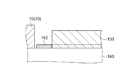
次に、上述した実施形態1に係る発光部150の変形例について、図23を参照して説明する。図23は、発光部の変形例を示す部分断面図である。図23に示すように、基板160(センサー基板)に実装されている発光部150の周囲には、壁部としてのフレーム70(図5に示す第1凸部79)と、発光部150から周囲方向に射出された光を反射する反射機能層152とが設けられている。なお、反射機能層152は、基板160の上面側から見た平面視で、発光部150の周囲を全周に亘って囲むように設けられていてもよいし、発光部150の周囲の少なくとも一部に設けられていてもよい。なお、本受光部の変形例は、上述した実施形態のいずれにおいても適用可能である。
(Modification of light emitting part)
Next, a modification of the light emitting unit 150 according to Embodiment 1 described above will be described with reference to FIG. FIG. 23 is a partial cross-sectional view showing a modification of the light emitting unit. As shown in FIG. 23, around the light emitting unit 150 mounted on the substrate 160 (sensor substrate), there are a frame 70 (first convex portion 79 shown in FIG. 5) as a wall and the periphery from the light emitting unit 150. A reflective functional layer 152 that reflects light emitted in the direction is provided. Note that the reflective functional layer 152 may be provided so as to surround the entire periphery of the light emitting unit 150 in a plan view as viewed from the upper surface side of the substrate 160, or at least one of the periphery of the light emitting unit 150. It may be provided in the part. In addition, the modification of this light-receiving part is applicable in any of embodiment mentioned above.

このような構成とすることにより、発光部150の周囲方向に射出された光を、反射機能層152によって反射し、測定対象物に向かう光とすることができる。これにより、測定対象物に向かう光の強度(発光強度)を高めることができ、生体情報の測定精度を向上させるとともに安定化させることが可能となる。   With such a configuration, the light emitted in the peripheral direction of the light emitting unit 150 can be reflected by the reflective functional layer 152 to be directed toward the measurement object. Thereby, the intensity | strength (light emission intensity) of the light which goes to a measurement object can be raised, and it becomes possible to improve while stabilizing the measurement accuracy of biological information.

なお、以上のように実施形態について詳細に説明したが、本発明の新規事項および効果から実体的に逸脱しない多くの変形が可能であることは当業者には容易に理解できるであろう。従って、このような変形例はすべて本発明の範囲に含まれるものとする。例えば、明細書又は図面において、少なくとも一度、より広義または同義な異なる用語と共に記載された用語は、明細書又は図面のいかなる箇所においても、その異なる用語に置き換えることができる。また生体情報測定モジュール、光検出ユニット、生体情報測定機器等の構成、動作も本実施形態で説明したものに限定されず、種々の変形実施が可能である。   Although the embodiment has been described in detail as described above, it will be easily understood by those skilled in the art that many modifications can be made without departing from the novel matters and effects of the present invention. Accordingly, all such modifications are intended to be included in the scope of the present invention. For example, a term described at least once together with a different term having a broader meaning or the same meaning in the specification or the drawings can be replaced with the different term in any part of the specification or the drawings. Further, the configuration and operation of the biological information measurement module, the light detection unit, the biological information measurement device, and the like are not limited to those described in the present embodiment, and various modifications can be made.

10…バンド部、12…バンド穴、14…バックル部、15…バンド挿入部、16…突起部、30…ケース部、32…発光窓部、34…トップケース、35…端子部、36…ボトムケース、40,40a,40b,40c…生体情報測定モジュールとしてのセンサー部、50…透光部材、52…凸部、53,55…Oリング、54…溝部、56…凹部、57,59…外周溝部、58…押圧抑制部、70…フレーム、71…第1壁部、72…第2壁部、72b…壁部の頂面、78…第2凸部、79…第1凸部、80(80a,80b)…絞り部、140…受光部、140a…受光部の外周、150,154…発光部、150a,154a…第1側面、150b,154b…第2側面、150c,154c…発光部の外周、151,153…ドーム型レンズ、152…反射機能層、160…支持部としての基板、160a…支持面(表面)、160b…裏面、170…体動センサー部、172…加速度センサー、180…振動発生部、200…処理部、210…信号処理部、212…体動ノイズ低減部、220…拍動情報演算部、230…報知制御部、240…記憶部、250…通信部、252…アンテナ、260…報知部、270…制御部、271…ベース部としての回路基板、272…回路素子、273…スルーホール、274…第1接続端子、275…第2接続端子、280…遮光層、281…導電層としての金属層、282…絶縁層、400…生体情報測定機器、410…手首、411…対象物としての皮膚、420…端末装置、430…表示部、a…第1凸部と発光部との間の距離、b…第2凸部と発光部との間の距離、h1…第1凸部の高さ、h2…第2凸部の高さ、h3…受光部の高さ。   DESCRIPTION OF SYMBOLS 10 ... Band part, 12 ... Band hole, 14 ... Buckle part, 15 ... Band insertion part, 16 ... Projection part, 30 ... Case part, 32 ... Light emission window part, 34 ... Top case, 35 ... Terminal part, 36 ... Bottom Case, 40, 40a, 40b, 40c ... sensor part as biological information measuring module, 50 ... translucent member, 52 ... convex part, 53,55 ... O-ring, 54 ... groove part, 56 ... concave part, 57,59 ... outer periphery Groove portion, 58 ... Pressing suppression portion, 70 ... Frame, 71 ... First wall portion, 72 ... Second wall portion, 72b ... Top surface of the wall portion, 78 ... Second convex portion, 79 ... First convex portion, 80 ( 80a, 80b) ... diaphragm part, 140 ... light receiving part, 140a ... outer periphery of light receiving part, 150, 154 ... light emitting part, 150a, 154a ... first side face, 150b, 154b ... second side face, 150c, 154c ... light emitting part Outer circumference, 151, 153 ... Do Mold lens, 152 ... Reflective function layer, 160 ... Substrate as support part, 160a ... Support surface (front surface), 160b ... Back face, 170 ... Body motion sensor part, 172 ... Acceleration sensor, 180 ... Vibration generating part, 200 ... Processing 210, signal processing unit, 212, body motion noise reduction unit, 220 ... pulsation information calculation unit, 230 ... notification control unit, 240 ... storage unit, 250 ... communication unit, 252 ... antenna, 260 ... notification unit, 270 ... Control part, 271 ... Circuit board as base part, 272 ... Circuit element, 273 ... Through hole, 274 ... First connection terminal, 275 ... Second connection terminal, 280 ... Light shielding layer, 281 ... Metal layer as conductive layer , 282 ... Insulating layer, 400 ... Biological information measuring device, 410 ... Wrist, 411 ... Skin as an object, 420 ... Terminal device, 430 ... Display part, a ... Between the first convex part and the light emitting part Distance, b ... distance between the second projecting portion and the light emitting portion, h1 ... first convex portion of the height, h2 ... second convex portion of the height, h3 ... height of the light receiving portion.

Claims (11)

対象物に対して光を射出する発光部と、
前記対象物を経由した光を受光する受光部と、
支持面を有し、前記支持面上に前記発光部および前記受光部を支持する支持部と、
前記支持面に配置され、少なくとも一部が前記発光部と前記受光部との間に配置された第1凸部と、
前記支持面に配置され、前記発光部に対して前記第1凸部と反対側に配置された第2凸部と、を備え、
前記第1凸部の前記支持面からの高さは、前記第2凸部の前記支持面からの高さよりも高いことを特徴とする生体情報測定モジュール。
A light emitting unit that emits light to an object;
A light receiving unit that receives light via the object;
A support portion having a support surface and supporting the light emitting portion and the light receiving portion on the support surface;
A first convex portion disposed on the support surface, at least a portion of the first convex portion being disposed between the light emitting portion and the light receiving portion;
A second convex portion disposed on the support surface and disposed on the opposite side of the first convex portion with respect to the light emitting portion,
The biological information measuring module, wherein a height of the first convex portion from the support surface is higher than a height of the second convex portion from the support surface.
前記第1凸部および前記第2凸部は、前記支持部と一体であることを特徴とする請求項1に記載の生体情報測定モジュール。   The biological information measurement module according to claim 1, wherein the first convex portion and the second convex portion are integrated with the support portion. 前記第1凸部は、前記受光部の周囲を囲むように配置されていることを特徴とする請求項1または請求項2に記載の生体情報測定モジュール。   The biological information measurement module according to claim 1, wherein the first convex portion is disposed so as to surround the periphery of the light receiving portion. 前記支持面から前記第1凸部の頂面までの高さは、前記支持面から前記受光部の頂面までの高さより高いことを特徴とする請求項3に記載の生体情報測定モジュール。   The biological information measurement module according to claim 3, wherein a height from the support surface to a top surface of the first convex portion is higher than a height from the support surface to the top surface of the light receiving unit. 前記第1凸部と前記第2凸部との間に前記発光部が配置され、前記発光部の周囲の少なくとも一部には、前記発光部から射出された光を反射する反射機能層が設けられていることを特徴とする請求項1ないし請求項4のいずれか一項に記載の生体情報測定モジュール。   The light emitting portion is disposed between the first convex portion and the second convex portion, and a reflective functional layer that reflects light emitted from the light emitting portion is provided at least around the light emitting portion. The biological information measuring module according to claim 1, wherein the biological information measuring module is provided. 前記第1凸部と前記発光部の前記受光部側の第1側面との間の距離aは、前記第2凸部と前記第1側面と反対側の前記発光部の第2側面との間の距離bよりも小さいことを特徴とする請求項1ないし請求項5のいずれか一項に記載の生体情報測定モジュール。   A distance a between the first convex portion and the first side surface of the light emitting portion on the light receiving portion side is between the second convex portion and the second side surface of the light emitting portion opposite to the first side surface. The biological information measuring module according to claim 1, wherein the biological information measuring module is smaller than a distance b. 回路基板を備え、
前記支持部は、前記回路基板と、前記発光部および前記受光部の少なくとも一方とを電気的に接続する導通部を備えていることを特徴とする請求項1ないし請求項6のいずれか一項に記載の生体情報測定モジュール。
With a circuit board,
The said support part is provided with the conduction | electrical_connection part which electrically connects the said circuit board and at least one of the said light emission part and the said light-receiving part, The any one of Claim 1 thru | or 6 characterized by the above-mentioned. The biological information measurement module according to 1.
前記支持部、前記第1凸部および前記第2凸部は、波長が495nm〜570nmの光を遮光することを特徴とする請求項1ないし請求項7のいずれか一項に記載の生体情報測定モジュール。   The biological information measurement according to any one of claims 1 to 7, wherein the support portion, the first convex portion, and the second convex portion shield light having a wavelength of 495 nm to 570 nm. module. 前記支持部は、前記支持面に沿って設けられている遮光層を備えていることを特徴とする請求項1ないし請求項8のいずれか一項に記載の生体情報測定モジュール。   The biological information measurement module according to any one of claims 1 to 8, wherein the support portion includes a light shielding layer provided along the support surface. 前記遮光層は、絶縁層および導電層を含むことを特徴とする請求項9に記載の生体情報測定モジュール。   The biological information measuring module according to claim 9, wherein the light shielding layer includes an insulating layer and a conductive layer. 請求項1ないし請求項10のいずれか一項に記載の生体情報測定モジュールが搭載されていることを特徴とする生体情報測定機器。   A biological information measuring device on which the biological information measuring module according to any one of claims 1 to 10 is mounted.
JP2015000116A 2015-01-05 2015-01-05 Biological information measurement module, and biological information measurement device Pending JP2016123717A (en)

Priority Applications (1)

Application Number Priority Date Filing Date Title
JP2015000116A JP2016123717A (en) 2015-01-05 2015-01-05 Biological information measurement module, and biological information measurement device

Applications Claiming Priority (1)

Application Number Priority Date Filing Date Title
JP2015000116A JP2016123717A (en) 2015-01-05 2015-01-05 Biological information measurement module, and biological information measurement device

Publications (1)

Publication Number Publication Date
JP2016123717A true JP2016123717A (en) 2016-07-11

Family

ID=56357226

Family Applications (1)

Application Number Title Priority Date Filing Date
JP2015000116A Pending JP2016123717A (en) 2015-01-05 2015-01-05 Biological information measurement module, and biological information measurement device

Country Status (1)

Country Link
JP (1) JP2016123717A (en)

Cited By (4)

* Cited by examiner, † Cited by third party
Publication number Priority date Publication date Assignee Title
WO2018032454A1 (en) * 2016-08-18 2018-02-22 深圳市柔宇科技有限公司 Wearable device and control method
CN109833033A (en) * 2017-11-24 2019-06-04 精工电子有限公司 Bioinformation detecting device
JP2019111193A (en) * 2017-12-25 2019-07-11 セイコーエプソン株式会社 Biological information measuring device and biological information detection sensor
JP2020199044A (en) * 2019-06-09 2020-12-17 廉士 澤田 Biological sensor

Cited By (6)

* Cited by examiner, † Cited by third party
Publication number Priority date Publication date Assignee Title
WO2018032454A1 (en) * 2016-08-18 2018-02-22 深圳市柔宇科技有限公司 Wearable device and control method
CN109833033A (en) * 2017-11-24 2019-06-04 精工电子有限公司 Bioinformation detecting device
JP2019092910A (en) * 2017-11-24 2019-06-20 セイコーインスツル株式会社 Biological information detector
JP2019111193A (en) * 2017-12-25 2019-07-11 セイコーエプソン株式会社 Biological information measuring device and biological information detection sensor
JP2020199044A (en) * 2019-06-09 2020-12-17 廉士 澤田 Biological sensor
JP7264462B2 (en) 2019-06-09 2023-04-25 廉士 澤田 biosensor

Similar Documents

Publication Publication Date Title
JP5817943B1 (en) Biological information measuring module and biological information measuring device
US9808198B2 (en) Biological information measuring device
JP6609932B2 (en) Biological information measuring device
US20160198966A1 (en) Biological information measuring module, biological information measuring apparatus, light detecting apparatus, light detecting module, and electronic apparatus
US20160242659A1 (en) Pulse-wave measuring module, biological-information measuring module, and electronic device
JP2016140641A (en) Biological information measuring apparatus
JP2016123713A (en) Biological information measurement module, and biological information measurement device
JP2016123715A (en) Biological information measurement module, and biological information measurement device
JP2016123714A (en) Biological information measurement module, and biological information measurement device
ES2253393T3 (en) SYSTEM TO CONTROL HEALTH, WELFARE AND EXERCISE.
JP2016144560A (en) Wearable device, biological information measurement device, biological information measurement system, and biological information measurement device charging method
JP6056946B2 (en) Biological information measuring module and biological information measuring device
US20140275813A1 (en) Wearable body monitor device with a flexible section and sensor therein
US20170112391A1 (en) Apparatus for detecting human physiological and contextual information
JP2016131604A (en) Biological information measurement system, biological information measurement device, and biological information measurement method
JP5880747B1 (en) Pulse wave measurement module and electronic device
JP2016123717A (en) Biological information measurement module, and biological information measurement device
JP6128241B2 (en) Pulse wave measurement module and electronic device
JP2017140439A (en) Pulse wave measuring module and electronic device
JP5850190B1 (en) Biological information measuring module and biological information measuring device
JP2016158701A (en) Biological information measurement module and biological information measurement apparatus
JP2016179124A (en) Biological information measuring device
JP6365644B2 (en) Biological information measuring device
JP2016165331A (en) Biological information measurement module, and biological information measuring apparatus
JP2016123846A (en) Biological information measurement sensor, and biological information measurement device