JP2016120802A - Substantially egg-shaped upper part body of automobile car body formed with transparent thermoplastic resin composition - Google Patents
Substantially egg-shaped upper part body of automobile car body formed with transparent thermoplastic resin composition Download PDFInfo
- Publication number
- JP2016120802A JP2016120802A JP2014261279A JP2014261279A JP2016120802A JP 2016120802 A JP2016120802 A JP 2016120802A JP 2014261279 A JP2014261279 A JP 2014261279A JP 2014261279 A JP2014261279 A JP 2014261279A JP 2016120802 A JP2016120802 A JP 2016120802A
- Authority
- JP
- Japan
- Prior art keywords
- upper body
- apex
- resin composition
- egg
- rear end
- Prior art date
- Legal status (The legal status is an assumption and is not a legal conclusion. Google has not performed a legal analysis and makes no representation as to the accuracy of the status listed.)
- Granted
Links
Images


Landscapes
- Body Structure For Vehicles (AREA)
- Polyesters Or Polycarbonates (AREA)
Abstract
Description
本発明は、透明な熱可塑性樹脂組成物により形成された自動車車体の略卵型上部ボデーに関するものであって、特に、超小型電気自動車等の超小型モビリティの車体に適した、軽量で、製造が簡単で、運転者が周囲の状況を的確に視認・把握でき、搭乗者が周囲の景色を全面的に歪みなく見通すことができ、必要とされる剛性を備えた自動車車体の上部ボデーである。 The present invention relates to an approximately egg-shaped upper body of an automobile body formed of a transparent thermoplastic resin composition, and is particularly lightweight and manufactured suitable for an automobile body of ultra-compact mobility such as an ultra-compact electric vehicle. It is an upper body of an automobile body that is easy to drive, allows the driver to accurately see and grasp the surrounding situation, and allows the passenger to see the surrounding scenery completely without distortion, and has the required rigidity. .
近年、超小型電気自動車等のいわゆる超小型モビリティの開発及び普及が図られている。 In recent years, so-called ultra-small mobility such as micro-electric vehicles has been developed and spread.
これは、省エネ・CO2削減が求められるとともに、高齢化、過疎化、地方の公共交通機関の廃止等が進行している状況において、小さな動力で駆動でき、年配者にも運転しやすく、低価格で提供できる超小型モビリティが新たな交通手段として期待されているためである。例えば、このような超小型モビリティとして、1人乗り超小型電気自動車である「コムス」がトヨタ車体株式会社から販売されている。 This is because energy saving and CO 2 reduction are required, and in a situation where aging, depopulation, and abolition of local public transportation are advancing, it can be driven with small power and is easy to drive for the elderly. This is because ultra-compact mobility that can be offered at a price is expected as a new means of transportation. For example, as such ultra-compact mobility, “COMS”, a single-seater ultra-compact electric vehicle, is sold by Toyota Auto Body Co., Ltd.
本発明は、特に、超小型電気自動車等の超小型モビリティに適した、軽量で、製造が簡単で、搭乗者が周囲の状況・景色を全面的に歪みなく見通すことができ、必要とされる剛性を備えた自動車車体の上部ボデーを提供するものである。 The present invention is particularly suitable for ultra-compact mobility such as ultra-compact electric vehicles, is lightweight, easy to manufacture, and allows passengers to see the surrounding situation and scenery completely without distortion. An upper body of a car body having rigidity is provided.
車体の軽量化等を目的として、車体を合成樹脂で形成することは、特許文献1〜2に開示されるように、従来から行われている。
For the purpose of reducing the weight of the vehicle body, forming the vehicle body from a synthetic resin has been conventionally performed as disclosed in
特許文献1には、1〜2人乗用の小型車両の車体として、FRP等の繊維強化合成樹脂材により一体成形された上部車体半部を用い、この上部車体半部をフランジで下部車体半部と一体に接合したものが開示されている。
In
また、特許文献2には、合成樹脂で作成したアッパボデー・インナ、アッパボデー・アウタ、フ―ド、前バンパ、後バンパ、ルーフ等の部材を接着して組立てた車体の上部ボデーが開示されている。
しかしながら、特許文献1の上部車体半部は、FRP等の繊維強化合成樹脂材で形成されたものであって、搭乗者が周囲の状況・景色を全面的に歪みなく見通せるような透明なものではない。また、特許文献2の上部ボデーは、複数の部材を組立てるものであって、製造が簡単ではなく、搭乗者が周囲の状況・景色を全面的に歪みなく見通せるような透明なものでもない。
However, the upper vehicle body half of
さらに、超小型自動車の上部ボデーを略卵型上半部の形状とすることは、特許文献3〜4に開示されている。
Furthermore, it is disclosed in
特許文献3には、略卵型上半部の形状をした上部ボデーを、アルミ製の車体フレーム、開閉式のフード等で形成した、略卵型上半部の形状をした上部ボデーが開示されている。
また、特許文献4には、超小型モビリティのボデーの上部に配置されるキャノピー(上部蔽)が、略卵型上半部の形状をしていること、閉まった状態にある駐車位置と、駐車位置よりも開いた状態にある走行位置と、走行位置よりもさらに開いた状態にある乗降位置と、に可動とされていること、ポリカーボネート等の透明樹脂製であることが開示されている。
しかしながら、特許文献3の上部ボデーは、アルミ製の車体フレームを有するものであって、軽量、製造が簡単ではなく、また、搭乗者が周囲の状況・景色を全面的に見通せないものである。
However, the upper body of
また、特許文献4のキャノピーは、図33に符号30で示されているように、回動軸芯Pを中心として、駐車位置30a、走行位置30b、乗降位置30cに回動可動である自動車の上部カバーである。このキャノピーを設けた自動車では、運転者は車体の下方近傍を十分に見通せず、タイヤの位置や切れ角、障害物等を直接視認できないため、特に、小型モビリティを利用することの多い年配者が安全に運転することが難しい。さらに、搭乗者が閉塞感を感じることなく、快適にドライブを楽しむには、キャノピーのような上部カバーを通して周囲の景色は歪みなく見えるようにする必要があるが、特許文献4では透視歪、上部カバーの曲率と透視歪との関係等についての考察は全く行われていない。
Further, the canopy disclosed in
本発明の主要な課題は、軽量で、製造が簡単で、運転者が周囲の状況を的確に視認・把握でき、搭乗者が周囲の状況・景色を全面的に歪みなく見通すことができる自動車車体の上部ボデーを提供することにある。 The main problem of the present invention is an automobile body that is lightweight, easy to manufacture, allows the driver to accurately see and grasp the surrounding situation, and allows the rider to see the surrounding situation and scenery completely without distortion. Is to provide an upper body.
前記課題を解決するため、発明者らは鋭意検討の結果、本発明に到達した。本発明の要旨を以下に示す。
(1)上部ボデー、下部ボデー等を接着および/または締結することにより形成される自動車車体の上部ボデーであって、
前記上部ボデーは、透明な熱可塑性樹脂組成物により形成されており、
前記上部ボデーは、卵の細く窄んだ先端部を車体前方側、卵の太く膨らんだ後端部を車体後方側とし、卵の先端部頂点と後端部頂点とを結ぶ直線を地面と略平行とし、地面側から下部の略1/3〜1/2を切り取ったような、略卵型上半部の形状をしており、
前記上部ボデーの上曲面は、前記2つの頂点を含む地面に垂直な断面において、前記上曲面への接線が水平となる上部頂点から、前記先端部頂点及び前記後端部頂点に向けて、前記上曲面への接線が水平面となす角度が連続的に増加し、前記先端部頂点側及び前記後端部頂点側の終端部で、前記上曲面への接線が水平面となす角度が85〜125°となるように形成されており、
前記上部ボデーは、前記上部ボデーの重心から見た透視歪量の平均値が1.0分以下であり、また、ある部分とその部分と5cm隔てて隣接する部分との透視歪量の差が、重心を含む地面に平行な面より上の部分において1.5分以下である、
ことを特徴とする自動車車体の上部ボデー。
(2)上部ボデー、下部ボデー等を接着および/または締結することにより形成される自動車車体の上部ボデーであって、
前記上部ボデーは、透明な熱可塑性樹脂組成物により形成されており、
前記上部ボデーは、卵の細く窄んだ先端部を車体前方側、卵の太く膨らんだ後端部を車体後方側とし、卵の先端部頂点と後端部頂点とを結ぶ直線を地面と略平行とし、地面側から下部の略1/3〜1/2を切り取ったような、略卵型上半部の形状をしており、
前記上部ボデーの上曲面は、前記2つの頂点を含む地面に垂直な断面において、前記上曲面への接線が水平となる上部頂点から、前記先端部頂点及び前記後端部頂点に向けて、前記上曲面への接線が水平面となす角度が連続的に増加し、前記先端部頂点側及び前記後端部頂点側の終端部で、前記上曲面への接線が水平面となす角度が85〜125°となるように形成されており、
前記上部ボデーには、前記先端部頂点、前記上部頂点及び前記後端部頂点を結ぶ最短の曲線に対して左右対称で、前記最短の曲線に略平行な2本の稜線部が設けられており、
前記上部ボデーの前記2本の稜線部から5cm以内の部分を除く部分は、前記上部ボデーの重心から見た透視歪量の平均値が1.0分以下であり、また、ある部分とその部分と5cm隔てて隣接する部分との透視歪量の差が、重心を含む地面に平行な面より上の部分において1.5分以下である、
ことを特徴とする自動車車体の上部ボデー。
(3)前記2本の稜線部から5cm以内の部分が、上部ボデーの側面に設けられることを特徴とする(2)に記載の自動車車体の上部ボデー。
(4)側面に搭乗するための開口部を有することを特徴とする(1)〜(3)のいずれかに記載の自動車車体の上部ボデー。
(5)前記上部ボデーの法線方向の厚み(mm)Aと、曲率[1/曲率半径(mm)]Bとが次の式(I)を満足する(ただし、稜線部を有する場合は、稜線部から5cm以内の部分を除く)ことを特徴とする、(1)〜(4)のいずれかに記載の自動車車体の上部ボデー。
A×B2≦1.07×10⁻³ (I)
(6)前記先端部頂点及び前記後端部頂点における曲率が、それぞれ、6.7×10⁻⁴〜1.1×10⁻³の範囲にあることを特徴とする(1)〜(5)のいずれかに記載の自動車車体の上部ボデー。
(7)前記透明な熱可塑性樹脂組成物が、ポリカーボネート樹脂組成物、アクリル樹脂組成物、環状ポリオレフィン樹脂組成物、又はポリフェニレンエーテル樹脂組成物であることを特徴とする(1)〜(6)のいずれかに記載の自動車車体の上部ボデー。
(8)前記透明な熱可塑性樹脂組成物が、2,2−ビス(4−ヒドロキシフェニル)プロパン、2,2−ビス(4−ヒドロキシ−3−メチルフェニル)プロパン、イソソルビドからなる群より選ばれる少なくとも1種の繰り返し単位を有するポリカーボネート樹脂組成物であることを特徴とする(7)に記載の自動車車体の上部ボデー。
(9)前記透明な熱可塑性樹脂組成物が、紫外線吸収剤、赤外線遮蔽材および/または赤外線吸収剤を含有することを特徴とする(1)〜(8)のいずれかに記載の自動車車体の上部ボデー。
(10)前記上部ボデーに、ハードコート層が積層されていることを特徴とする(1)〜(9)のいずれかに記載の自動車車体の上部ボデー。
(11)前記上部ボデーに、着色層が積層されていることを特徴とする(1)〜(10)のいずれかに記載の自動車車体の上部ボデー。
In order to solve the above problems, the inventors arrived at the present invention as a result of intensive studies. The gist of the present invention is shown below.
(1) An upper body of an automobile body formed by bonding and / or fastening an upper body, a lower body, etc.
The upper body is formed of a transparent thermoplastic resin composition,
The upper body has a narrowed tip of the egg at the front side of the vehicle body, a thickly swollen rear end of the egg at the rear side of the vehicle, and a straight line connecting the apex of the egg and the apex of the rear end is substantially the ground. It is parallel and has a shape of an approximately egg-shaped upper half, such as the lower part of about 1/3 to 1/2 cut off from the ground side,
The upper curved surface of the upper body, in a cross section perpendicular to the ground including the two vertices, from the upper vertex where the tangent to the upper curved surface is horizontal, toward the tip vertex and the rear vertex, The angle between the tangent to the upper curved surface and the horizontal plane increases continuously, and the angle between the tangent to the upper curved surface and the horizontal plane is 85 to 125 ° at the end portions on the apex side and the rear end apex side. It is formed so that
The upper body has an average value of the amount of perspective distortion as viewed from the center of gravity of the upper body of 1.0 minute or less, and there is a difference in the amount of perspective distortion between a certain part and a part adjacent to the part by 5 cm. , 1.5 minutes or less in the part above the plane parallel to the ground including the center of gravity,
An upper body of an automobile body characterized by that.
(2) An upper body of an automobile body formed by bonding and / or fastening an upper body, a lower body, etc.
The upper body is formed of a transparent thermoplastic resin composition,
The upper body has a narrowed tip of the egg at the front side of the vehicle body, a thickly swollen rear end of the egg at the rear side of the vehicle, and a straight line connecting the apex of the egg and the apex of the rear end is substantially the ground. It is parallel and has a shape of an approximately egg-shaped upper half, such as the lower part of about 1/3 to 1/2 cut off from the ground side,
The upper curved surface of the upper body, in a cross section perpendicular to the ground including the two vertices, from the upper vertex where the tangent to the upper curved surface is horizontal, toward the tip vertex and the rear vertex, The angle between the tangent to the upper curved surface and the horizontal plane increases continuously, and the angle between the tangent to the upper curved surface and the horizontal plane is 85 to 125 ° at the end portions on the apex side and the rear end apex side. It is formed so that
The upper body is provided with two ridge lines that are symmetrical with respect to the shortest curve connecting the tip apex, the upper apex, and the rear end apex, and are substantially parallel to the shortest curve. ,
In the portion excluding the portion within 5 cm from the two ridges of the upper body, the average value of the amount of perspective distortion as viewed from the center of gravity of the upper body is 1.0 minute or less. And the difference in the amount of perspective distortion between adjacent parts separated by 5 cm is 1.5 minutes or less in the part above the plane parallel to the ground including the center of gravity.
An upper body of an automobile body characterized by that.
(3) The upper body of an automobile body according to (2), wherein a portion within 5 cm from the two ridge lines is provided on a side surface of the upper body.
(4) The upper body of an automobile body according to any one of (1) to (3), which has an opening for boarding on a side surface.
(5) The thickness (mm) A in the normal direction of the upper body and the curvature [1 / curvature radius (mm)] B satisfy the following formula (I) (however, when having a ridge line portion, The upper body of the automobile body according to any one of (1) to (4), wherein a portion within 5 cm from the ridge line portion is excluded).
A × B 2 ≦ 1.07 × 10 −3 (I)
(6) The curvatures at the apex of the front end and the apex of the rear end are in the range of 6.7 × 10 −4 to 1.1 × 10 −3 , respectively (1) to (5) An upper body of an automobile body according to any one of the above.
(7) The transparent thermoplastic resin composition is a polycarbonate resin composition, an acrylic resin composition, a cyclic polyolefin resin composition, or a polyphenylene ether resin composition, wherein (1) to (6) An upper body of an automobile body according to any one of the above.
(8) The transparent thermoplastic resin composition is selected from the group consisting of 2,2-bis (4-hydroxyphenyl) propane, 2,2-bis (4-hydroxy-3-methylphenyl) propane, and isosorbide. The upper body of an automobile body according to (7), which is a polycarbonate resin composition having at least one repeating unit.
(9) The automobile body according to any one of (1) to (8), wherein the transparent thermoplastic resin composition contains an ultraviolet absorber, an infrared shielding material and / or an infrared absorber. Upper body.
(10) The upper body of an automobile body according to any one of (1) to (9), wherein a hard coat layer is laminated on the upper body.
(11) The upper body of an automobile body according to any one of (1) to (10), wherein a colored layer is laminated on the upper body.
第1に、本発明の自動車車体の上部ボデーは、熱可塑性樹脂組成物により形成されたものであるので、金属あるいはFRP等の繊維強化合成樹脂材を用いたものに比べ、軽量であり、また、製造が簡単にできる。 First, since the upper body of the automobile body of the present invention is formed of a thermoplastic resin composition, it is lighter than that using a fiber or a fiber-reinforced synthetic resin material such as FRP, and Easy to manufacture.
上部ボデーが軽量であることは、特に、小さな動力で駆動される超小型電気自動車等の超小型モビリティにおいて、大きなメリットとなる。また、上部ボデーを製造が簡単にできることは、ひいては、この上部ボデーを用いた自動車を低価格で提供できることとなり、超小型モビリティの普及を図るために大きなメリットとなる。 The light weight of the upper body is a great advantage particularly in ultra-small mobility such as micro-electric vehicles driven by small power. Moreover, the fact that the upper body can be manufactured easily means that an automobile using the upper body can be provided at a low price, which is a great merit for the spread of ultra-compact mobility.
第2に、本発明の自動車車体の上部ボデーは、
1)卵の細く窄んだ先端部を車体前方側、卵の太く膨らんだ後端部を車体後方側とし、卵の先端部頂点と後端部頂点とを結ぶ直線を地面と略平行とし、地面側から下部の略1/3〜1/2を切り取ったような、略卵型上半部の形状をしており、
2)上部ボデーの上曲面は、前記2つの先端部頂点及び後端部頂点を含む地面に垂直な断面において、上曲面への接線が水平となる上部頂点から、先端部頂点及び後端部頂点に向けて、上曲面への接線が水平面となす角度が連続的に増加し、先端部頂点側及び後端部頂点側の終端部で、上曲面への接線が水平面となす角度が85〜125°となるように形成されており、
3)本発明の自動車車体の上部ボデーは、略卵型上半部の形状をしており、応力が集中する角部がないため、高い強度を持たせることができ、また、先端部頂点側及び後端部頂点側の終端部の接線が水平面となす角度が85〜125°となるように形成されており、下部ボデーと強固に接着および/または締結することができるため、高い剛性を持たせることができる。
Secondly, the upper body of the automobile body of the present invention is
1) The narrowed tip of the egg is the front side of the car body, the rear end of the egg that is swollen thick is the rear side of the car body, and the straight line connecting the apex of the egg and the apex of the rear end is substantially parallel to the ground. It has the shape of a substantially upper half of an egg shape, as if approximately 1/3 to 1/2 of the lower part was cut off from the ground side.
2) The upper curved surface of the upper body has a tip vertex and a rear edge vertex from the upper vertex where the tangent to the upper curved surface is horizontal in a cross section perpendicular to the ground including the two tip vertices and the rear edge vertices. The angle between the tangent to the upper curved surface and the horizontal plane continuously increases, and the angle between the tangent to the upper curved surface and the horizontal plane at the terminal end on the apex side and the rear end apex side is 85 to 125. It is formed to be °,
3) The upper body of the automobile body of the present invention has a substantially egg-shaped upper half shape and does not have corners where stress concentrates. In addition, the angle formed by the tangent line of the terminal portion on the apex side of the rear end portion and the horizontal plane is 85 to 125 °, and can be firmly bonded and / or fastened to the lower body, so that it has high rigidity. Can be made.
超小型電気自動車等の超小型モビリティは、通常比較的低速で走行することから、上部ボデーに必要とされる強度・剛性は通常の自動車に比べてそれほど高いものではないが、本発明の自動車車体の上部ボデーは、上記のような形状とすることにより、特に、超小型電気自動車等の超小型モビリティ車体の上部ボデーに必要とされる強度・剛性を十分に備えることができる。 Since ultra-compact mobility such as ultra-compact electric vehicles usually run at a relatively low speed, the strength and rigidity required for the upper body is not so high as compared to ordinary vehicles, but the automobile body of the present invention When the upper body is shaped as described above, the strength and rigidity required for the upper body of a micro mobility vehicle body such as a micro electric vehicle can be sufficiently provided.
第3に、本発明の自動車車体の上部ボデーは、透明な熱可塑性樹脂組成物により形成されると共に、上部ボデーの重心から見た透視歪量の平均値が1.0分以下であり、また、ある部分とその部分と5cm隔てて隣接する部分との透視歪量の差が、重心を含む地面に平行な面より上の部分において1.5分以下であるため、搭乗者が周囲の状況・景色を全面的に歪みなく見通すことができる。 Third, the upper body of the automobile body of the present invention is formed of a transparent thermoplastic resin composition, and the average value of the amount of perspective distortion as viewed from the center of gravity of the upper body is 1.0 minute or less. The difference in the amount of perspective distortion between a certain part and the part adjacent to that part by 5 cm is 1.5 minutes or less in the part above the plane parallel to the ground including the center of gravity.・ The entire landscape can be seen without distortion.
運転者は、自動車の周囲の状況を的確に視認・把握できるので、年配者でも安全に運転をすることができる。例えば、自動車の下方近傍に幼児、小型動物等が存在していてもこれを直接視認できるため、事故を未然に防ぐことができる。また、タイヤの位置や切れ角を直接視認できるため、脱輪や乗り上げ等のトラブルを未然に防ぐことできる。また、自動車の前方及び後方の視認性が向上するため、衝突等の事故を未然に防ぐことができる。 Since the driver can visually recognize and grasp the situation around the car accurately, even an elderly person can drive safely. For example, even if an infant, a small animal, or the like is present in the vicinity of the lower part of the automobile, it can be directly recognized, so that an accident can be prevented. In addition, since the position and cutting angle of the tire can be directly visually confirmed, it is possible to prevent troubles such as wheel stripping and climbing. In addition, since the visibility of the front and rear of the automobile is improved, accidents such as collisions can be prevented in advance.
また、超小型電気自動車等の超小型モビリティは室内が狭いため、一般に搭乗者は閉塞感を感じるが、本発明の自動車車体の上部ボデーは周囲の景色を全面的に歪みなく見通すことができるため、搭乗者は閉塞感を感じることなく、周囲の景色を見ながら快適にドライブを楽しむことができる。 In addition, ultra-small mobility such as ultra-small electric vehicles is generally narrow, so passengers generally feel a sense of blockage, but the upper body of the car body of the present invention can see the surrounding scenery completely without distortion. The passenger can enjoy driving comfortably while looking at the surrounding scenery without feeling obstructed.
さらに、本発明の上部ボデーは、透明なキャンパスとして子供たちが自由にペイントすることができる楽しさも持ち合わせている。また、本発明の効果を発揮できる程度に、調光フィルムやデジタルサイネージの貼合わせを行うことや、全面ディスプレイデバイスとして利用することもでき、車の運転がこれまで以上に楽しくなる未来型自動車としての多くの可能性を秘めている。 Furthermore, the upper body of the present invention also has the fun that children can paint freely as a transparent campus. In addition, it can be used as a full-screen display device for pasting light control films and digital signage to the extent that the effects of the present invention can be exhibited, and as a future model car that makes driving more fun than ever. Has many possibilities.
以下に、本発明の実施の形態について、図面で具体例も示した上、順次説明するが、本発明はこれらに制限されるものではない。 In the following, embodiments of the present invention will be described sequentially with specific examples shown in the drawings, but the present invention is not limited thereto.
図1〜4は本発明の自動車車体の上部ボデーの一つの実施例を示すものであって、一体成形された上部ボデー2が、下部ボデー1の上部に接着および/または締結された状態を示している。図1は側面図、図2は図1のA〜A断面(前方の車軸中心での断面)、図3は図1のB〜B断面(後方の車軸中心での断面)、図4は図1のX−X断面図(車体中央部での断面図)である。
1 to 4 show an embodiment of an upper body of an automobile body according to the present invention, in which an integrally formed
図5は本発明の自動車車体の上部ボデーの他の実施例を示すものであって、上部ボデー2が前アッパーボデー2−1、後アッパーボデー2−2及びルーフ2−3といった複数の部品に分けて成形され、これらの部品を接着および/または締結して上部ボデー2とし、これが下部ボデー1に接着および/または締結される。
FIG. 5 shows another embodiment of the upper body of the automobile body according to the present invention. The
本発明の自動車車体の上部ボデー2は、部品の成形のしやすさ、部品の接着および/または締結のしやすさ等を考慮して、図1〜4に示すように一体成形物として成形されても良いし、また、図5に示しように、前アッパーボデー2−1、後アッパーボデー2−2、ルーフ2−3等の複数の部品をそれぞれ成形した後に、これらを接着および/または締結して形成しても良い。
The
〇本発明の上部ボデーの形状について
本発明の自動車車体の上部ボデーは、図1に示されるように、
卵の細く窄んだ先端部を車体前方側、卵の太く膨らんだ後端部を車体後方側とし、
卵の先端部頂点と後端部頂点とを結ぶ直線を地面と略平行とし、
地面側から下部の略1/3〜1/2を切り取ったような、略卵型上半部の形状をしている。
O About the shape of the upper body of the present invention As shown in FIG.
The tip of the egg that is narrowed is the front side of the car body, and the rear end of the egg that is swollen is the rear side of the car.
The straight line connecting the tip end vertex and the rear end vertex of the egg is made substantially parallel to the ground,
It has the shape of a substantially egg-shaped upper half, such as the lower part of approximately 1/3 to 1/2 cut off from the ground side.
この上部ボデーの上曲面は、前記2つの頂点を含む地面に垂直な断面において、前記上曲面への接線が水平となる上部頂点から、前記先端部頂点及び前記後端部頂点に向けて、前記上曲面への接線が水平面となす角度が連続的に増加し、前記先端部頂点側及び前記後端部頂点側の終端部で、前記上曲面への接線が水平面となす角度が85〜125°となるように形成されている。 The upper curved surface of the upper body is a section perpendicular to the ground including the two vertices, from the upper vertex where the tangent to the upper curved surface is horizontal, toward the tip end vertex and the rear end vertex, The angle between the tangent to the upper curved surface and the horizontal plane increases continuously, and the angle between the tangent to the upper curved surface and the horizontal plane is 85 to 125 ° at the end portions on the apex side and the rear end apex side. It is formed to become.
このような形状とすることにより、本発明の小型自動車車体の上部ボデーに必要とされる強度・剛性を備えることができる。すなわち、本発明の自動車車体の上部ボデーは、略卵型上半部の形状をしており、応力が集中する曲率半径が5mm未満の角部がないため、高い強度を持たせることができ、また、先端部頂点側及び後端部頂点側の終端部の接線が水平面となす角度が85〜125°となるように形成されており、運転者が自動車の下方近傍を直接視認することができ、また、下部ボデーと強固に接着および/または締結することができる。また、曲率半径が5mm未満の角部がないため、走行時の風切り音を低減でき、衝突時にも人等の被衝突物に与える損傷を低減することができる。 By setting it as such a shape, the intensity | strength and rigidity which are required for the upper body of the small vehicle body of this invention can be provided. That is, the upper body of the automobile body of the present invention has a substantially egg-shaped upper half shape, and since there is no corner with a radius of curvature of less than 5 mm where stress concentrates, it can have high strength, In addition, the angle formed by the tangents of the end portions on the front end apex side and the rear end apex side with the horizontal plane is 85 to 125 °, so that the driver can directly see the lower vicinity of the automobile. Also, it can be firmly bonded and / or fastened to the lower body. In addition, since there is no corner having a radius of curvature of less than 5 mm, wind noise during traveling can be reduced, and damage to a collision object such as a person can be reduced even during a collision.
本発明の上部ボデーにおける、先端部頂点と後端部頂点とを結ぶ直線は、地面と略平行であるが、先端部頂点側の終端部と後端部頂点側の終端部とを結ぶ直線の傾斜としては、通常、平行から、前下がりに20°までを採用することができる。設計上、前下がりに傾斜させることにより、搭乗者位置における車高を確保することができる。 In the upper body of the present invention, the straight line connecting the tip end vertex and the rear end vertex is substantially parallel to the ground, but the straight line connecting the end portion on the tip end apex side and the end portion on the rear end apex side. As the inclination, it is usually possible to adopt a range from parallel to 20 ° in the forward direction. The vehicle height at the occupant position can be secured by inclining forward in design.
また、本発明の上部ボデーは、地面側から下部の略1/3〜1/2を切り取ったような、略卵型上半部の形状である。この切り取り部分が1/3〜1/2の範囲である場合には、上部ボデーと下部ボデーとのバランスが良好となり、上部ボデーの強度・剛性が十分となり好ましい。 Further, the upper body of the present invention has a substantially egg-shaped upper half shape in which approximately 1/3 to 1/2 of the lower portion is cut from the ground side. When the cut-out portion is in the range of 1/3 to 1/2, the balance between the upper body and the lower body is good, and the strength and rigidity of the upper body are sufficient, which is preferable.
〇本発明の上部ボデーの材質について
上部ボデー2を形成する透明な熱可塑性樹脂組成物としては、運転時の視界を良好なものとするために用いられるものであって、JIS K7105で測定された6mm厚みのヘーズが5%以下、好ましくは3%以下、さらに好ましくは2%以下を満足する熱可塑性樹脂組成物を好適に用いることができる。
O The material of the upper body of the present invention is a transparent thermoplastic resin composition that forms the
本発明の自動車車体の上部ボデーは、前述のように、一体成形物として成形されても良いし、また、前アッパーボデー、後アッパーボデー、ルーフ等の複数の部品をそれぞれ成形した後にこれらを接着および/または締結して形成しても良いが、本発明の効果を発揮できなくなる程にガラス繊維、炭素繊維等の繊維補強材製の織布を積層したり、このような織布に樹脂を含浸・賦形して得られる成形品は含まないものである。 As described above, the upper body of the automobile body of the present invention may be molded as an integral molded product, or a plurality of parts such as a front upper body, a rear upper body, and a roof are molded and bonded together. It may be formed by fastening, but a woven fabric made of fiber reinforcing material such as glass fiber or carbon fiber is laminated to such an extent that the effect of the present invention cannot be exhibited, or a resin is applied to such a woven fabric. Molded products obtained by impregnation and shaping are not included.
透明な熱可塑性樹脂組成物から、上部ボデー2を成形する方法としては、射出圧縮成形で三次元構造を成形する方法、射出圧縮成形した二次元の成形版を三次元構造に熱プレスする方法、射出成形で三次元構造を成形する方法、射出成形した二次元の成形版を三次元構造に熱プレスする方法、および二次元の押出シートを三次元構造に熱プレスする方法があり、透視歪量を抑制させるためには、射出成形で三次元構造を成形する方法が好ましく、射出圧縮成形した二次元の成形版を三次元構造に熱プレスする方法がより好ましく、射出圧縮成形で三次元構造を成形する方法が最も好ましい。
As a method of molding the
上部ボデー2を構成する透明な熱可塑性樹脂組成物としては、ポリカーボネート樹脂組成物、アクリル樹脂組成物、環状ポリオレフィン樹脂組成物、ポリフェニレンエーテル樹脂組成物等を用いることができるが、この中でもポリカーボネート組成物は透明性に優れるとともに、衝撃吸収性が高く衝突時の安全性が向上し、さらに、耐衝撃性に優れ軽衝突においては破損しにくいので好ましい。
As the transparent thermoplastic resin composition constituting the
透明な熱可塑性樹脂組成物として用いられる、ポリカーボネート樹脂組成物、アクリル樹脂組成物、環状ポリオレフィン樹脂組成物、ポリフェニレンエーテル樹脂組成物等には、本発明の上部ボデーの特性が損なわれない範囲で、主成分の樹脂以外の熱可塑性樹脂を配合することができる。 Polycarbonate resin composition, acrylic resin composition, cyclic polyolefin resin composition, polyphenylene ether resin composition, etc. used as a transparent thermoplastic resin composition, as long as the characteristics of the upper body of the present invention are not impaired, A thermoplastic resin other than the main resin can be blended.
さらに、必要に応じて公知の添加剤(赤外線遮蔽材、赤外線吸収剤、紫外線吸収剤、染顔料、熱線吸収能を有する化合物、各種安定剤、酸化防止剤、離型剤、ブルーイング剤、加水分解改良剤、難燃剤、滴下防止剤、帯電防止剤等)、各種充填材等を配合してもよい。 Furthermore, known additives (infrared shielding materials, infrared absorbers, ultraviolet absorbers, dyes and pigments, heat ray absorbing compounds, various stabilizers, antioxidants, mold release agents, bluing agents, Decomposition improvers, flame retardants, anti-dripping agents, antistatic agents, etc.), various fillers, and the like.
特に、本発明の上部ボデー2は透明であることから、日射による自動車室内の温度上昇を低減するために、透明な熱可塑性樹脂組成物に、無機系赤外線遮蔽材を含有させることが好ましい。
In particular, since the
無機系赤外線遮蔽材は、粒子径が1nm〜800nmであることが好ましく、1nm〜600nmがより好ましく、1nm〜300nmがさらに好ましい。粒子径が1nmより小さいと凝集効果が大きくなるため分散性不良が生じやすくなり、800nmより大きいと透明樹脂成形品の曇り度が高くなる等不良が生じることがある。この無機系赤外線遮蔽材料としては、タングステン系無機系赤外線遮蔽材料、ランタン系無機系赤外線遮蔽材料、スズ系無機系赤外線遮蔽材料等が挙げられる。この中でも赤外線遮蔽性能と曇り度の観点よりタングステン系無機系赤外線遮蔽材料が好ましく、その中でも複合タングステン酸化物微粒子が特に好ましい。 The inorganic infrared shielding material preferably has a particle size of 1 nm to 800 nm, more preferably 1 nm to 600 nm, and even more preferably 1 nm to 300 nm. If the particle diameter is smaller than 1 nm, the coagulation effect is increased, so that dispersibility is likely to occur. If it is larger than 800 nm, defects such as an increase in the haze of the transparent resin molded product may occur. Examples of the inorganic infrared shielding material include a tungsten inorganic infrared shielding material, a lanthanum inorganic infrared shielding material, and a tin inorganic infrared shielding material. Among these, tungsten-based inorganic infrared shielding materials are preferable from the viewpoint of infrared shielding performance and haze, and composite tungsten oxide fine particles are particularly preferred among them.
上部ボデー2の透明性を備えるには、透明性を阻害する添加剤、充填材等はできるだけ配合しないことが好ましい。
In order to provide the transparency of the
本発明における熱可塑性樹脂組成物は、透明性、耐熱性、機械的特性、寸法安定性等に優れることから、ポリカーボネート樹脂組成物が好ましい。 The thermoplastic resin composition in the present invention is preferably a polycarbonate resin composition because it is excellent in transparency, heat resistance, mechanical properties, dimensional stability, and the like.
ポリカーボネート樹脂としては、それ自体公知のものを採用でき、2,2−ビス(4−ヒドロキシフェニル)プロパン、2,2−ビス(4−ヒドロキシ−3−メチルフェニル)プロパン、イソソルビド、1,1−ビス(3−メチル−4−ヒドロキシフェニル)シクロヘキサン等が例示され、これらはホモポリマーに限られず、共重合されても良い。特に好ましいのは、2,2−ビス(4−ヒドロキシフェニル)プロパン、2,2−ビス(4−ヒドロキシ−3−メチルフェニル)プロパン、イソソルビドからなる群より選ばれる少なくとも1種の繰り返し単位を有するポリカーボネート樹脂組成物である。 As the polycarbonate resin, those known per se can be adopted. 2,2-bis (4-hydroxyphenyl) propane, 2,2-bis (4-hydroxy-3-methylphenyl) propane, isosorbide, 1,1- Bis (3-methyl-4-hydroxyphenyl) cyclohexane and the like are exemplified, and these are not limited to homopolymers and may be copolymerized. Particularly preferably, it has at least one repeating unit selected from the group consisting of 2,2-bis (4-hydroxyphenyl) propane, 2,2-bis (4-hydroxy-3-methylphenyl) propane, and isosorbide. It is a polycarbonate resin composition.
ポリカーボネート樹脂の粘度平均分子量としては、10,000〜40,000であることが好ましい。粘度平均分子量が10,000以上であると強度に優れる点で好ましく、また、粘度平均分子量が40,000以下であると成形性に優れる点で好ましい。 The viscosity average molecular weight of the polycarbonate resin is preferably 10,000 to 40,000. A viscosity average molecular weight of 10,000 or more is preferable in terms of excellent strength, and a viscosity average molecular weight of 40,000 or less is preferable in terms of excellent moldability.
上記のポリカーボネート樹脂の粘度平均分子量(M)は、塩化メチレン100mlにポリカーボネート樹脂0.7gを溶解した溶液から20℃で求めた比粘度(ηSP)を次式に代入して求めたものである。 The viscosity average molecular weight (M) of the above polycarbonate resin is obtained by substituting the specific viscosity (ηSP) obtained at 20 ° C. from a solution of 0.7 g of polycarbonate resin in 100 ml of methylene chloride into the following equation.
式:ηSP/c=[η]+0.45×[η]2c
上記の式において、[η]は極限粘度を表し、[η]=1.23×10⁻⁴M0.83であり、また、c=0.7である。
Formula: η SP /c=[η]+0.45×[η] 2 c
In the above formula, [η] represents the intrinsic viscosity, [η] = 1.23 × 10 −4 M 0.83 , and c = 0.7.
このようなポリカーボネート樹脂の粘度平均分子量を求める手法は、例えば、特開2002−129003号公報の段落[0033]〜[0034]に説明されている。 A method for obtaining the viscosity average molecular weight of such a polycarbonate resin is described in paragraphs [0033] to [0034] of JP-A No. 2002-129003, for example.
さらに2,2−ビス(4−ヒドロキシフェニル)プロパン、2,2−ビス(4−ヒドロキシ−3−メチルフェニル)プロパン、イソソルビドからなる群より選ばれる少なくとも1種の繰り返し単位を有するポリカーボネート樹脂組成物について詳述する。 Further, a polycarbonate resin composition having at least one repeating unit selected from the group consisting of 2,2-bis (4-hydroxyphenyl) propane, 2,2-bis (4-hydroxy-3-methylphenyl) propane, and isosorbide. Will be described in detail.
まず、2,2−ビス(4−ヒドロキシフェニル)プロパンを繰り返し単位として有するポリカーボネート樹脂は、ビスフェノールAと言われるポリカーボネート樹脂であり、他のポリカーボネート樹脂に比べ優れた耐衝撃性を有することから好ましい。つぎに、イソソルビドを繰り返し単位に有するポリカーボネート樹脂とは、下記式(1)で表されるカーボネート構成単位を含有するポリカーボネート樹脂であって、特に、イソソルビドを用いる場合には、樹脂製部品の硬度を高くすることができ、また樹脂の屈折率が他のポリカーボネート樹脂に比べて低いことから、透視歪量の変化をより小さくできるので好ましい。さらに、ビスフェノールAとイソソルビドを併用する場合には、樹脂製部品の耐衝撃性を保持したまま、硬度を高くすることができるので好ましい。 First, a polycarbonate resin having 2,2-bis (4-hydroxyphenyl) propane as a repeating unit is a polycarbonate resin called bisphenol A, and is preferable because it has excellent impact resistance compared to other polycarbonate resins. Next, the polycarbonate resin having isosorbide as a repeating unit is a polycarbonate resin containing a carbonate constituent unit represented by the following formula (1), and in particular, when isosorbide is used, the hardness of the resin component is Since the refractive index of the resin can be increased and the refractive index of the resin is lower than that of other polycarbonate resins, the change in the amount of perspective distortion can be further reduced, which is preferable. Furthermore, when bisphenol A and isosorbide are used in combination, the hardness can be increased while maintaining the impact resistance of the resin part, which is preferable.

最後に、2−ビス(4−ヒドロキシ−3−メチルフェニル)プロパンを繰り返し単位に有するポリカーボネート樹脂は、樹脂製部品の硬度を高くすることができることから、透視歪量の変化をより小さくできるので好ましい。さらに、ビスフェノールAと併用する場合には、樹脂製部品の耐衝撃性を保持したまま、硬度を高くすることができるので好ましい。 Finally, a polycarbonate resin having 2-bis (4-hydroxy-3-methylphenyl) propane as a repeating unit is preferable because the hardness of the resin part can be increased, and the change in the amount of perspective distortion can be further reduced. . Further, when used in combination with bisphenol A, it is preferable because the hardness can be increased while maintaining the impact resistance of the resin part.
このように、本発明の自動車車体の上部ボデーは、熱可塑性樹脂組成物により形成されたものであるので、金属あるいはFRP等の繊維強化合成樹脂材を用いたものに比べ、軽量で、製造が簡単にできる。 Thus, since the upper body of the automobile body of the present invention is formed of a thermoplastic resin composition, it is lighter in weight and manufactured than a metal or fiber reinforced synthetic resin material such as FRP. Easy to do.
〇本発明の上部ボデーの歪物性について
前述のように、本発明の自動車車体の上部ボデーの最大の特徴は、搭乗者が周囲の状況・景色を全面的に歪みなく見通すことができることであるが、このためには、上記のように、上部ボデーの材質として、透明な熱可塑性樹脂組成物を用いると共に、上部ボデーが、
a)上部ボデーの重心から見た透視歪量の平均値が1.0分以下、
b)ある部分とその部分と5cm隔てて隣接する部分との透視歪量の差が、重心を含む地面に平行な面より上の部分において1.5分以下、
との物性を備えることが重要である。
O About the distortion physical property of the upper body of the present invention As described above, the greatest feature of the upper body of the automobile body of the present invention is that the passenger can see the surrounding situation and scenery completely without distortion. For this purpose, as described above, as the material of the upper body, a transparent thermoplastic resin composition is used, and the upper body is
a) The average value of the amount of perspective distortion seen from the center of gravity of the upper body is 1.0 minute or less,
b) The difference in the amount of perspective distortion between a certain part and a part adjacent to that part by 5 cm is 1.5 minutes or less in a part above the plane parallel to the ground including the center of gravity,
It is important to have physical properties.
なお、本発明における「透視歪量」は、特開2002−128909号公報の段落[0089]に示されているようなJIS R3212に準拠した測定方法により測定されるものである。また、「上部ボデーの重心」とは、上部ボデーの質量に対して働く万有引力の合力の作用点であり、運転者の目の位置に近い基準点としてこの位置を選定したものである。上部ボデーの重心を決める際の上部ボデーの質量は、上部ボデーの底板の質量を除くものとする。 The “transparent distortion amount” in the present invention is measured by a measuring method based on JIS R3212 as shown in paragraph [0089] of Japanese Patent Laid-Open No. 2002-128909. The “center of gravity of the upper body” is the point of action of the resultant force of universal gravitation acting on the mass of the upper body, and this position is selected as a reference point close to the position of the driver's eyes. The mass of the upper body when determining the center of gravity of the upper body shall exclude the mass of the bottom plate of the upper body.
上記の事項a)は、上部ボデーの重心から見た透視歪量の平均値を1.0分以下と低く抑えることにより、搭乗者が周囲の状況・景色を全面的に歪みなく見通せるようにするとの思想に基づいて規定されたものである。上部ボデーの重心から見た透視歪量の平均値は、0.9分以下とすることが好ましく、0.8分以下とすることがより好ましい。下限は特に制限されないが0.2分程度である。 The above-mentioned matter a) is that if the average value of the amount of perspective distortion seen from the center of gravity of the upper body is kept low at 1.0 minutes or less, the passenger can see the surrounding situation and scenery completely without distortion. It is stipulated based on the idea. The average value of the amount of perspective distortion viewed from the center of gravity of the upper body is preferably 0.9 minutes or less, and more preferably 0.8 minutes or less. The lower limit is not particularly limited, but is about 0.2 minutes.
本発明の上部ボデーは、上記のように、卵の細く窄んだ先端部を車体前方側、卵の太く膨らんだ後端部を車体後方側としたような形状をしているので、先端部等の曲率の大きな部分においては、上部ボデーの厚さが均一である場合には、透過光の透過距離が長くなり光路差が大きくなるため、透視歪量が大きくなってしまう。 As described above, the upper body of the present invention has such a shape that the narrowed tip of the egg is the front side of the vehicle body, and the rear end of the egg that is swollen thick is the rear side of the vehicle body. In a portion having a large curvature, such as a case where the thickness of the upper body is uniform, the transmission distance of the transmitted light is increased and the optical path difference is increased, so that the amount of perspective distortion is increased.
しがしながら、先端部等の曲率の大きな部分で透視歪量が多少大きくなったとしても、運転者が周囲の状況を的確に視認・把握できる、搭乗者が周囲の景色を全面的に歪みなく見通すことができるとの本発明効果は支障なく発揮することができる。すなわち、先端部等の曲率の大きな部分を通して、運転者は自動車の下方近傍に幼児、小型動物等が存在するか否か、タイヤの位置や切れ角が適切か否かを直接視認・確認するが、これら視認・確認する対象物は近傍にあるため、透視歪量が多少大きくなっても、視認・確認に支障は生じない。また、先端部等の曲率の大きな部分は、運転者、搭乗者が周囲の状況、景色を見る際の視野の外にあるため、運転者、搭乗者が周囲の状況、景色を見る際の障害とはならない。 However, even if the amount of perspective distortion at the part with a large curvature such as the tip is slightly increased, the driver can accurately see and grasp the surrounding situation, and the passenger can completely distort the surrounding scenery. The effect of the present invention that it can be seen without any problems can be exhibited without any trouble. In other words, the driver directly visually confirms / confirms whether there are infants, small animals, etc. in the vicinity of the lower part of the vehicle, and whether the tire position and cutting angle are appropriate, through a portion having a large curvature such as the tip. Since these objects to be visually confirmed / confirmed are in the vicinity, even if the amount of perspective distortion is somewhat increased, there is no problem in visual recognition / confirmation. In addition, because the parts with large curvature, such as the tip, are outside the field of view when the driver and passenger see the surrounding situation and scenery, the driver and passenger are obstructed when seeing the surrounding situation and scenery. It will not be.
また、上記の事項b)は、上部ボデーの各部分の透視歪量を1.0分以下と低く抑えた場合であっても、隣接する部分で透視歪量が急激に変動する場合には、周囲の状況・景色が歪んで見えることとなるため、これを防止するとの思想に基づいて規定されたものである。ある部分とその部分と5cm隔てて隣接する部分との透視歪量の差は、重心を含む地面に平行な面より上の部分において1.5分以下であり、1.0分以下であることがより好ましい。ある部分とその部分と5cm隔てて隣接する部分との透視歪量の差の上限は、人が成形体の歪みを脳で補正できずに、歪んでいると感じる値を規定したものである。 In addition, the above-mentioned matter b) is a case where the amount of perspective distortion of the adjacent parts changes rapidly even when the amount of perspective distortion of each part of the upper body is suppressed to 1.0 minutes or less. Since the surrounding situation / scenery looks distorted, it is defined based on the idea of preventing this. The difference in the amount of perspective distortion between a certain part and a part adjacent to that part by 5 cm is 1.5 minutes or less in the part above the plane parallel to the ground including the center of gravity, and 1.0 minutes or less. Is more preferable. The upper limit of the difference in the amount of perspective distortion between a certain part and a part adjacent to that part by 5 cm is a value that a person feels as being distorted because the distortion of the molded body cannot be corrected by the brain.
透視歪量についての上記a)及びb)の事項を備えた上部ボデーを得るためには、各種の公知の手段を採用することができるが、例えば、上部ボデーを成形する際に射出圧縮成形または射出プレス成形を用いる、上部ボデーを成形する際に用いる金型表面を極力凹凸のないように表面仕上げを行う、上部ボデーの厚さを極力均一にすること等が挙げられる。 In order to obtain the upper body having the above items a) and b) with respect to the amount of perspective distortion, various known means can be adopted. For example, when the upper body is molded, injection compression molding or Examples thereof include injection press molding, surface finishing of the mold surface used for molding the upper body so as to prevent the unevenness as much as possible, and making the thickness of the upper body as uniform as possible.
射出圧縮成形または射出プレス成形は、特開2007−062316号公報にも記載されているように、溶融した熱可塑性樹脂を金型キャビティ内に射出した後、樹脂を圧縮して最終型締めを行う成形方法であって、透視歪量が大幅に低減された成形品を製造するのに有効な手段である。射出圧縮成形も射出プレス成型も共に樹脂を圧縮して最終型締めを行う点では同じであるが、射出圧縮成形は型を締めた状態で樹脂を射出するのに対して、射出プレスはわずかに型を開いた状態で樹脂を射出する点で異なる。 In injection compression molding or injection press molding, as described in Japanese Patent Application Laid-Open No. 2007-062316, after a molten thermoplastic resin is injected into a mold cavity, the resin is compressed and final clamping is performed. This is a molding method, which is an effective means for producing a molded product in which the amount of perspective distortion is greatly reduced. Both injection compression molding and injection press molding are the same in that the final mold clamping is performed by compressing the resin, whereas injection compression molding injects the resin with the mold clamped, whereas the injection press is slightly The difference is that the resin is injected with the mold open.
本発明の上部ボデーは、射出成形単独で成形するか、または、射出成形により部材を作成した後、この部材を熱プレス成形で成形することが好ましいが、いずれの場合でも、射出成形として、上記の射出圧縮成形または射出プレス成形を採用することが望ましい。 The upper body of the present invention is preferably molded by injection molding alone, or after forming a member by injection molding, the member is preferably molded by hot press molding. It is desirable to adopt injection compression molding or injection press molding.
上部ボデーの両表面の表面粗さ(Ra)等が大きくなると、透視歪量が大きくなったり、ばらついたりするため、上部ボデーを成形する際に用いる金型は、表面を光学研磨することにより、キャビティ面の表面粗さRaを0.05μm以下、うねりの振幅Waを0.30μm以下とすることが好ましい。なお、Ra、Waの値は、特開2002−128909号公報に記載された測定の方法に従って求めたものである。 When the surface roughness (Ra) or the like of both surfaces of the upper body increases, the amount of perspective distortion increases or varies, so the mold used for molding the upper body is optically polished on the surface, It is preferable that the surface roughness Ra of the cavity surface is 0.05 μm or less, and the undulation amplitude Wa is 0.30 μm or less. The values of Ra and Wa are obtained according to the measurement method described in JP-A-2002-128909.
また、上部ボデーの厚さが均一でない場合には、上部ボデーを透過する光の光路差が変動し、隣接する部分で透視歪量が変動して、外部の景色が歪んで見えることとなるので、上部ボデーの厚さは極力均一にすることが好ましい。但し、ここでいう極力均一にというのは、後述の透視歪量の変動を小さくするために、意図的に厚さに差を持たせることまで排除するものではない。 In addition, when the thickness of the upper body is not uniform, the optical path difference of the light transmitted through the upper body varies, and the amount of perspective distortion varies in the adjacent portion, so that the external scenery looks distorted. The thickness of the upper body is preferably made as uniform as possible. However, to make it as uniform as possible here does not exclude the intentional difference in thickness in order to reduce the variation in the amount of perspective distortion described later.
上部ボデーの厚みは3〜8mmが好ましく、4〜6mmがより好ましい。上部ボデーの厚みが上限以下では、車体が軽量となり本発明の効果が発揮されやすい。一方、下限以上では、本発明に必要とされる剛性が得られるため好ましい。ここで規定する上部ボデーの厚みは、稜線部分や屈曲部分を除く部分の厚みをいう。 The thickness of the upper body is preferably 3 to 8 mm, more preferably 4 to 6 mm. If the thickness of the upper body is less than or equal to the upper limit, the vehicle body becomes light and the effects of the present invention are easily exhibited. On the other hand, the lower limit or more is preferable because the rigidity required for the present invention can be obtained. The thickness of the upper body defined here refers to the thickness of the portion excluding the ridge line portion and the bent portion.
このように、本発明の自動車車体の上部ボデーは、上記a)及びb)の事項を備えることにより、搭乗者が周囲の状況・景色を全面的に歪みなく見通すことができる。 As described above, the upper body of the automobile body of the present invention includes the items a) and b), so that the passenger can see the surrounding situation / scenery completely without distortion.
〇稜線部を設けることについて
本発明の上部ボデーの形状としては、図6〜8に示すような略卵型上半部の形状が一般的に採用される。この理由としては、樹脂材料は金属に比較して許容応力が小さいことから、応力集中し易い角部が無く、また、搭乗者のスペースも確保できる卵型が一般的には好ましいからである。
O About providing a ridgeline part As a shape of the upper body of this invention, the shape of a substantially egg-shaped upper half part as shown to FIGS. This is because the resin material has a smaller allowable stress than that of metal, so that an egg shape that does not have a corner portion where stress is easily concentrated and can secure a passenger's space is generally preferable.
しかしながら、図9に示すように、車体の上部ボデー2(前アッパーボデー2−1、後アッパーボデー2−2、ルーフ2−3)の側面には、通常、乗降口を形成する開口部8が設けられるため、上部ボデー2の車両横方向の断面積が小さくなる。したがって、この部分の剛性を向上させるためには、上部ボデー2には、先端部頂点、上部頂点及び後端部頂点を結ぶ最短の曲線に対して左右対称で、この最短の曲線に略平行な2本の稜線部7、7’が設けることが好ましい。
However, as shown in FIG. 9, the
このような稜線部7、7’を設けた場合には、この近辺で透視歪量及びその変動がどうしても大きくなってしまうため、搭乗者が周囲の状況・景色を全面的に歪みなく見通せるようにするためには、その他の部分で視認性を十分に確保すること、稜線部7、7’が視認性を妨げないように配置することが必要となる。
When
このためには、上記のように、上部ボデーの材質として、透明な熱可塑性樹脂組成物を用いると共に、上部ボデーが、
a’)透視歪量の平均値が、2本の稜線部7、7’から5cm以内にある部分を除く全ての部分において、1.0分以下、
b’)ある部分とその部分と5cm隔てて隣接する部分との透視歪量の差が、2本の稜線部7、7’から5cm以内にある部分を除く重心を含む地面に平行な面より上の部分において1.5分以下
との物性を備えることが重要である。
For this purpose, as described above, as the material of the upper body, a transparent thermoplastic resin composition is used, and the upper body is
a ′) The average value of the perspective distortion amount is 1.0 minute or less in all parts except the part within 5 cm from the two
b ′) The difference in the amount of perspective distortion between a certain part and a part adjacent to that part by 5 cm is from a plane parallel to the ground including the center of gravity excluding the part within 5 cm from the two
また、搭乗者が周囲の状況・景色を全面的に歪みなく見通せるようにするためには、この2本の稜線部7、7’ から5cm以内の部分は、上部ボデーの側面に設けられることが好ましい。
In order to allow the passenger to see the surrounding situation / scenery completely without distortion, the portion within 5 cm from the two
図10に示すように、稜線部7、7’の曲率Rは、上部ボデー2のいずれの部分の曲率(前方の曲率R1、側方の曲率R2)より小さく、かつ曲率半径が5mm以上であることが好ましい。稜線部7、7’の曲率半径が5mmに満たない場合には、稜線部7、7’によって形成される角部が鋭角となり、歩行者と衝突したような場合の安全性が低下するので好ましくない。(車両の前面から上面そして後面に至る折り曲げ形状のすべての断面についても、図10の断面E−Eに準ずる。)
As shown in FIG. 10, the curvature R of the
このような稜線部7、7’を設けることにより、図6〜8に示すような卵型で稜線部が無いものに比べ、上部ボデー2の、より高い剛性を与えることができる。
By providing such
さらに、このような稜線部7、7’を設けることにより、図1〜4に示すように、上部ボデー2の両側面を曲率のない平面とすることができるので、搭乗者は、自動車の両側面側の景色をより一層歪みなく見通すことができる。
Furthermore, by providing
さらに、図6〜8に示すように、上部ボデー2(前アッパーボデー2−1、後アッパーボデー2−2)に乗降口を形成する開口部8を設け、形成された乗降口の全周に枠部材4を設けることにより、車体の剛性をさらに向上させるとともに、この枠部材4を、シートベルトショルダーアンカー4−1、転落防止用部材4−2、雨よけドア4−3を取り付ける部材等に利用することができる。この枠部材4としては、アルミ製で、円形状のものが好ましく、また、外周面の断面形状を外向き凹状とすることにより、乗降口の雨樋の役割を果たすこともできる。
Furthermore, as shown to FIGS. 6-8, the
〇曲率の大きい箇所の厚さを薄くすることについて
上記のように、上部ボデーの隣接する部分において透視歪量が急激に変化するのを防ぐためには、上部ボデーの厚さを極力均一とすることにより、上部ボデーを透過する透過光の光路差を均一にして透視歪量を均一にするのが好ましい。
○ About reducing the thickness of the part with large curvature As mentioned above, in order to prevent the amount of perspective distortion from abruptly changing in the adjacent part of the upper body, make the thickness of the upper body as uniform as possible. Thus, it is preferable that the optical path difference of the transmitted light passing through the upper body is made uniform to make the amount of perspective distortion uniform.
しかしながら、上部ボデーの厚さを均一とした場合であっても、曲率の大きな部分では、透過光の透過距離が長くなり光路差が大きくなるため、透視歪量が大きくなってしまう。 However, even when the thickness of the upper body is made uniform, the transmission distortion amount becomes large because the transmission distance of the transmitted light becomes long and the optical path difference becomes large in a portion with a large curvature.
請求項5で規定した、
c)前記上部ボデーの法線方向の厚み(mm)Aと、曲率[1/曲率半径(mm)]Bとが式:A×B2≦1.07×10-3を満足する(ただし、稜線部を有する場合は、稜線部から5cm以内の部分を除く)
との事項c)は、上部ボデーの曲率の大きい部分では、厚さを薄くすることにより、透過光の光路差を小さく抑え、透視歪量が変動を小さくするとの思想に基づいて規定されたものである。前記上部ボデーの厚さ(mm)Aと、前記曲率Bとが式:A×B2≦4.03×10⁻⁴を満足することがより好ましい。
As defined in
c) The thickness (mm) A in the normal direction of the upper body and the curvature [1 / curvature radius (mm)] B satisfy the formula: A × B 2 ≦ 1.07 × 10 −3 (however, (If it has a ridge, remove the part within 5cm from the ridge)
The item c) is defined based on the idea that by reducing the thickness of the upper body where the curvature is large, the optical path difference of the transmitted light is reduced, and the amount of perspective distortion is reduced. It is. More preferably, the thickness (mm) A of the upper body and the curvature B satisfy the formula: A × B 2 ≦ 4.03 × 10 −4 .
上記c)の事項を備えた上部ボデーを得るためには、例えば、射出圧縮成形または射出プレス成形に用いる金型のキャビティを、曲率の大きい部分で狭くすること等が挙げられる。 In order to obtain the upper body having the above item c), for example, a cavity of a mold used for injection compression molding or injection press molding is narrowed at a portion having a large curvature.
また、上部ボデーの曲率の大きい部分の厚さを薄くすることにより、自動車の走行時に生じる振動がこの部分で吸収され、上部ボデーの振動を低減することができるので、上部ボデーの耐久性の改善を図ることができる。 In addition, by reducing the thickness of the upper body where the curvature is large, vibrations generated when the car is running are absorbed by this part, and the vibration of the upper body can be reduced, improving the durability of the upper body. Can be achieved.
〇上部ボデーの形状について
本発明の上部ボデーは、上記のように略卵型上半部の形状をしたものである。
O About the shape of the upper body The upper body of the present invention has a substantially egg-shaped upper half shape as described above.
図1からもわかるように、搭乗者が前後の2箇所に搭乗する場合には、搭乗者位置における車高を2箇所で確保する必要があるため、上部ボデーを、先端部頂点における曲率が比較的大きく、後端部頂点における曲率が比較的小さい略卵型の上半部の形状とする。このように先細の略卵型上半部の形状とすることにより、走行時の空気抵抗を小さくすることもできる。 As can be seen from FIG. 1, when the passenger is riding in two places on the front and rear, it is necessary to secure the vehicle height at the passenger position at two places, so the curvature at the apex of the upper body is compared. The shape of the upper half of the egg is relatively large and the curvature at the apex of the rear end is relatively small. Thus, the air resistance at the time of driving | running | working can also be made small by setting it as the shape of a tapered substantially egg-shaped upper half part.
一方、搭乗者が1箇所に搭乗する場合には、車高を1箇所で確保すれば良いため、上部ボデーを、先端部頂点における曲率と、後端部頂点における曲率とが近似した略卵型の上半部の形状とすることができる。このように半球状の略卵型上半部の形状とすることにより、上部ボデーの強度・剛性を高くすることができる。走行時の空気抵抗は大きくなるものの、超小型モビリティは高速で走行するものではないため、それほど大きな問題とはならない。 On the other hand, when the passenger boardes at one place, the vehicle height may be secured at one place. Therefore, the upper body has a substantially oval shape in which the curvature at the tip end vertex and the curvature at the rear end vertex approximate. The shape of the upper half can be used. Thus, by setting it as the shape of a hemispherical substantially egg-shaped upper half part, the intensity | strength and rigidity of an upper body can be made high. Although air resistance during driving increases, ultra-compact mobility does not run at high speed, so it is not a big problem.
また、側面に搭乗するための開口部を有することが好ましく、開口部の大きさは、投影面積で5,000cm2〜18,000cm2であることが、車体の剛性を保ちつつ乗り降りしやすいため好ましい。開口部を有すると稜線による透視歪が気になりにくいという好ましい利点もある。 Further, preferably has an opening for boarding on the sides, the size of the openings, it is 5,000cm 2 ~18,000cm 2 in projected area, since easily get on and off while keeping the vehicle body rigidity preferable. The opening has a preferable advantage that the perspective distortion due to the ridge line is less likely to be noticed.
請求項6で規定した、
d)先端部頂点及び前記後端部頂点における曲率が、それぞれ、6.7×10⁻⁴〜1.1×10⁻³の範囲にある
との事項は、この思想に基づき、上部ボデーを、先端部頂点における曲率と、後端部頂点における曲率とが近似した、半球状の略卵型の上半部の形状とすることを規定したものである。
As defined in claim 6.
d) The matter that the curvature at the apex of the front end and the apex of the rear end is in the range of 6.7 × 10 −4 to 1.1 × 10 −3 , respectively. It is defined that the shape of the upper half of a hemispherical approximate egg shape in which the curvature at the apex of the front end and the curvature at the apex of the rear end are approximated.
〇上部ボデーの物性改善について
本発明の上部ボデーには、耐摩耗性を改善するために、ハードコート層を設けてもよく、耐摩耗性の観点からは好ましい態様である。ハードコート層としては、それ自体公知のものを採用でき、アクリル樹脂層を湿式コーティングする方法、オルガノシロキサン系樹脂の硬化膜を湿式コーティングする方法、有機珪素化合物のプラズマCVD層を設ける方法、特開2013−170209号公報等に記載の鱗片状の金属酸化物微粒子からなるナノシート層を積層する方法などを上げることができ、これらは単独に限らず組合せて用いても良い。
O About improvement of physical properties of upper body The upper body of the present invention may be provided with a hard coat layer in order to improve the wear resistance, which is a preferred embodiment from the viewpoint of wear resistance. As the hard coat layer, those known per se can be adopted, a method of wet coating an acrylic resin layer, a method of wet coating a cured film of an organosiloxane resin, a method of providing a plasma CVD layer of an organosilicon compound, The method of laminating the nanosheet layer which consists of scale-like metal oxide microparticles | fine-particles described in 2013-170209 gazette etc. can be raised, These may be used in combination not only independently.
好ましいハードコート層としては、例えば、上部ボデーの表面にアクリル樹脂層を湿式コーティングし、さらにその上にオルガノシロキサン系樹脂の硬化膜を、上部ボデーに湿式コーティングする方法で形成することができる。 A preferable hard coat layer can be formed, for example, by wet coating an acrylic resin layer on the surface of the upper body, and further wet-coating a cured film of an organosiloxane resin on the upper body.
また、有機珪素化合物のプラズマCVD層は、例えば、オルガノシロキサン、オルガノシランまたはシラザン等の有機珪素化合物の蒸気と酸素ガスとを共存させてプラズマ重合により、上部ボデーに有機珪素系の酸化重合物を堆積する方法で形成することができる。 In addition, the plasma CVD layer of the organosilicon compound is formed by, for example, plasma polymerization in the presence of an organosilicon compound vapor such as organosiloxane, organosilane, or silazane and oxygen gas, and an organosilicon oxide polymer is formed on the upper body. It can be formed by a deposition method.
また、鱗片状の金属酸化物微粒子からなるナノシート層は、例えば、最短幅10nm以上、厚み10nm以下、最短幅/厚み10以上の鱗片状の金属酸化物微粒子を溶媒中に分散させた分散液を、上部ボデーに塗布、乾燥および固定化する方法で形成することができる。 In addition, the nanosheet layer made of scale-like metal oxide fine particles is, for example, a dispersion in which scale-like metal oxide fine particles having a shortest width of 10 nm or more, a thickness of 10 nm or less, and a shortest width / thickness of 10 or more are dispersed in a solvent. It can be formed by applying, drying and fixing to the upper body.
さらに、本発明の上部ボデーには、加飾のため、インキ層を積層することができる。加飾においては、上部ボデーに文字、マーク、その他の模様のインキ層が形成される。この際も視認性確保の点から、着色層の可視光透過率(波長380nm〜780nm)は、70%以上であることが好ましい。ところで、本発明においては、視認性確保の点から透明熱可塑性樹脂を用いるが、上部ボデー周縁部に形成される接着剤や構造部材の目隠しのため、黒色等のインキ層が形成されることまで除外するものではない。ただし、この場合、視認性を損なわないように、前述の重心よりも上部には形成しないことが好ましい。 Furthermore, an ink layer can be laminated on the upper body of the present invention for decoration. In the decoration, an ink layer of characters, marks and other patterns is formed on the upper body. Also in this case, from the viewpoint of ensuring visibility, the visible light transmittance (wavelength 380 nm to 780 nm) of the colored layer is preferably 70% or more. By the way, in this invention, although a transparent thermoplastic resin is used from the point of ensuring visibility, until ink layers, such as black, are formed for the blinding of the adhesive agent and structural member which are formed in the upper body peripheral part. It is not excluded. However, in this case, it is preferable not to form it above the center of gravity so as not to impair visibility.
着色層は、例えば、模様を備えた転写箔を金型パーティング面に挟み、熱可塑性樹脂組成物を射出し射出成形と同時にそれら模様を成形品へ一体化する方法(インモールド成形法)で形成することができる。 The colored layer is, for example, a method (in-mold molding method) in which a transfer foil provided with a pattern is sandwiched between mold parting surfaces, a thermoplastic resin composition is injected, and these patterns are integrated into a molded product simultaneously with injection molding. Can be formed.
次に、実施例に基づいて本発明を更に具体的に説明する。 Next, the present invention will be described more specifically based on examples.
実施例1〜8、比較例1〜6
実施例1〜8、比較例1〜6においては、図11〜図22で表される卵型形状をした卵型上部ボデーを成形した。
Examples 1-8, Comparative Examples 1-6
In Examples 1 to 8 and Comparative Examples 1 to 6, the egg-shaped upper body having the egg shape shown in FIGS.
なお、下記実施例3などではこの卵型上部ボデーに「屈曲部」が設けられ、また、下記実施例5などではこの卵型上部ボデーに「稜線」が設けられるが、これらの上部ボデーの形状は、あくまでも上記式で表される卵型を基本とし、これに所定の「屈曲部」、「稜線」を設けたものである。 In the following Example 3 and the like, the egg-shaped upper body is provided with a “bent portion”, and in Example 5 and the like, the egg-shaped upper body is provided with a “ridge line”. Is basically an egg shape represented by the above formula, and is provided with predetermined “bends” and “ridges”.
[上部ボデーの形状]
厚みが6mmであり、図11に示すような側面形状の上部ボデーを成形した。
[Shape of upper body]
An upper body having a thickness of 6 mm and a side shape as shown in FIG. 11 was molded.
この上部ボデーは、先端の終端部において、上部ボデーの上曲面への接線が水平面となす角度(図1のα、以下、「先端角度」という。)が118°、後端の終端部において、上部ボデーの上曲面への接線が水平面となす角度(図1のβ、以下、「後端角度」という。)が101°である。 In this upper body, the angle formed by the tangent to the upper curved surface of the upper body and the horizontal plane (α in FIG. 1, hereinafter referred to as “tip angle”) is 118 °, and at the rear end, The angle formed by the tangent to the upper curved surface of the upper body and the horizontal plane (β in FIG. 1, hereinafter referred to as “rear end angle”) is 101 °.
[樹脂材料]
ビスフェノールAとホスゲンから界面縮重合法により製造された粘度平均分子量22,400のポリカーボネート樹脂パウダー(帝人化成(株)製:パンライトL−1225WP)を用いた。
[Resin material]
A polycarbonate resin powder (manufactured by Teijin Chemicals Ltd .: Panlite L-1225WP) having a viscosity average molecular weight of 22,400 produced from bisphenol A and phosgene by an interfacial condensation polymerization method was used.
[樹脂組成物]
前記ポリカーボネート樹脂パウダー99.430重量部、Cs0.33WO3(平均粒子径5nm)約23%および有機分散樹脂からなる赤外線遮蔽剤(住友金属鉱山(株)製YMDS−874)0.07(0.16)重量部、ベンゾトリアジン系紫外線吸収剤(チバ・スペシャリティケミカルズ社製:Tinuvin1577)0.300重量部、リン系安定剤(クラリアントジャパン(株)製P−EPQ)0.030重量部、ヒンダードフェノール系安定剤(旭電化工業(株)製AO412S)0.050重量部、脂肪酸フルエステル(コグニスジャパン(株)製:VPG861)0.100重量部、脂肪酸部分エステル(理研ビタミン(株)製:リケマールS−100A)0.020重量部の割合で計量して混合しブレンダーにて混合した後、ベント式二軸押出機を用いて溶融混練し、ポリカーボネート樹脂組成物のペレットを得た。
[Resin composition]
Infrared shielding agent (YMDS-874, manufactured by Sumitomo Metal Mining Co., Ltd.) 0.07 (0. 0. 99 parts by weight of the polycarbonate resin powder, about 23% of Cs 0.33 WO 3 (
なお、赤外線遮蔽剤の含有量は括弧内に示したYMDS−874に含まれる無機系赤外線遮蔽材料Cs0.33WO3の量である。(括弧外の数字はYMDS−874の樹脂組成物中の重量部を表す。)PCに添加する添加剤はそれぞれ配合量の10〜100倍の濃度を目安に予めPCとの予備混合物として作成した後、ブレンダーによる全体の混合を行った。ベント式二軸押出機は(株)日本製鋼所製:TEX30α(完全かみ合い、同方向回転、2条ネジスクリュー)を使用した。混練ゾーンはベント口手前に1箇所のタイプとした。押出条件は吐出量20kg/h、スクリュー回転数150rpm、ベントの真空度3kPaであり、また押出温度は第1供給口からダイス部分まで280℃とした。尚、上記の樹脂組成物の製造はHEPAフィルターを通した清浄な空気が循環する雰囲気において実施し、また作業時に異物の混入がないよう十分に注意して行った。得られた樹脂組成物について、厚み6mmの成形板を作製してJIS K7105の規格でヘーズを測定したところ1.3であった。 The content of infrared shielding agent is the amount of inorganic infrared shielding material Cs 0.33 WO 3 contained in YMDS-874 shown in parentheses. (The numbers outside the parentheses represent parts by weight in the resin composition of YMDS-874.) The additives added to the PC were prepared in advance as pre-mixtures with PC based on the concentration of 10 to 100 times the blending amount. After that, the entire mixing was performed by a blender. The vent type twin screw extruder used was TEX30α (completely meshing, rotating in the same direction, two-thread screw) manufactured by Nippon Steel Works. The kneading zone was of one type before the vent opening. The extrusion conditions were a discharge rate of 20 kg / h, a screw rotation speed of 150 rpm, a vent vacuum of 3 kPa, and an extrusion temperature of 280 ° C. from the first supply port to the die part. The above resin composition was produced in an atmosphere in which clean air passed through a HEPA filter was circulated, and with great care so that no foreign matter was mixed during the operation. With respect to the obtained resin composition, a molded plate having a thickness of 6 mm was prepared, and the haze was measured according to the standard of JIS K7105.
[成形方法:射出圧縮成形]
上記の樹脂材料のペレットをプラテンの4軸平行制御機構を備えた射出プレス成形可能な大型成形機((株)名機製作所製:MDIP2100、最大型締め力33540kN)を用いて、上部ボデー2の部品である、前アッパーボデー2−1、後アッパーボデー2−2及びルーフ2−3を射出圧縮成形した後、これらの部品を接着して上部ボデーを製造した。
[Molding method: injection compression molding]
Using a large molding machine (made by Meiki Seisakusho Co., Ltd .: MDIP2100, maximum clamping force 33540 kN) capable of injection press molding the resin material pellets with a platen 4-axis parallel control mechanism, The parts, the front upper body 2-1, the rear upper body 2-2 and the roof 2-3, were injection compression molded, and then these parts were bonded to produce an upper body.
射出成形用金型としては、日立金属(株)社製HPM38で作製し、キャビティ面を光学研磨した金型を用いた。キャビティ面の表面粗さRaは0.04μmであり、うねりの振幅Waは0.18μmであった。なお、RaおよびWaの値は、特開2002−128909号公報に記載された測定の方法に従って求めたものである。 As the mold for injection molding, a mold manufactured by HPM38 manufactured by Hitachi Metals, Ltd. and having the cavity surface optically polished was used. The surface roughness Ra of the cavity surface was 0.04 μm, and the amplitude Wa of the waviness was 0.18 μm. The values of Ra and Wa were obtained according to the measurement method described in JP-A-2002-128909.
射出圧縮成形はシリンダ温度300℃、ホットランナー設定温度290℃、金型温度は固定側105℃、可動側95℃、プレスストローク:0.5mm、中間型締め状態から最終型締め状態までの金型の移動速度0.02mm/秒、および加圧の保持時間:600秒の条件で行った。圧縮時の圧力は25MPaとし、該圧力で加圧の保持時間中保持した。射出速度はゲート部充填までの領域で5mm/秒、それ以降の領域で18mm/秒とした。また可動側金型パーティング面は最終の前進位置において固定側金型パーティング面に接触しないものとした。ランナはモールドマスターズ社製のバルブゲート型のホットランナー(直径8mmφ)を用いた。充填完了直前に型圧縮を開始し、オーバーラップは0.5秒とした。充填完了後直ちにバルブゲートを閉じて溶融樹脂がゲートからシリンダへ逆流しない条件とした。かかる成形においては、その4軸平行制御機構により、傾き量および捩れ量を表すtanθは約0.000025以下で保持された。
Injection compression molding is
得られた上部ボデーの部品(前アッパーボデー2−1、後アッパーボデー2−2及びルーフ2−3)を取り出し、各部品に特開2004−26871号公報に記載のハードコート処理を施した後に、これらの部品を接着して上部ボデーを製造した。 After removing the obtained parts of the upper body (the front upper body 2-1, the rear upper body 2-2, and the roof 2-3) and subjecting each part to a hard coat treatment described in JP-A-2004-26871 These parts were bonded to produce an upper body.
実施例1の上部ボデーの材料樹脂を、ポリカーボネート樹脂から、次のようなイソソルビド系ポリカーボネート樹脂に変更し、射出圧縮成形の際のシリンダ温度を230℃、ホットランナー設定温度を220℃、金型温度を固定側90℃、可動側80℃に変更した以外は実施例1と同様にして、上部ボデーを成形した。キャビティ面の表面粗さRaは0.04μmであり、うねりの振幅Waは0.18μmであった。得られた樹脂組成物について、厚み6mmの成形板を作製してJIS K7105の規格でヘーズを測定したところ1.4であった。 The material resin of the upper body of Example 1 is changed from polycarbonate resin to the following isosorbide-based polycarbonate resin, the cylinder temperature at the time of injection compression molding is 230 ° C., the hot runner set temperature is 220 ° C., the mold temperature The upper body was molded in the same manner as in Example 1 except that the temperature was changed to 90 ° C. on the fixed side and 80 ° C. on the movable side. The surface roughness Ra of the cavity surface was 0.04 μm, and the amplitude Wa of the waviness was 0.18 μm. With respect to the obtained resin composition, a molded plate having a thickness of 6 mm was produced, and the haze was measured according to the standard of JIS K7105.
[イソソルビド系ポリカーボネート樹脂の製造方法]
イソソルビド(以下ISSと略す)426部、2,4−ジエチル−1,5−ペンタンジオール(以下DEPと略す)83部、ジフェニルカーボネート(以下DPCと略す)750部、および触媒としてテトラメチルアンモニウムヒドロキシド0.8×10⁻²部と水酸化ナトリウム0.6×10⁻⁴部を窒素雰囲気下180℃に加熱し溶融させた。その後、30分かけて減圧度を13.4kPaに調整した。その後、60℃/hrの速度で250℃まで昇温を行い、10分間その温度で保持した後、1時間かけて減圧度を133Pa以下とした。合計6時間撹拌下で反応を行い、反応終了後、反応槽の底より窒素加圧下吐出し、水槽で冷却しながら、ペレタイザーでカットしてペレットを得た。
[Method for producing isosorbide-based polycarbonate resin]
426 parts of isosorbide (hereinafter abbreviated as ISS), 83 parts of 2,4-diethyl-1,5-pentanediol (hereinafter abbreviated as DEP), 750 parts of diphenyl carbonate (hereinafter abbreviated as DPC), and tetramethylammonium hydroxide as a catalyst 0.8 × 10 −2 parts and 0.6 × 10 −4 parts of sodium hydroxide were heated to 180 ° C. in a nitrogen atmosphere and melted. Thereafter, the degree of vacuum was adjusted to 13.4 kPa over 30 minutes. Thereafter, the temperature was raised to 250 ° C. at a rate of 60 ° C./hr, held at that temperature for 10 minutes, and then the degree of vacuum was set to 133 Pa or less over 1 hour. The reaction was carried out with stirring for a total of 6 hours. After completion of the reaction, the mixture was discharged from the bottom of the reaction tank under nitrogen pressure and cut with a pelletizer while cooling in a water tank to obtain a pellet.
実施例1の上部ボデーの部品の成形方法を、射出圧縮成形から、次のような、押出しシートを成形した後に、熱プレス成形する方法に変更した以外は実施例1と同様にして、上部ボデーを成形した。 In the same manner as in Example 1 except that the method of forming the upper body part in Example 1 was changed from injection compression molding to a method of hot press molding after molding an extruded sheet as follows. Was molded.
[成形方法:押出しシートの成形+熱プレス成形]
特開2005−081757号公報に記載された方法により、上記実施例1の樹脂材料のペレットを用いて、厚み6mmの押出しシートを成形し、この押出しシートをESPEC製熱風乾燥機で170℃の10分間加熱し、これを80℃に加熱した金型を装着した熱プレス機ではさむことにより、上部ボデーの部品を成形した。キャビティ面の表面粗さRaは0.03μmであり、うねりの振幅Waは0.18μmであった。
[Forming method: Extruded sheet forming + Hot press forming]
According to the method described in Japanese Patent Application Laid-Open No. 2005-081757, an extruded sheet having a thickness of 6 mm was formed using the resin material pellets of Example 1, and the extruded sheet was heated at 170 ° C. with an ESPEC hot air dryer. The upper body part was formed by heating for a minute and sandwiching it with a hot press equipped with a mold heated to 80 ° C. The surface roughness Ra of the cavity surface was 0.03 μm, and the amplitude Wa of the undulation was 0.18 μm.
実施例1の上部ボデーの成形方法において、射出圧縮成形に用いる金型を、次の金型に変更した以外は実施例1と同様にして、上部ボデーを成形した。 In the upper body molding method of Example 1, the upper body was molded in the same manner as in Example 1 except that the mold used for injection compression molding was changed to the following mold.
[射出圧縮成形に用いた金型]
射出成形用金型として、日立金属(株)社製HPM50で作製し、キャビティ面の表面粗さRaが0.07μm、うねりの振幅Waが0.40μmである金型を用いた。なお、Ra及びWaの値は、特開2002−128909号公報に記載された測定の方法に従って求めたものである。
[Mold used for injection compression molding]
As a mold for injection molding, a mold manufactured by HPM50 manufactured by Hitachi Metals, Ltd., having a cavity surface roughness Ra of 0.07 μm and a swell amplitude Wa of 0.40 μm was used. The values of Ra and Wa were obtained according to the measurement method described in JP-A-2002-128909.
実施例1の上部ボデーの成形方法において、上部ボデーの形状を次のように変更した以外は実施例1と同様にして、上部ボデーを成形した。キャビティ面の表面粗さRaは0.04μmであり、うねりの振幅Waは0.16μmであった。 In the upper body molding method of Example 1, the upper body was molded in the same manner as in Example 1 except that the shape of the upper body was changed as follows. The surface roughness Ra of the cavity surface was 0.04 μm, and the amplitude Wa of the undulation was 0.16 μm.
[上部ボデーの形状]
厚みが6mmであり、図12に示すような側面形状の上部ボデーを成形した。
[Shape of upper body]
An upper body having a thickness of 6 mm and having a side shape as shown in FIG. 12 was molded.
この上部ボデーは、先端角度及び後端角度は実施例1のものと同じであるが、上部ボデーの上面には、車体の前後方向と直交する方向に、曲率[1/曲率半径(mm)]が1.4×10-2である2本の屈曲線が設けられている。 The upper body has the same front end angle and rear end angle as those of the first embodiment, but the upper surface of the upper body has a curvature [1 / curvature radius (mm)] in a direction perpendicular to the longitudinal direction of the vehicle body. There are two bend lines that are 1.4 × 10 −2 .
実施例1の上部ボデーの成形方法において、上部ボデーの形状を次のように変更した以外は実施例1と同様にして、上部ボデーを成形した。キャビティ面の表面粗さRaは0.04μmであり、うねりの振幅Waは0.17μmであった。 In the upper body molding method of Example 1, the upper body was molded in the same manner as in Example 1 except that the shape of the upper body was changed as follows. The surface roughness Ra of the cavity surface was 0.04 μm, and the amplitude Wa of the waviness was 0.17 μm.
[上部ボデーの形状]
この上部ボデーは、先端角度及び後端角度は実施例1のものと同じで、上部ボデーの上面に、比較例2と同様、車体の前後方向と直交する方向に、曲率[1/曲率半径(mm)]が1.4×10-2である2本の屈曲線が設けられたものであるが、この屈曲線の部分の厚さを5mm、その他の部分の厚さを6mmとしたものである。
[Shape of upper body]
This upper body has the same front end angle and rear end angle as that of the first embodiment, and on the upper surface of the upper body, as in Comparative Example 2, the curvature [1 / curvature radius ( mm)] is provided with two bend lines having a size of 1.4 × 10 −2. The bend line has a thickness of 5 mm and the other portions have a thickness of 6 mm. is there.
実施例1のように、上部ボデー2の部品(前アッパーボデー2−1、後アッパーボデー2−2及びルーフ2−3)を射出圧縮成形した後これらを接着するのではなく、上部ボデー2を射出圧縮成形で一体成形物として成形するように変更した以外は実施例1と同様にして、上部ボデーを成形した。キャビティ面の表面粗さRaは0.03μmであり、うねりの振幅Waは0.19μmであった。
Instead of bonding the parts of the upper body 2 (the front upper body 2-1, the rear upper body 2-2, and the roof 2-3) by injection compression molding as in the first embodiment, the
[上部ボデーの形状]
厚みが6mmであり、図13に示すような側面形状の上部ボデーを成形した。
[Shape of upper body]
An upper body having a thickness of 6 mm and a side shape as shown in FIG. 13 was molded.
この上部ボデーは、先端角度が85°及び後端角度が87°である。 The upper body has a front end angle of 85 ° and a rear end angle of 87 °.
実施例1の上部ボデーの成形方法において、上部ボデーの形状を次のように変更した以外は実施例1と同様にして、上部ボデーを成形した。キャビティ面の表面粗さRaは0.03μmであり、うねりの振幅Waは0.17μmであった。 In the upper body molding method of Example 1, the upper body was molded in the same manner as in Example 1 except that the shape of the upper body was changed as follows. The surface roughness Ra of the cavity surface was 0.03 μm and the amplitude Wa of the swell was 0.17 μm.
[上部ボデーの形状]
厚みが6mmであり、図14に示すような側面形状の上部ボデーを成形した。
[Shape of upper body]
An upper body having a thickness of 6 mm and having a side shape as shown in FIG. 14 was molded.
この上部ボデーは、先端角度及び後端角度は実施例1のものと同じであるが、上部ボデーには、先端部頂点、上部頂点及び後端部頂点を結ぶ最短の曲線に対して左右対称で、この最短の曲線に略平行な2本の稜線部7が、60cmの間隔を隔てて設けられている。
This upper body has the same front end angle and rear end angle as that of the first embodiment, but the upper body is symmetrical with respect to the shortest curve connecting the front end apex, the upper apex and the rear end apex. The two
実施例5の上部ボデーの成形方法において、上部ボデーの形状を次のように変更した以外は実施例5と同様にして、上部ボデーを成形した。キャビティ面の表面粗さRaは0.04μmであり、うねりの振幅Waは0.16μmであった。 In the upper body molding method of Example 5, the upper body was molded in the same manner as in Example 5 except that the shape of the upper body was changed as follows. The surface roughness Ra of the cavity surface was 0.04 μm, and the amplitude Wa of the undulation was 0.16 μm.
[上部ボデーの形状]
厚みが6mmであり、図15に示すような側面形状の上部ボデーを成形した。
[Shape of upper body]
An upper body having a thickness of 6 mm and a side shape as shown in FIG. 15 was molded.
この上部ボデーは、先端角度が85°及び後端角度が87°である。 The upper body has a front end angle of 85 ° and a rear end angle of 87 °.
実施例5の上部ボデーの材料樹脂を、ポリカーボネート樹脂から、実施例2で用いたイソソルビド系ポリカーボネート樹脂に変更した以外は実施例5と同様にして、上部ボデーを成形した。キャビティ面の表面粗さRaは0.03μmであり、うねりの振幅Waは0.17μmであった。 The upper body was molded in the same manner as in Example 5 except that the material resin of the upper body in Example 5 was changed from the polycarbonate resin to the isosorbide-based polycarbonate resin used in Example 2. The surface roughness Ra of the cavity surface was 0.03 μm and the amplitude Wa of the swell was 0.17 μm.
実施例5の上部ボデーの部品の成形方法を、射出圧縮成形から、比較例2で用いた、押出しシートを成形した後に、熱プレス成形する方法に変更した以外は実施例5と同様にして、上部ボデーを成形した。キャビティ面の表面粗さRaは0.03μmであり、うねりの振幅Waは0.16μmであった。 The molding method of the upper body part of Example 5 was the same as that of Example 5 except that the method was changed from injection compression molding to the method of hot press molding after molding the extruded sheet used in Comparative Example 2. The upper body was molded. The surface roughness Ra of the cavity surface was 0.03 μm, and the amplitude Wa of the waviness was 0.16 μm.
実施例5の上部ボデーの成形方法において、上部ボデーの形状を次のように変更した以外は実施例5と同様にして、上部ボデーを成形した。キャビティ面の表面粗さRaは0.03μmであり、うねりの振幅Waは0.17μmであった。 In the upper body molding method of Example 5, the upper body was molded in the same manner as in Example 5 except that the shape of the upper body was changed as follows. The surface roughness Ra of the cavity surface was 0.03 μm and the amplitude Wa of the swell was 0.17 μm.
[上部ボデーの形状]
厚みが6mmであり、図16に示すような側面形状の上部ボデーを成形した。
[Shape of upper body]
An upper body having a thickness of 6 mm and a side shape as shown in FIG. 16 was molded.
この上部ボデーは、実施例5と同様に、2本の稜線部7が設けられていると共に、比較例3と同様に、車体の前後方向と直交する方向に、曲率[1/曲率半径(mm)]が1.4×10-2である2本の屈曲線が設けられている。
Like the fifth embodiment, the upper body is provided with two
実施例5の上部ボデーの成形方法において、射出圧縮成形に用いる金型を、キャビティ面の表面粗さRaが0.08μmであり、うねりの振幅Waが0.43μmである金型に変更した以外は実施例5と同様にして、上部ボデーを成形した。 In the upper body molding method of Example 5, the mold used for injection compression molding was changed to a mold having a cavity surface roughness Ra of 0.08 μm and a swell amplitude Wa of 0.43 μm. Was molded in the same manner as in Example 5.
実施例5の上部ボデーの成形方法において、上部ボデーの形状を次のように変更した以外は実施例5と同様にして、上部ボデーを成形した。キャビティ面の表面粗さRaは0.04μmであり、うねりの振幅Waは0.21μmであった。 In the upper body molding method of Example 5, the upper body was molded in the same manner as in Example 5 except that the shape of the upper body was changed as follows. The surface roughness Ra of the cavity surface was 0.04 μm, and the amplitude Wa of the waviness was 0.21 μm.
[上部ボデーの形状]
この上部ボデーは、比較例5と同様、2本の稜線部7と、車体の前後方向と直交する方向に、曲率[1/曲率半径(mm)]が1.4×10-2である2本の屈曲線が設けられているが、車体の前後方向と直交する方向に、曲率[1/曲率半径(mm)]が1.4×10-2である2本の屈曲線が設けられたものであるが、この屈曲線の部分の厚さを5mm、その他の部分の厚さを6mmとしたものである。
[Shape of upper body]
Like the comparative example 5, this upper body has a curvature [1 / curvature radius (mm)] of 1.4 × 10 −2 in the direction perpendicular to the two
上記実施例1〜8及び比較例1〜6における上部ボデーの形状、材料、成形等の条件を下記の表1に整理して示す。 The conditions such as the shape, material, and molding of the upper body in Examples 1 to 8 and Comparative Examples 1 to 6 are summarized in Table 1 below.
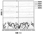
上記実施例1〜8及び比較例1〜6で製造された上部ボデーの透視歪量を測定し、先端部頂点側の終端部、上部頂点側及び後端部頂点側の終端部を結ぶ最短の曲線部分における透視歪量(分)を、図23〜28において示す。ここで、横軸で規定する位置の0mmは、先端部頂点側の終端部とした。また、該曲線部分と直交し上部ボデーの重心を含む面において、上部頂点から左右に渡る曲線部分における透視歪量(分)を、図29〜32において示す。ここで、横軸で規定する位置の0mmは、上部頂点部とした。 Measure the amount of perspective distortion of the upper body manufactured in Examples 1 to 8 and Comparative Examples 1 to 6, and connect the terminal end on the tip end side, the top apex side, and the terminal end on the rear end apex side. The perspective distortion amount (minutes) in the curved portion is shown in FIGS. Here, 0 mm at the position defined by the horizontal axis was defined as the end portion on the apex side. 29 to 32 show the perspective distortion amount (minutes) in the curved portion extending from the upper vertex to the left and right in the plane orthogonal to the curved portion and including the center of gravity of the upper body. Here, 0 mm at the position defined by the horizontal axis is the upper vertex.
実施例3および比較例3で製造された上部ボデーの透視歪量の測定は、車体の前後方向と直交する方向に2本の屈曲線を設けたことにより生じた車体の前後方向と平行する方向の2本の稜線から5cmを除いた部分で行った。なお、本発明における「透視歪量」は、特開2002−128909号公報の段落[0089]に示されているようなJIS R3212に準拠した測定方法により、上部ボデーの重心に光源を置いて測定したものである。 The measurement of the amount of perspective distortion of the upper body manufactured in Example 3 and Comparative Example 3 is a direction parallel to the front-rear direction of the vehicle body produced by providing two bending lines in a direction orthogonal to the front-rear direction of the vehicle body This was carried out at a portion excluding 5 cm from the two ridge lines. The “transparent distortion amount” in the present invention is measured by placing a light source at the center of gravity of the upper body by a measuring method based on JIS R3212 as shown in paragraph [0089] of JP-A-2002-128909. It is a thing.
上記実施例1〜8及び比較例1〜6で製造された上部ボデーを通した周囲の状況、景色の視認性の評価を、下記表2に示す。 Table 2 below shows the surrounding situation through the upper body manufactured in Examples 1 to 8 and Comparative Examples 1 to 6, and evaluation of the visibility of the scenery.
また、目視観察は、屋外で天気の良い日中に行い、上部ボデーの重心から、上部ボデーを通して遠方の外部を見て、外部の状況・景色をほとんど歪なく見ることができる場合を〇、視認性に支障をきたす歪が観察される場合を×と評価した。目視観察は、大人5名で行い過半数以上の評価を採用したが、各成形体における評価のバラつきはほとんどみられなかった。 In addition, visual observation should be performed outdoors on a sunny day. From the center of gravity of the upper body, the outside can be seen through the upper body and the external situation and scenery can be seen almost without distortion. The case where strain that disturbs sex was observed was evaluated as x. Visual observation was performed by five adults and more than half of the evaluations were adopted, but there was little variation in the evaluation of each molded product.
実施例1〜8の結果からわかるように、本発明の自動車車体の上部ボデーは、運転者が下方近傍を直接確認でき、さらに、搭乗者が外部の状況・景色をほとんど歪なく見ることができるという視認性に優れるという優れた効果を奏する。 As can be seen from the results of Examples 1 to 8, the upper body of the automobile body of the present invention allows the driver to directly confirm the vicinity near the lower side, and further allows the passenger to see the external situation / scenery with almost no distortion. It has the excellent effect of being excellent in visibility.
本発明の自動車車体の上部ボデーは、
1)先端部頂点側及び後端部頂点側の終端部で、上曲面への接線が水平面となす角度が85〜125°となるように形成されていること、
2)上部ボデーの重心から見た透視歪量の平均値が1.0分以下であること、及び
3)ある部分とその部分と5cm隔てて隣接する部分との透視歪量の差が、重心を含む地面に平行な面より上の部分において1.5分以下であること
を最大の特徴として備えるものであるが、上記特徴1)を備えない上部ボデーは、搭乗者が外部の状況・景色をほとんど歪なく見ることができるという視認性を確保することができない。
The upper body of the car body of the present invention is
1) It is formed so that the angle between the tangent to the upper curved surface and the horizontal plane is 85 to 125 ° at the end portions on the apex side and the apex side of the rear end.
2) The average value of the amount of perspective distortion seen from the center of gravity of the upper body is 1.0 minute or less, and 3) The difference in the amount of perspective distortion between a certain part and a part adjacent to that part by 5 cm is the center of gravity. The upper body that has a maximum feature of 1.5 minutes or less in the part above the plane parallel to the ground including the above-mentioned feature 1) does not have the above feature 1). It is not possible to ensure the visibility that the image can be viewed almost without distortion.
また、上記特徴2)及び3)のいずれも備えない比較例1及び比較例4の上部ボデーについては視認性が劣っている。 Moreover, the visibility of the upper bodies of Comparative Example 1 and Comparative Example 4 that do not include any of the above features 2) and 3) is poor.
また、上記特徴2)は備えるが上記特徴3)を備えない比較例2〜3及び5〜6の上部ボデーは視認性が劣っていることから、上記2)の特徴を備えるだけでは十分に視認性が確保できず、上記特徴3)を併せて備えることが重要であるといえる。 Moreover, since the upper bodies of Comparative Examples 2-3 and 5-6, which have the above feature 2) but do not have the above feature 3), have poor visibility, it is sufficiently visible only by having the above feature 2). Therefore, it can be said that it is important to provide the above feature 3) together.
なお、比較例2、比較例5の上部ボデーは、曲率[1/曲率半径(mm)]が1.4×10-2である2本の屈曲線の部分において透視歪量が大きくなっているが、実施例3、実施例8のように、この屈曲線の部分の厚さを薄くすることにより、透視歪量を低減し、上記特徴2)及び3)を満足するようにできる。屈曲線の部分におけるA×B2の値は、比較例2、比較例5では1.18×10-3[6(mm)×(1.4×10-2)2]であり、実施例3、実施例8では0.98×10-3[5(mm)×(1.4×10-2)2]である。 In the upper bodies of Comparative Example 2 and Comparative Example 5, the amount of perspective distortion is large at the two bent lines where the curvature [1 / curvature radius (mm)] is 1.4 × 10 −2 . However, as in the third and eighth embodiments, by reducing the thickness of the bent line portion, the amount of perspective distortion can be reduced and the above features 2) and 3) can be satisfied. The value of A × B 2 in the bent line portion is 1.18 × 10 −3 [6 (mm) × (1.4 × 10 −2 ) 2 ] in Comparative Example 2 and Comparative Example 5, and Example 3. In Example 8, it is 0.98 × 10 −3 [5 (mm) × (1.4 × 10 −2 ) 2 ].
本発明に係る自動車車体の上部ボデーは、軽量で、製造が簡単で、搭乗者が周囲の状況・景色を全面的に歪みなく見通すことができ、必要とされる剛性を備えたものであり、特に、超小型電気自動車等の超小型モビリティの自動車車体の上部ボデー車体に適したものである。 The upper body of the automobile body according to the present invention is lightweight, easy to manufacture, and allows the passenger to see the surrounding situation and scenery completely without distortion, and has the required rigidity. In particular, it is suitable for an upper body body of an automobile body of a micro mobility such as a micro electric car.
1:下部ボデー
1−1:底面
1−2:フランジ部
1−3:凸条部
1−4:サイドシル形状部
2:上部ボデー
2−1:前アッパーボデー
2−2:後アッパーボデー
2−3:ルーフ
3:フロア
4:枠部材
4−1:シートベルトショルダーアンカー
4−2:転落防止用部材
4−3:雨よけドア
5:前サスペンションサブフレーム
6:後サスペンションサブフレーム
7,7’:上部ボデー(ルーフ)の稜線部
8:乗降口を形成する開口部
9:バッテリー等の自動車部品
1: Lower body 1-1: Bottom surface 1-2: Flange part 1-3: Projection line part 1-4: Side sill shape part 2: Upper body 2-1: Front upper body 2-2: Rear upper body 2-3 : Roof 3: Floor 4: Frame member 4-1: Seat belt shoulder anchor 4-2: Member for prevention of falling 4-3: Door to prevent rain 5: Front suspension subframe 6:
Claims (11)
前記上部ボデーは、透明な熱可塑性樹脂組成物により形成されており、
前記上部ボデーは、卵の細く窄んだ先端部を車体前方側、卵の太く膨らんだ後端部を車体後方側とし、卵の先端部頂点と後端部頂点とを結ぶ直線を地面と略平行とし、地面側から下部の略1/3〜1/2を切り取ったような、略卵型上半部の形状をしており、
前記上部ボデーの上曲面は、前記2つの頂点を含む地面に垂直な断面において、前記上曲面への接線が水平となる上部頂点から、前記先端部頂点及び前記後端部頂点に向けて、前記上曲面への接線が水平面となす角度が連続的に増加し、前記先端部頂点側及び前記後端部頂点側の終端部で、前記上曲面への接線が水平面となす角度が85〜125°となるように形成されており、
前記上部ボデーは、前記上部ボデーの重心から見た透視歪量の平均値が1.0分以下であり、また、ある部分とその部分と5cm隔てて隣接する部分との透視歪量の差が、重心を含む地面に平行な面より上の部分において1.5分以下である、
ことを特徴とする自動車車体の上部ボデー。 An upper body of an automobile body formed by bonding and / or fastening an upper body, a lower body, etc.
The upper body is formed of a transparent thermoplastic resin composition,
The upper body has a narrowed tip of the egg at the front side of the vehicle body, a thickly swollen rear end of the egg at the rear side of the vehicle, and a straight line connecting the apex of the egg and the apex of the rear end is substantially the ground. It is parallel and has a shape of an approximately egg-shaped upper half, such as the lower part of about 1/3 to 1/2 cut off from the ground side,
The upper curved surface of the upper body, in a cross section perpendicular to the ground including the two vertices, from the upper vertex where the tangent to the upper curved surface is horizontal, toward the tip vertex and the rear vertex, The angle between the tangent to the upper curved surface and the horizontal plane increases continuously, and the angle between the tangent to the upper curved surface and the horizontal plane is 85 to 125 ° at the end portions on the apex side and the rear end apex side. It is formed so that
The upper body has an average value of the amount of perspective distortion as viewed from the center of gravity of the upper body of 1.0 minute or less, and there is a difference in the amount of perspective distortion between a certain part and a part adjacent to the part by 5 cm. , 1.5 minutes or less in the part above the plane parallel to the ground including the center of gravity,
An upper body of an automobile body characterized by that.
前記上部ボデーは、透明な熱可塑性樹脂組成物により形成されており、
前記上部ボデーは、卵の細く窄んだ先端部を車体前方側、卵の太く膨らんだ後端部を車体後方側とし、卵の先端部頂点と後端部頂点とを結ぶ直線を地面と略平行とし、地面側から下部の略1/3〜1/2を切り取ったような、略卵型上半部の形状をしており、
前記上部ボデーの上曲面は、前記2つの頂点を含む地面に垂直な断面において、前記上曲面への接線が水平となる上部頂点から、前記先端部頂点及び前記後端部頂点に向けて、前記上曲面への接線が水平面となす角度が連続的に増加し、前記先端部頂点側及び前記後端部頂点側の終端部で、前記上曲面への接線が水平面となす角度が85〜125°となるように形成されており、
前記上部ボデーには、前記先端部頂点、前記上部頂点及び前記後端部頂点を結ぶ最短の曲線に対して左右対称で、前記最短の曲線に略平行な2本の稜線部が設けられており、
前記上部ボデーの前記2本の稜線部から5cm以内の部分を除く部分は、前記上部ボデーの重心から見た透視歪量の平均値が1.0分以下であり、また、ある部分とその部分と5cm隔てて隣接する部分との透視歪量の差が、重心を含む地面に平行な面より上の部分において1.5分以下である、
ことを特徴とする自動車車体の上部ボデー。 An upper body of an automobile body formed by bonding and / or fastening an upper body, a lower body, etc.
The upper body is formed of a transparent thermoplastic resin composition,
The upper body has a narrowed tip of the egg at the front side of the vehicle body, a thickly swollen rear end of the egg at the rear side of the vehicle, and a straight line connecting the apex of the egg and the apex of the rear end is substantially the ground. It is parallel and has a shape of an approximately egg-shaped upper half, such as the lower part of about 1/3 to 1/2 cut off from the ground side,
The upper curved surface of the upper body, in a cross section perpendicular to the ground including the two vertices, from the upper vertex where the tangent to the upper curved surface is horizontal, toward the tip vertex and the rear vertex, The angle between the tangent to the upper curved surface and the horizontal plane increases continuously, and the angle between the tangent to the upper curved surface and the horizontal plane is 85 to 125 ° at the end portions on the apex side and the rear end apex side. It is formed so that
The upper body is provided with two ridge lines that are symmetrical with respect to the shortest curve connecting the tip apex, the upper apex, and the rear end apex, and are substantially parallel to the shortest curve. ,
In the portion excluding the portion within 5 cm from the two ridges of the upper body, the average value of the amount of perspective distortion as viewed from the center of gravity of the upper body is 1.0 minute or less. And the difference in the amount of perspective distortion between adjacent parts separated by 5 cm is 1.5 minutes or less in the part above the plane parallel to the ground including the center of gravity.
An upper body of an automobile body characterized by that.
A×B2≦1.07×10⁻³ (I) The thickness (mm) A in the normal direction of the upper body and the curvature [1 / curvature radius (mm)] B satisfy the following formula (I) (however, when having a ridge line part, from the ridge line part: The upper body of the automobile body according to any one of claims 1 to 4, wherein a portion within 5 cm is excluded).
A × B 2 ≦ 1.07 × 10 −3 (I)
Priority Applications (1)
| Application Number | Priority Date | Filing Date | Title |
|---|---|---|---|
| JP2014261279A JP6431362B2 (en) | 2014-12-24 | 2014-12-24 | Substantially egg-shaped upper body of an automobile body formed of a transparent thermoplastic resin composition |
Applications Claiming Priority (1)
| Application Number | Priority Date | Filing Date | Title |
|---|---|---|---|
| JP2014261279A JP6431362B2 (en) | 2014-12-24 | 2014-12-24 | Substantially egg-shaped upper body of an automobile body formed of a transparent thermoplastic resin composition |
Publications (2)
| Publication Number | Publication Date |
|---|---|
| JP2016120802A true JP2016120802A (en) | 2016-07-07 |
| JP6431362B2 JP6431362B2 (en) | 2018-11-28 |
Family
ID=56327028
Family Applications (1)
| Application Number | Title | Priority Date | Filing Date |
|---|---|---|---|
| JP2014261279A Active JP6431362B2 (en) | 2014-12-24 | 2014-12-24 | Substantially egg-shaped upper body of an automobile body formed of a transparent thermoplastic resin composition |
Country Status (1)
| Country | Link |
|---|---|
| JP (1) | JP6431362B2 (en) |
Cited By (2)
| Publication number | Priority date | Publication date | Assignee | Title |
|---|---|---|---|---|
| JP2019043186A (en) * | 2017-08-30 | 2019-03-22 | トヨタ自動車株式会社 | Outer air introduction structure of ultracompact mobility |
| JP2023001307A (en) * | 2017-10-24 | 2023-01-04 | 旭化成株式会社 | Methacrylic resin composition, and molded body |
Citations (10)
| Publication number | Priority date | Publication date | Assignee | Title |
|---|---|---|---|---|
| JPS5940980A (en) * | 1982-08-31 | 1984-03-06 | Yamaha Motor Co Ltd | Car body |
| JPS6061237A (en) * | 1983-09-14 | 1985-04-09 | Yamaha Motor Co Ltd | Manufacture of car body of synthetic resin |
| JPS61166776A (en) * | 1985-01-18 | 1986-07-28 | Honda Motor Co Ltd | Body for miniature car |
| JPH06156314A (en) * | 1992-11-19 | 1994-06-03 | Toray Ind Inc | Two passenger automobile |
| JP2002128909A (en) * | 2000-10-25 | 2002-05-09 | Teijin Chem Ltd | Window product made of resin |
| JP3108250U (en) * | 2004-10-15 | 2005-04-14 | 鈴木 茂 | Auto body structure |
| US20120068496A1 (en) * | 2010-09-21 | 2012-03-22 | Tata Technologies Pte Limited | Cost-effective, lightweight, thermoplastic automotive body structure manufactured by single step roto-molding process |
| JP2012111142A (en) * | 2010-11-25 | 2012-06-14 | Teijin Chem Ltd | Weather resistant resin glazing with excellent color tone stability |
| JP2014113907A (en) * | 2012-12-10 | 2014-06-26 | Kojima Press Industry Co Ltd | Ultracompact mobility |
| WO2014203782A1 (en) * | 2013-06-21 | 2014-12-24 | 帝人株式会社 | Vehicle of monocoque construction formed from thermoplastic resin members |
-
2014
- 2014-12-24 JP JP2014261279A patent/JP6431362B2/en active Active
Patent Citations (10)
| Publication number | Priority date | Publication date | Assignee | Title |
|---|---|---|---|---|
| JPS5940980A (en) * | 1982-08-31 | 1984-03-06 | Yamaha Motor Co Ltd | Car body |
| JPS6061237A (en) * | 1983-09-14 | 1985-04-09 | Yamaha Motor Co Ltd | Manufacture of car body of synthetic resin |
| JPS61166776A (en) * | 1985-01-18 | 1986-07-28 | Honda Motor Co Ltd | Body for miniature car |
| JPH06156314A (en) * | 1992-11-19 | 1994-06-03 | Toray Ind Inc | Two passenger automobile |
| JP2002128909A (en) * | 2000-10-25 | 2002-05-09 | Teijin Chem Ltd | Window product made of resin |
| JP3108250U (en) * | 2004-10-15 | 2005-04-14 | 鈴木 茂 | Auto body structure |
| US20120068496A1 (en) * | 2010-09-21 | 2012-03-22 | Tata Technologies Pte Limited | Cost-effective, lightweight, thermoplastic automotive body structure manufactured by single step roto-molding process |
| JP2012111142A (en) * | 2010-11-25 | 2012-06-14 | Teijin Chem Ltd | Weather resistant resin glazing with excellent color tone stability |
| JP2014113907A (en) * | 2012-12-10 | 2014-06-26 | Kojima Press Industry Co Ltd | Ultracompact mobility |
| WO2014203782A1 (en) * | 2013-06-21 | 2014-12-24 | 帝人株式会社 | Vehicle of monocoque construction formed from thermoplastic resin members |
Cited By (3)
| Publication number | Priority date | Publication date | Assignee | Title |
|---|---|---|---|---|
| JP2019043186A (en) * | 2017-08-30 | 2019-03-22 | トヨタ自動車株式会社 | Outer air introduction structure of ultracompact mobility |
| JP2023001307A (en) * | 2017-10-24 | 2023-01-04 | 旭化成株式会社 | Methacrylic resin composition, and molded body |
| JP7357749B2 (en) | 2017-10-24 | 2023-10-06 | 旭化成株式会社 | Methacrylic resin composition, molded body |
Also Published As
| Publication number | Publication date |
|---|---|
| JP6431362B2 (en) | 2018-11-28 |
Similar Documents
| Publication | Publication Date | Title |
|---|---|---|
| EP3012175B1 (en) | Vehicle of monocoque construction formed from thermoplastic resin members | |
| JP4186002B2 (en) | RESIN COMPOSITION, THERMOPLASTIC RESIN LAMINATE USING SAME, AND METHOD FOR PRODUCING THEM | |
| EP2377703A1 (en) | Door structure module | |
| EP2496464B1 (en) | Front end of a motor vehicle | |
| PL190583B1 (en) | Composote glazing panel of glass and aplastic, assembly incorporating such composite glazing panel, method of making such assembly and method of determining optimum geometric parameters of that panel and glazing panel having such optimised parameters | |
| JP6431362B2 (en) | Substantially egg-shaped upper body of an automobile body formed of a transparent thermoplastic resin composition | |
| CN106432617B (en) | Composition for preparing lightweight transparent composite material, method for preparing composite material and composite material prepared thereby | |
| JP2008133141A (en) | Laminated glass | |
| JP2003201114A (en) | Modified silica composition, transparent resin composition, thermoplastic resin laminated body using these, automobile parts and method for manufacturing these | |
| CN114714712A (en) | Laminated composite roof panel with internal partial structural reinforcement for motor vehicles | |
| JP6799505B2 (en) | Resin substrate for pillarless front window | |
| JP3862075B2 (en) | RESIN COMPOSITION, LAMINATE USING SAME, AUTOMOBILE PARTS AND METHOD FOR PRODUCING THEM | |
| JP2004331883A (en) | Intermediate of composite resin composition, composite resin composition, method for producing intermediate of composite resin composition and method for producing composite resin composition | |
| GB2419330A (en) | Structural element for a vehicle | |
| JP2004292698A (en) | Resin composition, filler, and method for manufacturing resin composition | |
| US20140087144A1 (en) | Resin molded product | |
| WO2021002253A1 (en) | Glass | |
| JP3991939B2 (en) | Automotive window materials | |
| JP2006232244A (en) | Wiper soft to driver's eyes | |
| EP3519217B1 (en) | Vehicle with two a-pillars and a windscreen | |
| JP2005015519A (en) | Resin composition and method for producing the same | |
| KR200299074Y1 (en) | The sunlight cover for auto | |
| JP6806038B2 (en) | Pillar structure for vehicles | |
| KR101002502B1 (en) | Sunvisior of vehicle that installationis possible regardless of vehicle type | |
| JP2004285192A (en) | Composition, resin composition, method for producing the composition, method for producing the resin composition, and molded form |
Legal Events
| Date | Code | Title | Description |
|---|---|---|---|
| RD04 | Notification of resignation of power of attorney |
Free format text: JAPANESE INTERMEDIATE CODE: A7424 Effective date: 20170830 |
|
| A621 | Written request for application examination |
Free format text: JAPANESE INTERMEDIATE CODE: A621 Effective date: 20170905 |
|
| A977 | Report on retrieval |
Free format text: JAPANESE INTERMEDIATE CODE: A971007 Effective date: 20180621 |
|
| A131 | Notification of reasons for refusal |
Free format text: JAPANESE INTERMEDIATE CODE: A131 Effective date: 20180731 |
|
| A521 | Request for written amendment filed |
Free format text: JAPANESE INTERMEDIATE CODE: A523 Effective date: 20180926 |
|
| TRDD | Decision of grant or rejection written | ||
| A01 | Written decision to grant a patent or to grant a registration (utility model) |
Free format text: JAPANESE INTERMEDIATE CODE: A01 Effective date: 20181009 |
|
| A61 | First payment of annual fees (during grant procedure) |
Free format text: JAPANESE INTERMEDIATE CODE: A61 Effective date: 20181102 |
|
| R150 | Certificate of patent or registration of utility model |
Ref document number: 6431362 Country of ref document: JP Free format text: JAPANESE INTERMEDIATE CODE: R150 |