JP2016118317A - Unit for compressor, compressor, and refrigeration circuit - Google Patents
Unit for compressor, compressor, and refrigeration circuit Download PDFInfo
- Publication number
- JP2016118317A JP2016118317A JP2014257204A JP2014257204A JP2016118317A JP 2016118317 A JP2016118317 A JP 2016118317A JP 2014257204 A JP2014257204 A JP 2014257204A JP 2014257204 A JP2014257204 A JP 2014257204A JP 2016118317 A JP2016118317 A JP 2016118317A
- Authority
- JP
- Japan
- Prior art keywords
- oil
- compressor
- pipe
- lubricating oil
- detection sensor
- Prior art date
- Legal status (The legal status is an assumption and is not a legal conclusion. Google has not performed a legal analysis and makes no representation as to the accuracy of the status listed.)
- Granted
Links
Images
Classifications
-
- F—MECHANICAL ENGINEERING; LIGHTING; HEATING; WEAPONS; BLASTING
- F25—REFRIGERATION OR COOLING; COMBINED HEATING AND REFRIGERATION SYSTEMS; HEAT PUMP SYSTEMS; MANUFACTURE OR STORAGE OF ICE; LIQUEFACTION SOLIDIFICATION OF GASES
- F25B—REFRIGERATION MACHINES, PLANTS OR SYSTEMS; COMBINED HEATING AND REFRIGERATION SYSTEMS; HEAT PUMP SYSTEMS
- F25B31/00—Compressor arrangements
- F25B31/002—Lubrication
- F25B31/004—Lubrication oil recirculating arrangements
-
- F—MECHANICAL ENGINEERING; LIGHTING; HEATING; WEAPONS; BLASTING
- F25—REFRIGERATION OR COOLING; COMBINED HEATING AND REFRIGERATION SYSTEMS; HEAT PUMP SYSTEMS; MANUFACTURE OR STORAGE OF ICE; LIQUEFACTION SOLIDIFICATION OF GASES
- F25B—REFRIGERATION MACHINES, PLANTS OR SYSTEMS; COMBINED HEATING AND REFRIGERATION SYSTEMS; HEAT PUMP SYSTEMS
- F25B43/00—Arrangements for separating or purifying gases or liquids; Arrangements for vaporising the residuum of liquid refrigerant, e.g. by heat
- F25B43/02—Arrangements for separating or purifying gases or liquids; Arrangements for vaporising the residuum of liquid refrigerant, e.g. by heat for separating lubricants from the refrigerant
-
- F—MECHANICAL ENGINEERING; LIGHTING; HEATING; WEAPONS; BLASTING
- F25—REFRIGERATION OR COOLING; COMBINED HEATING AND REFRIGERATION SYSTEMS; HEAT PUMP SYSTEMS; MANUFACTURE OR STORAGE OF ICE; LIQUEFACTION SOLIDIFICATION OF GASES
- F25B—REFRIGERATION MACHINES, PLANTS OR SYSTEMS; COMBINED HEATING AND REFRIGERATION SYSTEMS; HEAT PUMP SYSTEMS
- F25B2600/00—Control issues
- F25B2600/25—Control of valves
- F25B2600/2519—On-off valves
-
- F—MECHANICAL ENGINEERING; LIGHTING; HEATING; WEAPONS; BLASTING
- F25—REFRIGERATION OR COOLING; COMBINED HEATING AND REFRIGERATION SYSTEMS; HEAT PUMP SYSTEMS; MANUFACTURE OR STORAGE OF ICE; LIQUEFACTION SOLIDIFICATION OF GASES
- F25B—REFRIGERATION MACHINES, PLANTS OR SYSTEMS; COMBINED HEATING AND REFRIGERATION SYSTEMS; HEAT PUMP SYSTEMS
- F25B2700/00—Sensing or detecting of parameters; Sensors therefor
- F25B2700/03—Oil level
Abstract
Description
本発明は、冷熱設備に設けられている圧縮機の故障を防止する圧縮機用ユニット、圧縮機、及び冷媒回路に関する。 The present invention relates to a compressor unit, a compressor, and a refrigerant circuit that prevent failure of a compressor provided in a cooling facility.
例えば、店舗等に設置される冷却ユニット(クーリングユニット)などの冷熱設備は、室外機として、圧縮機、電動機、凝縮器、等を同一の架台に取り付けてユニット化したコンデンシングユニットを有している。
コンデンシングユニットと組み合わされる蒸発器ユニット(ユニットクーラ、ショーケース用クーラ等)は、その台数や形状など、個々の要件に対して多種多様である。
例えば、蒸発器ユニットの台数や、接続配管の長さが変わることによって、蒸発器ユニットや接続配管に冷凍機油(潤滑油)が滞留し、圧縮機での油面低下を発生することがあった。また、油不足に起因して圧縮機に不具合が発生する可能性があった。
For example, refrigeration equipment such as a cooling unit (cooling unit) installed in a store or the like has a condensing unit that is unitized by attaching a compressor, an electric motor, a condenser, etc. to the same base as an outdoor unit. Yes.
Evaporator units (unit coolers, showcase coolers, etc.) combined with a condensing unit have a wide variety according to individual requirements such as the number and shape.
For example, refrigeration oil (lubricating oil) may accumulate in the evaporator unit and the connection pipe due to changes in the number of evaporator units and the length of the connection pipe, resulting in a decrease in the oil level in the compressor. . In addition, there is a possibility that the compressor may malfunction due to oil shortage.
特許文献1には、スクロール圧縮機を含む冷却ユニットにおいてスクロール圧縮機から吐出される冷媒ガス中に混入した冷凍機油を分離回収する冷凍ユニットが記載されている。この冷凍ユニットでは、蒸発温度が所定の冷凍温度以下であることを検知して、分離回収した冷凍機油を圧力差によってスクロール圧縮機へ吸引することにより、潤滑不良を解消する技術が記載されている。
しかしながら、特許文献1に記載の発明においては、圧縮機内部の冷凍機油の油面の量が確認できないため、確実な潤滑不良の解消が難しかった。
However, in the invention described in
この発明は、冷熱設備の圧縮機に取り付けることが可能であり、油不足による圧縮機の不具合の発生を防止することができる圧縮機用ユニット、圧縮機、及び冷媒回路を提供することを目的とする。 An object of the present invention is to provide a compressor unit, a compressor, and a refrigerant circuit that can be attached to a compressor of a cold-heating facility and can prevent the occurrence of a malfunction of the compressor due to lack of oil. To do.
本発明の第一の態様によれば、圧縮機用ユニットは、圧縮機の外面であって前記圧縮機の内部に溜められる油の油面よりも下側に接続される第一の配管と、前記圧縮機の外面であって前記圧縮機の油面よりも上側に接続される第二の配管と、前記第一の配管及び前記第二の配管が接続されるタンクと、前記タンクに取り付けられ前記タンクの内部に溜められる油の油面を検出する油検出センサであって、前記タンクの油面よりも下側に取り付けられた油検出センサと、を備えることを特徴とする。 According to the first aspect of the present invention, the compressor unit includes an outer surface of the compressor and a first pipe connected to a lower side than an oil surface of the oil stored in the compressor; A second pipe connected to the outer surface of the compressor and above the oil level of the compressor; a tank to which the first pipe and the second pipe are connected; and a tank attached to the tank. An oil detection sensor for detecting an oil level of oil stored in the tank, the oil detection sensor being mounted below the oil level of the tank.
このような構成によれば、第一の配管を介して油がタンクに導入されるとともに、第二の配管によって圧縮機内の気体の圧力とタンク内の気体の圧力とが均等化され、タンク内に圧縮機の内部に溜められる油面と同じ高さの油面が形成される。油検出センサを参照してタンクに形成される油面を検出することにより、圧縮機の内部に溜められる油の油面の状態を確認することができる。圧縮機内部の油面を確認することにより、油不足に起因する圧縮機の故障を防止することができる。 According to such a configuration, the oil is introduced into the tank through the first pipe, and the gas pressure in the compressor and the gas pressure in the tank are equalized by the second pipe. Thus, an oil surface having the same height as the oil surface stored in the compressor is formed. By detecting the oil level formed in the tank with reference to the oil detection sensor, the state of the oil level of the oil accumulated in the compressor can be confirmed. By checking the oil level inside the compressor, it is possible to prevent the compressor from being damaged due to oil shortage.
上記圧縮機用ユニットにおいて、前記油の供給源から前記圧縮機へ接続する第一の供給配管及び第二の供給配管と、前記第二の供給配管を開閉する弁と、を備えてもよい。 The compressor unit may include a first supply pipe and a second supply pipe connected from the oil supply source to the compressor, and a valve for opening and closing the second supply pipe.
このような構成によれば、確認された圧縮機内部の油面の高さに応じて油の供給源から油を供給するように弁を操作することによって、圧縮機内の油の不足を解消することができる。 According to such a configuration, the shortage of oil in the compressor is eliminated by operating the valve to supply oil from the oil supply source according to the confirmed oil level in the compressor. be able to.
上記圧縮機用ユニットにおいて、前記弁を制御する制御部を備え、前記制御部は、前記油検出センサが油を検出した場合に前記弁を閉じ、前記油検出センサが油を検出しない場合に前記弁を開く制御を行ってよい。 The compressor unit includes a control unit that controls the valve. The control unit closes the valve when the oil detection sensor detects oil, and the control unit closes the valve when the oil detection sensor does not detect oil. Control to open the valve may be performed.
このような構成によれば、制御部が油面の状態に応じて弁の制御を行うことによって、自動的に油の供給源に溜められた油を圧縮機に供給することができる。 According to such a configuration, the control unit controls the valve in accordance with the state of the oil level, so that the oil stored in the oil supply source can be automatically supplied to the compressor.
また、本発明の第二の態様によれば、圧縮機は、上記いずれかの圧縮機用ユニットを備えることを特徴とする。 According to a second aspect of the present invention, the compressor includes any one of the compressor units described above.
また、本発明の第三の態様によれば、冷媒回路は、上記の圧縮機を備えることを特徴とする。 Moreover, according to the 3rd aspect of this invention, a refrigerant circuit is provided with said compressor.
本発明によれば、油不足による圧縮機の不具合の発生を防止することができる。 According to the present invention, it is possible to prevent the occurrence of a compressor failure due to oil shortage.
以下、本発明の実施形態の冷熱設備である冷却ユニット1について図面を参照して詳細に説明する。
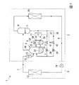
図1に示すように、本実施形態の冷却ユニット1は、互いに接続されている室外機2(コンデンシングユニット)と室内機3(蒸発器ユニット)とを備え、冷媒管(ガス管7及び液管8)からなる冷媒回路を有している。なお、室外機2に対して順次並列に接続すれば、室内機3の台数を増やしてもよい。
Hereinafter, a
As shown in FIG. 1, the
室外機2は、ガス管7を介して導入される冷媒ガスを圧縮する圧縮機4と、圧縮機4に取り付けて使用される圧縮機用ユニット5と、圧縮機4から吐出された冷媒ガスに含まれている潤滑油L(冷凍機油)を分離するオイルセパレータ9と、室外空気と冷媒とを熱交換して凝縮する凝縮器10(室外熱交換器)と、制御部11と、を主な構成要素として備えている。さらに、室外機2は、ガス管7を介して圧縮機4に供給される冷媒ガスの気液分離を行うアキュムレータ12(液分離器)を有している。
The
室内機3は、室内空気と冷媒とを熱交換して蒸発させる蒸発器13(室内熱交換器)と、膨張弁14と、を主な構成要素として備えている。膨張弁14は、凝縮器10から液管8を介して導入される高温・高圧の液冷媒を蒸発しやすい状態に減圧する弁である。
The indoor unit 3 includes an evaporator 13 (indoor heat exchanger) that exchanges heat between indoor air and refrigerant and evaporates, and an
アキュムレータ12は、圧縮機4の吸引管15(蒸発器13と圧縮機4との間のガス管7)の上流側に設けられている圧力容器である。アキュムレータ12としては、容器内に液冷媒を蓄積し、蒸気となった冷媒のみを圧縮機4に戻す構造のものを採用することができる。
The
圧縮機4は、低圧の状態で導入された冷媒ガスを圧縮してオイルセパレータ9へと吐出する機械である。
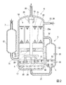
図2に示すように、圧縮機4は、スクロール型圧縮機構17と、スクロール型圧縮機構17を駆動する電動モータ18と、電動モータ18が発する駆動力をスクロール型圧縮機構17に伝達する回転シャフト19(駆動軸)とがハウジング20内に収容された密閉式構造となっている。
The compressor 4 is a machine that compresses the refrigerant gas introduced in a low pressure state and discharges it to the oil separator 9.
As shown in FIG. 2, the compressor 4 includes a scroll
電動モータ18は、ロータ21とステータ22とからなり、電気エネルギーにより回転シャフト19を駆動する電動機である。
スクロール型圧縮機構17は、固定スクロール24及び旋回スクロール25と、を有している。電動モータ18とスクロール型圧縮機構17とは、回転シャフト19を介して連結されている。
The
The scroll
回転シャフト19の上端は、サブベアリング26を介してハウジング20に回転自在に固定され、回転シャフト19の下端は、メインベアリング27を介してハウジング20のフレーム28に回転自在に固定されている。
電動モータ18が回転シャフト19を駆動することにより、スクロール型圧縮機構17の旋回スクロール25が回転する。圧縮機4は、潤滑油Lを用いることで圧縮機4内の各摺動部の潤滑を行っている。潤滑油Lは、ハウジング20の下部に貯留される。即ち、圧縮機4のハウジング20の底部は、スクロール型圧縮機構17などを潤滑する潤滑油Lが貯留されるオイル溜めとして機能する。潤滑油Lがハウジング20に溜められることにより、油面S1が形成される。
An upper end of the rotating
When the
図示しないが、回転シャフト19の内部には軸方向に沿って油路が形成されており、ハウジング20の下部に貯留された潤滑油Lは、回転シャフト19に形成されている油路を介してメインベアリング27等の摺動部に供給される。
Although not shown, an oil path is formed along the axial direction inside the
オイルセパレータ9は、圧縮機4の下流側に設けられ、吐出管30(圧縮機4と凝縮器10との間のガス管7)を通って送り込まれる潤滑油Lが混在した冷媒ガスから、遠心力等により潤滑油Lを分離する装置である。オイルセパレータ9は、上下が封鎖された円筒形状を有しており、分離された潤滑油Lを貯留可能である。即ち、オイルセパレータ9は、潤滑油Lの供給源として機能させることができる。
The oil separator 9 is provided on the downstream side of the compressor 4 and is centrifuged from the refrigerant gas mixed with the lubricating oil L fed through the discharge pipe 30 (the
次に、冷却ユニット1に追加設置可能な圧縮機用ユニット5の詳細について説明する。
圧縮機用ユニット5は、圧縮機4のハウジング20の圧縮機4の内部に溜められる潤滑油Lの油面S1よりも下側に接続される第一の配管31と、油面S1よりも上側に接続される第二の配管32と、第一の配管31及び第二の配管32を介して圧縮機4のハウジング20に接続されている油溜33(タンク)と、を有している。
Next, details of the
The
第一の配管31は、圧縮機4の内部に溜められている潤滑油Lを油溜33に送るための配管である。第一の配管31は圧縮機4のハウジング20の外面20aに接続されている。第一の配管31は、圧縮機4のハウジング20の内部に僅かでも潤滑油Lが溜まっていれば、油溜33に潤滑油Lが送られるように、圧縮機4のハウジング20の底部に接続されている。
第二の配管32は、圧縮機4のハウジング20の外面20aに接続されている。第二の配管32は、圧縮機4に使用される潤滑油Lの総量等に基づき、最も油面S1が高くなった場合においても、第二の配管32に潤滑油Lが流入しない様な位置に接続されている。
The
The
油溜33は、潤滑油Lを貯留可能な容器であり、密閉式構造となっている。第一の配管31は、油溜33の底部に接続されている。第二の配管32は、油溜33の上部に接続されている。
The
油溜33の上下には、油溜33に貯留された潤滑油Lの油面S2を検出する第一の油検出センサ35及び第二の油検出センサ36が取り付けられている。第一の油検出センサ35及び第二の油検出センサ36は、設置個所の潤滑油Lの有無を検出可能な検出器であり、センサ表面に潤滑油Lが触れることにより制御器に信号を送信するように構成されている。即ち、第一の油検出センサ35及び第二の油検出センサ36は、制御部11と接続されており、制御部11は、第一の油検出センサ35及び第二の油検出センサ36から受信する信号に応じて制御を行う。
Above and below the
第一の油検出センサ35は、圧縮機4に使用される潤滑油Lの総量や、所望される制御方法に基づいて配置されている。具体的には、圧縮機4に溜められている潤滑油Lの量が適量である場合に、油溜33に形成される油面S2よりも下方に配置されている。即ち、圧縮機4のハウジング20に貯留された潤滑油Lの量が適量である場合に、潤滑油Lを検出するように配置されている。
The first
第二の油検出センサ36は、圧縮機4に使用される潤滑油Lの総量や、所望される制御方法に基づいて、第一の油検出センサ35の上方に配置されている。具体的には、圧縮機4に溜められている潤滑油Lの量が適量である場合に、油溜33に形成される油面S2よりも上方に配置されている。即ち、圧縮機4のハウジング20に貯留された潤滑油Lの量が適量である場合に、潤滑油Lを検出しないように配置されている。
The second
図1に示すように、圧縮機用ユニット5は、オイルセパレータ9に貯留された潤滑油Lを圧縮機4に送る第一の供給配管37及び第二の供給配管38を有している。第一の供給配管37及び第二の供給配管38の第一の端部は、オイルセパレータ9の容器の下部に接続されている。第一の供給配管37及び第二の供給配管38の第一の端部とは反対側の第二の端部は、圧縮機4のハウジング20の上部に接続されている。
第一の供給配管37及び第二の供給配管38は、互いに独立して形成されてもよいし、図1に示すように、途中で分岐してもよい。
As shown in FIG. 1, the
The
第一の供給配管37及び第二の供給配管38にはキャピラリチューブ等の絞り部39が設けられている。第一の供給配管37には、第一の供給配管37を開閉する第一の電磁弁41が設けられている。即ち、第一の電磁弁41を開状態とすることにより、第一の供給配管37を流れる潤滑油Lを流し、第一の電磁弁41を閉状態とすることにより、第一の供給配管37を流れる潤滑油Lを止めることができる。
The
第二の供給配管38には、第一の供給配管37に設けられている第一の電磁弁41と同様の第二の電磁弁42が設けられている。
第一の電磁弁41及び第二の電磁弁42は、制御部11と接続されている。即ち、第一の電磁弁41及び第二の電磁弁42は、制御部11から送信される信号に基づいて開閉させることができる。
The
The first electromagnetic valve 41 and the second
制御部11は、第一の油検出センサ35及び第二の油検出センサ36が潤滑油Lを検出した場合、即ち、潤滑油Lが第二の油検出センサ36の位置よりも多く貯留されている場合は、第二の電磁弁42を閉状態にする。即ち、第二の油検出センサ36が潤滑油Lを検出した場合、制御部11は、圧縮機4の内部の油面S1も十分に貯留されていると判断し、潤滑油Lの供給源であるオイルセパレータ9から潤滑油Lを送らない。
When the first
制御部11は、第一の油検出センサ35のみが潤滑油Lを検出した場合、即ち、油面S2が第一の油検出センサ35と第二の油検出センサ36の間の位置よりにある場合は、第二の電磁弁42を閉状態にする。即ち、第一の油検出センサ35のみ潤滑油Lを検出した場合、制御部11は、圧縮機4の内部の油面S1が適正であると判断し、潤滑油Lの供給源であるオイルセパレータ9から潤滑油Lを送らない。
When only the first
制御部11は、第一の油検出センサ35及び第二の油検出センサ36が潤滑油Lを検出しない場合、即ち、潤滑油Lが第一の油検出センサ35の位置よりも少なく貯留されている場合は、第二の電磁弁42を開状態にする。即ち、第一の油検出センサ35が潤滑油Lを検出しない場合、制御部11は、圧縮機4の内部の潤滑油Lの油面S1が低下しており、潤滑油Lが不十分であると判断し、潤滑油Lの供給源であるオイルセパレータ9から潤滑油Lを送る。
When the first
また、第一の電磁弁41は基本的に常時開状態とされている。即ち、オイルセパレータ9に貯留されている潤滑油Lは、通常状態において第一の供給配管37を介して圧縮機4の内部に供給される。第一の電磁弁41の制御方法はこれに限ることはなく、潤滑油Lの量が十分と判断される場合、第一の電磁弁41を閉じる制御を行ってもよい。例えば、第一の油検出センサ35及び第二の油検出センサ36が潤滑油Lを検出した場合、即ち、潤滑油Lが第二の油検出センサ36の位置よりも多く貯留されている場合に、第一の電磁弁41を閉じる制御を行うものとしてもよい。
The first solenoid valve 41 is basically always open. That is, the lubricating oil L stored in the oil separator 9 is supplied into the compressor 4 through the
圧縮機用ユニット5は、既存の冷熱設備に設けられている汎用の圧縮機4に取り付けることができる。油溜33は、所定のブラケット43を用いて圧縮機4に一体となるように取り付けることができる。油溜33が圧縮機4と一体となるように取り付けられていることによって、圧縮機4の振動により、第一の配管31及び第二の配管32が劣化することを防止することができる。
The
次に、本実施形態の圧縮機用ユニット5の作用について説明する。
圧縮機4のハウジング20の内部に潤滑油Lが貯留され油面S1が形成されると、第一の配管31を介して潤滑油Lが油溜33に導入される。また、第二の配管32によって圧縮機4内の気体の圧力と油溜33内の気体の圧力とが均等化され、油溜33内に圧縮機4の内部に溜められる油面S1と同じ高さの油面S2が形成される。
Next, the operation of the
When the lubricating oil L is stored inside the
例えば、潤滑油Lが蒸発器13や、冷媒管などに滞留し、圧縮機4の内部に貯留されている潤滑油Lの油面S1の低下が生じた場合、第一の油検出センサ35が潤滑油Lを検出しなくなる。これにより、制御部11は、第二の電磁弁42を開状態にする。第二の電磁弁42が開状態となることによって、オイルセパレータ9に貯留されている潤滑油Lが圧縮機4のハウジング20の内部に送られて、潤滑油Lの油面S1が上昇する。圧縮機4の潤滑油Lが十分になると、第一の油検出センサ35が潤滑油Lを検出して制御部11が第二の電磁弁42を閉じて、第二の供給配管38を介して潤滑油Lが供給されなくなる。
For example, when the lubricating oil L stays in the
上記実施形態によれば、第一の配管31を介して潤滑油Lが油溜33に導入されるとともに、第二の配管32によって圧縮機4内の気体の圧力と油溜33内の気体の圧力とが均等化され、油溜33内に圧縮機4の内部に溜められる油面S1と同じ高さの油面S2が形成される。第一の油検出センサ35を参照して油溜33に形成される油面S2を検出することにより、圧縮機4の内部に溜められる潤滑油Lの油面S1の状態を確認することができる。圧縮機4内部の油面S1を確認することにより、潤滑油不足に起因する圧縮機4の故障を防止することができる。
According to the above embodiment, the lubricating oil L is introduced into the
また、確認された圧縮機4内部の油面S1の高さに応じて潤滑油Lの供給源であるオイルセパレータ9から潤滑油Lを供給するように第二の電磁弁42を操作することによって、圧縮機4内の油の不足を解消することができる。
Further, by operating the second
また、制御部11が油面S2の状態に応じて第二の電磁弁42の制御を行うことによって、自動的にオイルセパレータ9に溜められた潤滑油Lを圧縮機4に供給することができる。
Further, the
なお、本発明の技術範囲は上記の実施形態に限定されるものではなく、本発明の趣旨を逸脱しない範囲において、種々の変更を加えることが可能である。
例えば、上記実施形態では、冷熱設備として冷却ユニット1を用いて圧縮機用ユニット5について説明したが、本実施形態の圧縮機用ユニット5は冷却ユニット1に限らず、他の冷熱設備にも適用可能である。本実施形態の圧縮機用ユニット5は、例えば、四方弁などの切換え弁を用いて冷媒の流れを逆転させる空気調和機にも適用することができる。
The technical scope of the present invention is not limited to the above embodiment, and various modifications can be made without departing from the spirit of the present invention.
For example, in the above-described embodiment, the
また、オイルセパレータ9の代替として、潤滑油Lを一時貯蔵するレシーバ(受液器)の採用も可能である。即ち、オイルセパレータ9に限らず、潤滑油Lの供給源として機能する容器であれば、適宜採用が可能である。
また、上記実施形態では、圧縮機4をスクロール型圧縮機構17が鉛直方向下方に位置するように配置したが、これに限ることはなく、スクロール型圧縮機構17が鉛直方向上方に位置するように配置してもよい。
Further, as an alternative to the oil separator 9, a receiver (liquid receiver) that temporarily stores the lubricating oil L may be employed. That is, not only the oil separator 9 but also a container that functions as a supply source of the lubricating oil L can be used as appropriate.
In the above embodiment, the compressor 4 is arranged so that the scroll
1 冷却ユニット
2 室外機
3 室内機
4 圧縮機
5 圧縮機用ユニット
7 ガス管
8 液管
9 オイルセパレータ
10 凝縮器
11 制御部
12 アキュムレータ
13 蒸発器
14 膨張弁
15 吸引管
17 スクロール型圧縮機構
18 電動モータ
19 回転シャフト
20 ハウジング
20a 外面
21 ロータ
22 ステータ
24 固定スクロール
25 旋回スクロール
26 サブベアリング
27 メインベアリング
30 吐出管
31 第一の配管
32 第二の配管
33 油溜(タンク)
35 第一の油検出センサ
36 第二の油検出センサ
37 第一の供給配管
38 第二の供給配管
39 絞り部
41 第一の電磁弁
42 第二の電磁弁
43 ブラケット
L 潤滑油
S1,S2 油面
DESCRIPTION OF
35 First
Claims (5)
前記圧縮機の外面であって前記圧縮機の油面よりも上側に接続される第二の配管と、
前記第一の配管及び前記第二の配管が接続されるタンクと、
前記タンクに取り付けられ前記タンクの内部に溜められる油の油面を検出する油検出センサであって、前記タンクの油面よりも下側に取り付けられた油検出センサと、を備える圧縮機用ユニット。 A first pipe connected to the outer surface of the compressor and below the oil level of the oil stored in the compressor;
A second pipe connected to the outer surface of the compressor and above the oil level of the compressor;
A tank to which the first pipe and the second pipe are connected;
An oil detection sensor that detects an oil level of oil that is attached to the tank and is stored in the tank, and an oil detection sensor that is attached below the oil level of the tank. .
前記第二の供給配管を開閉する弁と、を備える請求項1に記載の圧縮機用ユニット。 A first supply pipe and a second supply pipe connected to the compressor from the oil supply source;
The compressor unit according to claim 1, further comprising: a valve that opens and closes the second supply pipe.
前記制御部は、
前記油検出センサが油を検出した場合に前記弁を閉じ、
前記油検出センサが油を検出しない場合に前記弁を開く制御を行う請求項2に記載の圧縮機用ユニット。 A control unit for controlling the valve;
The controller is
When the oil detection sensor detects oil, the valve is closed,
The compressor unit according to claim 2, wherein control is performed to open the valve when the oil detection sensor does not detect oil.
Priority Applications (2)
| Application Number | Priority Date | Filing Date | Title |
|---|---|---|---|
| JP2014257204A JP6508814B2 (en) | 2014-12-19 | 2014-12-19 | Unit for compressor, compressor, and refrigerant circuit |
| EP15199445.6A EP3034964A1 (en) | 2014-12-19 | 2015-12-11 | Compressor unit, compressor and refrigerant circuit |
Applications Claiming Priority (1)
| Application Number | Priority Date | Filing Date | Title |
|---|---|---|---|
| JP2014257204A JP6508814B2 (en) | 2014-12-19 | 2014-12-19 | Unit for compressor, compressor, and refrigerant circuit |
Publications (2)
| Publication Number | Publication Date |
|---|---|
| JP2016118317A true JP2016118317A (en) | 2016-06-30 |
| JP6508814B2 JP6508814B2 (en) | 2019-05-08 |
Family
ID=54849521
Family Applications (1)
| Application Number | Title | Priority Date | Filing Date |
|---|---|---|---|
| JP2014257204A Active JP6508814B2 (en) | 2014-12-19 | 2014-12-19 | Unit for compressor, compressor, and refrigerant circuit |
Country Status (2)
| Country | Link |
|---|---|
| EP (1) | EP3034964A1 (en) |
| JP (1) | JP6508814B2 (en) |
Cited By (2)
| Publication number | Priority date | Publication date | Assignee | Title |
|---|---|---|---|---|
| JP2019065822A (en) * | 2017-10-05 | 2019-04-25 | 三菱重工サーマルシステムズ株式会社 | Hermetic type compressor |
| WO2019111342A1 (en) * | 2017-12-06 | 2019-06-13 | 三菱電機株式会社 | Refrigeration cycle device |
Families Citing this family (3)
| Publication number | Priority date | Publication date | Assignee | Title |
|---|---|---|---|---|
| CN109863352B (en) * | 2016-10-31 | 2022-04-15 | 三菱电机株式会社 | Refrigeration cycle device |
| CN106708109B (en) * | 2017-01-06 | 2019-11-26 | 宁夏五谷丰生物科技发展有限公司 | A kind of edible blend oil filling apparatus control system |
| CN108626907A (en) * | 2017-03-21 | 2018-10-09 | 武汉克莱美特环境设备有限公司 | A kind of parallel compressor return oil system |
Citations (6)
| Publication number | Priority date | Publication date | Assignee | Title |
|---|---|---|---|---|
| JPS62130370U (en) * | 1986-02-07 | 1987-08-18 | ||
| JPH062962A (en) * | 1992-06-19 | 1994-01-11 | Mitsubishi Heavy Ind Ltd | Air conditioner |
| US5542499A (en) * | 1995-01-11 | 1996-08-06 | Ac&R Components, Inc. | Electromechanical oil level regulator |
| JPH11117884A (en) * | 1997-10-14 | 1999-04-27 | Mitsubishi Electric Corp | Refrigerating device |
| JP2002138961A (en) * | 2000-11-06 | 2002-05-17 | Fujitsu General Ltd | Hermetic compressor |
| JP2013024538A (en) * | 2011-07-26 | 2013-02-04 | Hitachi Appliances Inc | Refrigeration unit |
Family Cites Families (3)
| Publication number | Priority date | Publication date | Assignee | Title |
|---|---|---|---|---|
| US3724231A (en) * | 1971-10-08 | 1973-04-03 | Vilter Manufacturing Corp | Single stage dry cylinder compressor having automatic oil drain from suction chamber to crankcase |
| JP2005076902A (en) * | 2003-08-28 | 2005-03-24 | Daikin Ind Ltd | Compression unit for refrigerator |
| JP2012247105A (en) | 2011-05-26 | 2012-12-13 | Sanyo Electric Co Ltd | Cryogenic refrigerator with scroll compressor |
-
2014
- 2014-12-19 JP JP2014257204A patent/JP6508814B2/en active Active
-
2015
- 2015-12-11 EP EP15199445.6A patent/EP3034964A1/en not_active Withdrawn
Patent Citations (6)
| Publication number | Priority date | Publication date | Assignee | Title |
|---|---|---|---|---|
| JPS62130370U (en) * | 1986-02-07 | 1987-08-18 | ||
| JPH062962A (en) * | 1992-06-19 | 1994-01-11 | Mitsubishi Heavy Ind Ltd | Air conditioner |
| US5542499A (en) * | 1995-01-11 | 1996-08-06 | Ac&R Components, Inc. | Electromechanical oil level regulator |
| JPH11117884A (en) * | 1997-10-14 | 1999-04-27 | Mitsubishi Electric Corp | Refrigerating device |
| JP2002138961A (en) * | 2000-11-06 | 2002-05-17 | Fujitsu General Ltd | Hermetic compressor |
| JP2013024538A (en) * | 2011-07-26 | 2013-02-04 | Hitachi Appliances Inc | Refrigeration unit |
Cited By (4)
| Publication number | Priority date | Publication date | Assignee | Title |
|---|---|---|---|---|
| JP2019065822A (en) * | 2017-10-05 | 2019-04-25 | 三菱重工サーマルシステムズ株式会社 | Hermetic type compressor |
| WO2019111342A1 (en) * | 2017-12-06 | 2019-06-13 | 三菱電機株式会社 | Refrigeration cycle device |
| JPWO2019111342A1 (en) * | 2017-12-06 | 2020-11-19 | 三菱電機株式会社 | Refrigeration cycle equipment |
| US11365923B2 (en) | 2017-12-06 | 2022-06-21 | Mitsubishi Electric Corporation | Refrigeration cycle apparatus |
Also Published As
| Publication number | Publication date |
|---|---|
| JP6508814B2 (en) | 2019-05-08 |
| EP3034964A1 (en) | 2016-06-22 |
Similar Documents
| Publication | Publication Date | Title |
|---|---|---|
| JP6508814B2 (en) | Unit for compressor, compressor, and refrigerant circuit | |
| CN102575884B (en) | Air conditioner | |
| EP1150080B1 (en) | Refrigerant circulating apparatus and method of assembling a refrigerant circuit | |
| US7918096B2 (en) | Refrigeration system | |
| JP2013257121A (en) | Refrigerating device | |
| US20150128629A1 (en) | Refrigeration apparatus | |
| CN107429949B (en) | Refrigeration cycle device | |
| EP3136010B1 (en) | Air-conditioning device | |
| JP2015038407A (en) | Refrigerating device | |
| JP6829664B2 (en) | Compressed refrigerator | |
| EP2865970A1 (en) | Freezer | |
| JP2011202817A (en) | Refrigerating cycle device | |
| JP4420892B2 (en) | Refrigeration air conditioner | |
| EP2762803B1 (en) | Two-stage compression device and chilling/air-conditioning device using the same | |
| JP2014089021A (en) | Freezing apparatus | |
| JP6456089B2 (en) | Oil separator and refrigeration cycle equipment | |
| JP6103027B2 (en) | Refrigeration equipment | |
| US10598416B2 (en) | Refrigeration circuit with oil separation | |
| JP6758963B2 (en) | Freezer | |
| JP5132232B2 (en) | Oil level detection method for oil sump, oil supply control method, gas compression device provided with these, and air conditioner provided with this gas compression device | |
| JP3473358B2 (en) | Refrigeration / air conditioning device and refrigerant circuit assembly method | |
| US11391496B2 (en) | Refrigerating cycle apparatus | |
| WO2024057444A1 (en) | Oil separator, compressor, and refrigeration cycle device | |
| CN103512279B (en) | Air-conditioner | |
| JPWO2019097612A1 (en) | Oil separator and refrigeration cycle equipment |
Legal Events
| Date | Code | Title | Description |
|---|---|---|---|
| A621 | Written request for application examination |
Free format text: JAPANESE INTERMEDIATE CODE: A621 Effective date: 20171107 |
|
| A711 | Notification of change in applicant |
Free format text: JAPANESE INTERMEDIATE CODE: A712 Effective date: 20180702 |
|
| A977 | Report on retrieval |
Free format text: JAPANESE INTERMEDIATE CODE: A971007 Effective date: 20180809 |
|
| A131 | Notification of reasons for refusal |
Free format text: JAPANESE INTERMEDIATE CODE: A131 Effective date: 20180814 |
|
| A521 | Request for written amendment filed |
Free format text: JAPANESE INTERMEDIATE CODE: A523 Effective date: 20181012 |
|
| TRDD | Decision of grant or rejection written | ||
| A01 | Written decision to grant a patent or to grant a registration (utility model) |
Free format text: JAPANESE INTERMEDIATE CODE: A01 Effective date: 20190305 |
|
| A61 | First payment of annual fees (during grant procedure) |
Free format text: JAPANESE INTERMEDIATE CODE: A61 Effective date: 20190401 |
|
| R150 | Certificate of patent or registration of utility model |
Ref document number: 6508814 Country of ref document: JP Free format text: JAPANESE INTERMEDIATE CODE: R150 |