JP2016110654A - Charger for portable apparatus, and portable apparatus - Google Patents
Charger for portable apparatus, and portable apparatus Download PDFInfo
- Publication number
- JP2016110654A JP2016110654A JP2015239330A JP2015239330A JP2016110654A JP 2016110654 A JP2016110654 A JP 2016110654A JP 2015239330 A JP2015239330 A JP 2015239330A JP 2015239330 A JP2015239330 A JP 2015239330A JP 2016110654 A JP2016110654 A JP 2016110654A
- Authority
- JP
- Japan
- Prior art keywords
- message
- charger
- portable device
- human body
- voice
- Prior art date
- Legal status (The legal status is an assumption and is not a legal conclusion. Google has not performed a legal analysis and makes no representation as to the accuracy of the status listed.)
- Pending
Links
Images


Abstract
Description
この発明は、携帯機器用の充電器および携帯機器に関するものである。 The present invention relates to a charger for a portable device and a portable device.
独居老人などの増加に伴い、その安否を確認するためのシステムが提案されている。 As the number of elderly people living alone has increased, a system for confirming the safety has been proposed.
たとえば、特許文献1には、冷蔵庫のドアの開閉や電気ポットの給湯操作などをセンサにて検出し、これを予め登録した端末にインターネットを介して送信することで、安否を確認するシステムが開示されている。
For example,
また、特許文献2には、カメラを備えたペットロボットに対する独居老人の反応動作にて、安否を確認するシステムが開示されている。
Further,
しかしながら、特許文献1の従来技術では、正常に生活をしていることの推定はできるものの、ドアセンサなど特別なセンサを設置しなければ、居宅にいながら体調が悪いのか、外出しているのかなどの推定が難しいという問題があった。
However, in the prior art of
また、特許文献2の従来技術では、安否確認が正確に行えるものの、複雑な構成のロボットが必要であるという問題があった。
Moreover, although the prior art of
さらに、いずれの従来技術においても、独居老人あてのメッセージを確実に本人に認識させるための方策はとられていなかった。 Furthermore, none of the prior arts has taken any measures to ensure that a message addressed to an elderly person living alone is recognized.
この発明においては、上記のいずれかの問題を解決するため、以下のような手段を採用している。なお、以下に示す特徴は、それぞれ独立して採用可能なものである。 In the present invention, in order to solve any of the above problems, the following means are employed. Note that the following features can be independently employed.
(1)この発明に係る充電器は、少なくとも通信機能を有する携帯機器を装着し、当該携帯機器を充電するため、対象者の居宅に置くための充電器であって、携帯機器が装着されているかどうかを判断する装着判断手段と、人体を検出する人体検出センサと、前記対象者について、少なくとも下記(a)または(b)の判断を行う対象者判断手段とを備えている。 (1) A charger according to the present invention is a charger for placing at least a portable device having a communication function and charging the portable device, and the portable device is mounted on the subject person's home. A determination unit for determining whether there is a human body, a human body detection sensor for detecting a human body, and a target person determination unit for performing at least the following determination (a) or (b) for the target person.
(a)装着判断手段によって携帯機器が装着されていると判断された状態で、人体検出センサによる人体検出が所定時間継続してなされていない場合に、対象者が居宅にいるにもかかわらず、対象者が充電器に所定時間近づいていないとする第1の判断、
(b)装着判断手段によって携帯機器が装着されていると判断された状態で、人体検出センサによる人体検出が所定時間継続してなされている場合に、居宅にいる対象者が充電器のそばを所定時間以上を離れていないとする第2の判断。
(a) In the state where the mobile device is determined to be mounted by the mounting determination means and the human body detection sensor has not been continuously detected for a predetermined time, A first determination that the subject has not approached the charger for a predetermined time;
(b) When it is determined that the mobile device is mounted by the mounting determination means and the human body detection by the human body detection sensor is continued for a predetermined time, the subject at home stays near the charger. A second determination that a predetermined time or more has not been left.
したがって、携帯機器の充電操作を通じて、対象者の状況を知ることができる。 Therefore, the situation of the subject can be known through the charging operation of the portable device.
(2)この発明に係る充電器は、周囲の光を検出する光センサをさらに備え、対象者判断手段が、装着判断手段によって携帯機器が装着されていると判断された状態で、人体検出センサによる人体検出が所定時間継続してなされていない場合に、前記光センサによる光検出が所定時間継続してなされていないと、対象者が就寝中であるとする第3の判断を行うことを特徴としている。 (2) The charger according to the present invention further includes an optical sensor that detects ambient light, and the human body detection sensor is in a state where the subject determination unit determines that the portable device is mounted by the mounting determination unit. In the case where the human body detection is not continuously performed for a predetermined time, if the light detection by the optical sensor is not continuously performed for a predetermined time, a third determination that the subject is sleeping is performed. It is said.
したがって、対象者が就寝中であることも判断することができる。 Therefore, it can be determined that the subject is sleeping.
(3)この発明に係る充電器は、対象者判断手段が、装着判断手段によって携帯機器が装着されていないと判断された状態で、人体検出センサによる人体検出がなされている場合に、対象者が居宅にいるにもかかわらず、携帯機器を充電器に装着していないとする第4の判断を行うことを特徴とする充電器。 (3) The charger according to the present invention is configured so that the subject person is determined when the human body detection is performed by the human body detection sensor in a state where the target person judgment unit determines that the portable device is not worn by the wearing judgment unit. A charger that performs a fourth determination that the mobile device is not attached to the charger even though the user is at home.
したがって、在宅している対象者の異常な状況を知ることができる。 Therefore, it is possible to know the abnormal situation of the subject who is at home.
(4)この発明に係る充電器は、対象者判断手段によってなされる複数の種類の判断のうち、少なくとも一つの判断がなされた場合、当該判断内容を、予め登録されている登録先に送信するための判断内容送信手段をさらに備えることを特徴としている。 (4) The charger according to the present invention, when at least one judgment is made among a plurality of kinds of judgments made by the subject judgment means, transmits the judgment contents to a pre-registered registration destination. It is further characterized by further comprising a determination content transmitting means.
したがって、対象者の状況を登録者に伝達することができる。 Therefore, the status of the subject can be transmitted to the registrant.
(5)この発明に係る充電器は、判断内容送信手段が、登録先にメッセージを送信する判断内容メッセージ送信手段であることを特徴としている。 (5) The charger according to the present invention is characterized in that the determination content transmission means is a determination content message transmission means for transmitting a message to a registration destination.
したがって、携帯機器が装着されていなくとも、登録先にメッセージを送信することができる。 Therefore, a message can be transmitted to a registration destination even when a portable device is not attached.
(6)この発明に係る充電器は、判断内容送信手段が、前記携帯機器に対して、前記登録先にメッセージを送信するよう指示する判断内容メッセージ送信指示手段であることを特徴としている。 (6) The charger according to the present invention is characterized in that the determination content transmission means is a determination content message transmission instruction means for instructing the portable device to transmit a message to the registration destination.
したがって、充電器に登録先にメッセージを送信する機能を設けなくとも、メッセージを送信することができる。 Therefore, the message can be transmitted without providing the charger with a function for transmitting the message to the registration destination.
(7)この発明に係る充電器は、登録先が、充電器の記録部または携帯機器の記録部に記録されていることを特徴としている。 (7) The charger according to the present invention is characterized in that the registration destination is recorded in the recording unit of the charger or the recording unit of the portable device.
したがって、充電器に登録された登録先にメッセージを送信することができる。 Therefore, a message can be transmitted to the registration destination registered in the charger.
(8)この発明に係る充電器は、対象者判断手段が前記第4の判断を行った場合に、携帯機器を充電器に装着するよう促す音声を出力するための装着音声出力手段をさらに備えたことを特徴としている。 (8) The charger according to the present invention further includes a mounting sound output means for outputting a sound prompting the user to attach the portable device to the charger when the subject determination means makes the fourth determination. It is characterized by that.
したがって、在宅しているにもかかわらず携帯機器の充電を忘れている対象者に対して警告を行うことができる。 Therefore, a warning can be given to a subject who has forgotten to charge the portable device despite being at home.
(9)この発明に係る充電器は、装着判断手段が、充電回路の動作開始または装着センサからの出力に基づいて装着を判断することを特徴としている。 (9) The charger according to the present invention is characterized in that the mounting determination means determines mounting based on the start of operation of the charging circuit or the output from the mounting sensor.
したがって、確実に携帯機器の装着を検知することができる。 Therefore, it is possible to reliably detect the mounting of the portable device.
(10)この発明に係る充電器は、少なくとも通信機能を有する携帯機器を装着し、当該携帯機器を充電するため、対象者の居宅に置くための充電器であって、人体を検出する人体検出センサと、予め定められた送信先に、所定のタイミングで、人体検出センサによる検出結果を送信する状況送信手段とを備えている。 (10) The charger according to the present invention is a charger for placing a portable device having at least a communication function and charging the portable device so as to be placed in a subject person's home, and detecting a human body A sensor and status transmission means for transmitting a detection result by the human body detection sensor to a predetermined transmission destination at a predetermined timing are provided.
したがって、対象者の状況を所定のタイミングで得ることができる。 Therefore, the situation of the subject can be obtained at a predetermined timing.
(11)この発明に係る充電器は、携帯機器が装着されているかどうかを判断する装着判断手段をさらに備え、状況送信手段は、予め定められた送信先に、所定のタイミングで、携帯機器が装着されているかどうかの判断結果も送信することを特徴としている。 (11) The charger according to the present invention further includes a mounting determination unit that determines whether or not the mobile device is mounted, and the status transmission unit transmits the mobile device to a predetermined transmission destination at a predetermined timing. It is also characterized in that the result of determining whether or not it is attached is also transmitted.
したがって、携帯機器の装着状態も得ることができる。 Therefore, it is possible to obtain a wearing state of the portable device.
(12)この発明に係る充電器は、所定のタイミングは、所定時間間隔または前記送信先からの要求を受けた時であることを特徴としている。 (12) In the charger according to the present invention, the predetermined timing is a predetermined time interval or a time when a request from the transmission destination is received.
したがって、所定時間間隔または要求に基づいて状況を得ることができる。 Thus, the situation can be obtained based on a predetermined time interval or request.
(13)この発明に係る充電器は、少なくとも通信機能を有する携帯機器を装着し、当該携帯機器を充電するため、対象者の居宅に置くための充電器であって、人体を検出する人体検出センサと、予め定められた送信先に、所定のタイミングで、人体検出センサによる検出結果を送信するよう携帯機器に指示する状況送信指示手段とを備えている。 (13) The charger according to the present invention is a charger for placing a portable device having at least a communication function and charging the portable device so as to be placed in a subject person's home, and detecting a human body A sensor and a status transmission instruction means for instructing the portable device to transmit a detection result of the human body detection sensor to a predetermined transmission destination at a predetermined timing.
したがって、携帯機器の送信機能を用いて状況を送信することができる。 Accordingly, the situation can be transmitted using the transmission function of the portable device.
(14)この発明に係る充電器は、携帯機器が装着されているかどうかを判断する装着判断手段をさらに備え、状況送信指示手段は、予め定められた送信先に、所定のタイミングで、携帯機器が装着されているかどうかの判断結果も送信するよう携帯機器に指示することを特徴としている。 (14) The charger according to the present invention further includes a mounting determination unit that determines whether or not the mobile device is mounted, and the status transmission instruction unit transmits the mobile device to a predetermined transmission destination at a predetermined timing. The mobile device is instructed to transmit a determination result as to whether or not the device is mounted.
したがって、携帯機器の送信機能を用いて、携帯機器の装着状態も送信することができる。 Therefore, the mounting state of the portable device can be transmitted using the transmission function of the portable device.
(15)この発明に係る充電器は、所定のタイミングは、所定時間間隔または前記送信先からの要求を受けた時であることを特徴としている。 (15) In the charger according to the present invention, the predetermined timing is a predetermined time interval or a time when a request from the transmission destination is received.
したがって、所定時間間隔または要求に基づいて、状況を送信することができる。 Thus, the status can be transmitted based on a predetermined time interval or request.
(16)(31)この発明に係る充電器は、携帯機器にメッセージ着信があったことを検知するメッセージ着信検知手段と、前記メッセージ着信検知手段によってメッセージ着信が検知されると、音声または光またはその双方にて着信告知を行う着信告知手段と備えている。 (16) (31) The charger according to the present invention includes a message incoming detection unit that detects that a message has been received by the portable device, and voice or light or light when the message incoming detection is detected by the message incoming detection unit. Both are provided with incoming call notification means for performing incoming call notification.
したがって、対象者は、携帯機器を操作しなくともメッセージの着信を知ることができる。 Therefore, the target person can know the arrival of the message without operating the mobile device.
(17)(32)この発明に係る充電器は、メッセージ着信検知手段が、携帯機器からのメッセージ着信の連絡を受けて検知を行うことを特徴としている。 (17) (32) The battery charger according to the present invention is characterized in that the message incoming detection means receives and detects the incoming message from the portable device.
したがって、充電器の側からの問い合わせが不要であり、無駄な通信をなくすことができる。 Therefore, an inquiry from the charger side is unnecessary, and useless communication can be eliminated.
(18)(33)この発明に係る充電器は、メッセージ着信検知手段が、携帯機器に対してメッセージ着信の有無を問い合わせ、その回答を受けて検知を行うことを特徴としている。 (18) (33) The charger according to the present invention is characterized in that the message incoming detection means inquires of the portable device whether there is a message incoming and receives the response to detect it.
したがって、携帯機器の側において複雑な構成を採用しなくとも、メッセージ着信を知ることができる。 Therefore, it is possible to know the incoming message without adopting a complicated configuration on the portable device side.
(19)(34)この発明に係る充電器は、着信告知手段が、前記人体検出センサによる人体検出がなされている時、あるいは人体検出が所定時間継続した時に着信告知を行うことを特徴としている。 (19) (34) The charger according to the present invention is characterized in that the incoming call notification means performs the incoming call notification when the human body detection is performed by the human body detection sensor or when the human body detection continues for a predetermined time. .
したがって、対象者がいないときに無駄な着信告知を行うことを避けることができる。 Therefore, it is possible to avoid performing a useless call notification when there is no subject.
(20)(35)この発明に係る充電器は、出力指令を受けて、着信メッセージを音声にて出力するメッセージ音声出力手段備えることを特徴としている。 (20) (35) The charger according to the present invention is characterized by comprising message voice output means for receiving an output command and outputting an incoming message by voice.
したがって、対象者は、携帯機器を操作せずともメッセージを音声にて聞くことができる。 Therefore, the target person can listen to the message by voice without operating the portable device.
(21)(36)この発明に係る充電器は、音声出力手段が、着信したメッセージの送信元アドレスを携帯機器から受信し、当該送信元アドレスに対応して予め記録された送信元情報を音声にて出力することを特徴としている。 (21) (36) In the charger according to the present invention, the voice output means receives the source address of the incoming message from the portable device, and the source information recorded in advance corresponding to the source address is voiced. It is characterized by being output at.
したがって、送信元を音声にて容易に確認することができる。 Therefore, the transmission source can be easily confirmed by voice.
(22)(37)この発明に係る充電器は、出力指令を受けて、携帯機器に対して着信メッセージを音声にて出力するよう指示するメッセージ音声出力指示手段を備えている。 (22) (37) The charger according to the present invention includes message voice output instruction means for receiving an output command and instructing the portable device to output an incoming message by voice.
したがって、対象者は、携帯機器を操作せずともメッセージを音声にて聞くことができる。 Therefore, the target person can listen to the message by voice without operating the portable device.
(23)(38)この発明に係る充電器は、音声を取得するためのマイクと、メッセージ記録指令を受けて、マイクにより、対象者の音声メッセージを取得して記録する音声メッセージ記録手段と、メッセージ送信指令を受けて、記録された音声メッセージを、所定の送信先に送信する音声メッセージ送信手段と備えている。 (23) (38) The charger according to the present invention, a microphone for acquiring voice, a voice message recording means for receiving and recording a voice message of the subject by the microphone, receiving a message recording command, In response to the message transmission command, the apparatus includes voice message transmission means for transmitting the recorded voice message to a predetermined destination.
したがって、音声メッセージを容易に送信することができる。 Therefore, a voice message can be easily transmitted.
(24)(39)この発明に係る充電器は、メッセージ記録ボタンをさらに備えており、前記メッセージ記録ボタンが対象者によって起動操作されると前記メッセージ記録指令が出され、解除操作されると前記メッセージ送信指令が出されることを特徴としている。 (24) (39) The charger according to the present invention further includes a message recording button, and when the message recording button is activated by a subject, the message recording command is issued, and when the message recording button is released, the charger records the message recording button. A message transmission command is issued.
したがって、簡単な操作でメッセージを録音して送信することができる。 Therefore, a message can be recorded and transmitted with a simple operation.
(25)(40)この発明に係る充電器は、メッセージ記録ボタンをさらに備えており、前記メッセージ記録ボタンが対象者によって起動操作されると前記メッセージ記録指令が出されて所定時間音声メッセージを記録した後、前記メッセージ送信指令が出されることを特徴としている。 (25) (40) The charger according to the present invention further includes a message recording button, and when the message recording button is activated by a subject, the message recording command is issued and a voice message is recorded for a predetermined time. After that, the message transmission command is issued.
したがって、簡単な操作でメッセージを録音して送信することができる。 Therefore, a message can be recorded and transmitted with a simple operation.
(26)(41)この発明に係る充電器は、所定の送信先は、直前に着信したメッセージの発信元または直前に再生したメッセージの発信元であることを特徴としている。 (26) (41) The charger according to the present invention is characterized in that the predetermined transmission destination is a sender of a message received immediately before or a sender of a message reproduced immediately before.
したがって、容易に、再生したメッセージに対する返信としてメッセージを送ることができる。 Therefore, a message can be easily sent as a reply to the reproduced message.
(27)(42)この発明に係る充電器は、メッセージ記録指令を受けて、対象者の音声メッセージを取得して記録するよう携帯機器に対して指令を与える音声メッセージ記録指示手段と、メッセージ送信指令を受けて、記録された音声メッセージを、所定の送信先に送信するよう携帯機器に対して指令を与える音声メッセージ送信指示手段と備えている。 (27) (42) The battery charger according to the present invention receives a message recording command, obtains a voice message of the subject person, and gives a command to the portable device to record the message, and message transmission In response to the instruction, the apparatus includes voice message transmission instruction means for giving an instruction to the portable device to transmit the recorded voice message to a predetermined transmission destination.
したがって、携帯機器の送信機能を用いて、音声メッセージを容易な操作で送信することができる。 Therefore, a voice message can be transmitted by an easy operation using the transmission function of the portable device.
(28)(43)この発明に係る充電器は、メッセージ記録ボタンをさらに備えており、前記メッセージ記録ボタンが対象者によって起動操作されると前記メッセージ記録指令が出され、解除操作されると前記メッセージ送信指令が出されることを特徴としている。 (28) (43) The charger according to the present invention further includes a message recording button, and when the message recording button is activated by a subject, the message recording command is issued, and when the message recording button is released, the charger records the message recording button. A message transmission command is issued.
したがって、携帯機器の送信機能を用いつつ、簡単な操作でメッセージを録音して送信することができる。 Therefore, a message can be recorded and transmitted by a simple operation while using the transmission function of the portable device.
(29)(44)この発明に係る充電器は、メッセージ記録ボタンをさらに備えており、前記メッセージ記録ボタンが対象者によって起動操作されると前記メッセージ記録指令が出されて所定時間音声メッセージを記録した後、前記メッセージ送信指令が出されることを特徴としている。 (29) (44) The charger according to the present invention further includes a message recording button, and when the message recording button is activated by a subject, the message recording command is issued and a voice message is recorded for a predetermined time. After that, the message transmission command is issued.
したがって、携帯機器の送信機能を用いつつ、簡単な操作でメッセージを録音して送信することができる。 Therefore, a message can be recorded and transmitted by a simple operation while using the transmission function of the portable device.
(30)(45)この発明に係る充電器は、所定の送信先が、直前に着信したメッセージの発信元または直前に再生したメッセージの発信元であることを特徴としている。 (30) (45) The charger according to the present invention is characterized in that the predetermined transmission destination is a sender of a message received immediately before or a sender of a message reproduced immediately before.
したがって、容易に、再生したメッセージに対する返信としてメッセージを送ることができる。 Therefore, a message can be easily sent as a reply to the reproduced message.
(46)(47)この発明に係る携帯機器は、人体を検出する人体検出センサを備えた充電器によって充電され、少なくとも通信機能を有する携帯機器であって、携帯機器が充電器に装着されているかどうかを判断する装着判断手段と、人体を検出する人体検出センサからの出力を受けるセンサ出力受信手段と、前記対象者について、少なくとも下記(a)または(b)の判断を行う対象者判断手段とを備ている。 (46) (47) The portable device according to the present invention is charged by a charger equipped with a human body detection sensor for detecting a human body, and has at least a communication function, and the portable device is attached to the charger. Wearing judgment means for judging whether or not, sensor output receiving means for receiving an output from a human body detection sensor for detecting a human body, and subject judgment means for making at least the following judgment (a) or (b) for the subject It is equipped with.
(a)装着判断手段によって携帯機器が装着されていると判断された状態で、人体検出センサによる人体検出が所定時間継続してなされていない場合に、対象者が居宅にいるにもかかわらず、対象者が充電器に所定時間近づいていないとする第1の判断、
(b)装着判断手段によって携帯機器が装着されていると判断された状態で、人体検出センサによる人体検出が所定時間継続してなされている場合に、居宅にいる対象者が充電器のそばを所定時間以上を離れていないとする第2の判断。
(a) In the state where the mobile device is determined to be mounted by the mounting determination means and the human body detection sensor has not been continuously detected for a predetermined time, A first determination that the subject has not approached the charger for a predetermined time;
(b) When it is determined that the mobile device is mounted by the mounting determination means and the human body detection by the human body detection sensor is continued for a predetermined time, the subject at home stays near the charger. A second determination that a predetermined time or more has not been left.
したがって、携帯機器の充電操作を通じて、対象者の状況を知ることができる。 Therefore, the situation of the subject can be known through the charging operation of the portable device.
(48)この発明に係る携帯機器は、対象者判断手段は、装着判断手段によって携帯機器が装着されていると判断された状態で、人体検出センサによる人体検出が所定時間継続してなされていない場合に、前記携帯機器または前記充電器に備えられた光センサによる光検出が所定時間継続してなされていないと、対象者が就寝中であるとする第3の判断を行うことを特徴としている。 (48) In the portable device according to the present invention, the human body detection by the human body detection sensor is not continuously performed for a predetermined time in a state in which the subject determination unit determines that the portable device is mounted by the mounting determination unit. In this case, if light detection by the optical sensor provided in the portable device or the charger is not continuously performed for a predetermined time, a third determination that the subject is sleeping is performed. .
したがって、対象者が就寝中であることも判断することができる。 Therefore, it can be determined that the subject is sleeping.
(49)この発明に係る携帯機器は、対象者判断手段は、装着判断手段によって携帯機器が装着されていないと判断された状態で、人体検出センサによる人体検出がなされている場合に、対象者が居宅にいるにもかかわらず、携帯機器を充電器に装着していないとする第4の判断を行うことを特徴としている。 (49) The portable device according to the present invention is such that the subject person judging means determines that the subject person is detected by the human body detection sensor when the wearing judgment means judges that the portable equipment is not worn. Is characterized in that a fourth determination is made that the portable device is not attached to the charger even though the user is at home.
したがって、在宅している対象者の異常な状況を知ることができる。 Therefore, it is possible to know the abnormal situation of the subject who is at home.
(50)(51)この発明にかかる携帯機器は、対象者判断手段によってなされる複数の種類の判断のうち、少なくとも一つの判断がなされた場合、当該判断内容を、予め登録されている登録先に送信するための判断内容送信手段をさらに備えることを特徴としている。 (50) (51) In the portable device according to the present invention, when at least one judgment is made among a plurality of kinds of judgments made by the subject judgment means, the judgment content is registered in advance as a registered destination. It further comprises a judgment content transmitting means for transmitting to
したがって、対象者の状況を登録者に伝達することができる。 Therefore, the status of the subject can be transmitted to the registrant.
(52)この発明に係る携帯機器は、判断内容送信手段は、前記登録先にメッセージを送信する判断内容メッセージ送信手段であることを特徴としている。 (52) The portable device according to the present invention is characterized in that the determination content transmitting means is a determination content message transmitting means for transmitting a message to the registration destination.
したがって、携帯機器の送信機能を用いてメッセージを送信することができる。 Therefore, a message can be transmitted using the transmission function of the portable device.
(53)この発明にかかる携帯機器は、登録先は、充電器の記録部または携帯機器の記録部に記録されていることを特徴としている。 (53) The portable device according to the present invention is characterized in that the registration destination is recorded in the recording unit of the charger or the recording unit of the portable device.
したがって、携帯機器に登録された登録先にメッセージを送信することができる。 Therefore, the message can be transmitted to the registration destination registered in the mobile device.
(54)この発明に係る携帯機器は、対象者判断手段が前記第4の判断を行った場合に、携帯機器を充電器に装着するよう促す音声を出力するための装着音声出力手段をさらに備えたことを特徴としている。 (54) The portable device according to the present invention further includes a mounting sound output unit for outputting a sound prompting the user to mount the portable device on the charger when the subject determination unit makes the fourth determination. It is characterized by that.
したがって、在宅しているにもかかわらず携帯機器の充電を忘れている対象者に対して警告を行うことができる。 Therefore, a warning can be given to a subject who has forgotten to charge the portable device despite being at home.
(55)この発明に係る携帯機器は、装着判断手段は、外部からの電源供給の有無に基づいて、あるいは充電器からの装着判断信号を受けて、装着を判断することを特徴としている。 (55) The portable device according to the present invention is characterized in that the mounting determination means determines mounting based on the presence or absence of external power supply or upon receiving a mounting determination signal from a charger.
したがって、確実に充電器への装着を判断することができる。 Therefore, attachment to the charger can be determined with certainty.
(56)(57)この発明に係る携帯機器は、少なくとも通信機能を有し、対象者の居宅に置かれた充電器によって充電される携帯機器であって、人体を検出する人体検出センサからの出力を受けるセンサ出力受信手段と、予め定められた送信先に、所定のタイミングで、人体検出センサによる検出結果を送信する状況送信手段とを備えている。 (56) (57) The portable device according to the present invention is a portable device that has at least a communication function and is charged by a charger placed at a subject's home, from a human body detection sensor that detects a human body. Sensor output receiving means for receiving an output, and status transmission means for transmitting a detection result by the human body detection sensor to a predetermined transmission destination at a predetermined timing.
したがって、所定のタイミングで対象者の状況を送信することができる。 Therefore, the status of the subject can be transmitted at a predetermined timing.
(58)この発明に係る携帯機器は、状況送信手段は、予め定められた送信先に、所定のタイミングで、携帯機器が装着されているかどうかの判断結果も送信することを特徴としている。 (58) The portable device according to the present invention is characterized in that the status transmission means also transmits a determination result as to whether or not the portable device is attached to a predetermined transmission destination at a predetermined timing.
したがって、携帯機器が充電器に装着されているかどうかも送信することができる。 Therefore, it can be transmitted whether the portable device is attached to the charger.
(59)この発明に係る携帯機器は、所定のタイミングは、所定時間間隔または前記送信先からの要求を受けた時であることを特徴としている。 (59) The portable device according to the present invention is characterized in that the predetermined timing is a predetermined time interval or when a request from the transmission destination is received.
したがって、所定時間間隔または要求を受けたタイミングで状況を送信することができる。 Therefore, the situation can be transmitted at a predetermined time interval or at the timing when the request is received.
(60)(61)この発明に係る携帯機器は、少なくとも通信機能を有し、対象者の居宅に置かれた充電器によって充電される携帯機器であって、携帯機器にメッセージ着信があったことを検知するメッセージ着信検知手段と、前記メッセージ着信検知手段によってメッセージ着信が検知されると、音声または光またはその双方にて着信告知を行う着信告知手段とを備えている。 (60) (61) The portable device according to the present invention has at least a communication function and is charged by a charger placed in the subject person's home, and the portable device has received a message. And an incoming call notification means for making an incoming call notification by voice and / or light when the incoming message is detected by the incoming message detection means.
したがって、対象者は、メッセージの着信を知ることができる。 Therefore, the target person can know the arrival of the message.
(62)この発明に係る携帯機器は、着信告知手段は、人体検出センサによる人体検出がなされている時、あるいは人体検出が所定時間継続した時に着信告知を行うことを特徴としている。 (62) The mobile device according to the present invention is characterized in that the incoming call notification means performs incoming call notification when a human body is detected by a human body detection sensor or when human body detection continues for a predetermined time.
したがって、対象者がいないときに無駄な着信告知を行うことを避けることができる。 Therefore, it is possible to avoid performing a useless call notification when there is no subject.
(63)この発明に係る携帯機器は、出力指令を受けて、着信メッセージを音声にて出力するメッセージ音声出力手段を備えている。 (63) The portable device according to the present invention includes message voice output means for receiving an output command and outputting an incoming message by voice.
したがって、対象者はメッセージを音声にて聞くことができる。 Therefore, the subject can hear the message by voice.
(64)この発明に係る携帯機器は、音声出力手段は、着信したメッセージの送信元アドレスに対応して予め記録された送信元情報を音声にて出力することを特徴としている。 (64) The portable device according to the present invention is characterized in that the audio output means outputs the transmission source information recorded in advance corresponding to the transmission source address of the received message by voice.
したがって、送信元情報を音声にて容易に確認することができる。 Therefore, the transmission source information can be easily confirmed by voice.
(65)この発明に係る携帯機器は、メッセージ記録指令を受けて、携帯機器または充電器のマイクにより、対象者の音声メッセージを取得して記録する音声メッセージ記録手段と、メッセージ送信指令を受けて、記録された音声メッセージを、所定の送信先に送信する音声メッセージ送信手段を備えている。 (65) The portable device according to the present invention receives the message recording command, receives the voice message recording means for acquiring and recording the voice message of the subject by the microphone of the portable device or the charger, and receives the message transmission command. And a voice message transmitting means for transmitting the recorded voice message to a predetermined transmission destination.
したがって、携帯機器の送信機能を用いて、音声メッセージを容易な操作で録音し送信することができる。 Therefore, a voice message can be recorded and transmitted by an easy operation using the transmission function of the portable device.
(66)この発明に係る携帯機器は、携帯機器または充電器のメッセージ記録ボタンが対象者によって起動操作されると前記メッセージ記録指令が出され、解除操作されると前記メッセージ送信指令が出されることを特徴としている。 (66) In the portable device according to the present invention, the message recording command is issued when the message recording button of the portable device or the charger is activated by the subject, and the message transmission command is issued when the release operation is performed. It is characterized by.
したがって、容易な操作で、メッセージを記録し送信することができる。 Therefore, a message can be recorded and transmitted with an easy operation.
(67)この発明に係る携帯機器は、携帯機器または充電器のメッセージ記録ボタンが対象者によって起動操作されると前記メッセージ記録指令が出されて所定時間音声メッセージを記録した後、前記メッセージ送信指令が出されることを特徴としている。 (67) In the portable device according to the present invention, when the message recording button of the portable device or the charger is activated by the subject, the message recording command is issued, and after recording a voice message for a predetermined time, the message transmission command It is characterized by being issued.
したがって、容易な操作で、メッセージを記録し送信することができる。 Therefore, a message can be recorded and transmitted with an easy operation.
(68)この発明に係る携帯機器は、所定の送信先は、直前に着信したメッセージの発信元または直前に再生したメッセージの発信元であることを特徴としている。 (68) The portable device according to the present invention is characterized in that the predetermined transmission destination is a sender of a message received immediately before or a sender of a message reproduced immediately before.
したがって、再生したメッセージに対する返信としてメッセージを送信することができる。 Therefore, a message can be transmitted as a reply to the reproduced message.
「装着判断手段」は、実施形態においては、ステップS2やS13がこれに対応する。 In the embodiment, “mounting determination means” corresponds to steps S2 and S13.
「対象者判断手段」は、実施形態においては、ステップS7、S9、S15、S17などがこれに対応する。 In the embodiment, “target person determining means” corresponds to steps S7, S9, S15, S17, and the like.
「メッセージ着信検知手段」は、実施形態においては、ステップS21などがこれに対応する。 In the embodiment, “message incoming detection means” corresponds to step S21 or the like.
「着信告知手段」は、実施形態においては、ステップS26などがこれに対応する。 In the embodiment, “incoming notification means” corresponds to step S26 and the like.
「音声メッセージ記録手段」は、実施形態においては、ステップS31などがこれに対応する。 In the embodiment, “voice message recording means” corresponds to step S31 or the like.
「音声メッセージ送信手段」は、実施形態においては、図27のステップS33などがこれに対応する。 In the embodiment, “voice message transmitting means” corresponds to step S33 in FIG.
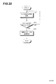
「音声メッセージ送信指示手段」は、実施形態においては、図22のステップS33などがこれに対応する。 In the embodiment, “voice message transmission instruction means” corresponds to step S33 in FIG.
「プログラム」とは、CPUにより直接実行可能なプログラムだけでなく、ソース形式のプログラム、圧縮処理がされたプログラム、暗号化されたプログラム等を含む概念である。 The “program” is a concept that includes not only a program that can be directly executed by the CPU, but also a source format program, a compressed program, an encrypted program, and the like.
1.第1の実施形態
1.1充電器の全体構成
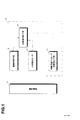
図1に、この発明の一実施形態による充電器4の全体構成を示す。装着判断手段6は、充電対象である携帯機器2が装着されたことを判断する。人体検出センサ10は、充電器4の近傍に人がいることを検出する。対象者判断手段8は、装着判断手段6の判断結果および人体検出センサ10の出力に基づいて、対象者の状態を判断する。判断内容メッセージ送信指示手段12は、携帯機器2に対し、予め登録されている登録先に宛てて、上記の判断内容を送信するように指示を与える。これを受けて、携帯機器2は、対象者の状態を、登録先にメッセージとして送信する。
1. First embodiment
1.1 Overall Configuration of Charger FIG. 1 shows an overall configuration of a
1.2外観およびハードウエア構成
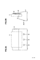
図2に、充電器4の外観を示す。図2Aが正面図、図2Bが側面図である。図2Bに示すように、この充電器4は、中央付近に携帯機器であるスマートフォン9を装着するための凹部20が設けられている。凹部20の後方には、スマートフォン9とほぼ同じ高さの後壁22が設けられている。後壁22の内部には、充電のためのコイル24が設けられている。
1.2 Appearance and Hardware Configuration FIG. 2 shows the appearance of the
充電器4の前面には、赤外線センサ28が設けられている。この赤外線センサ28によって、人体の接近を検出することができる。さらに、告知を行うためのスピーカ30、周囲の明るさを検知するための光センサ32が設けられている。充電器4の内部には、制御回路(図示せず)が設けられている。
An
図3に、制御回路のハードウエア構成を示す。CPU40には、メモリ42、スピーカ30、光センサ32、不揮発性メモリ44、赤外センサ28、近距離通信回路29、充電制御回路50が接続されている。近距離通信回路29は、たとえば、ブルーツース規格による通信回路であって、スマートフォン9との通信を行うためのものである。不揮発性メモリ44には、オペレーティングシステム46、制御プログラム48が記録されている。制御プログラム48は、オペレーティングシステム46と協働してその機能を発揮するものである。
FIG. 3 shows the hardware configuration of the control circuit. A
充電制御回路50は、充電器4に装着されたスマートフォン9に対する充電を制御する回路である。
The charging
図4に、充電のための回路構成を示す。充電器4の発振回路54は、高周波を発振して出力する。インバータ回路52は、発振回路54からの高周波に応じて、電源をスイッチングしてコイル24に与える。
FIG. 4 shows a circuit configuration for charging. The
スマートフォン9が充電器4に装着されると、内蔵されているコイル7と充電器4のコイル24が電磁結合する。これにより、コイル24の高周波電圧が、コイル7に伝達される。スマートフォン9の全波整流回路5はこれを整流し、蓄電池3に与える。このようにして、蓄電池3が充電される。
When the
なお、充電器4の充電制御回路50は、充電の開始や停止を制御するものである。さらに、充電制御回路50は、スマートフォン9と通信する機能も有している。つまり、コイル24に与える高周波を、信号によって変調する。スマートフォン9側においては、電磁結合によって伝送された高周波から信号を復調する。同様にして、スマートフォン9から充電器4に対して信号を送ることもできる。充電制御回路50は、常に所定時間間隔で、ID問い合わせ信号を送信している。スマートフォン9が装着されると、スマートフォン9がこのID問い合わせ信号を受信する。ID問い合わせ信号を受信したスマートフォン9は、自らのIDを充電器4に返信する。したがって、ID問い合わせ信号に対する返信の有無により、スマートフォン9が装着されているかどうかを判断できる。
The charging
1.3制御プログラムの処理
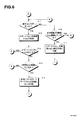
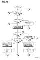
図5、図6に、制御プログラム48のフローチャートを示す。CPU40は、光センサ32の出力を取得し、周囲の光度が所定値以上であるかどうかを判断する(ステップS1)。所定値に達していなければ、就寝中であると判断する(ステップS5)。日中は照明器具を付けていなくても所定値以上の光度に達するであろうし、夜間は就寝していなければ照明器具を付けていると思われるからである。なお、この実施形態では、独居老人(対象者)は、原則として夜は自宅で就寝することを前提としている。
1.3 Processing of Control Program FIGS. 5 and 6 are flowcharts of the
周囲の光度が所定値以上であれば、CPU40は、充電器4にスマートフォン9が装着(載置)されているかどうかを判断する(ステップS2)。スマートフォン9が装着されているかどうかは、充電制御回路50に問い合わせることによって知ることができる。スマートフォン9が装着されていれば、次に、赤外センサ28がオンであるかどうかを判断する(ステップS3)。つまり、周囲に人がいるかどうかを判断する。赤外センサがオフであれば、CPU40は、このオフ状態が8時間(所定時間)以上継続しているかどうかを判断する(ステップS6)。オフ状態が8時間継続していなければ、ステップS1に戻る。
If the ambient light intensity is greater than or equal to a predetermined value, the
オフ状態が8時間以上継続していた場合、CPU40は、独居老人は在宅しているが8時間以上充電器4から離れていると判断する(ステップS7)。CPU40は、この判断内容を、予め登録してある登録先にメッセージとして送信するように、スマートフォン9に送信指令を与える(ステップS8)。この送信指令は、近距離通信回路29を介して、スマートフォン9に与えられる。
When the off state has continued for 8 hours or more, the
この指令は、スマートフォン9のメーラー(メール送受信プログラム)に与えられる。メーラーは、予め、緊急連絡先として登録されている登録先(複数であってもよい)に対し、上記判断内容を内容とするメールを送信する。
This command is given to the mailer (email transmission / reception program) of the
したがって、登録先として独居老人の親族などを設定しておくことにより、在宅しているにもかかわらず、充電器4に8時間以上(所定時間以上)近づいていないことがメールとして報告される。
Therefore, by setting a relative of the elderly living alone as a registration destination, it is reported as an e-mail that the
ステップS3において、赤外センサがオンであれば(つまり人が検出されていれば)、CPU40は、オン状態が8時間以上継続しているかどうかを判断する(ステップS4)。継続していなければ、ステップS1に戻る。
In step S3, if the infrared sensor is on (that is, if a person is detected),
オン状態が8時間以上継続していれば、CPU40は、独居老人は在宅しており8時間以上充電器4から離れられない危険な状態(あるいは意識的に離れない状態)であると判断する(ステップS9)。CPU40は、この判断内容を、予め登録してある登録先にメッセージとして送信するように、スマートフォン9に送信指令を与える(ステップS10)。これにより、登録先に対して、判断内容を通知することができる。
If the ON state continues for 8 hours or more, the
以上のようにして、在宅を前提として、充電器4の前から長時間離れない異常な状態や充電器4に長時間近づかない異常な状態を、メッセージとして登録者に知らせることができる。
As described above, it is possible to notify the registrant as a message of an abnormal state that does not leave the
ステップS2において、スマートフォン9が装着されていない場合、CPU40は、赤外センサ28がオンであるかどうかを判断する(図6、ステップS11)。赤外センサ28がオンであれば人が近くにいるので、CPU40は、スピーカ30からスマートフォン9を充電器4に装着するように音声出力を行う(ステップS12)。
In step S2, if the
CPU40は、続いて、スマートフォン9が充電器4に装着されたかどうかを判断する(ステップS13)。装着が確認できた場合、図5のステップS3に進む。装着が確認できない場合、CPU40は、ステップS4においてNOの判断をしてから1時間以上継続してスマートフォン9が装着されていないかを判断する(ステップS14)。1時間以上継続してスマートフォン9が装着されていなければ、CPU40は、在宅しているがスマートフォン9が装着されていないと判断する(ステップS15)。たとえば、異常な事態だが、充電器4にスマートフォン9が装着されていないため、通信相手にメールができない場合などがこれに該当する。そして、ステップS1に進む。
Subsequently, the
ステップS11において、赤外センサ28がオフであれば、CPU40は、その状態が8時間以上継続しているかどうかを判断する(ステップS16)。オフ状態が8時間以上継続していれば、CPU40は、スマートフォン9、独居老人ともに所在不明であると判断する(ステップS17)。そして、ステップS1に進む。
If the
この実施形態では、スマートフォン9を介して、登録者にメッセージを送信するようにしているので、ステップS15、S17の場合には、登録者にメッセージを送信することができない。しかし、この判断内容を、充電器4の不揮発性メモリ44に時刻とともに記録することで、必要なときにこれを他の装置で読み出して状況を見ることができる。たとえば、独居老人が家で倒れていたり、行方不明であった場合に、その時の状況を知ることができる。
In this embodiment, since a message is transmitted to the registrant via the
1.4その他の実施形態
(1)上記実施形態では、独居老人(対象者)は、原則として夜は自宅で就寝することを前提としている。しかし、ベッドに人体検出センサを設けておき、就寝中かどうかを判断するようにしてもよい。また、予め就寝時間を充電器4に登録しておき、その時間内は就寝しているものと推定してもよい。
1.4 Other embodiments
(1) In the embodiment described above, it is assumed that an elderly person living alone (subject) goes to bed at home in principle. However, a human body detection sensor may be provided on the bed to determine whether or not the person is sleeping. Alternatively, the bedtime may be registered in the
(2)上記実施形態では、ブルーツースなどの近距離通信回路29によって、スマートフォン9に対してのメッセージ送信指令などを送るようにしている。しかし、これに代えて、図4に示す充電回路の電磁結合を利用して、メッセージ送信指令を伝達するようにしてもよい。
(2) In the above embodiment, a message transmission command or the like is sent to the
(3)上記実施形態では、スマートフォン9のメーラーを用いてメッセージを送信するようにしている。しかし、メーラー以外のライン(商標)などのメッセージ通信プログラムを用いてもよい。
(3) In the above embodiment, the message is transmitted using the mailer of the
(4)上記実施形態では、スマートフォン9のメーラーを用いてメッセージを送信するようにしている。しかし、充電器4の側に通信回路を設け、メーラーなどのメッセージ通信プログラムをインストールして、充電器4から直接、登録先に対してメッセージを送信するようにしてもよい。このようにすれば、図6のステップS15、S17の判断内容についても、登録者にメッセージとして送信することができる。この場合、登録先は充電器4の側に記録しておくことが好ましい。
(4) In the above embodiment, the message is transmitted using the mailer of the
(5)上記実施形態では、充電のための電磁結合を介した通信にて、スマートフォン9が装着されているかどうかを判断している。しかし、充電器4にセンサ(たとえば、マイクロスイッチ)を設け、スマートフォン9が装着されたことを検出するようにしてもよい。
(5) In the above embodiment, it is determined whether or not the
(6)上記実施形態では、ステップS15やステップS17において、独居老人に対して、さらなる積極的な働きかけは行っていない。しかし、近距離通信回路29を介して、スマートフォン9のスピーカから充電器にセットして下さいとの旨の音声を出力させるようにしてもよい。
(6) In the above embodiment, no further positive action is given to the elderly living alone in step S15 or step S17. However, you may make it output the voice to the effect of setting to the charger from the speaker of the
(7)上記実施形態では、通信機能を有する携帯機器としてスマートフォン9を例として説明した。しかし、携帯電話、携帯情報端末、タブレットコンピュータ、携帯ゲーム機、カメラなどにも適用することができる。
(7) In the said embodiment, the
(8)上記実施形態では、非接触式の充電回路について説明したが、接触式の充電回路についても同様に適用することができる。 (8) Although the contactless charging circuit has been described in the above embodiment, the invention can be similarly applied to a contact charging circuit.
(9)上記実施形態では、赤外センサによって人を検出するようにしている。しかし、静電センサ、光電センサなどを用いてもよい。 (9) In the above embodiment, a person is detected by an infrared sensor. However, an electrostatic sensor, a photoelectric sensor, or the like may be used.
(10)上記実施形態では、対象者として独居老人を例としてあげた。しかし、老人でなくとも一人住まいの人を対象とすることができる。また、一人住まいでない人も対象とすることができる。 (10) In the above embodiment, an elderly person living alone was taken as an example of the subject. However, even non-elderly people can be targeted. In addition, people who do not live alone can also be targeted.
(11)上記実施形態では、対象者判断手段8を設け、その判断内容を、判断内容メッセージ送信指示手段12の指示により、携帯機器2から送信するようにしている。
(11) In the above embodiment, the subject determination means 8 is provided, and the determination content is transmitted from the
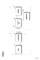
しかし、図7に示すように、人体検知センサ10の出力(人の有無)および装着判断手段6の判断結果(装着の有無)を、状況送信指示手段100の指示により、携帯機器2から送信するようにしてもよい。状況送信指示手段100による送信指示タイミングは、所定の条件が整った場合(たとえば、人を検出したとき、人の検出がなくなったとき、携帯機器が装着されたとき、携帯機器が非装着となったとき等)や、所定時間間隔(たとえば、1時間ごと)で行うことができる。また、携帯機器から状況送信依頼を受けた場合(携帯機器の操作により状況送信依頼が入力された場合や携帯機器に対して状況送信依頼を求めるメールなどが着信した場合など)、これに応じて送信するようにしてもよい。
However, as shown in FIG. 7, the output of the human body detection sensor 10 (the presence / absence of a person) and the determination result of the attachment determination means 6 (presence / absence of attachment) are transmitted from the
なお、図7では、人体検知センサ10の出力および装着判断手段6の判断結果の双方を送信するようにしているが、いずれか一方だけでもよい。
In FIG. 7, both the output of the human
(12)上記実施形態における図1の各機能(手段およびセンサ)の一部または全部は、携帯機器2の側に設けるようにしてもよい。
(12) Part or all of the functions (means and sensors) in FIG. 1 in the above embodiment may be provided on the
(13)上記実施形態において、充電器4にカメラボタンを設けるようにしてもよい。このボタンが押下されると、充電器4はスマートフォン9に対して、カメラによる撮像を行い、予め定められた登録先にメール添付して送信するように指示を行う。
(13) In the above embodiment, the
(14)また、遠隔のスマートフォンから、スマートフォン9に対して、上記の指令を与えるようにしてもよい。これにより、独居老人の居宅の様子が自動的に撮像され、当該遠隔のスマートフォンに対して送信される。
(14) The above-mentioned command may be given to the
(15)上記の実施形態および各変形例は、その本質に反しない限り、他の実施形態にも適用することができる。
(15) The above embodiment and each modified example can be applied to other embodiments as long as they do not contradict the essence.
2.第2の実施形態
2.1全体構成
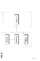
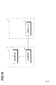
図8に、第2の実施形態による携帯装置2と充電器4の全体構成を示す。この実施形態では、装着判断手段6、対象者判断手段8、判断内容メッセージ送信手段102を、携帯装置2の側に設け、充電器4には人体検出センサ10を設けている。
2. Second embodiment
2.1 Overall Configuration FIG. 8 shows the overall configuration of the
装着判断手段6は、携帯機器2が充電器4に装着されているか否かを判断する。人体検出センサ10は、充電器4の近傍に人がいることを検出する。対象者判断手段8は、充電器4から取得した人体検出センサ10の出力と、装着判断手段6の判断結果とに基づいて、対象者の状態を判断する。判断内容メッセージ送信手段102は、予め登録されている登録先に対し、上記の判断内容をメッセージとして送信する。
The attachment determination means 6 determines whether or not the
2.2外観およびハードウエア構成
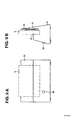
図9に、充電器4の外観を示す。図9Aが正面図、図9Bが側面図である。充電器4の外観は、第1の実施形態における図2と同様である。ただし、図9Aに示すように、スピーカ30と光センサ32を設ける必要はない。この実施形態では、人体を検出するための赤外線センサ28を設けている。
2.2 Appearance and Hardware Configuration FIG. 9 shows the appearance of the
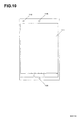
図10に、スマートフォン9の外観を示す。中央部に表示と入力のためのタッチスクリーン114が設けられている。下部にはマイク126、上部にはスピーカ116、光センサ118が設けられている。
FIG. 10 shows the appearance of the
図11に、充電器4の制御回路のハードウエア構成を示す。CPU40には、メモリ42、不揮発性メモリ44、赤外センサ28、近距離通信回路29、充電制御回路50が接続されている。その基本的構成は、図3と同様である。
FIG. 11 shows a hardware configuration of the control circuit of the
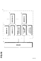
図12に、スマートフォン9のハードウエア構成を示す。CPU110には、メモリ112、タッチスクリーン114、スピーカ116、光センサ118、不揮発性メモリ120、通信回路122、近距離通信回路124、マイク126が接続されている。なお、スマートフォンとしての通話回路などは省略している。
FIG. 12 shows a hardware configuration of the
光センサ118は、周囲の明るさを検出するためのものである。通信回路122は、インターネットなどに接続するためのものである。近距離通信回路124は、たとえば、ブルーツース規格による通信回路であって、充電器4との通信を行うためのものである。
The
不揮発性メモリ120には、オペレーティングシステム128、スマートフォンとしての基本機能を実現するための基本機能プログラム130、携帯端末プログラムである制御アプリ132が記録されている。基本機能プログラム130および制御アプリ132は、オペレーティングシステム128と協働してその機能を発揮するものである。
The
2.3制御アプリ132の処理
第一の実施形態では、判断処理を充電器4の側において行っていたが、この実施形態では、スマートフォン9の側にて行うようにしている。
2.3 Processing of
図13、図14に、スマートフォン9の制御アプリ132のフローチャートを示す。この制御アプリ132は、スマートフォン9の電源投入時に、自動的に起動するように構成されている。なお、制御アプリ132が起動している場合であっても、オペレーティングシステム128の制御により、スマートフォンとしての機能(電話着信、通話など)は、割り込み処理によって実行されるようになっている。
FIGS. 13 and 14 show flowcharts of the
CPU110は、まず、スマートフォン9が充電器4にセットされているかどうかを判断する(ステップS2)。この実施形態では、スマートフォン9の光センサ118を用いているので、充電器4にセットされた状態でないと、対象者の居宅の照度を得ることができない。したがって、光センサ118の照度判定をする前に、スマートフォン9が充電器4にセットされているかどうかを判断するようにしている。
CPU110 judges first whether the
充電器4にセットされているかどうかは、外部からの電力供給があるかどうか等によって検出することができる。
Whether or not the
充電器4にセットされていれば、CPU110は、光センサ118の出力を取得し、周囲の光度が所定値以上であるかどうかを判断する(ステップS1)。所定値に達していなければ、就寝中であると判断する(ステップS5)。
If it is set in the
周囲の光度が所定値以上であれば、CPU110は、近距離通信回路124によって、充電器4から赤外センサ28の出力を取得する(ステップS3a)。そして、充電器4の赤外センサ28がオンであるかどうかを判断する(ステップS3b)。つまり、周囲に人がいるかどうかを判断する。赤外センサがオフであれば、CPU110は、このオフ状態が8時間(所定時間)以上継続しているかどうかを判断する(ステップS6)。オフ状態が8時間継続していなければ、ステップS2に戻る。
If the ambient luminous intensity is equal to or greater than the predetermined value, the
オフ状態が8時間以上継続していた場合、CPU110は、独居老人は在宅しているが8時間以上充電器4から離れていると判断する(ステップS7)。CPU110は、この判断内容を、予め登録してある登録先にメッセージとして送信する(ステップS8)。CPU110は、基本機能プログラム130中のメーラー(メール送受信プログラム)により、緊急連絡先として登録されている登録先(複数であってもよい)に対し、上記判断内容を内容とするメールを送信する。
When the off state has continued for 8 hours or more, the
ステップS3bにおいて、赤外センサがオンであれば(つまり人が検出されていれば)、CPU110は、オン状態が8時間以上継続しているかどうかを判断する(ステップS4)。継続していなければ、ステップS2に戻る。
In step S3b, if the infrared sensor is on (that is, if a person is detected),
オン状態が8時間以上継続していれば、CPU110は、独居老人は在宅しており8時間以上充電器4から離れられない危険な状態(あるいは意識的に離れない状態)であると判断する(ステップS9)。CPU110は、この判断内容を、予め登録してある登録先にメッセージとして送信する(ステップS10)。これにより、登録先に対して、判断内容を通知することができる。
If the ON state continues for 8 hours or more, the
以上のようにして、在宅を前提として、充電器4の前から長時間離れない異常な状態や充電器4に長時間近づかない異常な状態を、メッセージとして登録者に知らせることができる。
As described above, it is possible to notify the registrant as a message of an abnormal state that does not leave the
ステップS2において、スマートフォン9が装着されていない場合、CPU110は、充電器4と通信可能であるかどうかを判断する(ステップS11a)。たとえば、ブルーツースにて通信を行う場合には、スマートフォン9が充電器4にセットされていなくとも、スマートフォン9が近くにあれば通信が可能である。
In step S2, when the
ステップS11aにおいて、充電器4との通信が可能であれば、充電器4から赤外センサの出力を取得する(ステップS11b)。赤外センサ28がオンであれば人が近くにいるので、CPU110は、スピーカ116からスマートフォン9を充電器4に装着するように音声出力を行う(ステップS12)。
If communication with the
CPU110は、続いて、スマートフォン9が充電器4に装着されたかどうかを判断する(ステップS13)。装着が確認できた場合、図13のステップS3aに進む。装着が確認できない場合、CPU110は、ステップS4においてNOの判断をしてから1時間以上継続してスマートフォン9が装着されていないかを判断する(ステップS14)。1時間以上継続してスマートフォン9が装着されていなければ、CPU110は、在宅しているがスマートフォン9が装着されていないと判断する(ステップS15)。そして、ステップS1に進む。
Subsequently, the
ステップS11cにおいて、赤外センサ28がオフであれば、CPU110は、その状態が8時間以上継続しているかどうかを判断する(ステップS16)。オフ状態が8時間以上継続していれば、CPU110は、スマートフォン9は充電器4の近くにあるが、対象者が所在不明であると判断する(ステップS17)。そして、ステップS1に進む。
In step S11c, if the
この実施形態では、スマートフォン9によって、登録者にメッセージを送信するようにしているので、ステップS15、S17の場合にも、登録者にメッセージを送信することができる。
In this embodiment, since the
2.4その他の実施形態
(1)上記実施形態では、独居老人(対象者)は、原則として夜は自宅で就寝することを前提としている。しかし、ベッドに人体検出センサを設けておき、就寝中かどうかを判断するようにしてもよい。また、予め就寝時間をスマートフォン9に登録しておき、その時間内は就寝しているものと推定してもよい。
2.4 Other embodiments
(1) In the embodiment described above, it is assumed that an elderly person living alone (subject) goes to bed at home in principle. However, a human body detection sensor may be provided on the bed to determine whether or not the person is sleeping. Alternatively, the bedtime may be registered in advance in the
(2)上記実施形態では、ブルーツースなどの近距離通信回路29によって、スマートフォン9に対しての赤外センサ28の出力をなどを送るようにしている。しかし、これに代えて、図4に示す充電回路の電磁結合を利用して伝達するようにしてもよい。
(2) In the above embodiment, the output of the
(3)上記実施形態では、スマートフォン9のメーラーを用いてメッセージを送信するようにしている。しかし、メーラー以外のライン(商標)などのメッセージ通信プログラムを用いてもよい。
(3) In the above embodiment, the message is transmitted using the mailer of the
(4)上記実施形態では、外部からの電源供給の有無によって、充電器4への装着を判断している。しかし、第一の実施形態において示したように、充電器4によるスマートフォン9の装着有無の判断を、近距離通信回路29にて受けるようにしてもよい。
(4) In the above embodiment, the attachment to the
(5)上記実施形態では、ステップS15やステップS17において、独居老人に対して、さらなる積極的な働きかけは行っていない。しかし、スピーカ116から充電器にセットして下さいとの旨の音声を出力させるようにしてもよい。
(5) In the above embodiment, no further positive action is given to the elderly living alone in step S15 or step S17. However, a sound indicating that the
(6)上記実施形態では、通信機能を有する携帯機器としてスマートフォン9を例として説明した。しかし、携帯電話、携帯情報端末、タブレットコンピュータ、携帯ゲーム機、カメラなどにも適用することができる。
(6) In the said embodiment, the
(7)上記実施形態では、非接触式の充電回路について説明したが、接触式の充電回路についても同様に適用することができる。 (7) Although the contactless charging circuit has been described in the above embodiment, the invention can be similarly applied to a contact charging circuit.
(8)上記実施形態では、赤外センサ28によって人を検出するようにしている。しかし、静電センサ、光電センサなどを用いてもよい。
(8) In the above embodiment, the
(9)上記実施形態では、対象者として独居老人を例としてあげた。しかし、老人でなくとも一人住まいの人を対象とすることができる。また、一人住まいでない人も対象とすることができる。 (9) In the above-described embodiment, an elderly person living alone was taken as an example of the subject. However, even non-elderly people can be targeted. In addition, people who do not live alone can also be targeted.
(10)上記実施形態では、対象者判断手段8を設け、その判断内容を、判断内容メッセージ送信手段102により送信するようにしている。 (10) In the above embodiment, the target person determination means 8 is provided, and the determination content is transmitted by the determination content message transmission means 102.
しかし、図15に示すように、人体検知センサ10の出力(人の有無)および装着判断手段6の判断結果(装着の有無)を、状況送信手段104により送信するようにしてもよい。状況送信手段104による送信タイミングは、所定の条件が整った場合(たとえば、人を検出したとき、人の検出がなくなったとき、充電器に装着されたとき、充電器から取り外されたとき等)や、所定時間間隔(たとえば、1時間ごと)で行うことができる。また、状況送信依頼を受けた場合(携帯機器の操作により状況送信依頼が入力された場合や携帯機器に対して状況送信依頼を求めるメールなどが着信した場合など)、これに応じて送信するようにしてもよい。
However, as shown in FIG. 15, the output (the presence / absence of a person) of the human
なお、図15では、人体検知センサ10の出力および装着判断手段6の判断結果の双方を送信するようにしているが、いずれか一方だけでもよい。
In FIG. 15, both the output of the human
(11)上記実施形態では、人体検出センサ10を充電器4の側に設けているが、スマートフォン9の側に設けるようにしてもよい。また、装着判断手段6をスマートフォン9の側に設けているが、充電器4の側に設けるようにしてもよい。
(11) Although the human
(12)上記実施形態では、スマートフォン9の電源投入時に、制御アプリ132を自動的に起動させるようにしている。しかし、スマートフォン9を充電器4にセットした時に制御アプリ132が起動し、充電器4から取り外すと制御アプリ132が終了するようにしてもよい。このようにした場合、図13のステップS2は不要であり、図14の処理も不要となる。
(12) In the above embodiment, the
(13)上記の各処理は、スマートフォン9単独で(つまり充電器4なしで)実施することができる。この場合、スマートフォン9に人体検知センサ10を設けるか、あるいは、人体検知センサ10に関する処理を行わないようにすることができる。
(13) Each of the above processes can be performed by the
(14)上記実施形態において、スマートフォン9にカメラボタンを表示するようにしてもよい。このボタンが押下されると、スマートフォン9は、カメラによる撮像を行い、予め定められた登録先にメール添付して送信する。
(14) In the above embodiment, a camera button may be displayed on the
(15)また、遠隔のスマートフォンから、スマートフォン9に対して、上記の指令を与えるようにしてもよい。これにより、独居老人の居宅の様子が自動的に撮像され、当該遠隔のスマートフォンに対して送信される。
(15) Further, the above command may be given to the
(16)上記の実施形態および各変形例は、その本質に反しない限り、他の実施形態にも適用することができる。
(16) The above-described embodiment and each modification can be applied to other embodiments as long as they do not contradict the essence.
3.第3の実施形態
3.1充電器の全体構成
図16に、第3の実施形態による充電器4の全体構成を示す。装着判断手段6は、充電対象である携帯機器2が装着されたことを判断する。人体検出センサ10は、充電器4の近傍に人がいることを検出する。対象者判断手段8は、装着判断手段6の判断結果および人体検出センサ10の出力に基づいて、対象者の状態を判断する。判断内容メッセージ送信指示手段12は、携帯機器2に対し、予め登録されている登録先に宛てて、上記の判断内容を送信するように指示を与える。これを受けて、携帯機器2は、対象者の状態を、登録先にメッセージとして送信する。
3. Third embodiment
3.1 Overall Configuration of Charger FIG. 16 shows the overall configuration of the
メッセージ着信検知手段13は、携帯機器2にメッセージの着信があったことを検知する。着信告知手段15は、音声や光にて告知を行う機器を制御して、携帯機器2にメッセージが着信していることを知らせる。この告知を受けて、対象者からのメッセージの出力指示を受けると、メッセージ音声出力手段17は、メッセージを音声として出力する。
The message
3.2外観およびハードウエア構成
充電器4の外観および各部のハードウエア構成について、基本的な部分は第1の実施形態と同様である。ただし、この実施形態では、図17に示すように、照明付スイッチ26、27が、充電器4の前面に設けられている。この照明付スイッチ26は、メッセージの着信を知らせるとともに、メッセージの音声出力を指示するためのものである。また、照明付スイッチ27は、メッセージに対する返信を行うためのボタンである。さらに、メッセージを録音するためのマイク31が設けられている。
3.2 Appearance and Hardware Configuration The basic portion of the appearance of the
なお、メッセージに対する返信を行う機能を設けない場合には、照明付スイッチ27、マイク31は不要である。
In the case where a function for replying to a message is not provided, the illuminated
図18に、充電器4のハードウエア構成を示す。この実施形態では、照明付スイッチ26、27も、CPU40に接続されている。
FIG. 18 shows a hardware configuration of the
3.3制御プログラムの処理
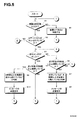
この実施形態における制御プログラム48のフローチャートを、図19〜図22に示す。図19、図20は、第1の実施形態における図5、図6と同様である。ただし、図19のステップS4においてNOの判断をした場合(つまり、独居老人(対象者)が在宅であって異常な状況でない場合)には、図21に示すような処理を行う。
3.3 Processing of Control Program A flowchart of the
CPU40は、スマートフォン9にメッセージ着信があったかどうかを確認する(ステップS21)。この実施形態では、CPU40は、近距離通信回路29によってスマートフォン9と通信し、メッセージ着信の有無を確認する。たとえば、スマートフォン9のメーラーに対し、新規着信(未読メッセージ)の有無を問い合わせる。これに対するスマートフォン9のメーラーからの回答によって、新規着信の有無を知ることができる。
CPU40 confirms whether the
なお、スマートフォン9においては、メーラーが常時起動しているように設定しておくことが好ましい。あるいは、充電器4へのセットを感知して、メーラーが立ち上がるようにしてもよい。あるいはまた、CPU40から、スマートフォン9に対して、メーラーを起動する指示を送信するようにしてもよい。
In addition, in the
メッセージ着信がなければ、CPU40は、ステップS1に進む。メッセージ着信があれば、CPU40は、赤外センサがオンであるかどうかを判断する(ステップS22)。オフであれば、CPU40は、メッセージ着信ありの判断から1時間以上継続して赤外センサがオフであるかを判断する(ステップS27)。1時間以上オフが継続していなければ、ステップS22に戻る。1時間以上オフが継続していれば、CPU40は、メッセージ着信から1時間以上充電器4から離れていると判断する。
If there is no incoming message, the
さらに、この判断内容を、予め登録してある登録先にメッセージとして送信するように、スマートフォン9に送信指令を与える(ステップS28)。これにより、登録先に対して、判断内容を通知することができる。
Furthermore, a transmission command is given to the
ステップS22において、赤外センサ28がオンであれば、CPU40は、照明付スイッチ26の照明を点灯させる(ステップS23)。これにより、独居老人は、メッセージ着信があったことを知ることができる。
If the
さらに、CPU40は、スピーカ30からメッセージが到着している旨の音声を出力する(ステップS24)。たとえば、「メッセージが届いています、点灯しているボタンを押してください」のような告知音声を出力する。
Further, the
次に、CPU40は、照明付スイッチ26が押下されたかどうかを判断する(ステップS25)。独居老人によって照明付スイッチ26が押下されると、CPU40は、照明付スイッチ26を消灯し、近距離通信回路29を介して、スマートフォン9から着信メッセージを取得する。CPU40は、取得した文字データによる着信メッセージを、音声合成し、スピーカ30から音声として出力する(ステップS26)。
Next, the
この実施形態では、予め、送信元のメールアドレスと送信元情報(氏、名、氏名、会社名、愛称など)とを対応付けて、不揮発性メモリ44に記録している(送信元情報テーブル)。CPU40は、着信メッセージを取得した際に、それに含まれる送信元のメールアドレスに基づいて、対応する上記記録された送信元情報を取得する。そして、上記着信メーセージの音声出力の前にもしくは後に、この送信元情報を音声合成して、スピーカ30から出力する。これにより、送信元が誰であるかを、容易に知ることができる。
In this embodiment, a sender's mail address and sender information (name, name, name, company name, nickname, etc.) are associated with each other and recorded in the nonvolatile memory 44 (sender information table). . When acquiring the incoming message, the
なお、送信元の個人に対応付けて、その音声の特徴を示すパラメータを予め記録しておき、このパラメータを用いて音声合成を行うことで、本人が発話しているかのような状況にすることができる。これにより、送信元が誰であるかの認識がさらに容易になる。 In addition, a parameter indicating the characteristics of the voice is recorded in advance in association with the individual of the transmission source, and the voice is synthesized using this parameter, so that the situation is as if the person is speaking. Can do. This further facilitates recognition of who the transmission source is.
なお、添付ファイルがある場合、同様にして音声合成して出力する。また、添付ファイルが音声ファイルである場合には、そのまま音声として出力する。この際、スマートフォン9は、当該着信メッセージを既読状態に変更する。その後、CPU40は、ステップS1に進む。
If there is an attached file, it is synthesized and output in the same manner. If the attached file is an audio file, it is output as audio as it is. At this time, the
上記のようにして、独居老人はメッセージの着信を知るとともに、その内容を音声として聞くことができる。 As described above, the solitary elderly person can know the arrival of the message and can hear the contents as voice.
CPU40は、ステップS25において、照明付スイッチ26が押されていない場合には、メッセージ着信ありの判断から1時間以上継続して照明付スイッチ26が押されていない(オフ)であるかを判断する(ステップS29)。1時間以上継続して照明付スイッチ26がオフであれば、CPU40は、メッセージを聞く意志がないと判断する。さらに、この判断内容を、予め登録してある登録先にメッセージとして送信するように、スマートフォン9に送信指令を与える(ステップS30)。これにより、登録先に対して、判断内容を通知することができる。
In step S25, if the illuminated
以上のようにして、登録先に対し、メッセージ着信後の独居老人の状況を知らせることができる。また、この実施形態によれば、通信環境を別途構築しなくとも、人口カバー率の高いスマートフォンを有効に活用できる。 As described above, it is possible to notify the registered destination of the situation of the elderly living alone after receiving the message. Further, according to this embodiment, a smartphone with a high population coverage rate can be effectively used without separately establishing a communication environment.
さらに、この実施形態では、メッセージに対する返信メッセージを送信する機能を設けている。ステップS26において、メッセージの音声出力が終わった際に、CPU40によって、照明付スイッチ27を点滅させ、「返信をする場合は、点灯しているボタンを押してください」というメッセージを音声出力する。独居老人によって照明付スイッチ27が押されると、CPU40は、図22の返信処理を開始する。この実施形態では、図22の返信処理は、割り込み処理によって行うようにしている。
Further, in this embodiment, a function for transmitting a reply message to the message is provided. In step S26, when the voice output of the message is finished, the
CPU40は、照明付スイッチ27が押されて返信処理を開始すると、マイク33からの音声を取得し、不揮発性メモリ44に音声ファイルとして記録する(ステップS31)。照明付きスイッチ27が押された時に、「メッセージを録音して下さい。ボタンを押している間、録音がされます」等のメッセージをスピーカ30から出すようにしてもよい。
When the illuminated
なお、CPU40は、照明付スイッチ27が押されている間は、録音を継続する。CPU40は、照明付スイッチ27が離されたか(オフになったか)どうかを判断する(ステップS32)。照明付スイッチ27が離されれば、CPU40は、記録された音声ファイルをスマートフォン9に送信するとともに、当該音声ファイルを添付メッセージとして送信するようにスマートフォン9に指示する(ステップS33)。メッセージの本文は、「返信です。音声ファイルを確認してください」などの予め定めた文言とすることが好ましい。
The
この指示においては、直前に受信した(あるいは再生した)メッセージの送信元アドレスを、送信先のアドレスとして指定する。なお、CPU40は、少なくとも直前に受信した(あるいは再生した)メッセージを、その送信元アドレスを含めて、不揮発性メモリ44に記録するようにしている。
In this instruction, the source address of the message received (or reproduced) immediately before is designated as the destination address. The
上記指示を受けたスマートフォン9は、メーラーにより、上記の音声ファイルを宛先に送信する。このようにして、メールに対する返信を行うことができる。
The
3.4その他の実施形態
(1)上記実施形態では、スマートフォン9のメーラーへの全ての新規メッセージの有無を確認するようにしている。しかし、スマートフォン9や充電器4に予め登録された特定の登録先からの新規メッセージのみを対象として、その有無を確認するようにしてもよい。
3.4 Other embodiments
(1) In the above embodiment, the presence or absence of all new messages to the mailer of the
(2)上記実施形態では、充電器4の側からスマートフォン9に対して新規メッセージの有無を問い合わせるようにしている。しかし、スマートフォン9の側から新規メッセージの到着があったときに、充電器4に対して連絡するようにしてもよい。
(2) In the above embodiment, the
(3)上記実施形態では、図19〜図22の処理を行う(並行処理する)ようにしている。しかし、図21、図22に示すメッセージ関連の処理だけを実行するようにしてもよい。また、図7や図15に示す実施形態とメッセージ関連処理を組み合わせて実施するようにしてもよい。 (3) In the above embodiment, the processing of FIGS. 19 to 22 is performed (parallel processing). However, only the message-related processing shown in FIGS. 21 and 22 may be executed. Further, the embodiment shown in FIG. 7 and FIG. 15 may be combined with the message related processing.
(4)上記実施形態では、照明付ボタン27を押している間は録音を行い、照明付ボタン27を離すとメッセージの送信を行うようにしている。しかし、照明付ボタン27を押すと、所定時間の間だけ録音が行われ、その後自動的にメッセージの送信を行うようにしてもよい。あるいは、無音状態が10秒続くと返信音声の終わりであると判断して、自動的にメッセージの送信を行うようにしてもよい。
(4) In the above embodiment, recording is performed while the illuminated
なお、充電器4にカメラを設けておき、撮像画像を画像ファイルとして、これも添付して返信するようにしてもよい。
It should be noted that a camera may be provided in the
(5)上記実施形態では、メッセージに対する返信としてメールを送信する場合を説明した。しかし、返信としてではなく、独居老人からメールを送信する場合にも適用することができる。 (5) In the above embodiment, the case where an email is transmitted as a reply to a message has been described. However, the present invention can also be applied to a case where an e-mail is sent from an elderly person living alone, not as a reply.
(6)上記実施形態では、メッセージに対する返信機能を設けるようにしている。しかし、これを設けないようにしてもよい。 (6) In the above embodiment, a reply function for a message is provided. However, this may not be provided.
(7)上記実施形態では、メッセージの着信を照明付スイッチ26によって知らせるようにしている。しかし、充電器4から近距離通信回路29を介して、スマートフォン9の画面にメッセージ着信があった旨の表示を行うようにしてもよい。
(7) In the above embodiment, the illuminated
(8)上記実施形態では、音声メッセージを充電器4に記録するようにしている。しかし、充電器4から携帯機器9に対して音声メッセージを記録する指令を与え、携帯機器9のマイクを用いて携帯機器9において記録するようにしてもよい。
(8) In the above embodiment, the voice message is recorded in the
(9)上記実施形態における図16の各機能(手段およびスピーカ、マイク、センサやスイッチなど)の一部または全部を、携帯機器2の側に設けるようにしてもよい。
(9) A part or all of each function (means and speaker, microphone, sensor, switch, etc.) in FIG. 16 in the above embodiment may be provided on the
(10)上記実施形態では、直前に受信した(再生した)メールの送信元に対して返信を行うようにしている。しかし、充電器4に「戻る」「進む」ボタンなどを設け(あるいはスマートフォン9に「戻る」「進む」ボタンなどを設け)、これを押すたびに、受信メールの履歴を遡ってあるいは進めてスマートフォン9に表示し、返信先を選択できるようにしてもよい。あるいは、スマートフォン9(または充電器4)に記録されているアドレス帳に基づいて、返信先の選択を行うようにしてもよい。 (10) In the above embodiment, a reply is made to the sender of the mail received (reproduced) immediately before. However, the “return” and “forward” buttons are provided on the charger 4 (or the “return” and “forward” buttons are provided on the smartphone 9), and each time the button is pressed, the received mail history is traced back or forward. 9 may be displayed so that a reply destination can be selected. Alternatively, the reply destination may be selected based on the address book recorded in the smartphone 9 (or the charger 4).
(11)上記の実施形態および各変形例は、その本質に反しない限り、他の実施形態にも適用することができる。
(11) The above-described embodiment and each modification can be applied to other embodiments as long as they do not contradict its essence.
4.第4の実施形態
4.1全体構成
図23に、第4の実施形態による携帯装置2と充電器4の全体構成を示す。この実施形態では、装着判断手段6、対象者判断手段8、判断内容メッセージ送信手段102、メッセージ着信検知手段13、着信告知手段15、メッセージ音声出力手段17を、携帯装置2の側に設け、充電器4には人体検出センサ10を設けている。
4). Fourth embodiment
4.1 Overall Configuration FIG. 23 shows the overall configuration of the
装着判断手段6は、携帯機器2が充電器4に装着されたことを判断する。人体検出センサ10は、充電器4の近傍に人がいることを検出する。対象者判断手段8は、装着判断手段6の判断結果および人体検出センサ10の出力に基づいて、対象者の状態を判断する。判断内容メッセージ送信手段102は、予め登録されている登録先に対し、上記の判断内容を送信する。
The
メッセージ着信検知手段13は、メッセージの着信があったことを検知する。着信告知手段15は、音や画面にて、携帯機器2にメッセージが着信していることを知らせる。この告知を受けて、対象者からのメッセージの出力指示を受けると、メッセージ音声出力手段17は、メッセージを音声として出力する。
Message arrival detection means 13 detects that a message has arrived. The incoming call notification means 15 notifies the
4.2外観およびハードウエア構成
この実施形態における充電器4、スマートフォン9の外観およびハードウエア構成は、図9〜12と同様である。
4.2 Appearance and Hardware Configuration The appearance and hardware configuration of the
4.3制御アプリ132の処理
第三の実施形態では、主要な処理を充電器4の側において行っていたが、この実施形態では、スマートフォン9の側にて行うようにしている。
4.3 Processing of
この実施形態における制御アプリ132のフローチャートを、図24〜図27に示す。この制御アプリ132は、スマートフォンの電源投入時(あるいは充電器4にセットした時に)に、自動的に起動するように構成されている。なお、制御アプリ132が起動している場合であっても、オペレーティングシステム128の制御により、スマートフォンとしての機能(電話着信、通話など)は、割り込み処理によって実行されるようになっている。
The flowchart of the
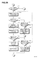
図24、図25は、第二の実施形態における図13、図14と同様である。ただし、図24のステップS4においてNOの判断をした場合(つまり、独居老人(対象者)が在宅であって異常な状況でない場合)には、図26に示すような処理を行う。 24 and 25 are the same as FIGS. 13 and 14 in the second embodiment. However, if NO is determined in step S4 in FIG. 24 (that is, if the solitary elderly person (target person) is at home and is not in an abnormal situation), the process shown in FIG. 26 is performed.
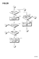
CPU110は、スマートフォン9にメッセージ着信があったかどうかを確認する(ステップS21)。この実施形態では、CPU110は、メーラー(基本機能プログラム130の一機能)に対し、新規着信(未読メッセージ)の有無を問い合わせる。これに対するメーラーからの回答によって、新規着信の有無を知ることができる。あるいは、メーラーに新規着信があった場合、フラグを立てるようにしておき、CPU110がそのフラグを確認することで、新規着信の有無を判断するようにしてもよい。
CPU110 confirms whether the
なお、スマートフォン9においては、メーラーが常時起動しているように設定しておくことが好ましい。あるいは、充電器4へのセットを感知して、メーラーが立ち上がるようにしてもよい。
In addition, in the
メッセージ着信がなければ、CPU110は、ステップS2に進む。メッセージ着信があれば、CPU110は、充電器4から赤外センサ28の出力を取得する(ステップS22a)。次に、赤外センサがオンであるかどうかを判断する(ステップS22b)。オフであれば、CPU110は、メッセージ着信ありの判断から1時間以上継続して赤外センサがオフであるかを判断する(ステップS27)。1時間以上オフが継続していなければ、ステップS22aに戻る。1時間以上オフが継続していれば、CPU110は、対象者がメッセージ着信から1時間以上充電器4から離れていると判断する。
If there is no incoming message,
さらに、この判断内容を、メーラーによって予め登録してある登録先にメッセージとして送信する(ステップS28)。これにより、登録先に対して、判断内容を通知することができる。 Further, this determination content is transmitted as a message to a registration destination registered in advance by the mailer (step S28). Thereby, the determination content can be notified to the registration destination.
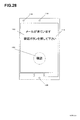
ステップS22において、赤外センサ28がオンであれば、CPU110は、着信告知およびメッセージ確認ボタンを、タッチスクリーン114に表示する(ステップS23)。図28に、その表示例を示す。着信告知150と確認ボタン152が表示されている。独居老人は、着信告知150によりメッセージ着信があったことを知ることができる。
If the
さらに、CPU110は、スピーカ116からメッセージが到着している旨の音声を出力する(ステップS24)。たとえば、「メッセージが届いています、画面の確認ボタンを押してください」のような告知音声を出力する。
Further,
次に、CPU110は、確認ボタン152が押下されたかどうかを判断する(ステップS25)。独居老人によって確認ボタン152が押下されると、CPU110は、着信告知150、確認ボタン152の表示を止め、着信メッセージを取得する。CPU110は、取得した文字データによる着信メッセージを、音声合成し、スピーカ116から音声として出力する(ステップS26)。
Next, the
この実施形態では、予め、送信元のメールアドレスと送信元情報(氏、名、氏名、会社名、愛称など)とを対応付けて、不揮発性メモリ120に記録している(送信元情報テーブル)。この送信元情報テーブルは、メーラーのアドレス帳を利用することができる。CPU110は、着信メッセージを取得した際に、それに含まれる送信元のメールアドレスに基づいて、対応する上記記録された送信元情報を取得する。そして、上記着信メーセージの音声出力の前にもしくは後に、この送信元情報を音声合成して、スピーカ116から出力する。これにより、送信元が誰であるかを、容易に知ることができる。
In this embodiment, the sender's email address and sender information (name, name, name, company name, nickname, etc.) are associated with each other and recorded in the nonvolatile memory 120 (sender information table). . This sender information table can use the mailer's address book. When the
なお、送信元の個人に対応付けて、その音声の特徴を示すパラメータを予め記録しておき、このパラメータを用いて音声合成を行うことで、本人が発話しているかのような状況にすることができる。これにより、送信元が誰であるかの認識がさらに容易になる。 In addition, a parameter indicating the characteristics of the voice is recorded in advance in association with the individual of the transmission source, and the voice is synthesized using this parameter, so that the situation is as if the person is speaking. Can do. This further facilitates recognition of who the transmission source is.
なお、添付ファイルがある場合、同様にして音声合成して出力する。また、添付ファイルが音声ファイルである場合には、そのまま音声として出力する。この際、CPU110は、メーラーを制御して当該着信メッセージを既読状態に変更する。その後、CPU110は、ステップS1に進む。
If there is an attached file, it is synthesized and output in the same manner. If the attached file is an audio file, it is output as audio as it is. At this time, the
上記のようにして、独居老人はメッセージの着信を知るとともに、その内容を音声として聞くことができる。 As described above, the solitary elderly person can know the arrival of the message and can hear the contents as voice.
CPU110は、ステップS25において、確認ボタン152が押されていない場合には、メッセージ着信ありの判断から1時間以上継続して確認ボタン152が押されていない(オフ)であるかを判断する(ステップS29)。1時間以上継続して確認ボタン152がオフであれば、CPU110は、メッセージを聞く意志がないと判断する。さらに、この判断内容を、予め登録してある登録先にメッセージとして送信する(ステップS30)。これにより、登録先に対して、判断内容を通知することができる。
If the
以上のようにして、登録先に対し、メッセージ着信後の独居老人の状況を知らせることができる。また、この実施形態によれば、通信環境を別途構築しなくとも、人口カバー率の高いスマートフォンを有効に活用できる。 As described above, it is possible to notify the registered destination of the situation of the elderly living alone after receiving the message. Further, according to this embodiment, a smartphone with a high population coverage rate can be effectively used without separately establishing a communication environment.
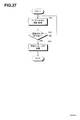
さらに、この実施形態では、メッセージに対する返信メッセージを送信する機能を設けている。ステップS26において、メッセージの音声出力が終わった際に、CPU110によって、「返信をする場合は、画面のボタンを押してください」という音声を出力する。これとともに、CPU110は、図29に示すように、返信のためのメッセージ160と、返信ボタン162をタッチスクリーン114に表示する(ステップS35)。
Further, in this embodiment, a function for transmitting a reply message to the message is provided. In step S26, when the voice output of the message is finished, the
独居老人によって返信ボタン162が押されると、CPU110は、図27の返信処理を開始する。この実施形態では、図27の返信処理は、割り込み処理によって行うようにしている。
When the
CPU110は、返信ボタン162が押されて返信処理を開始すると、マイク126からの音声を取得し、不揮発性メモリ120に音声ファイルとして記録する(ステップS31)。返信ボタン162が押された時に、「メッセージを録音して下さい。ボタンを押している間、録音がされます」等のメッセージをスピーカ116から出すようにしてもよい。
When the
なお、CPU110は、返信ボタン162が押されている間は、録音を継続する。CPU110は、返信ボタン162が離されたか(オフになったか)どうかを判断する(ステップS32)。返信ボタン162が離されれば、CPU110は、メーラーにより記録された音声ファイルを添付したメッセージとして送信する。メッセージの本文は、「返信です。音声ファイルを確認してください」などの予め定めた文言とすることが好ましい。
Note that the
この時、直前に受信した(あるいは再生した)メッセージの送信元アドレスを、送信先のアドレスとして指定する。なお、CPU110は、少なくとも直前に受信した(あるいは再生した)メッセージを、その送信元アドレスを含めて、不揮発性メモリ44に記録するようにしている。あるいは、メーラーから取得するようにしている。このようにして、メールに対する返信を行うことができる。
At this time, the source address of the message received (or reproduced) immediately before is designated as the destination address. Note that the
4.4その他の実施形態
(1)上記実施形態では、スマートフォン9のメーラーへの全ての新規メッセージの有無を確認するようにしている。しかし、スマートフォン9に予め登録された特定の登録先からの新規メッセージのみを対象として、その有無を確認するようにしてもよい。
4.4 Other embodiments
(1) In the above embodiment, the presence or absence of all new messages to the mailer of the
(3)上記実施形態では、図24、図25、図26、図27の処理を行う(並行処理する)ようにしている。しかし、図26、図27に示すメッセージ関連の処理だけを実行するようにしてもよい。また、図7や図15に示す実施形態とメッセージ関連処理を組み合わせて実施するようにしてもよい。 (3) In the above embodiment, the processing of FIGS. 24, 25, 26, and 27 is performed (parallel processing). However, only the message-related processing shown in FIGS. 26 and 27 may be executed. Further, the embodiment shown in FIG. 7 and FIG. 15 may be combined with the message related processing.
(4)上記実施形態では、返信ボタン162を押している間は録音を行い、返信ボタン162を離すとメッセージの送信を行うようにしている。しかし、返信ボタン162を押すと、所定時間の間だけ録音が行われ、その後自動的にメッセージの送信を行うようにしてもよい。あるいは、無音状態が10秒続くと返信音声の終わりであると判断して自動的にメッセージの送信を行うようにしてもよい。
(4) In the above embodiment, recording is performed while the
上記返信メッセージ送信の際、スマートフォン9のカメラ(図示せず)によって撮像を行い、撮像画像を画像ファイルとして、これも添付して返信するようにしてもよい。
When the reply message is transmitted, an image may be taken by a camera (not shown) of the
(5)上記実施形態では、メッセージに対する返信としてメールを送信する場合を説明した。しかし、返信としてではなく、独居老人からメールを送信する場合にも適用することができる。 (5) In the above embodiment, the case where an email is transmitted as a reply to a message has been described. However, the present invention can also be applied to a case where an e-mail is sent from an elderly person living alone, not as a reply.
(6)上記実施形態では、メッセージに対する返信機能を設けるようにしている。しかし、これを設けないようにしてもよい。 (6) In the above embodiment, a reply function for a message is provided. However, this may not be provided.
(7)上記実施形態では、確認ボタン152、返信ボタン162をスマートフォン9の画面に表示するようにしている。しかし、これらボタンを、第三の実施形態のように、照明付スイッチとして充電器4の側に設けるようにしてもよい。
(7) In the above embodiment, the
(8)上記実施形態における図23の各機能(手段およびスピーカ、マイク、センサやスイッチなど)の一部または全部を、充電器4の側に設けるようにしてもよい。
(8) A part or all of the functions (means and speaker, microphone, sensor, switch, etc.) in FIG. 23 in the above embodiment may be provided on the
(9)上記実施形態では、直前に受信した(再生した)メールの送信元に対して返信を行うようにしている。しかし、スマートフォン9に「戻る」「進む」ボタンを表示し(あるいは充電器4に「戻る」「進む」ボタンを設け)、これを押すたびに、受信メールの履歴を遡ってあるいは進めてスマートフォン9に表示し、返信先を選択できるようにしてもよい。あるいは、スマートフォン9(または充電器4)に記録されているアドレス帳に基づいて、返信先の選択を行うようにしてもよい。 (9) In the above embodiment, a reply is made to the sender of the mail received (reproduced) immediately before. However, the “return” and “forward” buttons are displayed on the smartphone 9 (or the “return” and “forward” buttons are provided on the charger 4), and each time the button is pressed, the history of the received mail is traced back or forward. May be displayed so that a reply destination can be selected. Alternatively, the reply destination may be selected based on the address book recorded in the smartphone 9 (or the charger 4).
(10)上記の各処理は、スマートフォン9単独で(つまり充電器4なしで)実施することができる。この場合、スマートフォン9に人体検知センサ10を設けるか、あるいは、人体検知センサ10に関する処理を行わないようにすることもできる。
(10) Each of the above processes can be performed by the
(11)上記の実施形態および各変形例は、その本質に反しない限り、他の実施形態にも適用することができる。 (11) The above-described embodiment and each modification can be applied to other embodiments as long as they do not contradict its essence.
Claims (68)
携帯機器が装着されているかどうかを判断する装着判断手段と、
人体を検出する人体検出センサと、
前記対象者について、少なくとも下記(a)または(b)の判断を行う対象者判断手段と、
を備えた充電器。
(a)装着判断手段によって携帯機器が装着されていると判断された状態で、人体検出センサによる人体検出が所定時間継続してなされていない場合に、対象者が居宅にいるにもかかわらず、対象者が充電器に所定時間近づいていないとする第1の判断、
(b)装着判断手段によって携帯機器が装着されていると判断された状態で、人体検出センサによる人体検出が所定時間継続してなされている場合に、居宅にいる対象者が充電器のそばを所定時間以上を離れていないとする第2の判断。 A charger for placing a portable device having at least a communication function and charging the portable device to be placed in the subject person's home,
Wearing judgment means for judging whether or not the mobile device is worn;
A human body detection sensor for detecting a human body;
For the subject, subject determination means for performing at least the following determination (a) or (b);
With a charger.
(a) In the state where the mobile device is determined to be mounted by the mounting determination means and the human body detection sensor has not been continuously detected for a predetermined time, A first determination that the subject has not approached the charger for a predetermined time;
(b) When it is determined that the mobile device is mounted by the mounting determination means and the human body detection by the human body detection sensor is continued for a predetermined time, the subject at home stays near the charger. A second determination that a predetermined time or more has not been left.
周囲の光を検出する光センサをさらに備え、
前記対象者判断手段は、装着判断手段によって携帯機器が装着されていると判断された状態で、人体検出センサによる人体検出が所定時間継続してなされていない場合に、前記光センサによる光検出が所定時間継続してなされていないと、対象者が就寝中であるとする第3の判断を行うことを特徴とする充電器。 The charger of claim 1,
A light sensor for detecting ambient light;
The target person judgment means performs light detection by the light sensor when the human body detection by the human body detection sensor is not continuously performed for a predetermined time in a state where the portable judgment apparatus is judged to be worn by the wearing judgment means. A battery charger characterized in that a third determination is made that the subject is sleeping when the predetermined time has not elapsed.
前記対象者判断手段は、装着判断手段によって携帯機器が装着されていないと判断された状態で、人体検出センサによる人体検出がなされている場合に、対象者が居宅にいるにもかかわらず、携帯機器を充電器に装着していないとする第4の判断を行うことを特徴とする充電器。 The charger according to claim 1 or 2,
The target person determining unit is configured to carry the portable device even though the target person is at home when the human body detection sensor detects that the portable device is not mounted by the mounting determination unit. A charger that performs a fourth determination that the device is not attached to the charger.
前記対象者判断手段によってなされる複数の種類の判断のうち、少なくとも一つの判断がなされた場合、当該判断内容を、予め登録されている登録先に送信するための判断内容送信手段をさらに備えることを特徴とする充電器。 The charger according to any one of claims 1 to 3,
When at least one of a plurality of types of judgments made by the target person judgment means is made, it further comprises judgment content transmission means for transmitting the judgment content to a pre-registered registration destination. A charger characterized by.
前記判断内容送信手段は、前記登録先にメッセージを送信する判断内容メッセージ送信手段であることを特徴とする充電器。 The charger of claim 4,
The determination content transmitting means is a determination content message transmission means for transmitting a message to the registration destination.
前記判断内容送信手段は、前記携帯機器に対して、前記登録先にメッセージを送信するよう指示する判断内容メッセージ送信指示手段であることを特徴とする充電器。 The charger of claim 4,
The determination content transmitting means is a determination content message transmission instruction means for instructing the portable device to transmit a message to the registration destination.
前記登録先は、充電器の記録部または携帯機器の記録部に記録されていることを特徴とする充電器。 The charger according to any one of claims 4 to 6,
The charger is characterized in that the registration destination is recorded in a recording unit of a charger or a recording unit of a portable device.
前記対象者判断手段が前記第4の判断を行った場合に、携帯機器を充電器に装着するよう促す音声を出力するための装着音声出力手段をさらに備えたことを特徴とする充電器。 The charger of claim 3,
The charger further comprising a mounting voice output unit for outputting a voice prompting the user to mount the portable device on the charger when the subject determination unit makes the fourth determination.
前記装着判断手段は、充電回路の動作開始または装着センサからの出力に基づいて装着を判断することを特徴とする充電器。 The charger according to any one of claims 1 to 8,
The battery charger is characterized in that the mounting determination means determines mounting based on an operation start of a charging circuit or an output from a mounting sensor.
人体を検出する人体検出センサと、
予め定められた送信先に、所定のタイミングで、人体検出センサによる検出結果を送信する状況送信手段と、
を備えた充電器。 A charger for placing a portable device having at least a communication function and charging the portable device to be placed in the subject person's home,
A human body detection sensor for detecting a human body;
A situation transmitting means for transmitting a detection result by the human body detection sensor to a predetermined transmission destination at a predetermined timing;
With a charger.
携帯機器が装着されているかどうかを判断する装着判断手段をさらに備え、
前記状況送信手段は、予め定められた送信先に、所定のタイミングで、携帯機器が装着されているかどうかの判断結果も送信することを特徴とする充電器。 The charger according to claim 10, wherein
It further comprises a wear determination means for determining whether a mobile device is worn,
The charger is characterized in that the status transmission means also transmits a determination result as to whether or not the portable device is attached to a predetermined transmission destination at a predetermined timing.
前記所定のタイミングは、所定時間間隔または前記送信先からの要求を受けた時であることを特徴とする充電器。 The charger according to claim 11 or 12,
The charger is characterized in that the predetermined timing is a predetermined time interval or when a request from the transmission destination is received.
人体を検出する人体検出センサと、
予め定められた送信先に、所定のタイミングで、人体検出センサによる検出結果を送信するよう携帯機器に指示する状況送信指示手段と、
を備えた充電器。 A charger for placing a portable device having at least a communication function and charging the portable device to be placed in the subject person's home,
A human body detection sensor for detecting a human body;
Status transmission instruction means for instructing the portable device to transmit a detection result by the human body detection sensor to a predetermined transmission destination at a predetermined timing;
With a charger.
携帯機器が装着されているかどうかを判断する装着判断手段をさらに備え、
前記状況送信指示手段は、予め定められた送信先に、所定のタイミングで、携帯機器が装着されているかどうかの判断結果も送信するよう携帯機器に指示することを特徴とする充電器。 The charger of claim 13,
It further comprises a wear determination means for determining whether a mobile device is worn,
The status transmission instructing unit instructs the portable device to transmit a determination result as to whether or not the portable device is attached to a predetermined transmission destination at a predetermined timing.
前記所定のタイミングは、所定時間間隔または前記送信先からの要求を受けた時であることを特徴とする充電器。 The charger according to claim 13 or 14,
The charger is characterized in that the predetermined timing is a predetermined time interval or when a request from the transmission destination is received.
携帯機器にメッセージ着信があったことを検知するメッセージ着信検知手段と、
前記メッセージ着信検知手段によってメッセージ着信が検知されると、音声または光またはその双方にて着信告知を行う着信告知手段と、
をさらに備える充電器。 In the charger in any one of Claims 1-15,
Message incoming detection means for detecting that a message has been received by the mobile device;
When a message arrival is detected by the message arrival detection means, an incoming call notification means for making an incoming call notification by voice or light or both;
Further comprising a charger.
前記メッセージ着信検知手段は、携帯機器からのメッセージ着信の連絡を受けて検知を行うことを特徴とする充電器。 The charger of claim 16,
The charger is characterized in that the message incoming detection means detects a message incoming from a portable device.
前記メッセージ着信検知手段は、携帯機器に対してメッセージ着信の有無を問い合わせ、その回答を受けて検知を行うことを特徴とする充電器。 The charger of claim 16,
The charger is characterized in that the message incoming detection means inquires of the portable device whether or not a message has arrived and receives the response to detect the incoming message.
前記着信告知手段は、前記人体検出センサによる人体検出がなされている時、あるいは人体検出が所定時間継続した時に着信告知を行うことを特徴とする充電器。 The charger according to any one of claims 16 to 18,
The charger is characterized in that the incoming call notification means performs incoming call notification when a human body is detected by the human body detection sensor or when human body detection continues for a predetermined time.
出力指令を受けて、着信メッセージを音声にて出力するメッセージ音声出力手段を備える充電器。 The charger according to any one of claims 16 to 19,
A charger comprising message voice output means for receiving an output command and outputting an incoming message by voice.
前記音声出力手段は、着信したメッセージの送信元アドレスを携帯機器から受信し、当該送信元アドレスに対応して予め記録された送信元情報を音声にて出力することを特徴とする充電器。 The charger of claim 20,
The voice output means receives a transmission source address of an incoming message from a portable device, and outputs transmission source information recorded in advance corresponding to the transmission source address by voice.
出力指令を受けて、携帯機器に対して着信メッセージを音声にて出力するよう指示するメッセージ音声出力指示手段を備える充電器。 The charger according to any one of claims 16 to 19,
A charger comprising message voice output instruction means for receiving an output command and instructing a portable device to output an incoming message by voice.
音声を取得するためのマイクと、
メッセージ記録指令を受けて、マイクにより、対象者の音声メッセージを取得して記録する音声メッセージ記録手段と、
メッセージ送信指令を受けて、記録された音声メッセージを、所定の送信先に送信する音声メッセージ送信手段と、
をさらに備えた充電器。 The charger according to any one of claims 16 to 22,
A microphone to get audio,
In response to the message recording command, the voice message recording means for acquiring and recording the voice message of the subject by the microphone;
A voice message transmitting means for receiving a message transmission command and transmitting a recorded voice message to a predetermined destination;
A charger further equipped.
メッセージ記録ボタンをさらに備えており、
前記メッセージ記録ボタンが対象者によって起動操作されると前記メッセージ記録指令が出され、解除操作されると前記メッセージ送信指令が出されることを特徴とする充電器。 24. The charger of claim 23.
A message recording button,
The charger is characterized in that the message recording command is issued when the message recording button is activated by a subject, and the message transmission command is issued when the message recording button is released.
メッセージ記録ボタンをさらに備えており、
前記メッセージ記録ボタンが対象者によって起動操作されると前記メッセージ記録指令が出されて所定時間音声メッセージを記録した後、前記メッセージ送信指令が出されることを特徴とする充電器。 24. The charger of claim 23.
A message recording button,
When the message recording button is activated by an object person, the message recording command is issued, a voice message is recorded for a predetermined time, and then the message transmission command is issued.
前記所定の送信先は、直前に着信したメッセージの発信元または直前に再生したメッセージの発信元であることを特徴とする充電器。 The charger according to any one of claims 23 to 25,
The charger is characterized in that the predetermined transmission destination is a sender of a message received immediately before or a sender of a message reproduced immediately before.
メッセージ記録指令を受けて、対象者の音声メッセージを取得して記録するよう携帯機器に対して指令を与える音声メッセージ記録指示手段と、
メッセージ送信指令を受けて、記録された音声メッセージを、所定の送信先に送信するよう携帯機器に対して指令を与える音声メッセージ送信指示手段と、
をさらに備えた充電器。 The charger according to any one of claims 16 to 22,
A voice message recording instruction means for receiving a message recording command and giving a command to the portable device to acquire and record the voice message of the target person;
A voice message transmission instruction means for receiving a message transmission command and giving a command to the portable device to transmit the recorded voice message to a predetermined destination;
A charger further equipped.
メッセージ記録ボタンをさらに備えており、
前記メッセージ記録ボタンが対象者によって起動操作されると前記メッセージ記録指令が出され、解除操作されると前記メッセージ送信指令が出されることを特徴とする充電器。 28. The charger of claim 27.
A message recording button,
The charger is characterized in that the message recording command is issued when the message recording button is activated by a subject, and the message transmission command is issued when the message recording button is released.
メッセージ記録ボタンをさらに備えており、
前記メッセージ記録ボタンが対象者によって起動操作されると前記メッセージ記録指令が出されて所定時間音声メッセージを記録した後、前記メッセージ送信指令が出されることを特徴とする充電器。 28. The charger of claim 27.
A message recording button,
When the message recording button is activated by an object person, the message recording command is issued, a voice message is recorded for a predetermined time, and then the message transmission command is issued.
前記所定の送信先は、直前に着信したメッセージの発信元または直前に再生したメッセージの発信元であることを特徴とする充電器。 The charger according to any one of claims 27 to 29,
The charger is characterized in that the predetermined transmission destination is a sender of a message received immediately before or a sender of a message reproduced immediately before.
携帯機器にメッセージ着信があったことを検知するメッセージ着信検知手段と、
前記メッセージ着信検知手段によってメッセージ着信が検知されると、音声または光またはその双方にて着信告知を行う着信告知手段と、
を備える充電器。 A charger for placing a portable device having at least a communication function and charging the portable device to be placed in the subject person's home,
Message incoming detection means for detecting that a message has been received by the mobile device;
When a message arrival is detected by the message arrival detection means, an incoming call notification means for making an incoming call notification by voice or light or both;
With a charger.
前記メッセージ着信検知手段は、携帯機器からのメッセージ着信の連絡を受けて検知を行うことを特徴とする充電器。 The charger of claim 31, wherein
The charger is characterized in that the message incoming detection means detects a message incoming from a portable device.
前記メッセージ着信検知手段は、携帯機器に対してメッセージ着信の有無を問い合わせ、その回答を受けて検知を行うことを特徴とする充電器。 The charger of claim 31, wherein
The charger is characterized in that the message incoming detection means inquires of the portable device whether or not a message has arrived and receives the response to detect the incoming message.
前記着信告知手段は、人体検出センサによる人体検出がなされている時、あるいは人体検出が所定時間継続した時に着信告知を行うことを特徴とする充電器。 The charger according to any one of claims 31 to 33,
The charger is characterized in that the incoming call notification means performs incoming call notification when a human body is detected by a human body detection sensor or when human body detection continues for a predetermined time.
出力指令を受けて、着信メッセージを音声にて出力するメッセージ音声出力手段をさらに備える充電器。 The charger according to any one of claims 31 to 34,
A charger further comprising message voice output means for receiving an output command and outputting an incoming message by voice.
前記音声出力手段は、着信したメッセージの送信元アドレスを携帯機器から受信し、当該送信元アドレスに対応して予め記録された送信元情報を音声にて出力することを特徴とする充電器。 36. The charger of claim 35.
The voice output means receives a transmission source address of an incoming message from a portable device, and outputs transmission source information recorded in advance corresponding to the transmission source address by voice.
出力指令を受けて、携帯機器に対して着信メッセージを音声にて出力するよう指示するメッセージ音声出力指示手段を備える充電器。 The charger according to any one of claims 31 to 36,
A charger comprising message voice output instruction means for receiving an output command and instructing a portable device to output an incoming message by voice.
音声を取得するためのマイクと、
メッセージ記録指令を受けて、マイクにより、対象者の音声メッセージを取得して記録する音声メッセージ記録手段と、
メッセージ送信指令を受けて、記録された音声メッセージを、所定の送信先に送信する音声メッセージ送信手段と、
をさらに備えた充電器。 The charger according to any one of claims 31 to 37,
A microphone to get audio,
In response to the message recording command, the voice message recording means for acquiring and recording the voice message of the subject by the microphone;
A voice message transmitting means for receiving a message transmission command and transmitting a recorded voice message to a predetermined destination;
A charger further equipped.
メッセージ記録ボタンをさらに備えており、
前記メッセージ記録ボタンが対象者によって起動操作されると前記メッセージ記録指令が出され、解除操作されると前記メッセージ送信指令が出されることを特徴とする充電器。 The charger of claim 38.
A message recording button,
The charger is characterized in that the message recording command is issued when the message recording button is activated by a subject, and the message transmission command is issued when the message recording button is released.
メッセージ記録ボタンをさらに備えており、
前記メッセージ記録ボタンが対象者によって起動操作されると前記メッセージ記録指令が出されて所定時間音声メッセージを記録した後、前記メッセージ送信指令が出されることを特徴とする充電器。 The charger of claim 38.
A message recording button,
When the message recording button is activated by an object person, the message recording command is issued, a voice message is recorded for a predetermined time, and then the message transmission command is issued.
前記所定の送信先は、直前に着信したメッセージの発信元または直前に再生したメッセージの発信元であることを特徴とする充電器。 The charger according to any one of claims 38 to 40,
The charger is characterized in that the predetermined transmission destination is a sender of a message received immediately before or a sender of a message reproduced immediately before.
メッセージ記録指令を受けて、対象者の音声メッセージを取得して記録するよう携帯機器に対して指令を与える音声メッセージ記録指示手段と、
メッセージ送信指令を受けて、記録された音声メッセージを、所定の送信先に送信するよう携帯機器に対して指令を与える音声メッセージ送信指示手段と、
をさらに備えた充電器。 The charger according to any one of claims 31 to 36,
A voice message recording instruction means for receiving a message recording command and giving a command to the portable device to acquire and record the voice message of the target person;
A voice message transmission instruction means for receiving a message transmission command and giving a command to the portable device to transmit the recorded voice message to a predetermined destination;
A charger further equipped.
メッセージ記録ボタンをさらに備えており、
前記メッセージ記録ボタンが対象者によって起動操作されると前記メッセージ記録指令が出され、解除操作されると前記メッセージ送信指令が出されることを特徴とする充電器。 43. The charger of claim 42.
A message recording button,
The charger is characterized in that the message recording command is issued when the message recording button is activated by a subject, and the message transmission command is issued when the message recording button is released.
メッセージ記録ボタンをさらに備えており、
前記メッセージ記録ボタンが対象者によって起動操作されると前記メッセージ記録指令が出されて所定時間音声メッセージを記録した後、前記メッセージ送信指令が出されることを特徴とする充電器。 43. The charger of claim 42.
A message recording button,
When the message recording button is activated by an object person, the message recording command is issued, a voice message is recorded for a predetermined time, and then the message transmission command is issued.
前記所定の送信先は、直前に着信したメッセージの発信元または直前に再生したメッセージの発信元であることを特徴とする充電器。 The charger according to any one of claims 42 to 44,
The charger is characterized in that the predetermined transmission destination is a sender of a message received immediately before or a sender of a message reproduced immediately before.
携帯機器が充電器に装着されているかどうかを判断する装着判断手段と、
人体を検出する人体検出センサからの出力を受けるセンサ出力受信手段と、
前記対象者について、少なくとも下記(a)または(b)の判断を行う対象者判断手段と、
を備えた携帯機器。
(a)装着判断手段によって携帯機器が装着されていると判断された状態で、人体検出センサによる人体検出が所定時間継続してなされていない場合に、対象者が居宅にいるにもかかわらず、対象者が充電器に所定時間近づいていないとする第1の判断、
(b)装着判断手段によって携帯機器が装着されていると判断された状態で、人体検出センサによる人体検出が所定時間継続してなされている場合に、居宅にいる対象者が充電器のそばを所定時間以上を離れていないとする第2の判断。 A portable device charged with a charger equipped with a human body detection sensor for detecting a human body and having at least a communication function,
Wear determination means for determining whether the mobile device is attached to the charger;
Sensor output receiving means for receiving an output from a human body detection sensor for detecting a human body;
For the subject, subject determination means for performing at least the following determination (a) or (b);
Mobile device equipped with.
(a) In the state where the mobile device is determined to be mounted by the mounting determination means and the human body detection sensor has not been continuously detected for a predetermined time, A first determination that the subject has not approached the charger for a predetermined time;
(b) When it is determined that the mobile device is mounted by the mounting determination means and the human body detection by the human body detection sensor is continued for a predetermined time, the subject at home stays near the charger. A second determination that a predetermined time or more has not been left.
携帯機器が充電器に装着されているかどうかを判断する装着判断手段と、
人体を検出する人体検出センサからの出力を受けるセンサ出力受信手段と、
前記対象者について、少なくとも下記(a)または(b)の判断を行う対象者判断手段として機能させるための携帯機器プログラム。
(a)装着判断手段によって携帯機器が装着されていると判断された状態で、人体検出センサによる人体検出が所定時間継続してなされていない場合に、対象者が居宅にいるにもかかわらず、対象者が充電器に所定時間近づいていないとする第1の判断、
(b)装着判断手段によって携帯機器が装着されていると判断された状態で、人体検出センサによる人体検出が所定時間継続してなされている場合に、居宅にいる対象者が充電器のそばを所定時間以上を離れていないとする第2の判断。 A portable device program for realizing a portable device charged by a charger including a human body detection sensor for detecting a human body and having at least a communication function by a computer, the computer comprising:
Wear determination means for determining whether the mobile device is attached to the charger;
Sensor output receiving means for receiving an output from a human body detection sensor for detecting a human body;
A portable device program for causing the subject to function as subject judgment means for performing at least the following judgment (a) or (b).
(a) In the state where the mobile device is determined to be mounted by the mounting determination means and the human body detection sensor has not been continuously detected for a predetermined time, A first determination that the subject has not approached the charger for a predetermined time;
(b) When it is determined that the mobile device is mounted by the mounting determination means and the human body detection by the human body detection sensor is continued for a predetermined time, the subject at home stays near the charger. A second determination that a predetermined time or more has not been left.
前記対象者判断手段は、装着判断手段によって携帯機器が装着されていると判断された状態で、人体検出センサによる人体検出が所定時間継続してなされていない場合に、前記携帯機器または前記充電器に備えられた光センサによる光検出が所定時間継続してなされていないと、対象者が就寝中であるとする第3の判断を行うことを特徴とする携帯機器または携帯機器プログラム。 In the portable device of Claim 46 or the portable device program of Claim 47,
The target person determining means determines that the mobile device or the charger is in a state where the human body detection by the human body detection sensor is not continuously performed for a predetermined time in a state where the mobile device is determined to be mounted by the mounting determination means. A portable device or a portable device program characterized in that a third determination is made that the subject is sleeping when light detection by the light sensor provided in the device is not continued for a predetermined time.
前記対象者判断手段は、装着判断手段によって携帯機器が装着されていないと判断された状態で、人体検出センサによる人体検出がなされている場合に、対象者が居宅にいるにもかかわらず、携帯機器を充電器に装着していないとする第4の判断を行うことを特徴とする携帯機器または携帯機器プログラム。 49. The portable device or portable device program according to any one of claims 46 to 48,
The target person determining unit is configured to carry the portable device even though the target person is at home when the human body detection sensor detects that the portable device is not mounted by the mounting determination unit. A portable device or a portable device program characterized by performing a fourth determination that the device is not attached to the charger.
前記対象者判断手段によってなされる複数の種類の判断のうち、少なくとも一つの判断がなされた場合、当該判断内容を、予め登録されている登録先に送信するための判断内容送信手段をさらに備えることを特徴とする携帯機器。 The mobile device according to any one of claims 46, 48 and 49,
When at least one of a plurality of types of judgments made by the target person judgment means is made, it further comprises judgment content transmission means for transmitting the judgment content to a pre-registered registration destination. A portable device characterized by
前記対象者判断手段によってなされる複数の種類の判断のうち、少なくとも一つの判断がなされた場合、当該判断内容を、予め登録されている登録先に送信するための判断内容送信手段として機能させるための携帯機器プログラム。 The portable device program according to any one of claims 47 to 49, wherein when a determination is made among at least one of a plurality of types of determinations made by the subject determination means, the determination contents are registered in advance. A portable device program for functioning as a determination content transmission means for transmitting to a registered destination.
前記判断内容送信手段は、前記登録先にメッセージを送信する判断内容メッセージ送信手段であることを特徴とする携帯機器または携帯機器プログラム。 The portable device of claim 50 or the portable device program of claim 51,
The determination content transmitting means is a determination content message transmitting means for transmitting a message to the registration destination.
前記登録先は、充電器の記録部または携帯機器の記録部に記録されていることを特徴とする携帯機器または携帯機器プログラム。 The portable device or the portable device program according to any one of claims 50 to 52,
The registration destination is recorded in a recording unit of a charger or a recording unit of a portable device.
前記対象者判断手段が前記第4の判断を行った場合に、携帯機器を充電器に装着するよう促す音声を出力するための装着音声出力手段をさらに備えたことを特徴とする携帯機器または携帯機器プログラム。 The mobile device or mobile device program of claim 49,
A portable device or a portable device further comprising a mounting voice output unit for outputting a voice prompting the user to mount the portable device on the charger when the target person determining unit makes the fourth determination. Equipment program.
前記装着判断手段は、外部からの電源供給の有無に基づいて、あるいは充電器からの装着判断信号を受けて、装着を判断することを特徴とする携帯機器または携帯機器プログラム。 In the portable device or portable device program in any one of Claims 46-54,
The mounting determination means determines mounting based on the presence or absence of external power supply or upon receiving a mounting determination signal from a charger.
人体を検出する人体検出センサからの出力を受けるセンサ出力受信手段と、
予め定められた送信先に、所定のタイミングで、人体検出センサによる検出結果を送信する状況送信手段と、
を備えた携帯機器。 A portable device that has at least a communication function and is charged by a charger placed in the subject's home,
Sensor output receiving means for receiving an output from a human body detection sensor for detecting a human body;
A situation transmitting means for transmitting a detection result by the human body detection sensor to a predetermined transmission destination at a predetermined timing;
Mobile device equipped with.
充電器に設けられた人体を検出する人体検出センサからの出力を受けるセンサ出力受信手段と、
予め定められた送信先に、所定のタイミングで、人体検出センサによる検出結果を送信する状況送信手段として機能させるための携帯機器プログラム。 A portable device program for realizing, by a computer, a portable device that has at least a communication function and is charged by a charger placed at a subject's home,
Sensor output receiving means for receiving an output from a human body detection sensor for detecting a human body provided in the charger;
A portable device program for causing a predetermined transmission destination to function as a status transmission unit that transmits a detection result by a human body detection sensor at a predetermined timing.
前記状況送信手段は、予め定められた送信先に、所定のタイミングで、携帯機器が装着されているかどうかの判断結果も送信することを特徴とする携帯機器または携帯機器プログラム。 A portable device according to claim 56 or a portable device program according to claim 57, wherein
The situation transmitting means also transmits a determination result as to whether or not the portable device is attached to a predetermined transmission destination at a predetermined timing.
前記所定のタイミングは、所定時間間隔または前記送信先からの要求を受けた時であることを特徴とする携帯機器または携帯機器プログラム。 A portable device or a portable device program according to any one of claims 56 to 58, wherein
The predetermined timing is a predetermined time interval or a time when a request from the transmission destination is received.
携帯機器にメッセージ着信があったことを検知するメッセージ着信検知手段と、
前記メッセージ着信検知手段によってメッセージ着信が検知されると、音声または光またはその双方にて着信告知を行う着信告知手段と、
を備える携帯機器。 A portable device that has at least a communication function and is charged by a charger placed in the subject's home,
Message incoming detection means for detecting that a message has been received by the mobile device;
When a message arrival is detected by the message arrival detection means, an incoming call notification means for making an incoming call notification by voice or light or both;
A portable device comprising:
携帯機器にメッセージ着信があったことを検知するメッセージ着信検知手段と、
前記メッセージ着信検知手段によってメッセージ着信が検知されると、音声または光またはその双方にて着信告知を行う着信告知手段として機能させるための携帯機器プログラム。 A portable device program for realizing, by a computer, a portable device that has at least a communication function and is charged by a charger placed at a subject's home,
Message incoming detection means for detecting that a message has been received by the mobile device;
A portable device program for functioning as an incoming call notification means for making an incoming call notification by voice or light or both when a message incoming call is detected by the message incoming call detection means.
前記着信告知手段は、人体検出センサによる人体検出がなされている時、あるいは人体検出が所定時間継続した時に着信告知を行うことを特徴とする携帯機器または携帯機器プログラム。 The mobile device program of claim 61,
The mobile device or a mobile device program, wherein the incoming call notification means performs incoming call notification when a human body is detected by a human body detection sensor or when human body detection continues for a predetermined time.
出力指令を受けて、着信メッセージを音声にて出力するメッセージ音声出力手段として機能させるための携帯機器プログラム。 64. The portable device program according to claim 61 or 62, further causing the computer to function as message voice output means for receiving an output command and outputting an incoming message by voice.
前記音声出力手段は、着信したメッセージの送信元アドレスに対応して予め記録された送信元情報を音声にて出力することを特徴とする携帯機器プログラム。 64. The mobile device program of claim 63,
The voice output means outputs a source information recorded in advance corresponding to a source address of an incoming message by voice.
メッセージ記録指令を受けて、携帯機器または充電器のマイクにより、対象者の音声メッセージを取得して記録する音声メッセージ記録手段と、
メッセージ送信指令を受けて、記録された音声メッセージを、所定の送信先に送信する音声メッセージ送信手段として機能させるための携帯機器プログラム。 The portable device program according to any one of claims 61 to 64, further comprising:
In response to the message recording command, the voice message recording means for acquiring and recording the voice message of the target person with the microphone of the portable device or the charger;
A portable device program for receiving a message transmission command and causing a recorded voice message to function as voice message transmission means for transmitting to a predetermined transmission destination.
携帯機器または充電器のメッセージ記録ボタンが対象者によって起動操作されると前記メッセージ記録指令が出され、解除操作されると前記メッセージ送信指令が出されることを特徴とする携帯機器プログラム。 66. The charger of claim 65.
A portable device program, wherein the message recording command is issued when a message recording button of a portable device or a charger is activated by a subject, and the message transmission command is issued when the message recording button is released.
携帯機器または充電器のメッセージ記録ボタンが対象者によって起動操作されると前記メッセージ記録指令が出されて所定時間音声メッセージを記録した後、前記メッセージ送信指令が出されることを特徴とする携帯機器プログラム。 The mobile device program of claim 65,
When the message recording button of a portable device or a charger is activated by an object person, the message recording command is issued, and after recording a voice message for a predetermined time, the message transmission command is issued. .
前記所定の送信先は、直前に着信したメッセージの発信元または直前に再生したメッセージの発信元であることを特徴とする携帯機器プログラム。
In the portable device program in any one of Claims 65-67,
The portable device program according to claim 1, wherein the predetermined transmission destination is a sender of a message received immediately before or a sender of a message reproduced immediately before.
Applications Claiming Priority (2)
| Application Number | Priority Date | Filing Date | Title |
|---|---|---|---|
| JP2014247931 | 2014-12-08 | ||
| JP2014247931 | 2014-12-08 |
Related Child Applications (1)
| Application Number | Title | Priority Date | Filing Date |
|---|---|---|---|
| JP2021010091A Division JP7096611B2 (en) | 2014-12-08 | 2021-01-26 | Chargers and mobile devices for mobile devices |
Publications (2)
| Publication Number | Publication Date |
|---|---|
| JP2016110654A true JP2016110654A (en) | 2016-06-20 |
| JP2016110654A5 JP2016110654A5 (en) | 2019-01-24 |
Family
ID=56124453
Family Applications (2)
| Application Number | Title | Priority Date | Filing Date |
|---|---|---|---|
| JP2015239330A Pending JP2016110654A (en) | 2014-12-08 | 2015-12-08 | Charger for portable apparatus, and portable apparatus |
| JP2021010091A Active JP7096611B2 (en) | 2014-12-08 | 2021-01-26 | Chargers and mobile devices for mobile devices |
Family Applications After (1)
| Application Number | Title | Priority Date | Filing Date |
|---|---|---|---|
| JP2021010091A Active JP7096611B2 (en) | 2014-12-08 | 2021-01-26 | Chargers and mobile devices for mobile devices |
Country Status (1)
| Country | Link |
|---|---|
| JP (2) | JP2016110654A (en) |
Cited By (7)
| Publication number | Priority date | Publication date | Assignee | Title |
|---|---|---|---|---|
| JP6328834B1 (en) * | 2017-08-31 | 2018-05-23 | 株式会社仙台放送 | User watching system and user watching method |
| JP2018164208A (en) * | 2017-03-27 | 2018-10-18 | 三菱電機株式会社 | Notification support device, notification support system, notification support method, and program |
| JP2019024173A (en) * | 2017-07-24 | 2019-02-14 | 京セラ株式会社 | Charging stand, portable terminal, communication system, method and program |
| JP2019198001A (en) * | 2018-05-10 | 2019-11-14 | 斉香 鈴木 | Terminal device stand |
| JP2020187720A (en) * | 2019-05-13 | 2020-11-19 | 綜合警備保障株式会社 | Information processing system and information processing method |
| JP2021064947A (en) * | 2020-12-11 | 2021-04-22 | 京セラ株式会社 | Portable terminal and program |
| US11380319B2 (en) | 2017-07-24 | 2022-07-05 | Kyocera Corporation | Charging stand, mobile terminal, communication system, method, and program |
Citations (16)
| Publication number | Priority date | Publication date | Assignee | Title |
|---|---|---|---|---|
| JP2001034280A (en) * | 1999-07-21 | 2001-02-09 | Matsushita Electric Ind Co Ltd | Electronic mail receiving device and electronic mail system |
| JP2001051921A (en) * | 1999-08-10 | 2001-02-23 | Toshiba Corp | Computer and electronic mail incoming reporting method |
| JP2001189787A (en) * | 1999-12-28 | 2001-07-10 | Tanikawa Shoji Kk | Telephone set stand |
| US6330436B1 (en) * | 1999-04-30 | 2001-12-11 | Lucent Technologies, Inc. | Enhanced wireless messaging notification system |
| JP2003125033A (en) * | 2001-10-10 | 2003-04-25 | Yamaha Corp | Nursing portable telephone |
| JP2004007845A (en) * | 2003-09-05 | 2004-01-08 | Japan Radio Co Ltd | Portable telephone set |
| JP2004208031A (en) * | 2002-12-25 | 2004-07-22 | Auto Network Gijutsu Kenkyusho:Kk | On-vehicle hands free calling device and hands free calling method in vehicle |
| JP2005294953A (en) * | 2004-03-31 | 2005-10-20 | Saxa Inc | Wireless telephone system and charging stand |
| JP2006217487A (en) * | 2005-02-07 | 2006-08-17 | Nec Saitama Ltd | Mobile communication terminal and its power saving method |
| JP2009033662A (en) * | 2007-07-30 | 2009-02-12 | Aiphone Co Ltd | Interphone system |
| JP2010041165A (en) * | 2008-08-01 | 2010-02-18 | Aves Inc | Battery charger for portable communication terminal with sound voice support function |
| JP2010193294A (en) * | 2009-02-19 | 2010-09-02 | Fujitsu Ltd | Portable terminal device |
| JP2010233125A (en) * | 2009-03-29 | 2010-10-14 | Masahide Tanaka | Cellular phone, charger, and digital photo frame |
| JP2012199993A (en) * | 2005-01-31 | 2012-10-18 | Nec Corp | Privacy protection device of hands-free function |
| JP2014059751A (en) * | 2012-09-18 | 2014-04-03 | Sharp Corp | Communication system, communication device, output device and communication method |
| JP2014086878A (en) * | 2012-10-23 | 2014-05-12 | Sharp Corp | Self-propelled electronic device and portable terminal |
Family Cites Families (9)
| Publication number | Priority date | Publication date | Assignee | Title |
|---|---|---|---|---|
| JP4061983B2 (en) | 2002-06-20 | 2008-03-19 | 日本電気株式会社 | Portable terminal device and charging method thereof |
| JP2004258781A (en) | 2003-02-24 | 2004-09-16 | Matsushita Electric Works Ltd | Message system |
| JP2008033768A (en) | 2006-07-31 | 2008-02-14 | Carecom:Kk | Dwelling house monitoring system |
| JP5260879B2 (en) | 2007-01-26 | 2013-08-14 | Necカシオモバイルコミュニケーションズ株式会社 | Portable terminal device and program |
| JP2010067241A (en) | 2008-09-11 | 2010-03-25 | Sokie:Kk | Hometown mobile terminal apparatus and method for urgently notifying the same |
| JP2012134865A (en) | 2010-12-22 | 2012-07-12 | Kyocera Corp | Portable terminal device, charger, and crime prevention system using those |
| JP5898432B2 (en) | 2011-08-25 | 2016-04-06 | 京セラ株式会社 | Human body detection system |
| JP5939617B2 (en) | 2012-02-10 | 2016-06-22 | Necプラットフォームズ株式会社 | Portable information terminal, portable information terminal control method, and portable information terminal control program |
| JP3178027U (en) | 2012-06-08 | 2012-08-30 | 株式会社ソキエ | Safety confirmation system with security function |
-
2015
- 2015-12-08 JP JP2015239330A patent/JP2016110654A/en active Pending
-
2021
- 2021-01-26 JP JP2021010091A patent/JP7096611B2/en active Active
Patent Citations (16)
| Publication number | Priority date | Publication date | Assignee | Title |
|---|---|---|---|---|
| US6330436B1 (en) * | 1999-04-30 | 2001-12-11 | Lucent Technologies, Inc. | Enhanced wireless messaging notification system |
| JP2001034280A (en) * | 1999-07-21 | 2001-02-09 | Matsushita Electric Ind Co Ltd | Electronic mail receiving device and electronic mail system |
| JP2001051921A (en) * | 1999-08-10 | 2001-02-23 | Toshiba Corp | Computer and electronic mail incoming reporting method |
| JP2001189787A (en) * | 1999-12-28 | 2001-07-10 | Tanikawa Shoji Kk | Telephone set stand |
| JP2003125033A (en) * | 2001-10-10 | 2003-04-25 | Yamaha Corp | Nursing portable telephone |
| JP2004208031A (en) * | 2002-12-25 | 2004-07-22 | Auto Network Gijutsu Kenkyusho:Kk | On-vehicle hands free calling device and hands free calling method in vehicle |
| JP2004007845A (en) * | 2003-09-05 | 2004-01-08 | Japan Radio Co Ltd | Portable telephone set |
| JP2005294953A (en) * | 2004-03-31 | 2005-10-20 | Saxa Inc | Wireless telephone system and charging stand |
| JP2012199993A (en) * | 2005-01-31 | 2012-10-18 | Nec Corp | Privacy protection device of hands-free function |
| JP2006217487A (en) * | 2005-02-07 | 2006-08-17 | Nec Saitama Ltd | Mobile communication terminal and its power saving method |
| JP2009033662A (en) * | 2007-07-30 | 2009-02-12 | Aiphone Co Ltd | Interphone system |
| JP2010041165A (en) * | 2008-08-01 | 2010-02-18 | Aves Inc | Battery charger for portable communication terminal with sound voice support function |
| JP2010193294A (en) * | 2009-02-19 | 2010-09-02 | Fujitsu Ltd | Portable terminal device |
| JP2010233125A (en) * | 2009-03-29 | 2010-10-14 | Masahide Tanaka | Cellular phone, charger, and digital photo frame |
| JP2014059751A (en) * | 2012-09-18 | 2014-04-03 | Sharp Corp | Communication system, communication device, output device and communication method |
| JP2014086878A (en) * | 2012-10-23 | 2014-05-12 | Sharp Corp | Self-propelled electronic device and portable terminal |
Non-Patent Citations (1)
| Title |
|---|
| 動画・音声メッセージを送信できる新機能登場! : LINE公式ブログ, JPN6020008739, 26 April 2012 (2012-04-26), ISSN: 0004371473 * |
Cited By (9)
| Publication number | Priority date | Publication date | Assignee | Title |
|---|---|---|---|---|
| JP2018164208A (en) * | 2017-03-27 | 2018-10-18 | 三菱電機株式会社 | Notification support device, notification support system, notification support method, and program |
| JP2019024173A (en) * | 2017-07-24 | 2019-02-14 | 京セラ株式会社 | Charging stand, portable terminal, communication system, method and program |
| US11380319B2 (en) | 2017-07-24 | 2022-07-05 | Kyocera Corporation | Charging stand, mobile terminal, communication system, method, and program |
| JP6328834B1 (en) * | 2017-08-31 | 2018-05-23 | 株式会社仙台放送 | User watching system and user watching method |
| JP2019046004A (en) * | 2017-08-31 | 2019-03-22 | 株式会社仙台放送 | User watching system and user watching method |
| JP2019198001A (en) * | 2018-05-10 | 2019-11-14 | 斉香 鈴木 | Terminal device stand |
| JP2020187720A (en) * | 2019-05-13 | 2020-11-19 | 綜合警備保障株式会社 | Information processing system and information processing method |
| JP7374708B2 (en) | 2019-05-13 | 2023-11-07 | 綜合警備保障株式会社 | Information processing system and information processing method |
| JP2021064947A (en) * | 2020-12-11 | 2021-04-22 | 京セラ株式会社 | Portable terminal and program |
Also Published As
| Publication number | Publication date |
|---|---|
| JP7096611B2 (en) | 2022-07-06 |
| JP2021073596A (en) | 2021-05-13 |
Similar Documents
| Publication | Publication Date | Title |
|---|---|---|
| JP7096611B2 (en) | Chargers and mobile devices for mobile devices | |
| CN104978834B (en) | A kind of reminiscences and method preventing article loss | |
| JP2004282165A (en) | Monitoring device | |
| CN107872576A (en) | Alarm clock prompting method, device and computer-readable recording medium | |
| US20210090425A1 (en) | Alarm triggering device and circuitry therefor | |
| WO2019052056A1 (en) | Control method, device and system for wireless charging of mobile terminal | |
| US10499315B2 (en) | Information processing apparatus and information processing method | |
| US11107343B2 (en) | System and method of user mobility monitoring | |
| EP2698972A1 (en) | An emergency alert device with mobile phone | |
| JP2011145853A (en) | Emergency notification system | |
| WO2018060965A1 (en) | Low-power mobile telephony alert system | |
| KR20100005967U (en) | Patient management system using smart-phone | |
| KR101720762B1 (en) | Home-network system for Disabled | |
| JP6588821B2 (en) | Charger | |
| JP2006141679A (en) | Nursing care terminal and notification system | |
| JP6074748B2 (en) | Image processing system and image processing method | |
| JP6974048B2 (en) | Phones, phone control methods and phone programs | |
| CN104883432A (en) | Intelligent finger ring possessing reminding and display functions and method of using intelligent finger ring to monitor terminal | |
| JP5101160B2 (en) | Mobile terminal device | |
| US20200279466A1 (en) | Emergency management method comprising a device for emergency calls | |
| JP2010041165A (en) | Battery charger for portable communication terminal with sound voice support function | |
| JP2013201595A (en) | Telephone apparatus | |
| JP2002290579A (en) | Interphone system | |
| JP2010128725A (en) | Wireless communication device | |
| JP6193517B1 (en) | Electronics |
Legal Events
| Date | Code | Title | Description |
|---|---|---|---|
| A521 | Request for written amendment filed |
Free format text: JAPANESE INTERMEDIATE CODE: A523 Effective date: 20181129 |
|
| A621 | Written request for application examination |
Free format text: JAPANESE INTERMEDIATE CODE: A621 Effective date: 20181129 |
|
| A977 | Report on retrieval |
Free format text: JAPANESE INTERMEDIATE CODE: A971007 Effective date: 20191021 |
|
| A131 | Notification of reasons for refusal |
Free format text: JAPANESE INTERMEDIATE CODE: A131 Effective date: 20191028 |
|
| A521 | Request for written amendment filed |
Free format text: JAPANESE INTERMEDIATE CODE: A523 Effective date: 20191220 |
|
| A521 | Request for written amendment filed |
Free format text: JAPANESE INTERMEDIATE CODE: A523 Effective date: 20200129 |
|
| A131 | Notification of reasons for refusal |
Free format text: JAPANESE INTERMEDIATE CODE: A131 Effective date: 20200309 |
|
| A521 | Request for written amendment filed |
Free format text: JAPANESE INTERMEDIATE CODE: A523 Effective date: 20200507 |
|
| A521 | Request for written amendment filed |
Free format text: JAPANESE INTERMEDIATE CODE: A523 Effective date: 20200616 |
|
| A02 | Decision of refusal |
Free format text: JAPANESE INTERMEDIATE CODE: A02 Effective date: 20201026 |