JP2005294953A - Wireless telephone system and charging stand - Google Patents
Wireless telephone system and charging stand Download PDFInfo
- Publication number
- JP2005294953A JP2005294953A JP2004103411A JP2004103411A JP2005294953A JP 2005294953 A JP2005294953 A JP 2005294953A JP 2004103411 A JP2004103411 A JP 2004103411A JP 2004103411 A JP2004103411 A JP 2004103411A JP 2005294953 A JP2005294953 A JP 2005294953A
- Authority
- JP
- Japan
- Prior art keywords
- wireless telephone
- charging stand
- data
- display
- information
- Prior art date
- Legal status (The legal status is an assumption and is not a legal conclusion. Google has not performed a legal analysis and makes no representation as to the accuracy of the status listed.)
- Granted
Links
- 230000006870 function Effects 0.000 claims description 55
- 230000004044 response Effects 0.000 abstract description 7
- 238000005516 engineering process Methods 0.000 abstract 1
- 238000004891 communication Methods 0.000 description 9
- 230000005540 biological transmission Effects 0.000 description 6
- 238000012217 deletion Methods 0.000 description 6
- 230000037430 deletion Effects 0.000 description 6
- 238000010586 diagram Methods 0.000 description 4
- 238000000034 method Methods 0.000 description 2
- 230000001413 cellular effect Effects 0.000 description 1
Images
Landscapes
- Telephone Set Structure (AREA)
- Telephone Function (AREA)
Abstract
Description
本発明は、無線回線を介して通話が可能な無線電話システム及び充電台に関する。 The present invention relates to a wireless telephone system and a charging stand capable of making a call via a wireless line.
この種の無線電話システムに関連するシステムとして、特開2001−69225号公報に開示されているシステムがある。 As a system related to this type of radio telephone system, there is a system disclosed in Japanese Patent Laid-Open No. 2001-69225.
このシステムは、携帯電話機の電話帳データをボタン電話装置の子機側で表示できるようにしたシステムである。ここで、携帯電話機のデータ入出力端子53と子機のデータ入出力端子42とを接続し、子機のキー操作を行うか、又は携帯電話機と子機とを接続することにより自動的に携帯電話機側から子機へ電話帳データの転送が行われ、子機側のメモリにその電話帳データが格納され、子機側においてその電話帳データの表示が可能になるものである。また、このシステムでは、携帯電話機からの電話帳データを子機を経由して主装置の記憶部23に格納し、子機から表示要求がある都度、主装置からその電話帳データを送信して子機の表示器に表示することも可能になっている。さらに、このシステムでは、携帯電話機から子機へのデータ伝送中に子機が受信データを解析して該当する電話帳データを抽出し表示器に表示することもできる(特許文献1参照)。
また、一般にボタン電話装置の子機は、通話中の時間や料金を表示器に表示している。
In this system, the phone book data of a cellular phone can be displayed on the handset side of the key telephone device. Here, the data input / output terminal 53 of the mobile phone is connected to the data input / output terminal 42 of the handset, and key operation of the handset is performed, or the mobile phone is automatically carried by connecting the handset to the handset. The phone book data is transferred from the telephone side to the handset, the phone book data is stored in the memory on the handset side, and the phone book data can be displayed on the handset side. In this system, the phone book data from the mobile phone is stored in the
In general, the handset of the key telephone apparatus displays the time and charge during a call on a display.
このように、従来のシステムは、携帯電話機の電話帳情報を子機側で表示することができる。また、携帯電話機の通話情報を子機側で表示することも考えられる。しかしながら、このような携帯電話機は利用者が子機から外して持ち運びすることが可能であり、その携帯電話機が利用者の持ち運びにより子機から離れた時に、それらの情報が子機側で表示されたままになっていると、利用者のプライバシーを保護することができないという課題があった。 Thus, the conventional system can display the phone book information of the mobile phone on the handset side. It is also conceivable to display the call information of the mobile phone on the handset side. However, such a mobile phone can be removed from the handset and carried by the user. When the mobile phone is moved away from the handset by the user, such information is displayed on the handset side. If left unattended, there was a problem that the privacy of the user could not be protected.
したがって、本発明は、携帯電話等の無線電話機に登録されているデータを他の装置で表示する場合にその無線電話機を所有する利用者のプライバシーを保護することを目的とする。 Accordingly, an object of the present invention is to protect the privacy of a user who owns a wireless telephone when data registered in the wireless telephone such as a mobile phone is displayed on another device.
このような課題を解決するために請求項1の発明は、無線電話機と、無線電話機との接続手段を有し無線電話機への充電が可能な充電台とからなる無線電話システムにおいて、無線電話機は、機能情報(機能データ)をダウンロードするダウンロード手段を有し、充電台は、少なくともダウンロード手段のダウンロードに基づく情報を表示する表示手段と、前記情報を消去する消去手段とを有することを特徴とするものである。
また、請求項2の発明は、請求項1において、無線電話機は、機能データが登録されたメモリを有し、充電台は、接続手段を介して自身に無線電話機が接続されたときにダウンロード手段から接続手段を介してダウンロードされるメモリの機能データを表示手段に表示する表示制御手段を有するものである。
In order to solve such a problem, the invention of
Further, the invention according to
また、請求項3の発明は、請求項1において、充電台は、接続手段を介して自身に接続された無線電話機が通話に移行すると通話情報を表示手段に表示する表示制御手段を有するものである。
また、請求項4の発明は、請求項1において、無線電話機は、機能データが登録されたメモリを有し、充電台は、記憶手段と、接続手段を介して自身に無線電話機が接続されたときにダウンロード手段から接続手段を介してダウンロードされるメモリの機能データを記憶手段に格納する制御手段とを有するものである。
また、請求項5の発明は、請求項1ないし3のいずれかにおいて、充電台はタイマ手段を有し、上記消去手段は、表示手段への情報の表示後のタイマ手段の計時による所定時間経過後に表示手段に表示されている情報を消去するものである。
Further, the invention of
According to a fourth aspect of the present invention, in the first aspect, the wireless telephone has a memory in which function data is registered, and the charging base is connected to the wireless telephone itself via the storage means and the connecting means. Control means for storing in the storage means functional data of the memory that is sometimes downloaded from the download means via the connection means.
According to a fifth aspect of the present invention, in any one of the first to third aspects, the charging stand has a timer means, and the erasing means has a predetermined time elapsed due to the counting of the timer means after the information is displayed on the display means. The information displayed on the display means is erased later.
また、請求項6の発明は、請求項1又は4において、充電台はタイマ手段を有し、上記消去手段は、前記充電台への無線電話機の非接続が検出された後の前記タイマ手段の計時による所定時間経過後に前記記憶手段の格納データを消去するものである。
また、請求項7の発明は、請求項1,2,3,5のいずれかにおいて、充電台は、表示開始キーを有し、表示開始キーの操作に基づいて表示手段への情報の再表示を可能にするものである。
また、請求項8の発明は、無線電話機との接続手段を有し、無線電話機への充電が可能な充電台において、自身に接続された無線電話機からダウンロードされる機能情報を受信する受信手段と、少なくとも受信手段の受信に基づく情報を表示する表示手段と、前記情報を消去する消去手段とを設けたものである。
According to a sixth aspect of the present invention, in the first or fourth aspect, the charging stand includes timer means, and the erasing means is configured to detect the non-connection of the wireless telephone to the charging base. The data stored in the storage means is erased after a predetermined time has elapsed.
The invention of
Further, the invention of
本発明によれば、充電台は、無線電話機からのダウンロードに基づく情報を表示する表示手段と、この情報を消去する消去手段とを備えるようにしたので、充電台の表示手段に無線電話機を所有する利用者の例えば私用データが表示されていたとしても、この私用表示データを消去できるため、この私用データが第三者に知られることを排除でき、これにより、その利用者のプライバシーを保護できる。 According to the present invention, the charging stand includes the display means for displaying the information based on the download from the wireless telephone and the erasing means for erasing this information. Therefore, the charging base has the wireless telephone as the display means. For example, even if private data of a user is displayed, this private display data can be deleted, so that this private data can be excluded from being disclosed to a third party. Can be protected.
また、充電台は、無線電話機からダウンロードされるこの無線電話機のメモリの機能データを表示手段に表示するようにしたので、充電台ではその無線電話機に登録されている例えば電話帳情報を表示できる。
また、充電台は、無線電話機が通話に移行すると通話情報を表示手段に表示するようにしたので、充電台では無線電話機の通話時にその通話情報を表示できる。
また、充電台は、無線電話機からダウンロードされるその無線電話機のメモリの機能データを記憶手段に格納するようにしたので、充電台の記憶手段に無線電話機の電話帳情報を格納できる。
In addition, since the charging base displays the function data of the memory of the wireless telephone downloaded from the wireless telephone on the display means, the charging base can display, for example, telephone directory information registered in the wireless telephone.
Further, since the charging stand displays the call information on the display means when the wireless telephone shifts to a call, the charging stand can display the call information during the call of the wireless telephone.
In addition, since the charging base stores the function data of the memory of the wireless telephone downloaded from the wireless telephone in the storage means, the telephone directory information of the wireless telephone can be stored in the storage means of the charging base.
また、充電台は、表示手段に表示されている情報をタイマ手段の計時による所定時間経過後に消去するようにしたので、表示手段に表示されている利用者の例えば私用データ等を簡単な構成で消去できるとともに、その利用者のプライバシーを同様に保護できる。
また、充電台は、無線電話機の非接続が検出された後のタイマ手段の計時による所定時間経過後に記憶手段の格納データを消去するようにしたので、充電台の記憶手段に無線電話機を所有する利用者の例えば私用データが格納されていたとしても、この私用データを簡単な構成により消去できるため、同様にこの私用データの第三者への漏洩を阻止でき、これにより、その利用者のプライバシーを保護できる。
また、充電台は、表示開始キーの操作に基づき表示手段への情報の再表示を可能にしたので、消去されている情報を必要に応じて表示手段に再表示できる。
In addition, since the charging stand erases the information displayed on the display means after a lapse of a predetermined time by the timing of the timer means, the user's personal data displayed on the display means can be simply configured. Can be erased and the privacy of the user can be protected as well.
Further, since the charging stand erases the stored data in the storage means after a predetermined time has elapsed due to the timing of the timer means after the disconnection of the wireless telephone is detected, the charging base has the wireless telephone in the storage means of the charging stand. Even if the user's private data, for example, is stored, this private data can be deleted with a simple configuration, so that the leakage of this private data to a third party can be prevented as well. Can protect the privacy.
Further, since the charging stand enables redisplay of information on the display means based on the operation of the display start key, the erased information can be redisplayed on the display means as necessary.
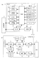
図1は、本発明に係る無線電話システムの構成を示すブロック図である。この無線電話システムは、図1に示すように、充電台1と、この充電台1により充電される携帯電話機である無線電話機2とから構成される。
FIG. 1 is a block diagram showing a configuration of a radiotelephone system according to the present invention. As shown in FIG. 1, the wireless telephone system includes a
充電台1は、図1(a)に示すように、AC100V電源を入力して充電台1の各部に電源電圧Vを供給する電源部11と、電源部11からの電源を無線電話機2に給電して充電させる給電部12と、制御部13と、無線電話機2とデータ伝送を行うための電話機I/F部14と、記憶部15と、表示器であるLCD16A及びLED16Bからなる表示部16と、機能ボタン17A、テンキー(ダイヤルボタン)17B、表示開始ボタン17C、表示消去ボタン17D、データ消去ボタンからなる操作部17と、センサ18と、時計/カレンダ部19とを備えている。
As shown in FIG. 1A, the
また、無線電話機2は、図1(b)に示すように、制御部21と、メモリ22と、表示部23と、操作部24と、無線部25と、アンテナ26と、通話部27と、マイク27と、スピーカ29と、充電台1とデータ伝送を行うための通信I/F部30と、無線電話機2の各部に電源電圧V’を供給する電池31と、充電台1から給電電流を電池31に供給して充電する充電I/F部32とからなる。
In addition, as shown in FIG. 1B, the
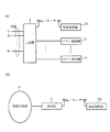
このような無線電話機2として、図2(a)のように、複数の外線を収容するボタン電話装置の主装置4に子機として無線接続が可能な無線電話機2Aと、図2(b)のように、無線基地局5に無線接続が可能な無線電話機2Bとがある。
As such a
ここで、ボタン電話装置の主装置4に無線接続が可能な無線電話機2Aの場合には、操作部24として、ダイヤルボタンの他に、オートダイヤル発信やリダイヤル発信をそれぞれ可能にするオートダイヤルボタンやリダイヤルボタン、主装置4に収容されている外線を選択するための外線ボタンなどの各種機能ボタンが設けられている。そして、オートダイヤルボタンが操作されると、無線電話機2Aの制御部21はメモリ22に登録されているそのオートダイヤルボタンに対応するダイヤル番号(相手電話番号)を読み出して無線部25へ送信し、さらに無線部からアンテナ26を介して主装置4側へ送信させることにより、主装置4から外線を介したオートダイヤルの発信が行われる。また、リダイヤルボタンが操作されると、制御部21はメモリ22のリダイヤル領域に記憶されているリダイヤル番号(電話番号)を読み出して主装置4側へ送信することにより主装置4から外線を介してリダイヤル発信が行われる。さらに、外線ボタンが操作されると、制御部21はこの操作情報を主装置4側へ送信し、主装置4はこの操作情報に応じた外線を捕捉する。
Here, in the case of the radio telephone 2A that can be wirelessly connected to the
また、無線基地局5に無線接続が可能な一般の携帯電話のような無線電話機2Bの場合は、操作部24として、ダイヤルボタンの他に、メモリ22内の電話帳の中から発信相手先を選択するための機能ボタンが設けられている。電話帳には、こうした機能ボタンに対応して、発信相手先名とその電話番号が対に登録され、機能ボタンが操作されると、無線電話機2Bの制御部21は、電話帳から対応する電話番号を読み出し表示部23に表示し、続いてオフフック操作が行われると、読み出した電話番号を無線部25へ送信することにより、無線部25からアンテナ26を介した発信を行わせる。これにより、無線基地局5及び無線交換網6を経由した相手への呼び出しが行われ、相手の応答により通話が可能になる。
In addition, in the case of a
このような無線電話機2は、各機能ボタンに対応した機能情報(機能データ:無線電話機2Aの場合は、後述するオート#1,オート#2,リダイヤル,外線#1,#2といったボタン名(ボタンの名称)、無線電話機2Bの場合は、発信相手先名)がメモリ22に登録され、かつそれぞれの機能ボタンに対応するように表示部23のLCDの各領域に表示される。
Such a
ここで、こうした無線電話機2が充電台1に載置されると、制御部21はメモリ22からこうした機能データを読み出して充電台1へ送信し、充電台1のそれぞれの機能ボタン17Aに対応するようにLCD16Aの各領域に表示させる。また、こうした機能データと一緒にメモリ22に登録されているオートダイヤル番号や、電話帳内の電話番号も読み出して充電台1に送信し、充電台1の記憶部15に格納させる。
Here, when such a
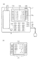
図3は、ボタン電話装置の主装置4に無線接続可能な無線電話機2A側から送信した機能データを充電台1で表示した例を示す図である。充電台1の制御部13は、無線電話機2Aの制御部21がメモリ22から読み出し、通信I/F部30を介して送信された、例えば、無線電話機2Aの各オートダイヤルボタン(各機能ボタン)の名称であるオート#1,オート#2,・・・といった各機能データを、電話機I/F部14を介して受信すると、図3(a)のように、各機能ボタン17Aに対応するLCD16Aの領域に表示する。なお、この受信した各機能データと、同じく受信したこれら各機能データに対応する電話番号(オートダイヤル番号)とを対に記憶部15に格納する。
FIG. 3 is a diagram showing an example in which the function data transmitted from the side of the wireless telephone 2A that can be wirelessly connected to the
また、充電台1の制御部13は、無線電話機2A側から送信された、その無線電話機2Aに設けられた機能ボタンの名称である例えば外線#1,外線#2,リダイヤル,○○(株),○△(株)などの機能データを受信すると、記憶部15に格納するとともに、各機能ボタン17Aに対応するLCD16Aの領域に図3(b)のように表示する。なお、無線電話機2Aは、発信相手先名を表す、○○(株),○△(株)などの機能データを送信する場合、これらの機能データに対応する電話番号もメモリ22から読み出して送信することから、充電台1ではこれらの電話番号を受信して、○○(株),○△(株)などの機能データと対に記憶部15に格納する。
Further, the
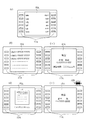
なお、無線基地局5に無線接続が可能な無線電話機2Bから発信相手先名とその電話番号からなる電話帳データが送信された場合は、充電台1では、これらの電話帳データを記憶部15に格納するとともに、受信した発信相手先名(abc,cde,・・・)を、図4(a)のように、各機能ボタン17Aに対応するLCD16Aの領域に表示する。
When telephone book data composed of a destination name and a telephone number is transmitted from the
このような、充電台1において、例えば無線電話機2Bから受信し記憶部15に格納した電話帳データをアクセスするために、図示しないスクロールキーが順次操作されると、充電台1の制御部13は、対応する電話番号を記憶部15から読み出し、LCD16Aの領域に、図4(b)のように、発信相手先名とともにその電話番号を順次表示する。そして、所望の相手に発信するために、該当する機能ボタン17Aが操作されると、制御部13は操作された機能ボタンに応じた電話番号を、電話機I/F部14を介して無線電話機2Bへ送信する。また、このとき、制御部13はLCD16Aに、図4(c)のように、「発信」、「発信相手先名(佐藤和雄)」、「電話番号(03-XXXX-YYZZ)」を表示する。無線電話機2Bの制御部21では、無線電話機2B側から送信された電話番号を通信I/F部30を介して受信し、かつ自身が充電台1から取り上げられてオフフック操作が行われると、受信した電話番号を無線部25へ送信し、無線部25からアンテナ26を介して無線発信を行わせる。これにより、無線基地局5及び無線交換網6を経由した相手への呼び出しが行われ、相手の応答により無線電話機2Bの利用者と相手との通話が行われると、「通話時間」や、「通話料金」などの通話情報が表示される。
In such a
また、充電台1において、例えば無線電話機2Aから受信し記憶部15に格納したオートダイヤル番号をアクセスするために、スクロールキーが順次操作されると、充電台1の制御部13は、対応する各オートダイヤル号を記憶部15から読み出し、LCD16Aの領域に、オート#1,オート#2等のボタン名とともにそのダイヤル番号を順次表示する。そして、所望の相手に発信するために、該当する機能ボタン17Aが操作されると、制御部13は操作された機能ボタンに応じたダイヤル番号を、無線電話機2Aへ送信する。この場合、制御部13はLCD16Aに、図4(c)のように、「発信」、「ボタン名(オート#n)」、「電話番号」を同様に表示する。無線電話機2Bの制御部21では、無線電話機2B側から送信されたダイヤル番号を受信し、かつ自身が充電台1から取り上げられてオフフック操作が行われると、受信したダイヤル番号を無線部25へ送信し、無線部25からアンテナ26を介し主装置4側へ送信させ、主装置4から外線を介した発信を行わせる。これにより、外線を介した相手への呼び出しが行われ、相手の応答により無線電話機2Aの利用者と相手との通話が行われると、「通話時間」や、「通話料金」などの通話情報が表示される。
Further, when the scroll key is sequentially operated in order to access the auto dial number received from, for example, the radio telephone 2A and stored in the
ここで、充電台1に設けられたセンサ18は、その充電台1の周囲に人がいるか否かを検出するものであり、無線電話機2Aまたは無線電話機2Bの通話中に、その通話者が充電台1の周囲にいないことを前記センサ18が検出すると、充電台1の制御部13は、無線電話機2Aまたは無線電話機2Bの通話は終了したと判断して、LCD16Aに表示されている、発信相手先名や、その電話番号、通話時間等の通話詳細情報の表示を消去し、時計/カレンダ部19からのカレンダ、時刻データを読み出して、図4(d)のような、カレンダ/時刻表示を行う。
Here, the
また、無線電話機2が充電台1に載置された状態でこの無線電話機2に着信が到来すると、その着信情報は充電台1側に伝達され、この場合、充電台1はLED16Bを着信表示(点滅表示)するとともに、前記着信情報に含まれる着信相手先が自身の記憶部15に登録されている場合は、その着信相手先の詳細情報を、LCD16Aに、図4(e)のように表示する。
In addition, when an incoming call arrives at the
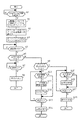
次に、以上のように構成された無線電話システムの要部動作を図5及び図6のフローチャートに基づいて説明する。まず、図5のフローチャートに示される第1の要部動作について説明する。
充電台1に無線電話機2が載置されると、充電台1の給電部12と無線電話機2の充電I/F部32とが接続されて、給電部12から充電I/F部32を介して電池31に電流が供給され、この電流により電池31の充電が行われる。また、このとき、充電台1の電話機I/F部14と無線電話機2の通信I/F部30とが同様に接続され、無線電話機2の制御部21は自身が充電台1に載置されたか否かを、通信I/F部30を介して検出することにより判断する(ステップS1)。
Next, the operation of the main part of the radio telephone system configured as described above will be described with reference to the flowcharts of FIGS. First, the operation of the first main part shown in the flowchart of FIG. 5 will be described.
When the
ここで、無線電話機2が充電台1に載置されたと判定されると(ステップS1のY)、無線電話機2の制御部21はメモリ22に登録されている、前記の機能データ(機能ボタンの名称などの機能データ)及びこれに対応するオートダイヤル番号等、又は発信相手先名及びその電話番号からなる電話帳データを読み出し、充電台1に転送するダウンロードを行う(ステップS2)。充電台1ではこれらのデータを受信すると記憶部15に格納する(ステップS3)。そして、ダウンロードされたデータを、図3(a),(b),図4(a)のようにLCD16Aに表示し、さらに所定操作(例えば図示しないスクロールキー操作)により図4(b)のように表示する。(ステップS4)。
Here, when it is determined that the
ここで、充電台1の或る機能ボタン17Aが操作されることにより対応の電話番号が前述のように無線電話機2側に送られると、充電台1の制御部13はこの無線電話機2の通話が開始されたと判断し(ステップS5のY)、その通話に関する詳細情報として、前述の図4(c)で示される情報をLCD16Aに表示する。なお、無線電話機2側は充電台1から送られる電話番号を受信すると、前述したようにその電話番号を発信し、相手応答により通話状態となる。
Here, when a corresponding telephone number is sent to the
このようにして無線電話機2の通話中にはその通話詳細情報がLCD16Aに表示される。ここで、記憶部15内に、こうした通話詳細情報の表示を継続させる旨の情報が設定されている場合(ステップS6のY)は、充電台1の制御部13は、通話詳細情報の表示を消去せずに継続させ、通話中の無線電話機2の終話を判断する(ステップS7)。ここで、センサ18の出力が充電台1の周囲にその通話者がいないことを示す場合は、制御部13は終話と判断し(ステップS7のY)、LCD16Aに表示されている通話詳細情報を消去し、図4(d)に示すカレンダ/時刻表示を行う(ステップS8)。
In this way, the detailed call information is displayed on the
また、記憶部15内に、通話詳細情報の表示をタイマで消去する旨の情報が設定されている場合(ステップS9のY)は、制御部13は図示しないタイマを起動し、そのタイマの計時による所定期間の経過を判断する(ステップS10)。そして、その所定期間が経過すると、図示しないブザーを一定時間鳴動させて警報音を送出(ステップS11)した後、通話詳細情報を消去し、図4(d)に示すカレンダ/時刻表示を行う(ステップS12)。また、前記所定期間が経過しないうちに無線電話機2の終話が検出されると(ステップS13のY)、同様に通話詳細情報を消去し、図4(d)に示すカレンダ/時刻表示を行う(ステップS14)。
If information indicating that the call detail information display is to be erased by the timer is set in the storage unit 15 (Y in step S9), the
また、記憶部15内に、通話詳細情報の表示を表示消去ボタン17Dの操作により消去する旨の情報が設定されている場合は、その表示消去ボタン17Dの操作の有無を判断する(ステップS15)。ここで、表示消去ボタン17Dの操作が検出された場合は、制御部13は通話詳細情報を消去し、図4(d)に示すカレンダ/時刻表示を行う(ステップS16)。また、表示消去ボタン17Dが操作されずに、無線電話機2の終話が検出されると(ステップS17のY)、同様に通話詳細情報を消去し、図4(d)に示すカレンダ/時刻表示を行う(ステップS18)。
If information indicating that the display of the call detail information is to be deleted by operating the
なお、表示消去ボタン17Dによる消去は常時有効としてもよく、無線電話機2の終話が検出されない場合、或いはタイマの所定期間が経過しない場合であっても表示消去ボタン17Dの操作により消去するようにしても良い。
また、表示開始ボタン17Cを操作することにより、消去されていた通話詳細情報を再表示するようにしても良い。この場合、通話詳細情報に含まれる通話時間は表示が消去されている間も演算を継続しているため、正確な通話時間を再表示できる。
It should be noted that the erasure by the
Further, the deleted call detail information may be displayed again by operating the
また、上記の例では、図4(c)に示す通話詳細情報を消去する場合について説明したが、図3(a),(b),図4(a),(b)に示されるような通話詳細情報以外の表示を消去する場合についても、同様に、記憶部15内の設定情報に基づいて消去される。
このように、無線電話機2に登録されその無線電話機2からダウンロードされて充電台1のLCD16Aに表示されているデータを、必要に応じて消去できるため、例えばその表示データがその無線電話機2を所有する利用者の私用データであったとしてもこの私用データが第三者に知られることを排除でき、これにより、その利用者のプライバシーを保護できる。
Further, in the above example, the case where the detailed call information shown in FIG. 4C is erased has been described, but as shown in FIGS. 3A, 3B, 4A, 4B. Similarly, when the display other than the call detailed information is deleted, the display is similarly deleted based on the setting information in the
In this way, the data registered in the
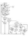
次に、図6のフローチャートに示される第2の要部動作について説明する。
充電台1に無線電話機2が載置されると、無線電話機2の制御部13は自身が充電台1に載置されたか否かを、通信I/F部30を介して検出することにより判断する(ステップS21)。
Next, the second main part operation shown in the flowchart of FIG. 6 will be described.
When the
無線電話機2が充電台1に載置されたと判定されると(ステップS21のY)、無線電話機2の制御部21は、充電台1の記憶部15に設定されている充電台1のID及び設定情報を通信I/F部30を介して入力する。そして、その設定情報が、記憶部15にダウンロードされているデータを消去しない旨の情報であり、かつその充電台1のIDが自身のIDと不一致の場合は充電台1へのデータのダウンロードは行わず、上記条件以外の場合に、メモリ22に登録されている、前記の機能データ(機能ボタンの名称などの機能データ)及びこれに対応するオートダイヤル番号等、又は発信相手先名及びその電話番号からなる電話帳データを読み出し、充電台1に転送するダウンロードを行う(ステップS22)。充電台1の制御部13では、無線電話機2からダウンロードされたデータを受信し、記憶部15に格納する(ステップS23)。この受信データの記憶部15への格納の際には、制御部13は記憶部15に格納されている以前のデータを全て消去してから、その受信データを格納する。これにより、以前のデータがLCD16に表示されることを防止できる。
When it is determined that the
ここで、充電台1の制御部13は、充電台1からその無線電話機2が取り上げられ自身と非接続となったことを電話機I/F部14を介して検出すると(ステップS24のY)、記憶部15内に、その記憶部15のダウンロードデータを直ちに消去する旨の情報が設定されている場合(ステップS25のY)は、記憶部15のダウンロードデータを消去(ステップS26)した後、ステップS21へ戻り、充電台1への再度の無線電話機2の載置の有無を判断する。また、記憶部15内に、その記憶部15のダウンロードデータを消去しない旨の情報が設定されている場合(ステップS27のY)は、記憶部15内のダウンロードデータを消去せずにステップS21に戻る。
Here, when the
また、記憶部15内に、その記憶部15のダウンロードデータをタイマで消去する旨の情報が設定されている場合(ステップS28のY)は、制御部13は図示しないタイマを起動し、そのタイマの計時による所定期間の経過を判断する(ステップS29)。そして、その所定期間が経過すると、記憶部15のダウンロードデータを消去(ステップS30)したうえ、ステップS21に戻る。なお、制御部13は、前記所定期間が経過しないうちに無線電話機2が充電台1に載置されたことを電話機I/F14を介して検出すると(ステップS31のY)、ステップS22へ戻る。この場合、充電台1に載置された無線電話機2は同様に通信I/F部30を介して自身が充電台1に載置されたことを認識し、充電台1に設定されているその充電台1のID及び設定情報を同様に入力して、その設定情報が、記憶部15にダウンロードされているデータを消去しない旨の情報で、かつその充電台1のIDが自身のIDと不一致の場合以外の場合は、自身のメモリ22内の登録データを同様に充電台1へダウンロードする(ステップS22)。
If information indicating that the downloaded data in the
また、記憶部15内に、その記憶部15内のダウンロードデータをデータ消去ボタン17Eの操作により消去する旨の情報が設定されている場合は、制御部13はそのデータ消去ボタン17Eの操作の有無を判断する(ステップS32)。ここで、データ消去ボタン17Eの操作が検出された場合は、制御部13は記憶部15のダウンロードデータを消去(ステップS33)したうえ、ステップS21に戻る。また、制御部13は、データ消去ボタン17Eの操作が検出されずに、無線電話機2が充電台1に載置されたことを電話機I/F14を介して検出すると(ステップS34のY)、ステップS22へ戻る。
If information indicating that the download data in the
このように、無線電話機2に登録されその無線電話機2からダウンロードされて充電台1の記憶部15に格納されたダウンロードデータを、必要に応じて消去できるため、第三者がそのデータを表示させるための操作を行ったとしても充電台1のLCD16には表示できないことから、これらのデータが例えばその無線電話機2を所有する利用者の私用のデータであったとしてもそのデータの第三者への漏洩を阻止することができ、これにより、その利用者のプライバシーを保護できる。
As described above, the downloaded data registered in the
1…充電台、2,2A,2B…無線電話機、31〜3n…ボタン電話機、4…主装置、5…基地局、6…無線交換網、13,21…制御部、14…電話機I/F部、15…記憶部、16,23…表示部、16A…LCD、16B…LED、17,24…操作部、17A…機能ボタン、17B…ダイヤルボタン、17C…表示開始ボタン、17D…表示消去ボタン、17E…データ消去ボタン、18…センサ、22…メモリ、30…通信I/F部。
1 ... charger, 2, 2A, 2B ... radiotelephone, 3 1 to 3 n ... EKT, 4 ... main unit, 5 ... base station, 6 ... wireless switching network, 13, 21 ... controller, 14 ... telephone I / F section, 15 ... storage section, 16, 23 ... display section, 16A ... LCD, 16B ... LED, 17, 24 ... operation section, 17A ... function button, 17B ... dial button, 17C ... display start button, 17D ... display Erase button, 17E ... Data erase button, 18 ... Sensor, 22 ... Memory, 30 ... Communication I / F section.
Claims (8)
前記無線電話機は、機能情報をダウンロードするダウンロード手段を有し、
前記充電台は、少なくとも前記ダウンロード手段のダウンロードに基づく情報を表示する表示手段と、前記情報を消去する消去手段とを有することを特徴とする無線電話システム。 In a wireless telephone system comprising a wireless telephone and a charging base having a connection means for connecting the wireless telephone and capable of charging the wireless telephone,
The wireless telephone has download means for downloading function information,
The wireless telephone system, wherein the charging stand includes display means for displaying at least information based on download by the downloading means, and erasing means for erasing the information.
前記無線電話機は、前記機能データが登録されたメモリを有し、前記充電台は、前記接続手段を介して自身に前記無線電話機が接続されたときに前記ダウンロード手段から前記接続手段を介してダウンロードされる前記メモリの機能データを前記表示手段に表示する表示制御手段を有することを特徴とする無線電話システム。 In claim 1,
The wireless telephone has a memory in which the function data is registered, and the charging stand is downloaded from the downloading means via the connection means when the wireless telephone is connected to the charging base itself. A wireless telephone system comprising display control means for displaying function data of the memory to be displayed on the display means.
前記充電台は、前記接続手段を介して自身に接続された前記無線電話機が通話に移行すると通話情報を前記表示手段に表示する表示制御手段を有することを特徴とする無線電話システム。 In claim 1,
The wireless telephone system, wherein the charging stand includes display control means for displaying call information on the display means when the wireless telephone connected to the charging base shifts to a call.
前記無線電話機は、前記機能データが登録されたメモリを有し、前記充電台は、記憶手段と、前記接続手段を介して自身に前記無線電話機が接続されたときに前記ダウンロード手段から前記接続手段を介してダウンロードされる前記メモリの機能データを前記記憶手段に格納する制御手段とを有することを特徴とする無線電話システム。 In claim 1,
The wireless telephone has a memory in which the function data is registered, and the charging base is connected to the storage means and the connecting means from the downloading means when the wireless telephone is connected to itself via the connecting means. And a control means for storing the function data of the memory downloaded via the storage means in the storage means.
前記充電台はタイマ手段を有し、前記消去手段は、前記表示手段への情報の表示後の前記タイマ手段の計時による所定時間経過後に前記表示手段に表示されている情報を消去することを特徴とする無線電話システム。 In any of claims 1 to 3,
The charging stand has timer means, and the erasing means erases information displayed on the display means after a predetermined time elapses due to time keeping of the timer means after displaying information on the display means. And wireless telephone system.
前記充電台はタイマ手段を有し、前記消去手段は、前記充電台への無線電話機の非接続が検出された後の前記タイマ手段の計時による所定時間経過後に前記記憶手段の格納データを消去することを特徴とする無線電話システム。 In claim 1 or 4,
The charging stand has timer means, and the erasing means erases the stored data in the storage means after a predetermined time elapses due to the timing of the timer means after the disconnection of the radio telephone to the charging stand is detected. A wireless telephone system characterized by that.
前記充電台は、表示開始キーを有し、前記表示開始キーの操作に基づいて前記表示手段への情報の再表示を可能にすることを特徴とする無線電話システム。 In any one of Claims 1, 2, 3, and 5,
The wireless telephone system according to claim 1, wherein the charging stand has a display start key, and information can be displayed again on the display unit based on an operation of the display start key.
自身に接続された前記無線電話機からダウンロードされる機能情報を受信する受信手段と、少なくとも前記受信手段の受信に基づく情報を表示する表示手段と、前記情報を消去する消去手段とを有することを特徴とする充電台。
In a charging stand having a connection means with a wireless telephone, and capable of charging the wireless telephone,
It comprises a receiving means for receiving function information downloaded from the radio telephone connected to itself, a display means for displaying information based on reception of at least the receiving means, and an erasing means for erasing the information. And charging stand.
Priority Applications (1)
| Application Number | Priority Date | Filing Date | Title |
|---|---|---|---|
| JP2004103411A JP4311256B2 (en) | 2004-03-31 | 2004-03-31 | Wireless telephone system and charging stand |
Applications Claiming Priority (1)
| Application Number | Priority Date | Filing Date | Title |
|---|---|---|---|
| JP2004103411A JP4311256B2 (en) | 2004-03-31 | 2004-03-31 | Wireless telephone system and charging stand |
Publications (2)
| Publication Number | Publication Date |
|---|---|
| JP2005294953A true JP2005294953A (en) | 2005-10-20 |
| JP4311256B2 JP4311256B2 (en) | 2009-08-12 |
Family
ID=35327444
Family Applications (1)
| Application Number | Title | Priority Date | Filing Date |
|---|---|---|---|
| JP2004103411A Expired - Fee Related JP4311256B2 (en) | 2004-03-31 | 2004-03-31 | Wireless telephone system and charging stand |
Country Status (1)
| Country | Link |
|---|---|
| JP (1) | JP4311256B2 (en) |
Cited By (1)
| Publication number | Priority date | Publication date | Assignee | Title |
|---|---|---|---|---|
| JP2016110654A (en) * | 2014-12-08 | 2016-06-20 | 日本圧着端子製造株式会社 | Charger for portable apparatus, and portable apparatus |
-
2004
- 2004-03-31 JP JP2004103411A patent/JP4311256B2/en not_active Expired - Fee Related
Cited By (1)
| Publication number | Priority date | Publication date | Assignee | Title |
|---|---|---|---|---|
| JP2016110654A (en) * | 2014-12-08 | 2016-06-20 | 日本圧着端子製造株式会社 | Charger for portable apparatus, and portable apparatus |
Also Published As
| Publication number | Publication date |
|---|---|
| JP4311256B2 (en) | 2009-08-12 |
Similar Documents
| Publication | Publication Date | Title |
|---|---|---|
| RU2437242C1 (en) | Loudspeaker device for use in vehicle | |
| JP6766859B2 (en) | In-vehicle hands-free device and data transfer method | |
| JP2003022066A (en) | Communication terminal device and method for displaying space character | |
| JP5063261B2 (en) | Communication device | |
| JP2002335567A (en) | Portable telephone auxiliary equipment | |
| JP2008245044A (en) | Data backup device for portable terminal | |
| JP4311256B2 (en) | Wireless telephone system and charging stand | |
| KR100663480B1 (en) | How do I delete a message on my mobile device? | |
| JP2006319892A (en) | Mobile radio terminal device | |
| JP3590546B2 (en) | Cordless telephone | |
| JP2013176000A (en) | Mobile terminal and control method therefor | |
| JP4244843B2 (en) | Wireless terminal system and charging stand | |
| JP4294075B2 (en) | Mobile phone | |
| JP4703475B2 (en) | Portable information equipment | |
| JP3886444B2 (en) | Telephone | |
| JP5023354B2 (en) | Mobile radio terminal device | |
| JP4322229B2 (en) | Telephone equipment | |
| KR100626215B1 (en) | How to schedule and send a message from a mobile terminal | |
| KR100621750B1 (en) | Wireless communication terminal having call list storage function and method thereof | |
| JP2011049747A (en) | Cordless telephone system | |
| KR100630201B1 (en) | How to Select and Transfer Data from a Portable Terminal | |
| JP2003324515A (en) | Data transfer method between terminals | |
| JP3702875B2 (en) | Communication device | |
| JP4001074B2 (en) | Telephone system | |
| JP2009033496A (en) | Portable communication terminal and program |
Legal Events
| Date | Code | Title | Description |
|---|---|---|---|
| A621 | Written request for application examination |
Free format text: JAPANESE INTERMEDIATE CODE: A621 Effective date: 20061030 |
|
| A977 | Report on retrieval |
Free format text: JAPANESE INTERMEDIATE CODE: A971007 Effective date: 20081016 |
|
| A131 | Notification of reasons for refusal |
Free format text: JAPANESE INTERMEDIATE CODE: A131 Effective date: 20081028 |
|
| A521 | Request for written amendment filed |
Free format text: JAPANESE INTERMEDIATE CODE: A523 Effective date: 20081212 |
|
| A131 | Notification of reasons for refusal |
Free format text: JAPANESE INTERMEDIATE CODE: A131 Effective date: 20090120 |
|
| A521 | Request for written amendment filed |
Free format text: JAPANESE INTERMEDIATE CODE: A523 Effective date: 20090312 |
|
| TRDD | Decision of grant or rejection written | ||
| A01 | Written decision to grant a patent or to grant a registration (utility model) |
Free format text: JAPANESE INTERMEDIATE CODE: A01 Effective date: 20090421 |
|
| A01 | Written decision to grant a patent or to grant a registration (utility model) |
Free format text: JAPANESE INTERMEDIATE CODE: A01 |
|
| A61 | First payment of annual fees (during grant procedure) |
Free format text: JAPANESE INTERMEDIATE CODE: A61 Effective date: 20090504 |
|
| FPAY | Renewal fee payment (event date is renewal date of database) |
Free format text: PAYMENT UNTIL: 20120522 Year of fee payment: 3 |
|
| R150 | Certificate of patent or registration of utility model |
Ref document number: 4311256 Country of ref document: JP Free format text: JAPANESE INTERMEDIATE CODE: R150 Free format text: JAPANESE INTERMEDIATE CODE: R150 |
|
| FPAY | Renewal fee payment (event date is renewal date of database) |
Free format text: PAYMENT UNTIL: 20120522 Year of fee payment: 3 |
|
| FPAY | Renewal fee payment (event date is renewal date of database) |
Free format text: PAYMENT UNTIL: 20130522 Year of fee payment: 4 |
|
| FPAY | Renewal fee payment (event date is renewal date of database) |
Free format text: PAYMENT UNTIL: 20130522 Year of fee payment: 4 |
|
| LAPS | Cancellation because of no payment of annual fees |