JP2016108398A - Element - Google Patents
Element Download PDFInfo
- Publication number
- JP2016108398A JP2016108398A JP2014245346A JP2014245346A JP2016108398A JP 2016108398 A JP2016108398 A JP 2016108398A JP 2014245346 A JP2014245346 A JP 2014245346A JP 2014245346 A JP2014245346 A JP 2014245346A JP 2016108398 A JP2016108398 A JP 2016108398A
- Authority
- JP
- Japan
- Prior art keywords
- metal
- carbon fiber
- composite member
- heat
- fiber
- Prior art date
- Legal status (The legal status is an assumption and is not a legal conclusion. Google has not performed a legal analysis and makes no representation as to the accuracy of the status listed.)
- Granted
Links
Images
Classifications
-
- F—MECHANICAL ENGINEERING; LIGHTING; HEATING; WEAPONS; BLASTING
- F28—HEAT EXCHANGE IN GENERAL
- F28F—DETAILS OF HEAT-EXCHANGE AND HEAT-TRANSFER APPARATUS, OF GENERAL APPLICATION
- F28F21/00—Constructions of heat-exchange apparatus characterised by the selection of particular materials
- F28F21/06—Constructions of heat-exchange apparatus characterised by the selection of particular materials of plastics material
- F28F21/067—Details
-
- B—PERFORMING OPERATIONS; TRANSPORTING
- B32—LAYERED PRODUCTS
- B32B—LAYERED PRODUCTS, i.e. PRODUCTS BUILT-UP OF STRATA OF FLAT OR NON-FLAT, e.g. CELLULAR OR HONEYCOMB, FORM
- B32B5/00—Layered products characterised by the non- homogeneity or physical structure, i.e. comprising a fibrous, filamentary, particulate or foam layer; Layered products characterised by having a layer differing constitutionally or physically in different parts
- B32B5/02—Layered products characterised by the non- homogeneity or physical structure, i.e. comprising a fibrous, filamentary, particulate or foam layer; Layered products characterised by having a layer differing constitutionally or physically in different parts characterised by structural features of a fibrous or filamentary layer
- B32B5/12—Layered products characterised by the non- homogeneity or physical structure, i.e. comprising a fibrous, filamentary, particulate or foam layer; Layered products characterised by having a layer differing constitutionally or physically in different parts characterised by structural features of a fibrous or filamentary layer characterised by the relative arrangement of fibres or filaments of different layers, e.g. the fibres or filaments being parallel or perpendicular to each other
-
- B—PERFORMING OPERATIONS; TRANSPORTING
- B32—LAYERED PRODUCTS
- B32B—LAYERED PRODUCTS, i.e. PRODUCTS BUILT-UP OF STRATA OF FLAT OR NON-FLAT, e.g. CELLULAR OR HONEYCOMB, FORM
- B32B5/00—Layered products characterised by the non- homogeneity or physical structure, i.e. comprising a fibrous, filamentary, particulate or foam layer; Layered products characterised by having a layer differing constitutionally or physically in different parts
- B32B5/22—Layered products characterised by the non- homogeneity or physical structure, i.e. comprising a fibrous, filamentary, particulate or foam layer; Layered products characterised by having a layer differing constitutionally or physically in different parts characterised by the presence of two or more layers which are next to each other and are fibrous, filamentary, formed of particles or foamed
- B32B5/24—Layered products characterised by the non- homogeneity or physical structure, i.e. comprising a fibrous, filamentary, particulate or foam layer; Layered products characterised by having a layer differing constitutionally or physically in different parts characterised by the presence of two or more layers which are next to each other and are fibrous, filamentary, formed of particles or foamed one layer being a fibrous or filamentary layer
- B32B5/26—Layered products characterised by the non- homogeneity or physical structure, i.e. comprising a fibrous, filamentary, particulate or foam layer; Layered products characterised by having a layer differing constitutionally or physically in different parts characterised by the presence of two or more layers which are next to each other and are fibrous, filamentary, formed of particles or foamed one layer being a fibrous or filamentary layer another layer next to it also being fibrous or filamentary
-
- B—PERFORMING OPERATIONS; TRANSPORTING
- B64—AIRCRAFT; AVIATION; COSMONAUTICS
- B64C—AEROPLANES; HELICOPTERS
- B64C1/00—Fuselages; Constructional features common to fuselages, wings, stabilising surfaces or the like
-
- C—CHEMISTRY; METALLURGY
- C08—ORGANIC MACROMOLECULAR COMPOUNDS; THEIR PREPARATION OR CHEMICAL WORKING-UP; COMPOSITIONS BASED THEREON
- C08J—WORKING-UP; GENERAL PROCESSES OF COMPOUNDING; AFTER-TREATMENT NOT COVERED BY SUBCLASSES C08B, C08C, C08F, C08G or C08H
- C08J5/00—Manufacture of articles or shaped materials containing macromolecular substances
- C08J5/04—Reinforcing macromolecular compounds with loose or coherent fibrous material
- C08J5/0405—Reinforcing macromolecular compounds with loose or coherent fibrous material with inorganic fibres
- C08J5/042—Reinforcing macromolecular compounds with loose or coherent fibrous material with inorganic fibres with carbon fibres
-
- C—CHEMISTRY; METALLURGY
- C08—ORGANIC MACROMOLECULAR COMPOUNDS; THEIR PREPARATION OR CHEMICAL WORKING-UP; COMPOSITIONS BASED THEREON
- C08J—WORKING-UP; GENERAL PROCESSES OF COMPOUNDING; AFTER-TREATMENT NOT COVERED BY SUBCLASSES C08B, C08C, C08F, C08G or C08H
- C08J5/00—Manufacture of articles or shaped materials containing macromolecular substances
- C08J5/04—Reinforcing macromolecular compounds with loose or coherent fibrous material
- C08J5/047—Reinforcing macromolecular compounds with loose or coherent fibrous material with mixed fibrous material
-
- C—CHEMISTRY; METALLURGY
- C08—ORGANIC MACROMOLECULAR COMPOUNDS; THEIR PREPARATION OR CHEMICAL WORKING-UP; COMPOSITIONS BASED THEREON
- C08J—WORKING-UP; GENERAL PROCESSES OF COMPOUNDING; AFTER-TREATMENT NOT COVERED BY SUBCLASSES C08B, C08C, C08F, C08G or C08H
- C08J5/00—Manufacture of articles or shaped materials containing macromolecular substances
- C08J5/04—Reinforcing macromolecular compounds with loose or coherent fibrous material
- C08J5/06—Reinforcing macromolecular compounds with loose or coherent fibrous material using pretreated fibrous materials
-
- C—CHEMISTRY; METALLURGY
- C09—DYES; PAINTS; POLISHES; NATURAL RESINS; ADHESIVES; COMPOSITIONS NOT OTHERWISE PROVIDED FOR; APPLICATIONS OF MATERIALS NOT OTHERWISE PROVIDED FOR
- C09K—MATERIALS FOR MISCELLANEOUS APPLICATIONS, NOT PROVIDED FOR ELSEWHERE
- C09K5/00—Heat-transfer, heat-exchange or heat-storage materials, e.g. refrigerants; Materials for the production of heat or cold by chemical reactions other than by combustion
- C09K5/08—Materials not undergoing a change of physical state when used
- C09K5/14—Solid materials, e.g. powdery or granular
-
- B—PERFORMING OPERATIONS; TRANSPORTING
- B32—LAYERED PRODUCTS
- B32B—LAYERED PRODUCTS, i.e. PRODUCTS BUILT-UP OF STRATA OF FLAT OR NON-FLAT, e.g. CELLULAR OR HONEYCOMB, FORM
- B32B2262/00—Composition or structural features of fibres which form a fibrous or filamentary layer or are present as additives
- B32B2262/10—Inorganic fibres
- B32B2262/106—Carbon fibres, e.g. graphite fibres
-
- B—PERFORMING OPERATIONS; TRANSPORTING
- B32—LAYERED PRODUCTS
- B32B—LAYERED PRODUCTS, i.e. PRODUCTS BUILT-UP OF STRATA OF FLAT OR NON-FLAT, e.g. CELLULAR OR HONEYCOMB, FORM
- B32B2605/00—Vehicles
- B32B2605/18—Aircraft
-
- B—PERFORMING OPERATIONS; TRANSPORTING
- B64—AIRCRAFT; AVIATION; COSMONAUTICS
- B64C—AEROPLANES; HELICOPTERS
- B64C1/00—Fuselages; Constructional features common to fuselages, wings, stabilising surfaces or the like
- B64C1/40—Sound or heat insulation, e.g. using insulation blankets
-
- B—PERFORMING OPERATIONS; TRANSPORTING
- B64—AIRCRAFT; AVIATION; COSMONAUTICS
- B64C—AEROPLANES; HELICOPTERS
- B64C1/00—Fuselages; Constructional features common to fuselages, wings, stabilising surfaces or the like
- B64C2001/0054—Fuselage structures substantially made from particular materials
- B64C2001/0072—Fuselage structures substantially made from particular materials from composite materials
-
- C—CHEMISTRY; METALLURGY
- C08—ORGANIC MACROMOLECULAR COMPOUNDS; THEIR PREPARATION OR CHEMICAL WORKING-UP; COMPOSITIONS BASED THEREON
- C08J—WORKING-UP; GENERAL PROCESSES OF COMPOUNDING; AFTER-TREATMENT NOT COVERED BY SUBCLASSES C08B, C08C, C08F, C08G or C08H
- C08J2363/00—Characterised by the use of epoxy resins; Derivatives of epoxy resins
-
- F—MECHANICAL ENGINEERING; LIGHTING; HEATING; WEAPONS; BLASTING
- F28—HEAT EXCHANGE IN GENERAL
- F28F—DETAILS OF HEAT-EXCHANGE AND HEAT-TRANSFER APPARATUS, OF GENERAL APPLICATION
- F28F13/00—Arrangements for modifying heat-transfer, e.g. increasing, decreasing
- F28F2013/001—Particular heat conductive materials, e.g. superconductive elements
-
- F—MECHANICAL ENGINEERING; LIGHTING; HEATING; WEAPONS; BLASTING
- F28—HEAT EXCHANGE IN GENERAL
- F28F—DETAILS OF HEAT-EXCHANGE AND HEAT-TRANSFER APPARATUS, OF GENERAL APPLICATION
- F28F2255/00—Heat exchanger elements made of materials having special features or resulting from particular manufacturing processes
- F28F2255/06—Heat exchanger elements made of materials having special features or resulting from particular manufacturing processes composite, e.g. polymers with fillers or fibres
-
- Y—GENERAL TAGGING OF NEW TECHNOLOGICAL DEVELOPMENTS; GENERAL TAGGING OF CROSS-SECTIONAL TECHNOLOGIES SPANNING OVER SEVERAL SECTIONS OF THE IPC; TECHNICAL SUBJECTS COVERED BY FORMER USPC CROSS-REFERENCE ART COLLECTIONS [XRACs] AND DIGESTS
- Y02—TECHNOLOGIES OR APPLICATIONS FOR MITIGATION OR ADAPTATION AGAINST CLIMATE CHANGE
- Y02T—CLIMATE CHANGE MITIGATION TECHNOLOGIES RELATED TO TRANSPORTATION
- Y02T50/00—Aeronautics or air transport
- Y02T50/40—Weight reduction
Landscapes
- Chemical & Material Sciences (AREA)
- Engineering & Computer Science (AREA)
- Materials Engineering (AREA)
- Organic Chemistry (AREA)
- Chemical Kinetics & Catalysis (AREA)
- Medicinal Chemistry (AREA)
- Polymers & Plastics (AREA)
- Manufacturing & Machinery (AREA)
- Health & Medical Sciences (AREA)
- Physics & Mathematics (AREA)
- Mechanical Engineering (AREA)
- Thermal Sciences (AREA)
- Aviation & Aerospace Engineering (AREA)
- Inorganic Chemistry (AREA)
- Combustion & Propulsion (AREA)
- General Engineering & Computer Science (AREA)
- Laminated Bodies (AREA)
- Moulding By Coating Moulds (AREA)
- Reinforced Plastic Materials (AREA)
Abstract
【課題】航空機の発熱部で発生した熱を効率良く放出できる部材を提供する。【解決手段】部材は、金属コート炭素繊維及びピッチ系炭素繊維の一方又は両方を含む熱伝導性炭素繊維で強化されたプラスチックを有する第1複合部材を備え、繊維方向に関して熱伝導性炭素繊維の一端部が発熱部に配置され、熱伝導性炭素繊維の他端部が放熱部に配置される。【選択図】図2A member capable of efficiently releasing heat generated in a heat generating part of an aircraft is provided. The member includes a first composite member having a plastic reinforced with thermally conductive carbon fibers including one or both of metal-coated carbon fibers and pitch-based carbon fibers, the thermally conductive carbon fibers being in the fiber direction. One end portion is disposed in the heat generating portion, and the other end portion of the heat conductive carbon fiber is disposed in the heat radiating portion. [Selection] Figure 2
Description
本発明は、航空機又は人工衛星などに使用される部材に関する。 The present invention relates to a member used for an aircraft or an artificial satellite.
航空機は、電子機器、バッテリ、及びエンジンのような発熱部を有する。発熱部で発生した熱は、熱流路材と呼ばれる部材を介して放出(排熱)される。従来、航空機の熱流路材として、金属シート又はジャンパー線が用いられている。人工衛星において使用される紙製のハニカムコアを有する熱流制御体の一例が特許文献1に開示されている。 The aircraft has heat generating parts such as an electronic device, a battery, and an engine. The heat generated in the heat generating part is released (exhaust heat) through a member called a heat channel material. Conventionally, a metal sheet or a jumper wire has been used as a heat flow path material for an aircraft. An example of a heat flow control body having a paper honeycomb core used in an artificial satellite is disclosed in Patent Document 1.
近年において、航空機の部材の材料は、金属から複合材に遷移している。また、航空機の高度化に伴い、電子機器の使用が増大している。すなわち、近年においては、発熱部の発熱量が増大しているのに対し、航空機の部材の熱伝導率は低下している。そのため、発熱部で発生した熱を効率良く放出できる技術の案出が要望される。 In recent years, the material of aircraft components has transitioned from metals to composites. In addition, with the advancement of aircraft, the use of electronic devices is increasing. That is, in recent years, while the amount of heat generated by the heat generating portion has increased, the thermal conductivity of aircraft members has decreased. Therefore, it is desired to devise a technique that can efficiently release the heat generated in the heat generating portion.
本発明の態様は、航空機又は人工衛星などの発熱部で発生した熱を効率良く放出できる部材を提供することを目的とする。 An object of an aspect of the present invention is to provide a member that can efficiently release heat generated in a heat generating part such as an aircraft or an artificial satellite.
本発明の第1の態様に従えば、金属コート炭素繊維及びピッチ系炭素繊維の一方又は両方を含む熱伝導性炭素繊維で強化されたプラスチックを有する第1複合部材を備え、繊維方向に関して前記熱伝導性炭素繊維の一端部が発熱部に配置され、前記熱伝導性炭素繊維の他端部が放熱部に配置される部材が提供される。 According to a first aspect of the present invention, there is provided a first composite member having a plastic reinforced with thermally conductive carbon fibers including one or both of metal-coated carbon fibers and pitch-based carbon fibers, and the heat A member is provided in which one end portion of the conductive carbon fiber is disposed in the heat generating portion and the other end portion of the thermally conductive carbon fiber is disposed in the heat radiating portion.
本発明の第1の態様によれば、第1複合部材が金属コート炭素繊維及びピッチ系炭素繊維の一方又は両方を含む熱伝導性炭素繊維で強化された炭素繊維強化プラスチックを含み、その熱伝導性炭素繊維の一端部が発熱部に配置され、他端部が放熱部に配置される。そのため、発熱部で発生した熱は、熱伝導性炭素繊維を伝わって、効率良く放熱部に放出される。また、第1複合部材は、航空機又は人工衛星などの強度部材として使用可能である。そのため、金属シート又はジャンパー線のような専用の熱流路材を別途設けなくても、発熱部の熱を放熱部に放出することができる。そのため、重量の増大を抑制しつつ、発熱部で発生した熱が、効率良く放熱部に放出される。また、熱伝導性炭素繊維とプラスチックとは一緒に成型されるので、ロバスト性が向上する。 According to the first aspect of the present invention, the first composite member includes a carbon fiber reinforced plastic reinforced with a thermally conductive carbon fiber including one or both of a metal-coated carbon fiber and a pitch-based carbon fiber. One end portion of the carbon fiber is disposed in the heat generating portion, and the other end portion is disposed in the heat radiating portion. Therefore, the heat generated in the heat generating part is transmitted to the heat conductive carbon fiber and efficiently released to the heat radiating part. The first composite member can be used as a strength member for an aircraft or an artificial satellite. Therefore, the heat of the heat generating portion can be released to the heat radiating portion without separately providing a dedicated heat channel material such as a metal sheet or a jumper wire. Therefore, the heat generated in the heat generating part is efficiently released to the heat radiating part while suppressing an increase in weight. In addition, since the thermally conductive carbon fiber and the plastic are molded together, the robustness is improved.
本発明の第2の態様に従えば、金属コート炭素繊維及びピッチ系炭素繊維の一方又は両方を含む熱伝導性炭素繊維で強化されたプラスチックを有する第1複合部材を備え、繊維方向に関して前記熱伝導性炭素繊維の中央部が発熱部に配置され、前記熱伝導性炭素繊維の一端部及び他端部が放熱部に配置される部材が提供される。 According to a second aspect of the present invention, the method comprises a first composite member having a plastic reinforced with thermally conductive carbon fibers including one or both of metal-coated carbon fibers and pitch-based carbon fibers, wherein the heat There is provided a member in which a central portion of the conductive carbon fiber is disposed in the heat generating portion, and one end portion and the other end portion of the thermally conductive carbon fiber are disposed in the heat radiating portion.
本発明の第2の態様によれば、熱伝導性炭素繊維の中央部が発熱部に配置され、一端部及び他端部が放熱部に配置されるので、発熱部で発生した熱は、熱伝導性炭素繊維を伝わって、効率良く放熱部に放出される。そのため、重量の増大を抑制しつつ、発熱部で発生した熱が、効率良く放熱部に放出される。また、熱伝導性炭素繊維とプラスチックとは一緒に成型されるので、ロバスト性が向上する。 According to the second aspect of the present invention, since the central portion of the thermally conductive carbon fiber is disposed in the heat generating portion and the one end portion and the other end portion are disposed in the heat radiating portion, the heat generated in the heat generating portion is the heat It is efficiently discharged to the heat dissipation part through the conductive carbon fiber. Therefore, the heat generated in the heat generating part is efficiently released to the heat radiating part while suppressing an increase in weight. In addition, since the thermally conductive carbon fiber and the plastic are molded together, the robustness is improved.
本発明の第1の態様又は第2の態様において、前記第1複合部材は、前記繊維方向と交差する並列方向に配置された複数の前記熱伝導性炭素繊維を含むプリプレグシートを前記繊維方向及び前記並列方向と交差する積層方向に複数積層した積層体を含み、前記繊維方向に関する熱伝導率は、前記並列方向に関する熱伝導率及び前記積層方向に関する熱伝導率よりも大きくてもよい。 In the first aspect or the second aspect of the present invention, the first composite member includes a prepreg sheet including a plurality of the heat conductive carbon fibers arranged in a parallel direction intersecting the fiber direction. A plurality of stacked bodies may be stacked in a stacking direction that intersects the parallel direction, and the thermal conductivity related to the fiber direction may be larger than the thermal conductivity related to the parallel direction and the thermal conductivity related to the stacking direction.
これにより、熱伝導率に異方性が付与されるので、発熱部で発生した熱が、並列方向及び積層方向に伝わることが抑制され、放熱部に効率良く放出される。 Thereby, since anisotropy is imparted to the thermal conductivity, the heat generated in the heat generating portion is suppressed from being transmitted in the parallel direction and the stacking direction, and is efficiently released to the heat radiating portion.
本発明の第1の態様及び第2の態様において、前記第1複合部材は板状部材であり、前記第1複合部材の表面及び裏面の一方又は両方に配置され、炭素繊維で強化されたプラスチックを含む第2複合部材を備え、前記熱伝導性炭素繊維の一端部及び他端部のそれぞれは露出してもよい。 In the first and second aspects of the present invention, the first composite member is a plate-like member, and is disposed on one or both of the front surface and the back surface of the first composite member and reinforced with carbon fiber. The one end part and the other end part of the heat conductive carbon fiber may be exposed.
これにより、第1複合部材が第2複合部材で支持され、強度が維持される。熱伝導性炭素繊維の一端部及び他端部のそれぞれは、第2複合部材で覆われずに露出するので、発熱部で発生した熱は、放熱部から効率良く放出される。 Thereby, the first composite member is supported by the second composite member, and the strength is maintained. Since each of the one end part and the other end part of the heat conductive carbon fiber is exposed without being covered with the second composite member, the heat generated in the heat generating part is efficiently released from the heat radiating part.
本発明の第1の態様及び第2の態様において、前記発熱部は、前記航空機の電子機器を含み、前記放熱部は、前記航空機の燃料タンクを含んでもよい。 In the first and second aspects of the present invention, the heat generating unit may include electronic equipment of the aircraft, and the heat radiating unit may include a fuel tank of the aircraft.
これにより、電子機器の発熱量が増大しても、電子機器で発生した熱は、燃料タンクに効率良く放出される。 Thereby, even if the calorific value of the electronic device increases, the heat generated in the electronic device is efficiently released to the fuel tank.
本発明の態様によれば、発熱部で発生した熱を効率良く放出できる部材が提供される。 According to the aspect of the present invention, a member capable of efficiently releasing the heat generated in the heat generating portion is provided.
以下、本発明に係る実施形態について図面を参照しながら説明するが、本発明はこれに限定されない。以下で説明する各実施形態の構成要素は、適宜組み合わせることができる。また、一部の構成要素を用いない場合もある。 Hereinafter, embodiments according to the present invention will be described with reference to the drawings, but the present invention is not limited thereto. The components of each embodiment described below can be combined as appropriate. Some components may not be used.
<第1実施形態>
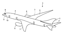
第1実施形態について説明する。図1は、本実施形態に係る航空機1の一例を示す図である。図1に示すように、航空機1は、胴体2と、主翼3と、水平尾翼4と、垂直尾翼5と、エンジン6と、燃料タンク7と、コックピット8と、電子機器9と、バッテリ10と、を備えている。
<First Embodiment>
A first embodiment will be described. FIG. 1 is a diagram illustrating an example of an aircraft 1 according to the present embodiment. As shown in FIG. 1, the aircraft 1 includes a
胴体2、主翼3、水平尾翼4、及び垂直尾翼5の少なくとも一部は、複合材で形成されている。複合材は、炭素繊維で強化されたプラスチックである炭素繊維強化プラスチック(carbon fiber reinforced plastic:CFRP)を含む。なお、複合材が、ガラス繊維で強化されたプラスチックであるガラス繊維強化プラスチック(glass fiber reinforced plastic:GFRP)を含んでもよい。
At least a part of the
なお、胴体2、主翼3、水平尾翼4、及び垂直尾翼5の少なくとも一部が、アルミニウム合金(ジュラルミン)のような金属で形成されてもよい。
Note that at least a part of the
本実施形態において、航空機1の部材の少なくとも一部は、金属コート炭素繊維(MC)で強化されたプラスチックである金属コート炭素繊維強化プラスチックを有する。金属コート炭素繊維で強化されたプラスチックは、MC−CFRP、とも呼ばれる。金属コート炭素繊維は、熱伝導性を有する熱伝導性炭素繊維である。 In this embodiment, at least a part of the members of the aircraft 1 has a metal-coated carbon fiber reinforced plastic that is a plastic reinforced with metal-coated carbon fibers (MC). Plastics reinforced with metal-coated carbon fibers are also called MC-CFRP. The metal-coated carbon fiber is a thermally conductive carbon fiber having thermal conductivity.
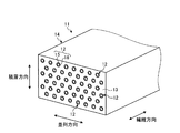
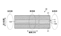
図2は、本実施形態に係る金属コート炭素繊維強化プラスチックを含む複合部材11の一例を模式的に示す斜視図である。図2に示すように、複合部材11は、金属コート炭素繊維12で強化されたプラスチック13である金属コート炭素繊維強化プラスチック14を有する。金属コート炭素繊維12は、炭素繊維15と、炭素繊維15に被覆された金属16とを有する。
FIG. 2 is a perspective view schematically showing an example of the
複合部材11は、複数の金属コート炭素繊維12を有する。金属コート炭素繊維12は、第1の方向に長い。複数の金属コート炭素繊維12が、第1の方向と直交する第2の方向に並列に並べられる。また、複数の金属コート炭素繊維12が、第1の方向及び第2の方向と直交する第3の方向に配置される。
The
以下の説明においては、金属コート炭素繊維12の長手方向(第1の方向)を適宜、繊維方向、と称する。また、以下の説明においては、複数の金属コート炭素繊維12が並べられる方向(第2の方向)を適宜、並列方向、と称する。また、以下の説明においては、複数の金属コート炭素繊維12が配置される方向(第3の方向)を適宜、積層方向、と称する。
In the following description, the longitudinal direction (first direction) of the metal-coated
複数の金属コート炭素繊維12は、並列方向及び積層方向のそれぞれに関して、間隔をあけて配置される。複数の金属コート炭素繊維12の間に、プラスチック13が配置される。本実施形態において、プラスチック13は、エポキシ樹脂を含む。
The plurality of metal-coated
金属コート炭素繊維12の炭素繊維15の直径は、例えば、5μm以上10μm以下である。炭素繊維15の表面に金属16が被覆されている。金属16の熱伝導率は、炭素繊維15の熱伝導率よりも高い。プラスチック13の熱伝導率は、金属16の熱伝導率及び炭素繊維15の熱伝導率よりも低い。すなわち、プラスチック13の熱伝導率は、金属コート炭素繊維12の熱伝導率よりも低い。
The diameter of the
本実施形態において、金属16は、ニッケルである。金属コート炭素繊維12は、ニッケルコート炭素繊維である。なお、金属16は、金、銀、及び銅の少なくとも一つでもよい。
In the present embodiment, the
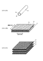
図3は、本実施形態に係る複合部材11の製造方法の一例を模式的に示す図である。図3の(ステップA)に示すように、金属コート炭素繊維12が製造される。金属コート炭素繊維12は、直径が5μmから10μm程度の炭素繊維15に金属16を被覆することによって製造される。本実施形態においては、金属16として、ニッケルが被覆される。なお、金属16として、金、銀、及び銅の少なくとも一つが被覆されてもよい。
FIG. 3 is a diagram schematically illustrating an example of a method for manufacturing the
図3の(ステップB)に示すように、複数の金属コート炭素繊維12が並列方向に並べられ、エポキシ樹脂のようなブラスチック13で固められる。複数の金属コート炭素繊維12は、撚らずに、引き揃えられた状態で、プラスチック13で固められる。
As shown in FIG. 3 (step B), a plurality of metal-coated
並列方向は、繊維方向に配置された複数の金属コート炭素繊維12が並べられる方向である。繊維方向と並列方向とは直交する。
The parallel direction is a direction in which a plurality of metal-coated
プラスチック13と、並列方向に配置されプラスチック13で固められた複数の金属コート炭素繊維12とを含むシート状の部材は、プリプレグシート17、と呼ばれる。
A sheet-like member including the plastic 13 and the plurality of metal-coated
図3の(ステップC)に示すように、製造された複数のプリプレグシート17が積層方向に積層される。
As shown in (Step C) of FIG. 3, a plurality of manufactured
積層方向は、プリプレグシート17が複数積層される方向である。積層方向は、繊維方向及び並列方向と直交する。
The stacking direction is a direction in which a plurality of
プリプレグシート17の積層体は、オートクレーブと呼ばれる加熱加圧装置で、高温高圧下で加熱処理される。これにより、複数のプリプレグシート17の積層体である複合部材11が製造される。
The laminated body of the
なお、本実施形態においては、複数のプリプレグシート17の金属コート炭素繊維12が全て同一方向に配置される、所謂、一方向積層であることとした。第1のプリプレグシート17の金属コート繊維12が第1の方向に配置され、第1のプリプレグシート17に重なる第2のプリプレグシート17の金属コート繊維12が第1のプリプレグシート17の第1の方向と交差する第2の方向に配置される、所謂、クロスプライ積層でもよい。
In the present embodiment, the metal-coated
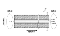
図4は、本実施形態に係る航空機1用の部材(熱流路材)20の一例を示す断面図である。本実施形態において、部材20は、複合部材11と、複合部材11に接続される複合部材21と、を含む。部材20は、胴体2、主翼3、水平尾翼4、及び垂直尾翼5の少なくとも一部に使用される。
FIG. 4 is a cross-sectional view illustrating an example of a member (heat channel material) 20 for the aircraft 1 according to the present embodiment. In the present embodiment, the
例えば、金属コート炭素繊維12を含むプリプレグシートと、金属が被覆されていない炭素繊維を含むプリブレクシートとが積層され、その積層体がオートクレーブで加熱加圧処理されることによって、部材20が製造されてもよい。
For example, a
図4に示すように、繊維方向に関して金属コート炭素繊維12の一端部12Aが航空機1の発熱部に配置される。繊維方向に関して金属コート炭素繊維12の他端部12Bが航空機1の放熱部に配置される。
As shown in FIG. 4, one
航空機1の発熱部は、例えば、航空機1の電子機器9、バッテリ10、及びエンジン6の少なくとも一つを含む。また、発熱部は、電子機器9の筐体を含む。航空機1の放熱部は、例えば、航空機1の燃料タンク7を含む。なお、航空機1の放熱部が、航空機1の外部空間(胴体2の外面に面する空間)でもよい。
The heating unit of the aircraft 1 includes, for example, at least one of the electronic device 9, the
複合部材11は、板状部材である。図4に示す例では、複合部材11の表面及び裏面のそれぞれに、複合部材21が配置される。複合部材21は、炭素繊維で強化されたプラスチックを含む炭素繊維強化プラスチックを有する。
The
複合部材21の炭素繊維強化プラスチックの炭素繊維には、金属が被覆されていない。繊維方向に関する複合部材21の熱伝導率は、繊維方向に関する複合部材11の熱伝導率よりも低い。並列方向に関する複合部材21の熱伝導率は、繊維方向に関する複合部材11の熱伝導率よりも低い。積層方向に関する複合部材21の熱伝導率は、繊維方向に関する複合部材11の熱伝導率よりも低い。
The carbon fiber of the carbon fiber reinforced plastic of the
なお、並列方向に関する複合部材21の熱伝導率は、並列方向に関する複合部材11の熱伝導率と等しくてもよいし、並列方向に関する複合部材11よりも低くてもよい。積層方向に関する複合部材21の熱伝導率は、積層方向に関する複合部材11の熱伝導率と等しくてもよいし、積層方向に関する複合部材11よりも低くてもよい。
Note that the thermal conductivity of the
金属コート炭素繊維12の一端部12A及び他端部12Bのそれぞれに、複合部材21は配置されない。金属コート炭素繊維12の一端部12A及び他端部12Bのそれぞれは、露出する。金属コート炭素繊維12の一端部12Aは、発熱部と接触する。なお、金属コート炭素繊維12の一端部12Aは、発熱部と間隙を介して対向してもよい。金属コート炭素繊維12の他端部12Bは、放熱部と接触する。金属コート炭素繊維12の他端部12Bは、放熱部と間隙を介して対向してもよい。
The
なお、複合部材21は、複合部材11の表面に配置され、複合部材11の裏面に配置されなくてもよい。複合部材21は、複合部材11の裏面に配置され、複合部材11の表面に配置されなくてもよい。複合部材21は、複合部材11の表面及び裏面の両方に配置されなくてもよい。
Note that the
部材20の繊維方向に金属コート炭素繊維12が配置されている。部材20の並列方向及び積層方向のそれぞれにおいて、複数の金属コート炭素繊維12の間にプラスチック13が配置されている。繊維方向に関する部材20の熱伝導率は、並列方向に関する部材20の熱伝導率及び積層方向に関する部材20の熱伝導率よりも大きい。
Metal-coated
発熱部の熱は、一端部12Aより金属コート炭素繊維12に吸収される。金属コート炭素繊維12に吸収された熱は、その金属コート炭素繊維12を伝わって、他端部12Bより放出(排熱)される。
The heat of the heat generating part is absorbed by the metal-coated
並列方向に関する部材20の熱伝導率及び積層方向に関する部材20の熱伝導率は、繊維方向に関する部材20の熱伝導率よりも小さい。したがって、金属コート炭素繊維12の熱は、専ら、繊維方向に移動する。金属コート炭素繊維12の熱が並列方向及び積層方向に伝達することは抑制される。
The thermal conductivity of the
また、本実施形態においては、積層方向に関して複合部材11の表面及び裏面のそれぞれに複合部材21が配置される。繊維方向、並列方向、及び積層方向のそれぞれの複合部材21の熱伝達率は、繊維方向に関する複合部材11の熱伝達率よりも小さい。そのため、金属コート炭素繊維12の熱が、複合部材21の表面から放出されることが抑制される。
Moreover, in this embodiment, the
以上説明したように、本実施形態によれば、複合部材11が金属コート炭素繊維12で強化された金属コート炭素繊維強化プラスチック14を含み、その金属コート炭素繊維12の一端部12Aが航空機1の発熱部に配置され、金属コート炭素繊維12の他端部12Bが航空機1の放熱部に配置される。金属コート炭素繊維12の金属16は、高い熱伝導率を有する。そのため、発熱部で発生した熱は、金属コート炭素繊維12を伝わって、効率良く放熱部に放出される。
As described above, according to the present embodiment, the
また、複合部材11は、航空機1の強度部材として使用可能である。そのため、従来のような、金属シート又はジャンパー線のような専用の熱流路材を別途設けなくても、発熱部の熱を放熱部に放出できる。そのため、航空機1の重量の増大を抑制しつつ、航空機1の発熱部で発生した熱は、効率良く放熱部に放出される。
The
本実施形態においては、複合部材11は、繊維方向と交差する並列方向に配置された複数の金属コート炭素繊維12を含むプリプレグシート17を、繊維方向及び並列方向と交差する積層方向に複数積層した積層体を含む。繊維方向に関する部材20の熱伝導率は、並列方向に関する部材20の熱伝導率及び積層方向に関する部材の熱伝導率よりも大きい。これにより、熱伝導率に異方性が付与され、発熱部で発生した熱が、並列方向及び積層方向に伝わることが抑制され、放熱部に効率良く放出される。例えば、部材20の並列方向及び積層方向の少なくとも一方に、加熱したくない部材又は機器が存在する場合、熱伝達率に異方性を持つ部材20によって、その部材又は機器に熱が伝達されることが抑制される。
In the present embodiment, the
本実施形態においては、複合部材11は板状部材であり、部材20は、複合部材11の表面及び裏面の一方又は両方に配置された炭素繊維強化プラスチックを含む複合部材21を備える。これにより、複合部材11が複合部材21で支持され、強度が維持される。また、複合部材21の熱伝導率は、繊維方向に関する複合部材11の熱伝導率よりも小さい。そのため、部材20の並列方向及び積層方向の少なくとも一方に、加熱したくない部材又は機器が存在する場合、複合部材21によって、その部材又は機器に熱が伝達されることが抑制される。
In the present embodiment, the
また、本実施形態においては、金属コート炭素繊維12の一端部12A及び他端部12Bのそれぞれは、複合部材21などによって覆われてなく、露出する。一端部12Aが露出しているので、発熱部で発生した熱は、一端部12Aを介して、金属コート炭素繊維12の金属16に効率良く吸収される。他端部12Bが露出しているので、発熱部で発生し、金属コート炭素繊維12の金属16を移動した熱は、他端部12Bを介して、放熱部に効率良く放出される。このように、本実施形態においては、金属コート炭素繊維12の一端部12A及び他端部12Bのそれぞれは露出しているので、発熱部で発生した熱は、放熱部から効率良く放出される。
In the present embodiment, each of the one
本実施形態においては、航空機1の発熱部は、航空機1の電子機器9を含む。航空機1の放熱部は、航空機1の燃料タンク7を含む。これにより、航空機1の高度化により、電子機器9の使用が増大し、電子機器9の発熱量が増大しても、電子機器9で発生した熱は、燃料タンク7に効率良く放出される。
In the present embodiment, the heat generating part of the aircraft 1 includes the electronic device 9 of the aircraft 1. The heat radiating unit of the aircraft 1 includes the
<第2実施形態>
第2実施形態について説明する。以下の説明において、上述の実施形態と同一又は同等の構成部分については同一の符号を付し、その説明を簡略又は省略する。
Second Embodiment
A second embodiment will be described. In the following description, the same or equivalent components as those in the above-described embodiment are denoted by the same reference numerals, and the description thereof is simplified or omitted.
図5は、部材20の使用方法の一例を示す断面図である。図5に示すように、航空機1の発熱部が、部材20のうち、一端部12Aと他端部12Bとの間の中央部に配置されてもよい。すなわち、繊維方向に関して金属コート炭素繊維12の中央部が発熱部に配置され、金属コート炭素繊維12の一端部12A及び他端部12Bが放熱部に配置されてもよい。本実施形態においては、一端部12A及び他端部12Bのそれぞれが、航空機1の放熱部に配置される。発熱部で発生した熱は、一端部12A及び他端部12Bのそれぞれから放出される。また、金属コート炭素繊維12の一端部12A及び他端部12Bのそれぞれが露出することにより、発熱部で発生した熱は、放熱部から効率良く放出される。
FIG. 5 is a cross-sectional view showing an example of how to use the
<第3実施形態>
第3実施形態について説明する。以下の説明において、上述の実施形態と同一又は同等の構成部分については同一の符号を付し、その説明を簡略又は省略する。
<Third Embodiment>
A third embodiment will be described. In the following description, the same or equivalent components as those in the above-described embodiment are denoted by the same reference numerals, and the description thereof is simplified or omitted.
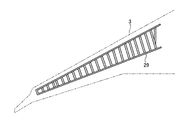
図6は、航空機1の主翼3の平面図を示す。リブライン29の少なくとも一部に、後述するシアタイ(構造材)31が配置される。
FIG. 6 shows a plan view of the main wing 3 of the aircraft 1. A shear tie (structural material) 31 to be described later is disposed on at least a part of the
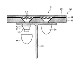
図7は、外板30とシアタイ31との位置関係を概略的に示す図である。シアタイ31は、ストリンガ、リブ等と外板30とを結合する部材である。本実施形態において、シアタイ31は、炭素繊維強化プラスチックを含む複合部材21と、金属コート炭素繊維強化プラスチック14を含む複合部材11とによって形成される。
FIG. 7 is a diagram schematically showing the positional relationship between the
外板30とシアタイ31とは、ファスナ51によって固定される。ファスナ51の先端にカラー(ナット)37が結合されることによって、外板30とシアタイ31とが固定される。カラー37とシアタイ31との間には、ワッシャ41及びスペーサ42が配置される。
The
カラー37、ワッシャ41、及びスペーサ42は、キャップ44によって覆われる。キャップ44は、シアタイ31に密着するように配置される。
The
外板30は、炭素繊維強化プラスチック層32と、ガラス繊維強化プラスチック層34と、銅ペイント層39と、を含む。
The
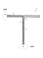
図8は、本実施形態に係るシアタイ31の一例を示す断面図である。シアタイ31は、炭素繊維強化プラスチックを含む複合部材21と、金属コート炭素繊維強化プラスチック14を含む複合部材11とによって形成される。複合部材11は、複合部材21によって挟まれる。複合部材11は、シアタイ31の一部に設けられる。図8において、シアタイ31の下端部に、複合部材11の金属コート炭素繊維12の一端部12Aが配置される。シアタイ31の左側の上端部に、複合部材11の金属コート炭素繊維12の他端部12Bが配置される。図8に示す例では、シアタイ31の右側の上端部は、複合部材21によって形成される。
FIG. 8 is a sectional view showing an example of the
シアタイ31の下端部に、航空機1の発熱部が配置される。シアタイ31の左側の上端部に、航空機1の放熱部が配置される。
The heat generating portion of the aircraft 1 is disposed at the lower end portion of the
なお、シアタイ31の右側の上端部に、複合部材11の金属コート炭素繊維12の他端部12Bが配置され、航空機1の放熱部が配置されてもよい。なお、シアタイ31の右側の上端部及び左側の上端部の両方に、複合部材11の金属コート炭素繊維12の他端部12Bが配置され、航空機1の放熱部が配置されてもよい。なお、シアタイ31の右側の上端部及び左側の上端部の一方又は両方に、複合部材11の金属コート炭素繊維12の一端部12Aが配置され、航空機1の発熱部が配置されてもよい。シアタイ31の下端部に、複合部材11の金属コート炭素繊維12の他端部12Bが配置され、航空機1の放熱部が配置されてもよい。
Note that the
以上説明したように、複合部材11及び複合部材21が曲げられていてもよいし、任意の形状(3次元形状)に加工されてもよい。
As described above, the
なお、上述の各実施形態において、金属コート炭素繊維12に代えて、又は金属コート炭素繊維12とともに、ピッチ系炭素繊維が配置されてもよい。ピッチ系炭素繊維は、少なくともPAN炭素繊維よりも高い熱伝導率を有する熱伝導性炭素繊維である。
In each of the above-described embodiments, pitch-based carbon fibers may be arranged in place of the metal-coated
なお、上述の各実施形態においては、部材20が航空機1の構造部材に使用される例について説明した。部材20は、人工衛星の構造部材に使用されてもよい。
In each of the above-described embodiments, the example in which the
なお、上述の各実施形態においては、繊維方向と並列方向と積層方向とは、互いに直交することとした。繊維方向と並列方向とが、例えば80度以上100度以下の角度で交差してもよい。繊維方向と積層方向とが、例えば80度以上100度以下の角度で交差してもよい。並列方向と積層方向とが、例えば80度以上100度以下の角度で交差してもよい。 In each of the above-described embodiments, the fiber direction, the parallel direction, and the stacking direction are orthogonal to each other. The fiber direction and the parallel direction may intersect at an angle of, for example, 80 degrees or more and 100 degrees or less. The fiber direction and the lamination direction may intersect at an angle of, for example, 80 degrees or more and 100 degrees or less. For example, the parallel direction and the stacking direction may intersect at an angle of not less than 80 degrees and not more than 100 degrees.
1 航空機
2 胴体
3 主翼
4 水平尾翼
5 垂直尾翼
6 エンジン
7 燃料タンク
8 コックピット
9 電子機器
10 バッテリ
11 複合部材
12 金属コート炭素繊維
12A 一端部
12B 他端部
13 プラスチック
14 金属コート炭素繊維強化プラスチック
15 炭素繊維
16 金属
17 プリプレグシート
20 部材
21 複合部材
29 リブライン
30 外板
31 シアタイ
32 炭素繊維強化プラスチック層
34 ガラス繊維強化プラスチック層
37 カラー
39 銅ペイント層
41 ワッシャ
42 スペーサ
44 キャップ
51 ファスナ
DESCRIPTION OF SYMBOLS 1
Claims (5)
繊維方向に関して前記熱伝導性炭素繊維の一端部が発熱部に配置され、前記熱伝導性炭素繊維の他端部が放熱部に配置される部材。 A first composite member comprising a plastic reinforced with thermally conductive carbon fibers including one or both of metal-coated carbon fibers and pitch-based carbon fibers;
A member in which one end portion of the thermally conductive carbon fiber is disposed in the heat generating portion and the other end portion of the thermally conductive carbon fiber is disposed in the heat radiating portion with respect to the fiber direction.
繊維方向に関して前記熱伝導性炭素繊維の中央部が発熱部に配置され、前記熱伝導性炭素繊維の一端部及び他端部が放熱部に配置される部材。 A first composite member comprising a plastic reinforced with thermally conductive carbon fibers including one or both of metal-coated carbon fibers and pitch-based carbon fibers;
A member in which a central portion of the thermally conductive carbon fiber is disposed in the heat generating portion with respect to the fiber direction, and one end portion and the other end portion of the thermally conductive carbon fiber are disposed in the heat radiating portion.
前記繊維方向に関する熱伝導率は、前記並列方向に関する熱伝導率及び前記積層方向に関する熱伝導率よりも大きい請求項1又は請求項2に記載の部材。 The first composite member is a laminate in which a plurality of prepreg sheets including a plurality of the heat conductive carbon fibers arranged in a parallel direction intersecting the fiber direction are laminated in the fiber direction and a lamination direction intersecting the parallel direction. Including
The member according to claim 1 or 2, wherein the thermal conductivity in the fiber direction is larger than the thermal conductivity in the parallel direction and the thermal conductivity in the stacking direction.
前記第1複合部材の表面及び裏面の一方又は両方に配置され、炭素繊維で強化されたプラスチックを含む第2複合部材を備え、
前記熱伝導性炭素繊維の一端部及び他端部のそれぞれは露出する請求項1から請求項3のいずれか一項に記載の部材。 The first composite member is a plate member,
A second composite member comprising a plastic reinforced with carbon fiber disposed on one or both of the front and back surfaces of the first composite member;
The member according to any one of claims 1 to 3, wherein each of one end and the other end of the thermally conductive carbon fiber is exposed.
Priority Applications (4)
| Application Number | Priority Date | Filing Date | Title |
|---|---|---|---|
| JP2014245346A JP6550230B2 (en) | 2014-12-03 | 2014-12-03 | Element |
| PCT/JP2015/080002 WO2016088470A1 (en) | 2014-12-03 | 2015-10-23 | Member |
| EP15864708.1A EP3214112B1 (en) | 2014-12-03 | 2015-10-23 | Heat passage member |
| US15/531,606 US20180281983A1 (en) | 2014-12-03 | 2015-10-23 | Member |
Applications Claiming Priority (1)
| Application Number | Priority Date | Filing Date | Title |
|---|---|---|---|
| JP2014245346A JP6550230B2 (en) | 2014-12-03 | 2014-12-03 | Element |
Publications (3)
| Publication Number | Publication Date |
|---|---|
| JP2016108398A true JP2016108398A (en) | 2016-06-20 |
| JP2016108398A5 JP2016108398A5 (en) | 2017-11-30 |
| JP6550230B2 JP6550230B2 (en) | 2019-07-24 |
Family
ID=56091426
Family Applications (1)
| Application Number | Title | Priority Date | Filing Date |
|---|---|---|---|
| JP2014245346A Active JP6550230B2 (en) | 2014-12-03 | 2014-12-03 | Element |
Country Status (4)
| Country | Link |
|---|---|
| US (1) | US20180281983A1 (en) |
| EP (1) | EP3214112B1 (en) |
| JP (1) | JP6550230B2 (en) |
| WO (1) | WO2016088470A1 (en) |
Cited By (3)
| Publication number | Priority date | Publication date | Assignee | Title |
|---|---|---|---|---|
| JP2020062768A (en) * | 2018-10-15 | 2020-04-23 | 有限会社ヒロセ金型 | Method for producing carbon fiber reinforced resin molded product and carbon fiber reinforced resin molded product |
| JP2021017647A (en) * | 2019-07-18 | 2021-02-15 | ハミルトン・サンドストランド・コーポレイションHamilton Sundstrand Corporation | Method of forming component, method of plate and frame heat exchanger, and heat exchange plate |
| WO2021201165A1 (en) * | 2020-04-03 | 2021-10-07 | 日本製鉄株式会社 | Power storage device structure and heat dissipation method for power storage device |
Families Citing this family (3)
| Publication number | Priority date | Publication date | Assignee | Title |
|---|---|---|---|---|
| US10723437B2 (en) * | 2017-05-30 | 2020-07-28 | The Boeing Company | System for structurally integrated thermal management for thin wing aircraft control surface actuators |
| WO2020092217A1 (en) | 2018-11-01 | 2020-05-07 | Atomos Nuclear and Space Corporation | Carbon fiber radiator fin system |
| CN114474557B (en) * | 2021-12-31 | 2023-11-10 | 富联裕展科技(深圳)有限公司 | Metal plastic bonding part, forming method thereof and electronic product shell |
Citations (10)
| Publication number | Priority date | Publication date | Assignee | Title |
|---|---|---|---|---|
| JP2001073255A (en) * | 1999-08-31 | 2001-03-21 | Fujikura Rubber Ltd | Heat-releasing sheet |
| US20030116678A1 (en) * | 2001-12-21 | 2003-06-26 | Gardner Slade H. | Aircraft structures having improved through-thickness thermal conductivity |
| JP2004528717A (en) * | 2001-04-30 | 2004-09-16 | サーモ コムポジット、エルエルシー | Thermal management materials, devices and methods |
| JP2005213459A (en) * | 2004-01-30 | 2005-08-11 | Nippon Steel Corp | High thermal conductivity material |
| JP2006513390A (en) * | 2002-12-19 | 2006-04-20 | スリーエム イノベイティブ プロパティズ カンパニー | Flexible heat absorber |
| WO2006112487A1 (en) * | 2005-04-18 | 2006-10-26 | Teijin Limited | Pitch-derived carbon fibers, mat, and molded resin containing these |
| JP2008138968A (en) * | 2006-12-04 | 2008-06-19 | Honda Motor Co Ltd | Manufacturing method of heat exchanger and heat exchanger |
| JP2010229238A (en) * | 2009-03-26 | 2010-10-14 | Mitsubishi Plastics Inc | Carbon fiber reinforced resin sheet and roll wound body thereof |
| JP2011046967A (en) * | 2010-12-07 | 2011-03-10 | Mitsubishi Engineering Plastics Corp | Thermoconductive polycarbonate resin composition and molding |
| JP2011100959A (en) * | 2009-10-05 | 2011-05-19 | Sumitomo Electric Ind Ltd | Flexible board, flexible board module, and method for manufacturing both |
Family Cites Families (1)
| Publication number | Priority date | Publication date | Assignee | Title |
|---|---|---|---|---|
| JP5352893B2 (en) * | 2008-04-14 | 2013-11-27 | 東洋炭素株式会社 | Carbon fiber carbon composite molded body, carbon fiber reinforced carbon composite material, and method for producing the same |
-
2014
- 2014-12-03 JP JP2014245346A patent/JP6550230B2/en active Active
-
2015
- 2015-10-23 US US15/531,606 patent/US20180281983A1/en not_active Abandoned
- 2015-10-23 EP EP15864708.1A patent/EP3214112B1/en active Active
- 2015-10-23 WO PCT/JP2015/080002 patent/WO2016088470A1/en not_active Ceased
Patent Citations (10)
| Publication number | Priority date | Publication date | Assignee | Title |
|---|---|---|---|---|
| JP2001073255A (en) * | 1999-08-31 | 2001-03-21 | Fujikura Rubber Ltd | Heat-releasing sheet |
| JP2004528717A (en) * | 2001-04-30 | 2004-09-16 | サーモ コムポジット、エルエルシー | Thermal management materials, devices and methods |
| US20030116678A1 (en) * | 2001-12-21 | 2003-06-26 | Gardner Slade H. | Aircraft structures having improved through-thickness thermal conductivity |
| JP2006513390A (en) * | 2002-12-19 | 2006-04-20 | スリーエム イノベイティブ プロパティズ カンパニー | Flexible heat absorber |
| JP2005213459A (en) * | 2004-01-30 | 2005-08-11 | Nippon Steel Corp | High thermal conductivity material |
| WO2006112487A1 (en) * | 2005-04-18 | 2006-10-26 | Teijin Limited | Pitch-derived carbon fibers, mat, and molded resin containing these |
| JP2008138968A (en) * | 2006-12-04 | 2008-06-19 | Honda Motor Co Ltd | Manufacturing method of heat exchanger and heat exchanger |
| JP2010229238A (en) * | 2009-03-26 | 2010-10-14 | Mitsubishi Plastics Inc | Carbon fiber reinforced resin sheet and roll wound body thereof |
| JP2011100959A (en) * | 2009-10-05 | 2011-05-19 | Sumitomo Electric Ind Ltd | Flexible board, flexible board module, and method for manufacturing both |
| JP2011046967A (en) * | 2010-12-07 | 2011-03-10 | Mitsubishi Engineering Plastics Corp | Thermoconductive polycarbonate resin composition and molding |
Cited By (7)
| Publication number | Priority date | Publication date | Assignee | Title |
|---|---|---|---|---|
| JP2020062768A (en) * | 2018-10-15 | 2020-04-23 | 有限会社ヒロセ金型 | Method for producing carbon fiber reinforced resin molded product and carbon fiber reinforced resin molded product |
| JP7149577B2 (en) | 2018-10-15 | 2022-10-07 | 有限会社ヒロセ金型 | Method for manufacturing carbon fiber reinforced resin molded product, and carbon fiber reinforced resin molded product |
| JP2021017647A (en) * | 2019-07-18 | 2021-02-15 | ハミルトン・サンドストランド・コーポレイションHamilton Sundstrand Corporation | Method of forming component, method of plate and frame heat exchanger, and heat exchange plate |
| JP7319904B2 (en) | 2019-07-18 | 2023-08-02 | ハミルトン・サンドストランド・コーポレイション | Methods of forming components, methods of forming plate and frame heat exchangers and heat exchange plates |
| WO2021201165A1 (en) * | 2020-04-03 | 2021-10-07 | 日本製鉄株式会社 | Power storage device structure and heat dissipation method for power storage device |
| JPWO2021201165A1 (en) * | 2020-04-03 | 2021-10-07 | ||
| JP7430248B2 (en) | 2020-04-03 | 2024-02-09 | 日本製鉄株式会社 | Energy storage device structure and heat dissipation method for energy storage device structure |
Also Published As
| Publication number | Publication date |
|---|---|
| JP6550230B2 (en) | 2019-07-24 |
| WO2016088470A1 (en) | 2016-06-09 |
| EP3214112A1 (en) | 2017-09-06 |
| EP3214112A4 (en) | 2017-11-22 |
| US20180281983A1 (en) | 2018-10-04 |
| EP3214112B1 (en) | 2021-04-14 |
Similar Documents
| Publication | Publication Date | Title |
|---|---|---|
| JP6550230B2 (en) | Element | |
| CN103338929B (en) | Comprise the multifunctional composite of Viscoelastic Sandwich | |
| US10425989B2 (en) | Heated floor panels with thermally conductive and electrically insulating fabric | |
| US11338933B2 (en) | Acoustic honeycomb panel with integrated electrical heater | |
| US9776386B2 (en) | Manufacturing method of partially cured composite components | |
| CN109346448B (en) | A kind of graphene composite cold plate and preparation method thereof | |
| WO2015119064A1 (en) | Thermally conductive composite material, and manufacturing method therefor | |
| JP6238168B2 (en) | Composite structure | |
| US9974209B1 (en) | Heat sink and method | |
| EP3407678A1 (en) | Method of making complex carbon nanotube sheets | |
| JP2016108398A5 (en) | ||
| EP3339178B1 (en) | Electrically conductive resin matrix for cnt heater | |
| CN206602672U (en) | Electric heating structure for preventing and removing ice of airplane | |
| JP2013028166A (en) | Method of manufacturing thermal protection composite material | |
| CN110654526A (en) | Temperature equalizing method and structure for high-temperature and high-heat part | |
| US6612523B2 (en) | Aircraft structures having improved through-thickness thermal conductivity | |
| CN110021567A (en) | Cooler | |
| CN206758647U (en) | A kind of dorsal fin structure | |
| CN202944564U (en) | Connecting structure for pelvic fin and control cabin | |
| EP3135475B1 (en) | Composite material structure | |
| CN109177368A (en) | A kind of graphite film lamination composite board and preparation method thereof | |
| JP2010023240A (en) | Manufacturing method of heat-defensive composite material | |
| JP6547982B2 (en) | Chopped tape fiber reinforced thermoplastic resin sheet material and method for manufacturing the same | |
| CN205631564U (en) | Lamination board structure | |
| US20140110158A1 (en) | Carbon fiber spacecraft panel with integral metallic foil power return |
Legal Events
| Date | Code | Title | Description |
|---|---|---|---|
| A521 | Request for written amendment filed |
Free format text: JAPANESE INTERMEDIATE CODE: A523 Effective date: 20171016 |
|
| A621 | Written request for application examination |
Free format text: JAPANESE INTERMEDIATE CODE: A621 Effective date: 20171016 |
|
| A131 | Notification of reasons for refusal |
Free format text: JAPANESE INTERMEDIATE CODE: A131 Effective date: 20181204 |
|
| A521 | Request for written amendment filed |
Free format text: JAPANESE INTERMEDIATE CODE: A523 Effective date: 20190115 |
|
| TRDD | Decision of grant or rejection written | ||
| A01 | Written decision to grant a patent or to grant a registration (utility model) |
Free format text: JAPANESE INTERMEDIATE CODE: A01 Effective date: 20190604 |
|
| A61 | First payment of annual fees (during grant procedure) |
Free format text: JAPANESE INTERMEDIATE CODE: A61 Effective date: 20190701 |
|
| R150 | Certificate of patent or registration of utility model |
Ref document number: 6550230 Country of ref document: JP Free format text: JAPANESE INTERMEDIATE CODE: R150 |