JP2016051663A - Electric wire with terminal and method of manufacturing electric wire with terminal - Google Patents
Electric wire with terminal and method of manufacturing electric wire with terminal Download PDFInfo
- Publication number
- JP2016051663A JP2016051663A JP2014177600A JP2014177600A JP2016051663A JP 2016051663 A JP2016051663 A JP 2016051663A JP 2014177600 A JP2014177600 A JP 2014177600A JP 2014177600 A JP2014177600 A JP 2014177600A JP 2016051663 A JP2016051663 A JP 2016051663A
- Authority
- JP
- Japan
- Prior art keywords
- electric wire
- terminal
- crimping
- connection
- core wire
- Prior art date
- Legal status (The legal status is an assumption and is not a legal conclusion. Google has not performed a legal analysis and makes no representation as to the accuracy of the status listed.)
- Pending
Links
- 238000004519 manufacturing process Methods 0.000 title claims description 18
- 238000002788 crimping Methods 0.000 claims abstract description 83
- 239000011248 coating agent Substances 0.000 claims abstract description 13
- 238000000576 coating method Methods 0.000 claims abstract description 13
- 238000005304 joining Methods 0.000 claims description 12
- 238000003825 pressing Methods 0.000 claims description 6
- 230000015572 biosynthetic process Effects 0.000 abstract 1
- 238000007789 sealing Methods 0.000 description 38
- 238000003466 welding Methods 0.000 description 18
- 238000000034 method Methods 0.000 description 15
- 229910052751 metal Inorganic materials 0.000 description 11
- 239000002184 metal Substances 0.000 description 11
- RYGMFSIKBFXOCR-UHFFFAOYSA-N Copper Chemical compound [Cu] RYGMFSIKBFXOCR-UHFFFAOYSA-N 0.000 description 5
- 229910052802 copper Inorganic materials 0.000 description 5
- 239000010949 copper Substances 0.000 description 5
- 150000002739 metals Chemical class 0.000 description 5
- 239000000463 material Substances 0.000 description 4
- 229910000881 Cu alloy Inorganic materials 0.000 description 3
- 229910052782 aluminium Inorganic materials 0.000 description 3
- XAGFODPZIPBFFR-UHFFFAOYSA-N aluminium Chemical compound [Al] XAGFODPZIPBFFR-UHFFFAOYSA-N 0.000 description 3
- 239000004020 conductor Substances 0.000 description 3
- 230000008878 coupling Effects 0.000 description 3
- 238000010168 coupling process Methods 0.000 description 3
- 238000005859 coupling reaction Methods 0.000 description 3
- 230000004048 modification Effects 0.000 description 3
- 238000012986 modification Methods 0.000 description 3
- 239000011347 resin Substances 0.000 description 3
- 229920005989 resin Polymers 0.000 description 3
- 230000004308 accommodation Effects 0.000 description 2
- 230000007797 corrosion Effects 0.000 description 2
- 238000005260 corrosion Methods 0.000 description 2
- 239000007788 liquid Substances 0.000 description 2
- 239000007769 metal material Substances 0.000 description 2
- 230000002093 peripheral effect Effects 0.000 description 2
- 238000007747 plating Methods 0.000 description 2
- 238000005476 soldering Methods 0.000 description 2
- 229910000838 Al alloy Inorganic materials 0.000 description 1
- 229910001369 Brass Inorganic materials 0.000 description 1
- 229910001128 Sn alloy Inorganic materials 0.000 description 1
- ATJFFYVFTNAWJD-UHFFFAOYSA-N Tin Chemical compound [Sn] ATJFFYVFTNAWJD-UHFFFAOYSA-N 0.000 description 1
- 239000000853 adhesive Substances 0.000 description 1
- 230000001070 adhesive effect Effects 0.000 description 1
- 238000005452 bending Methods 0.000 description 1
- 239000010951 brass Substances 0.000 description 1
- 239000003795 chemical substances by application Substances 0.000 description 1
- 238000005520 cutting process Methods 0.000 description 1
- 230000000694 effects Effects 0.000 description 1
- 239000008151 electrolyte solution Substances 0.000 description 1
- 238000007765 extrusion coating Methods 0.000 description 1
- 239000011810 insulating material Substances 0.000 description 1
- 238000009413 insulation Methods 0.000 description 1
- 150000003839 salts Chemical class 0.000 description 1
- XLYOFNOQVPJJNP-UHFFFAOYSA-N water Substances O XLYOFNOQVPJJNP-UHFFFAOYSA-N 0.000 description 1
Images
Landscapes
- Manufacturing Of Electrical Connectors (AREA)
- Connections Effected By Soldering, Adhesion, Or Permanent Deformation (AREA)
Abstract
【課題】本発明は、端子の端部に露出する芯線を収容可能な圧着部を容易に形成できるようにすることを目的とする。【解決手段】芯線14と、芯線14を覆う被覆18とを含み、端部で芯線が露出している電線12と、接続部22と、接続部22に接合された圧着部30とを含む端子20とを備える。圧着部30は一端部が閉じられた筒形状に形成されており、露出芯線部14aが圧着部30内に収容された状態で、圧着部30の他端部が被覆18の端部を覆うと共に圧着部30が露出した芯線14に圧着されて、電線12の端部に取付けられている。【選択図】図1An object of the present invention is to facilitate formation of a crimping portion capable of accommodating a core wire exposed at the end of a terminal. A terminal includes an electric wire (12) including a core wire (14), a coating (18) covering the core wire (14), the core wire being exposed at an end, a connecting portion (22), and a crimping portion (30) joined to the connecting portion (22). 20. The crimping portion 30 is formed in a cylindrical shape with one end closed, and the other end of the crimping portion 30 covers the end of the coating 18 while the exposed core wire portion 14a is accommodated in the crimping portion 30. The crimping portion 30 is crimped onto the exposed core wire 14 and attached to the end of the electric wire 12 . [Selection drawing] Fig. 1
Description
この発明は、電線の端部に端子が取付けられた端子付電線に関する。 The present invention relates to a terminal-attached electric wire in which a terminal is attached to an end portion of the electric wire.
特許文献1は、筒状の圧着部内に、剥き出しになった被覆電線の導体から絶縁被覆の先端部までを挿入する技術を開示している。また、圧着部のうち端子接続部側の端部に、圧潰された形状で止水性を有する封止部を形成し、この封止部に、その長手方向と直交する方向に延びる溶接部を形成してより止水性を高めることが開示されている。 Patent document 1 is disclosing the technique which inserts from the conductor of the covered covered electric wire to the front-end | tip part of insulation coating in the cylindrical crimping | compression-bonding part. In addition, a sealed portion having a water-tightness is formed in a crushed shape at the end of the crimped portion on the terminal connection portion side, and a welded portion extending in a direction orthogonal to the longitudinal direction is formed on the sealed portion. Thus, it has been disclosed to increase the water-stopping property.
特許文献1では、板状基材を、プレス加工によって丸めて筒状に形成し、その筒状部の端縁同士を溶接し、これにより、筒状の圧着部を形成している。しかしながら、筒状部の端縁同士の溶接は、精度良く行う必要がある。 In patent document 1, a plate-shaped base material is rounded by press work to form a cylindrical shape, and the edges of the cylindrical portion are welded to each other, thereby forming a cylindrical crimping portion. However, it is necessary to accurately weld the edges of the cylindrical portion.
そこで、本発明は、端子の端部に露出する芯線を収容可能な圧着部を容易に形成できるようにすることを目的とする。 Then, an object of this invention is to enable it to form easily the crimping | compression-bonding part which can accommodate the core wire exposed to the edge part of a terminal.
上記課題を解決するため、第1の態様に係る端子付電線は、芯線と、前記芯線を覆う被覆とを含み、端部で前記芯線が露出している電線と、接続部と、前記接続部に接合された圧着部とを含み、前記圧着部は一端部が閉じられた筒形状に形成されており、露出した前記芯線が前記圧着部内に収容された状態で、前記圧着部の他端部が前記被覆の端部を覆うと共に前記圧着部が露出した前記芯線に圧着されて、前記電線の端部に取付けられた端子と、を備える。 In order to solve the above problem, a terminal-attached electric wire according to a first aspect includes a core wire and a coating covering the core wire, the electric wire with the core wire exposed at an end, a connection portion, and the connection portion The other end portion of the pressure-bonding portion in a state in which the exposed core wire is accommodated in the pressure-bonding portion. And a terminal attached to the end portion of the electric wire by covering the end portion of the covering and being crimped to the core wire from which the crimp portion is exposed.
第2の態様は、第1の態様に係る端子付電線であって、前記圧着部は、その周方向において継目無く連続的に繋がる筒形状に形成されているものである。 A 2nd aspect is an electric wire with a terminal which concerns on a 1st aspect, Comprising: The said crimp part is formed in the cylinder shape connected continuously seamlessly in the circumferential direction.
第3の態様は、第1又は第2の態様に係る端子付電線であって、前記接続部は、接続対象との接続に供される接続本体部と、前記接続本体部に連設されると共に前記圧着部の一端部を受止め可能な連結用凹部が形成された連結部とを含み、前記圧着部の一端部が前記連結用凹部に嵌め込まれた状態で、前記連結部に接合されているものである。 A 3rd aspect is an electric wire with a terminal concerning the 1st or 2nd aspect, Comprising: The said connection part is provided in a row by the connection main-body part used for a connection with a connection object, and the said connection main-body part. And a connecting portion formed with a connecting recess capable of receiving one end of the crimping portion, and the one end of the crimping portion is fitted into the connecting recess and joined to the connecting portion. It is what.
第4の態様は、第1〜第3のいずれか1つの態様に係る端子付電線であって、前記圧着部の一端部と前記接続部との接合部分に、少なくとも一部で曲りつつ、前記圧着部の一側部から他側部に向う溶接部が形成されているものである。 The fourth aspect is a terminal-attached electric wire according to any one of the first to third aspects, wherein at least part of the electric wire with terminal is bent to the joint part between the one end part and the connection part. A welded portion from one side portion of the crimping portion to the other side portion is formed.
第5の態様に係る端子付電線の製造方法は、(a)筒形状部品内に、電線の端部に露出する芯線を収容する工程と、(b)前記筒形状部品の他端部が前記電線の被覆の端部を覆った状態で、前記筒形状部品を露出した前記芯線に圧着して圧着部を形成する工程と、(c)前記圧着部を、接続部に接合する工程と、(d)前記筒形状部品の一端部を閉じる工程と、を備えるものである。 The method of manufacturing a terminal-attached electric wire according to the fifth aspect includes (a) a step of accommodating a core wire exposed at an end of the electric wire in the cylindrical part, and (b) the other end of the cylindrical part is In a state where the end of the covering of the electric wire is covered, a step of crimping the cylindrical part to the exposed core wire to form a crimping portion, and (c) a step of joining the crimping portion to the connection portion, d) closing one end of the cylindrical part.
第1の態様によると、圧着部は接続部に接合されている。このため、接続部に接合する前に圧着部又は圧着部を形成するための筒形状部品を形成することができ、露出した芯線を収容可能な圧着部を容易に形成できる。 According to the 1st aspect, the crimping | compression-bonding part is joined to the connection part. For this reason, before joining to a connection part, the cylindrical part for forming a crimp part or a crimp part can be formed, and the crimp part which can accommodate the exposed core wire can be formed easily.
第2の態様によると、露出した芯線を圧着部内でより確実に封止することができる。 According to the 2nd aspect, the exposed core wire can be more reliably sealed within a crimping | compression-bonding part.
第3の態様によると、接続部と圧着部との接合作業を容易に行え、かつ、接合状態をより確実に維持できる。 According to the 3rd aspect, the joining operation | work of a connection part and a crimping | compression-bonding part can be performed easily, and a joining state can be maintained more reliably.
第4の態様によると、圧着部の一端部と接続部との接合部分に、少なくとも一部で曲りつつ、前記圧着部の一側部から他側部に向う溶接部が形成されているため、端子が溶接部で曲ることを抑制できる。 According to the fourth aspect, since the welded portion from one side portion of the crimping portion to the other side portion is formed at the part of the joint portion between the one end portion and the connection portion of the crimping portion, It can suppress that a terminal bends in a welding part.
第5の態様によると、圧着部を形成するための筒形状部品を、接続部とは別体に形成することができ、露出した芯線を収容可能な圧着部を容易に形成できる。 According to the 5th aspect, the cylindrical part for forming a crimp part can be formed separately from a connection part, and the crimp part which can accommodate the exposed core wire can be formed easily.
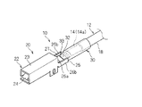
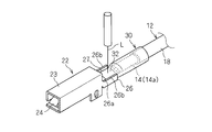
以下、実施形態に係る端子付電線及び端子付電線の製造方法について説明する。図1は端子付電線10を示す斜視図である。
Hereinafter, the manufacturing method of the electric wire with a terminal and electric wire with a terminal concerning an embodiment is explained. FIG. 1 is a perspective view showing a terminal-attached
<端子付電線について>
この端子付電線10は、電線12と端子20とを備える。
<About electric wires with terminals>
The terminal-attached
電線12は、芯線14と、芯線14を覆う被覆18とを備える。芯線14は、銅、銅合金、アルミニウム、アルミニウム等の線状の導体であり、ここでは、複数の素線が撚り合わされることによって芯線14が形成されている。芯線14は、単線によって構成されていてもよい。被覆18は、樹脂等の絶縁材料によって形成されている。被覆18は、例えば、芯線14の周りに軟化した樹脂を押出被覆等することによって形成される。この電線12の端部では、被覆18が剥離され、芯線14が露出している。芯線14のうち電線12の端部で露出している部分を、露出芯線部14aという場合がある。
The
端子20は、接続部22と、圧着部30とを備える。接続部22と圧着部30とは、それぞれ金属材料等の導電性材料によって形成されている。例えば、接続部22は、金属板材をプレス加工等することによって形成される。圧着部30は、絞り加工又は押出加工等によって形成された筒形状部材を、電線12の端部に圧着すべくプレス加工等することによって形成される。接続部22と圧着部30は、銅若しくは銅を主成分とする銅合金(黄銅等)によって構成された部材、あるいはそれらの部材に錫(Sn)メッキ若しくは錫合金のメッキが施された部材であることが考えられる。
The
芯線14と圧着部30とが異種金属で形成されている場合、芯線14と圧着部30との接続部分では、異種金属が接触した状態となっており、この部分に塩水等の電解液が付着すると、異種金属接触腐食が発生し得る。
When the
本実施形態に係る端子付電線10は、芯線14と圧着部30との接触部分に液体が付着しないようにするための構成を含んでおり、これにより、異種金属接触腐食を抑制することができる。このため、本実施形態に係る端子付電線10は、芯線14と圧着部30とが異種金属によって形成されている場合、例えば、芯線14がアルミニウム又はアルミニウム合金によって形成され、圧着部30が銅又は銅合金によって形成されている場合に適する。もっとも、金属に付着した液体は、当該金属に何らかの作用を及す恐れがあるため、本実施形態に係る端子付電線10は、芯線14と圧着部30とが異種金属によって形成されている場合に限らず、適用可能である。
The electric wire with
上記したように端子20は、接続部22と圧着部30とを備える。ここでは、接続部22とは圧着部30とは、直線状に連なっている。もっとも、接続部と圧着部との間で曲っていてもよい。
As described above, the
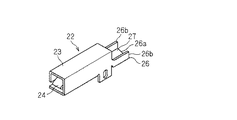
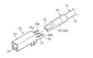
接続部22は、接続本体部23と、連結部26とを備える。
The
接続本体部23は、接続対象である相手側の導電性部分に接続される部分である。ここでは、接続本体部23は、相手側端子に接続される細長い端子形状に形成されている。より具体的には、接続本体部23は、筒形状(ここでは角筒形状)に形成される共に、内部にバネ接点部24が形成されている。すなわち、接続本体部23は、いわゆるメス端子形状に形成されている。そして、相手方端子のピン状又はタブ状の接続部が接続本体部23内に挿入接続されることで、バネ接点部24が相手方端子の接続部に接触し、もって、端子20と相手方端子とが電気的に接続される。接続本体部23は、ピン状又は端部状の形状、いわゆるオス端子形状に形成されていてもよい。また、接続本体部が、相手方端子に挿入接続可能な形状である必要はなく、例えば、円環状形状に形成され、ネジ止構造によって相手側の導電性部分に接続される形状(いわゆる丸端子形状)であってもよい。
The connection
連結部26は、接続本体部23の一端部から外方に延出するように連接されている。上記接続本体部23も連結部26も、一枚の板状金属材をプレス加工等することによって一体形成されている。
The connecting
連結部26には、圧着部30の一端部を受止め可能な連結用凹部27が形成されている。より具体的には、連結部26は、底部26aと、一対の側部26bとを備える。底部26aは、接続本体部23の底部の一端部より外方に延出している。一対の側部26bは、底部26aの両側部より突出している。一対の側部26bの端部は、接続本体部23の両側部のうち底部側の部分に連なっている。一対の側部26bが接続本体部23の両側部に連なっているため、本連結部26が接続本体部23に対して曲り難い。連結部26に、上方及び圧着部30とは反対側の部分で開口する、断面方形溝状の連結用凹部27が形成される。
The connecting
圧着部30は、元々上記接続部22とは別々に形成された部材であり、端子付電線10の製造工程の途中で接続部22に接合される。
The
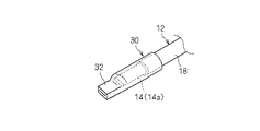
すなわち、圧着部30は、一端部が閉じられた筒形状に形成されている。ここでは、圧着部30の一端部は、プレス加工等によって圧潰された封止部32に形成されている。封止部32は、上記連結用凹部27に嵌め込み可能な形状、即ち、偏平な直方体形状に形成されている。封止部32の幅寸法は、連結用凹部27の幅寸法と同じに設定され、当該連結用凹部27に嵌め込み可能とされている。また、封止部32の厚み寸法は、連結部26に溶接できる程度に小さい。ここでは、封止部32の厚み寸法は、連結部26の側部26bの突出寸法よりも小さく、封止部32の上側からのレーザー光の照射等によって、当該封止部32を連結部26に溶接できるようになっている。
That is, the crimping
ここでは、封止部32が連結部26の連結用凹部27内に嵌め込まれた状態で、封止部32の上面側からレーザー光が照射されることによって、封止部32の幅方向に沿って延びる直線状の溶接部33が形成されている。この溶接部33は、封止部32と連結部26とを接合している。また、この封止部32では、圧壊によって圧着部30の一端部の内面同士が接触した偏平形状をなしており、溶接部33は、封止部32の一端部の接合された部分同士を溶接し、もって、封止部32をより確実に封止する役割を果す。
Here, the laser beam is irradiated from the upper surface side of the sealing
なお、封止部32は、上記圧壊によって封止されているので、これに加えて、溶接部33によって封止することは必須ではない。
In addition, since the sealing
また、圧着部30の一端部が圧壊によって封止されていることは必須ではない。例えば、圧着部30を形成するための筒状部材として、当初から一端部が閉塞された底付き筒状部材を用いてもよい。また、樹脂その他の封止部材によって、筒状部材の一端部が封止されてもよい。
Moreover, it is not essential that the one end part of the crimping | compression-
さらに、圧着部30と接続部22とを接合する構成として、上記例に限られず、抵抗溶接、超音波溶接、半田付、圧着部又は接続部側の部分をかしめることによるかしめ接合等が採用されてもよい。
Further, the configuration for joining the crimping
上記圧着部30には、露出芯線部14aが形成された電線12の端部が、上記圧着部30のうち封止部32とは反対側の開口を通って圧着部30内に挿入されている。なお、露出芯線部14aの長さ寸法は、圧着部30内の収容空間の長さ寸法よりも短く、従って、電線12の端部を圧着部30内に収容すると、その電線12の被覆18の端部も圧着部30の開口側端部内に配設される。このように、露出芯線部14aが圧着部30内に収容された状態で、圧着部30の他端部が被覆18の端部を覆うと共に、圧着部30が露出芯線部14aに圧着されている。
In the crimping
好ましくは、圧着部30の他端部も、被覆18の端部の外周囲に接触するようにかしめられる。或は、接着剤、封止剤等によって、圧着部30他端部と被覆18の端部の外周囲との間が封止される。ここでは、前者の例で説明する。
Preferably, the other end portion of the crimping
なお、上記圧着部30は、その周方向において継目無く連続的に繋がる筒形状に形成されていることが好ましい。ここでも、圧着部30は、そのような継目が無い筒形状に形成されている。
In addition, it is preferable that the said crimping | compression-
これにより、露出芯線部14aは、圧着部30内において封止された状態に収容される。
Thereby, the exposed
<端子付電線の製造方法について>
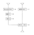
図2〜図9は端子付電線10を製造する各工程を示す説明図であり、図10は端子付電線10の製造方法例を示す工程図である。
<About manufacturing method of electric wire with terminal>
2-9 is explanatory drawing which shows each process of manufacturing the
まず、ステップS1に示すように、接続部22を形成するための加工を実施する。すなわち、金属板材等をプレス加工等して、接続部22を製造しておく(図2参照)。
First, as shown in step S1, a process for forming the
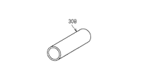
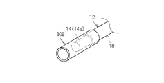
これの前後又は並行して、ステップS2に示すように、上記圧着部30を形成するための筒形状部品30Bの形成加工を実施する(図3参照)。筒形状部品30Bは、例えば、絞り加工又は押出加工によって形成された長尺筒部品を、圧着部30を形成するために必要な長さ寸法に切断することで得ることができる。
Before and after or in parallel with this, as shown in step S2, a forming process of the cylindrical part 30B for forming the crimping
絞り加工又は押出加工によって形成された長尺筒部品は、その外周部に継目が無い部品であるため、筒形状部品30Bも、その外周部に継目が無い部品として製造される。もっとも、筒形状部品30Bは、板状部材を丸めてその外周部でレーザー溶接等によって接合した部品として製造されてもよい。この場合であっても、接続部22とは別体とされた状態で当該加工を施せるため、従来技術と比べると、その加工は容易である。
Since the long cylindrical part formed by drawing or extruding is a seamless part on the outer periphery thereof, the cylindrical part 30B is also manufactured as a seamless part on the outer peripheral part. But the cylindrical part 30B may be manufactured as a part which rounded the plate-shaped member and joined by laser welding etc. in the outer peripheral part. Even in this case, since the processing can be performed in a state separated from the
また、ここでは、筒形状部品30Bは、円筒形状に形成されている。筒形状部品30Bは、その他、楕円筒形状、多角形筒形状等であってもよい。筒形状部品30Bが円筒形状であれば、電線12の被覆18の外周全体に密接させやすいというメリットがある。
Here, the cylindrical part 30B is formed in a cylindrical shape. In addition, the cylindrical part 30B may have an elliptical cylindrical shape, a polygonal cylindrical shape, or the like. If cylindrical part 30B is cylindrical, there exists a merit that it is easy to make it close to the whole outer periphery of the coating | cover 18 of the
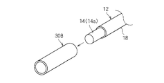
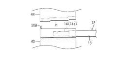
そして、ステップS3に示すように、筒形状部品30B内に、電線12の端部の露出芯線部14aを収容する(工程(a)、図4及び図5参照)。なお、露出芯線部14aの長さ寸法は、筒形状部品30Bの収容空間の長さ寸法よりも短く、従って、電線12の端部を筒形状部品30B内に収容すると、その電線12の被覆18の端部も筒形状部品30Bの開口側端部内に配設される。また、筒形状部品30Bの内径寸法は、電線12の外形寸法よりも大きい。従って、電線12の被覆18部分も、筒形状部品30Bに挿入することができる。
And as shown to step S3, the exposed
このように露出芯線部14aを筒形状部品30B内に収容した状態で、ステップS4に示すように、圧着用の下金型40及び上金型44等を用いて、筒形状部品30Bのうち露出芯線部14aを収容した部分が、当該露出芯線部14aに圧着するようにかしめられる(工程(b)、図6及び図7参照)。また、筒形状部品30Bの他端部も被覆18の端部を覆ってその外周囲に接触するようにかしめられる。さらに、筒形状部品30Bの一端部も封止するようにかしめられ、上記封止部32が形成される(工程(d))。
In the state where the exposed
なお、上記下金型40及び上金型44には、筒形状部品30Bを、封止部32に形成するための断面方形状の金型面、及び、露出芯線部14aにかしめるための金型面等が形成されている。
Note that the
これにより、露出芯線部14aは、筒形状部品30Bによって形成された圧着部30内において封止された状態に収容される。
Thereby, the exposed
なお、封止部32は、筒形状部品30Bを電線12の端部に取付ける前又は後に形成されていてもよい。例えば、封止部32は、圧着部30を接続部22に接合する際に又は接合後に形成されてもよい。
In addition, the sealing
次に、ステップS5に示すように、圧着部30を接続部22に接合する(工程(c)、図8及び図9参照)。
Next, as shown in step S5, the crimping
この際、圧着部30の封止部32を、連結部26の連結用凹部27内に嵌め込んだ状態で、圧着部30を接続部22に接合する作業を容易に実施できる。もっとも、封止部32が連結用凹部27に嵌め込まれることは必須ではない。他の治具によって接続部22と圧着部30とを位置決めして両者を接触させた状態で接合を行ってもよい。
At this time, the operation of joining the crimping
接合は、ここでは、レーザー溶接によって行う。すなわち、連結用凹部27に封止部32を嵌め込んで、連結部26の底部26a上に偏平な封止部32を重ね合せた状態で、封止部32の上面にレーザー光Lを照射させる。レーザー光は、連結部26の底部26aの下面側から照射されてもよいし、連結部26の側部26bの外面側から照射されてもよい。また、レーザー光は、封止部32に対して線状の経路に沿って照射されてもよいし、スポット状に複数点に照射されてよい。また、上記接合は、レーザー溶接によって形成されることが好ましいが、その他、抵抗溶接、超音波溶接、半田付等によってなされてもよい。
Here, the joining is performed by laser welding. That is, the sealing
封止部32をより確実に封止するためには、封止部32の一側部から他側部に向うように溶接部33が形成されていることが好ましい。ここでは、封止部32を幅方向に横切るように直線状の溶接部33が形成されている。溶接部33は、好ましくは、封止部32の幅方向全体に亘って形成されている。
In order to seal the sealing
以上により端子付電線10が製造される。
The
このように構成された端子付電線10及びその製造方法によると、圧着部30は、接続本体部23に接合されている。このため、接続部22に接合する前に、圧着部30又は圧着部30を形成するための筒形状部品30Bを形成することができ、それらを容易に形成できる。
According to the thus configured terminal-attached
特に、ここでは、圧着部30を形成するための筒形状部品30Bとして、その周方向において継目無く連続的に繋がる筒形状に形成されたものを用いている。そして、圧着部30も、その周方向において継目無く連続的に繋がる筒形状をなしている。このため、圧着部30内において、露出芯線部14aをより確実に封止できる。
In particular, here, as the cylindrical part 30B for forming the pressure-
また、従来技術では、板状基材を、プレス加工によって丸めて筒状に形成し、その筒状部の端縁同士を溶接し、これにより、筒状の圧着部を形成していた。この従来技術では、露出芯線部14aを封止するためには、筒状部の端縁同士を精度よく溶接する必要があった。本実施形態では、そのような溶接作業をなくすることができるため、筒形状部品30B及び圧着部30を容易に形成できる。
Further, in the prior art, the plate-like base material is rounded and formed into a cylindrical shape by pressing, and the edges of the cylindrical portion are welded together, thereby forming a cylindrical crimping portion. In this prior art, in order to seal the exposed
しかも、従来技術では、また、筒状部の端縁同士を溶接した溶接部分が、電線に対して損傷を与える恐れがある。しかしながら、本実施形態では、そのような溶接部分自体をなくすることができるため、電線に対する損傷を抑制できる。 In addition, in the prior art, a welded portion where the edges of the cylindrical portion are welded may cause damage to the electric wire. However, in this embodiment, since such a welding part itself can be eliminated, damage to the electric wire can be suppressed.
また、例えば、従来技術では、端子接続部と圧着部とが一体形成されているため、接続部形状として、端子形状或はサイズに応じてN種類のタイプ(Nは自然数)が必要で、圧着部形状として、電線サイズ等に応じてM種類のタイプが必要であるとすると(Mは自然数)、端子として最大N×M種類のタイプを準備しておく必要がある。これに対して、本端子20では、接続部22に対して圧着部30が接合された構成であるため、N種類の接続部22と、M種類の圧着部30とを準備しておけばよい。つまり、N+M種類の部品によって、最大N×M種類の端子タイプに対応可能である。このため、部品種類数の削減が可能となる。
Further, for example, in the prior art, since the terminal connection portion and the crimping portion are integrally formed, N types (N is a natural number) are required as the shape of the connection portion depending on the terminal shape or size. Assuming that M types of part shapes are required according to the wire size and the like (M is a natural number), it is necessary to prepare a maximum of N × M types as terminals. On the other hand, in this terminal 20, since the crimping | compression-
また、封止部32が連結部26の連結用凹部27に嵌り込んでいるため、接続部22と圧着部30との接合作業を容易に行えると共に、それらの接合状態をより確実に維持できる。
In addition, since the sealing
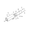
{変形例}
なお、溶接部33は、金属を溶かして接合した部分であるあるため、その他の部分よりも強度的に劣ってしまう恐れがある。そこで、図11に示すように、溶接部133を、少なくとも一部で曲りつつ、封止部32の一側部から他側部に向う形状とすることで、非直線形状に形成するとよい。つまり、強度的に劣る部分が直線的に存在しなくなるようにするとよい。
{Modifications}
In addition, since the
ここでは、図11に示す例では、溶接部133は、V字状に曲るように形成されている。より具体的には、溶接部133は、封止部32の幅方向中央部で、接続本体部23側に向け凸となるように曲るV字状とされている。その他、溶接部は、U字状に形成されていてもよいし、ジグザグに形成されていてもよいし、階段状に形成されていてもよい。
Here, in the example shown in FIG. 11, the welded
いずれにせよ、溶接部が、少なくとも一部で曲りつつ、封止部32の一側部から他側部に向う形状とすることで、端子20が溶接部133で曲り難くなる。
In any case, it is difficult for the terminal 20 to be bent at the welded
なお、上記実施形態及び各変形例で説明した各構成は、相互に矛盾しない限り適宜組合わせることができる。 In addition, each structure demonstrated in the said embodiment and each modification can be suitably combined unless it mutually contradicts.
以上のようにこの発明は詳細に説明されたが、上記した説明は、すべての局面において、例示であって、この発明がそれに限定されるものではない。例示されていない無数の変形例が、この発明の範囲から外れることなく想定され得るものと解される。 As described above, the present invention has been described in detail. However, the above description is illustrative in all aspects, and the present invention is not limited thereto. It is understood that countless variations that are not illustrated can be envisaged without departing from the scope of the present invention.
10 端子付電線
12 電線
14 芯線
14a 露出芯線部
18 被覆
20 端子
22 接続部
23 接続本体部
26 連結部
27 連結用凹部
30 圧着部
30B 筒形状部品
32 封止部
33,133 溶接部
DESCRIPTION OF
Claims (5)
接続部と、前記接続部に接合された圧着部とを含み、前記圧着部は一端部が閉じられた筒形状に形成されており、露出した前記芯線が前記圧着部内に収容された状態で、前記圧着部の他端部が前記被覆の端部を覆うと共に前記圧着部が露出した前記芯線に圧着されて、前記電線の端部に取付けられた端子と、
を備える端子付電線。 An electric wire including a core wire and a coating covering the core wire, wherein the core wire is exposed at an end;
Including a connection part and a crimping part joined to the connection part, the crimping part is formed in a cylindrical shape with one end closed, and the exposed core wire is accommodated in the crimping part, The other end of the crimping part covers the end of the covering and is crimped to the core wire from which the crimping part is exposed, and a terminal attached to the end of the wire,
An electric wire with a terminal.
前記圧着部は、その周方向において継目無く連続的に繋がる筒形状に形成されている、端子付電線。 It is an electric wire with a terminal according to claim 1,
The crimp portion is a terminal-attached electric wire that is formed in a tubular shape that is continuously connected in the circumferential direction.
前記接続部は、接続対象との接続に供される接続本体部と、前記接続本体部に連設されると共に前記圧着部の一端部を受止め可能な連結用凹部が形成された連結部とを含み、
前記圧着部の一端部が前記連結用凹部に嵌め込まれた状態で、前記連結部に接合されている、端子付電線。 It is an electric wire with a terminal according to claim 1 or claim 2,
The connection portion includes a connection main body provided for connection with a connection target, a connection portion provided continuously with the connection main body portion, and formed with a connection concave portion capable of receiving one end of the crimping portion. Including
A terminal-attached electric wire joined to the connecting portion in a state where one end portion of the crimping portion is fitted in the connecting concave portion.
前記圧着部の一端部と前記接続部との接合部分に、少なくとも一部で曲りつつ、前記圧着部の一側部から他側部に向う溶接部が形成されている、端子付電線。 It is an electric wire with a terminal given in any 1 paragraph of Claims 1-3,
A terminal-attached electric wire in which a welded portion from one side portion to the other side portion of the crimping portion is formed at a part of the joining portion between the one end portion of the crimping portion and the connection portion.
(b)前記筒形状部品の他端部が前記電線の被覆の端部を覆った状態で、前記筒形状部品を露出した前記芯線に圧着して圧着部を形成する工程と、
(c)前記圧着部を、接続部に接合する工程と、
(d)前記筒形状部品の一端部を閉じる工程と、
を備える端子付電線の製造方法。 (a) storing the core wire exposed at the end of the electric wire in the cylindrical part;
(b) in a state where the other end portion of the cylindrical part covers the end of the coating of the electric wire, and a step of pressing the cylindrical part to the exposed core wire to form a crimped part;
(c) bonding the pressure-bonding part to the connection part;
(d) a step of closing one end of the cylindrical part;
The manufacturing method of the electric wire with a terminal provided with.
Priority Applications (1)
| Application Number | Priority Date | Filing Date | Title |
|---|---|---|---|
| JP2014177600A JP2016051663A (en) | 2014-09-02 | 2014-09-02 | Electric wire with terminal and method of manufacturing electric wire with terminal |
Applications Claiming Priority (1)
| Application Number | Priority Date | Filing Date | Title |
|---|---|---|---|
| JP2014177600A JP2016051663A (en) | 2014-09-02 | 2014-09-02 | Electric wire with terminal and method of manufacturing electric wire with terminal |
Publications (1)
| Publication Number | Publication Date |
|---|---|
| JP2016051663A true JP2016051663A (en) | 2016-04-11 |
Family
ID=55659017
Family Applications (1)
| Application Number | Title | Priority Date | Filing Date |
|---|---|---|---|
| JP2014177600A Pending JP2016051663A (en) | 2014-09-02 | 2014-09-02 | Electric wire with terminal and method of manufacturing electric wire with terminal |
Country Status (1)
| Country | Link |
|---|---|
| JP (1) | JP2016051663A (en) |
Cited By (2)
| Publication number | Priority date | Publication date | Assignee | Title |
|---|---|---|---|---|
| KR101851897B1 (en) * | 2016-06-09 | 2018-04-24 | 델피 테크놀로지스, 엘엘씨. | Radio frequency coaxial connector assembly and method of maufacturing same |
| WO2021049210A1 (en) * | 2019-09-12 | 2021-03-18 | 株式会社オートネットワーク技術研究所 | Terminal fitting, wire with terminal, and terminal system |
-
2014
- 2014-09-02 JP JP2014177600A patent/JP2016051663A/en active Pending
Cited By (2)
| Publication number | Priority date | Publication date | Assignee | Title |
|---|---|---|---|---|
| KR101851897B1 (en) * | 2016-06-09 | 2018-04-24 | 델피 테크놀로지스, 엘엘씨. | Radio frequency coaxial connector assembly and method of maufacturing same |
| WO2021049210A1 (en) * | 2019-09-12 | 2021-03-18 | 株式会社オートネットワーク技術研究所 | Terminal fitting, wire with terminal, and terminal system |
Similar Documents
| Publication | Publication Date | Title |
|---|---|---|
| JP6020436B2 (en) | Terminal for connecting electric wire and electric wire connecting structure of the terminal | |
| US9281574B2 (en) | Crimp terminal, connection structural body, connector, wire harness, method of manufacturing crimp terminal, and method of manufacturing connection structural body | |
| EP2871718B1 (en) | Pressure-fixing terminal, connecting structure and connector | |
| KR101543547B1 (en) | Crimp terminal, wire harness, and method for manufacturing crimp terminal | |
| CN104272535A (en) | crimp terminal production method, crimp terminal, and wire harness | |
| WO2014129606A1 (en) | Crimp contact, method for producing crimp contact, wire connecting structure, and method for producing wire connecting structure | |
| JP6422442B2 (en) | Connection terminal and wire assembly | |
| WO2011118416A1 (en) | Electric wire with terminal fitting and production method for same | |
| WO2016017013A1 (en) | Method for joining terminal and electric wire and electric wire connection terminal | |
| US10122095B2 (en) | Crimp terminal, connecting structure, manufacturing method of the crimp terminal, and laser welding method | |
| JP6074285B2 (en) | Terminal and electric wire joining method and electric wire connection terminal | |
| JP2016051663A (en) | Electric wire with terminal and method of manufacturing electric wire with terminal | |
| JP6422213B2 (en) | Connection terminal and connection structure including the connection terminal | |
| JP2014164927A (en) | Crimp terminal and connection structure | |
| JP6219039B2 (en) | Welding method, tube terminal, tube terminal manufacturing method, electric wire connection structure, and electric wire connection structure manufacturing method | |
| JP2014164870A (en) | Crimp terminal, connection structure, connector and method of manufacturing crimp terminal | |
| JP2014164926A (en) | Crimp terminal and connection structure | |
| WO2016031795A1 (en) | Method for manufacturing terminal-equipped electrical wires | |
| JP7244262B2 (en) | Aluminum wire connection method and aluminum wire connection structure | |
| JP6133080B2 (en) | Crimp terminal, crimp terminal manufacturing method, electric wire connection structure, and electric wire connection structure manufacturing method | |
| JP6339451B2 (en) | Terminal, connection structure, wire harness, and terminal manufacturing method | |
| JP2016046176A (en) | Welded joint, terminal provided with the welded joint, method for producing welded joint, and method for producing terminal | |
| JP2015125978A (en) | Wire harness, method of connecting coated lead wire, and wire harness structure | |
| JP6200366B2 (en) | Connection structure, wire harness, and method of manufacturing connection structure | |
| JP2016046029A (en) | Terminal and wire with terminal |