JP2016019343A - Exterior member for wire harness, and wire harness - Google Patents
Exterior member for wire harness, and wire harness Download PDFInfo
- Publication number
- JP2016019343A JP2016019343A JP2014140141A JP2014140141A JP2016019343A JP 2016019343 A JP2016019343 A JP 2016019343A JP 2014140141 A JP2014140141 A JP 2014140141A JP 2014140141 A JP2014140141 A JP 2014140141A JP 2016019343 A JP2016019343 A JP 2016019343A
- Authority
- JP
- Japan
- Prior art keywords
- exterior member
- wire harness
- fixing
- thin
- portions
- Prior art date
- Legal status (The legal status is an assumption and is not a legal conclusion. Google has not performed a legal analysis and makes no representation as to the accuracy of the status listed.)
- Pending
Links
Images


Abstract
Description
本発明は、ワイヤハーネス用の外装部材と、この外装部材を構成に含んでなるワイヤハーネスとに関する。 The present invention relates to an exterior member for a wire harness and a wire harness including the exterior member in its configuration.
例えばハイブリッド自動車や電気自動車に搭載される高電圧の機器間を電気的に接続するためとしてワイヤハーネスが用いられる。近年の動向を見ると、ワイヤハーネスは、配索スペースに配慮された構成及び構造のものが採用される。 For example, a wire harness is used to electrically connect high voltage devices mounted on a hybrid vehicle or an electric vehicle. Looking at trends in recent years, wire harnesses having a configuration and structure that take into account the wiring space are adopted.
下記特許文献1に開示されたワイヤハーネスは、導電路と、この導電路を保護するための合成樹脂製の外装部材とを備えて構成される。外装部材は、ワイヤハーネスを三次元的な複雑なスペースに配索するために、蛇腹管形状の可撓管部と、ストレート管形状のストレート管部とを有する。外装部材は、これら可撓管部とストレート管部とを連続させるようにして樹脂成形される。このような外装部材を採用すれば、三次元的な複雑なスペースであってもワイヤハーネスの配策が可能になる。 The wire harness disclosed in the following Patent Document 1 includes a conductive path and a synthetic resin exterior member for protecting the conductive path. The exterior member has a bellows tube-shaped flexible tube portion and a straight tube-shaped straight tube portion in order to route the wire harness in a three-dimensional complex space. The exterior member is resin-molded so that the flexible tube portion and the straight tube portion are continuous. If such an exterior member is employed, the wiring harness can be arranged even in a three-dimensional complicated space.
上記従来のワイヤハーネスにあっては、樹脂製の外装部材を採用することから、金属パイプからなる外装部材のワイヤハーネスと比べて軽量化を図ることができるという効果を奏する。しかしながら、近年では更なる軽量化の要望があり、そのためには、外装部材としての強度を確保しつつ軽量化を図らなければならないと本願発明者は考える。 In the conventional wire harness, since the resin exterior member is employed, an effect that the weight can be reduced as compared with the wire harness of the exterior member made of the metal pipe is achieved. However, in recent years, there has been a demand for further weight reduction, and for this purpose, the inventor of the present application thinks that weight reduction must be achieved while ensuring strength as an exterior member.
本発明は、上記した事情に鑑みてなされたもので、強度を確保しつつ軽量化を図ることが可能なワイヤハーネス用の外装部材、及びワイヤハーネスを提供することを課題とする。 This invention is made | formed in view of an above-described situation, and makes it a subject to provide the exterior member for wire harnesses which can aim at weight reduction, ensuring a strength, and a wire harness.
上記課題を解決するためになされた請求項1に記載の本発明のワイヤハーネス用の外装部材は、導電路を挿通して保護するために樹脂成形にて管体形状に形成されるワイヤハーネス用の外装部材において、当該外装部材は前記ワイヤハーネスを所定位置に固定するための固定部又は固定部材が外側に複数設けられるものであり、且つ、隣り合う前記固定部又は前記固定部材の間隔あるいは配置に応じて内側に薄肉部が形成されることを特徴とする。 The wire harness exterior member of the present invention according to claim 1 made to solve the above problems is for a wire harness formed into a tubular shape by resin molding in order to insert and protect a conductive path. In the exterior member, the exterior member is provided with a plurality of fixing portions or fixing members for fixing the wire harness at a predetermined position on the outside, and the interval or arrangement of the adjacent fixing portions or the fixing members. A thin-walled portion is formed on the inner side according to the above.
請求項2に記載の本発明は、請求項1に記載のワイヤハーネス用の外装部材において、当該外装部材は可撓管部とストレート管部とを有し、少なくとも該ストレート管部の前記内側に前記薄肉部が形成されることを特徴とする。 According to a second aspect of the present invention, in the exterior member for a wire harness according to the first aspect, the exterior member has a flexible tube portion and a straight tube portion, and at least inside the straight tube portion. The thin portion is formed.
以上のような特徴を有する本発明のワイヤハーネス用の外装部材によれば、薄肉部を有する外装部材であり、この薄肉部は例えば隣り合う固定部又は固定部材の間隔が狭くなる部分に合わせて形成される。薄肉部の形成により外装部材の肉厚が薄くなるが、固定部又は固定部材が固定対象に固定された状態になれば強度低下分が補われ、結果、外装部材として必要な強度を確保することができる。従って、上記間隔が狭くなる部分で外装部材の軽量化を図ることができる。尚、本発明の外装部材によれば、内側に薄肉部が形成されることから、軽量化のために外観が変わることがなく、結果、配策作業や配策スペースに支障を来すことはない。この他、本発明の外装部材によれば、軽量化に伴って樹脂材料の低減を図ることもできる。すなわち、コスト低減を図ることもできる。 According to the exterior member for a wire harness of the present invention having the above-described features, the exterior member has a thin portion, and this thin portion is adapted to, for example, an adjacent fixing portion or a portion where the interval between the fixing members is narrow. It is formed. The thickness of the exterior member is reduced by the formation of the thin part, but if the fixed part or the fixed member is fixed to the object to be fixed, the decrease in strength is compensated, and as a result, the necessary strength as the exterior member is secured. Can do. Accordingly, it is possible to reduce the weight of the exterior member at the portion where the interval is narrowed. In addition, according to the exterior member of the present invention, since the thin portion is formed on the inner side, the appearance does not change for weight reduction, and as a result, it may hinder the routing work and the routing space. Absent. In addition, according to the exterior member of the present invention, the resin material can be reduced as the weight is reduced. That is, cost reduction can be achieved.
また、上記課題を解決するためになされた請求項3に記載の本発明のワイヤハーネスは、請求項1又は2に記載のワイヤハーネス用の外装部材と、該外装部材に挿通される導電路と、前記外装部材の外側に複数設けられる固定部又は固定部材とを備えることを特徴とする。
Moreover, the wire harness of this invention of
以上のような特徴を有する本発明のワイヤハーネスによれば、外装部材における薄肉部の分だけ軽量化される。 According to the wire harness of the present invention having the above-described features, the weight is reduced by the thin portion of the exterior member.
請求項1、2に記載された本発明によれば、強度を確保しつつ軽量化を図ることが可能な外装部材を提供することができるという効果を奏する。また、請求項3に記載された本発明によれば、強度を確保しつつ軽量化を図ることが可能なワイヤハーネスを提供することができるという効果を奏する。
According to the first and second aspects of the present invention, there is an effect that it is possible to provide an exterior member capable of reducing the weight while securing the strength. Further, according to the present invention described in
ワイヤハーネスは、外装部材と、この外装部材に挿通される導電路と、ワイヤハーネスを所定位置に固定するための固定部又は固定部材とを備えて構成される。外装部材は、導電路を挿通して保護するために管体形状に形成される。外装部材は、樹脂成形品であって、内側には薄肉部が形成される。薄肉部は、隣り合う固定部又は固定部材の間隔が狭い部分に合わせて配置形成される。薄肉部は、軽量化を図る部分として形成される。 The wire harness includes an exterior member, a conductive path inserted through the exterior member, and a fixing portion or a fixing member for fixing the wire harness at a predetermined position. The exterior member is formed in a tubular shape in order to insert and protect the conductive path. The exterior member is a resin molded product, and a thin portion is formed inside. The thin portion is disposed and formed in accordance with a portion where the interval between adjacent fixing portions or fixing members is narrow. A thin part is formed as a part aiming at weight reduction.
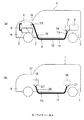
以下、図面を参照しながら実施例1を説明する。図1は本発明のワイヤハーネスに係る図であり、(a)は高電圧のワイヤハーネスの配索状態を示す模式図、(b)は(a)とは別のワイヤハーネスの配索状態を示す模式図である。また、図2は図1(a)のワイヤハーネスの構成及び固定状態を示す概要図、図3は図2の外装部材の構成を示す概要図、図4は図3の外装部材の要部断面図である。 Embodiment 1 will be described below with reference to the drawings. FIG. 1 is a diagram related to a wire harness according to the present invention, in which (a) is a schematic diagram illustrating a wiring state of a high-voltage wire harness, and (b) illustrates a wiring state of a wire harness different from (a). It is a schematic diagram shown. 2 is a schematic diagram showing the configuration and fixing state of the wire harness of FIG. 1A, FIG. 3 is a schematic diagram showing the configuration of the exterior member of FIG. 2, and FIG. 4 is a cross-sectional view of the main part of the exterior member of FIG. FIG.
本実施例においては、ハイブリッド自動車(電気自動車等であってもよい)に配索されるワイヤハーネスに対し本発明を採用する。 In the present embodiment, the present invention is adopted for a wire harness routed in a hybrid vehicle (which may be an electric vehicle or the like).
図1(a)において、引用符号1はハイブリッド自動車を示す。ハイブリッド自動車1は、エンジン2及びモータユニット3の二つの動力をミックスして駆動する車両であって、モータユニット3にはインバータユニット4を介してバッテリー5(電池パック)からの電力が供給される。エンジン2、モータユニット3、及びインバータユニット4は、本実施例において前輪等がある位置のエンジンルーム6に搭載される。また、バッテリー5は、後輪等がある自動車後部7に搭載される(エンジンルーム6の後方に存在する自動車室内に搭載してもよい)。
In FIG. 1A, reference numeral 1 indicates a hybrid vehicle. The hybrid vehicle 1 is a vehicle that mixes and drives two powers of an engine 2 and a
モータユニット3とインバータユニット4は、高圧の(高電圧用の)ワイヤハーネス8により接続される。また、バッテリー5とインバータユニット4も高圧のワイヤハーネス9により接続される。ワイヤハーネス9は、この中間部10が車両床下11に配索される。また、車両床下11に沿って略平行に配索される。車両床下11は、公知のボディであるとともに所謂パネル部材であって、所定位置には貫通孔が形成される。この貫通孔には、ワイヤハーネス9が水密に挿通される。
The
ワイヤハーネス9とバッテリー5は、このバッテリー5に設けられるジャンクションブロック12を介して接続される。ジャンクションブロック12には、ワイヤハーネス9の後端側のハーネス端末13に配設されたシールドコネクタ14等の外部接続手段が電気的に接続される。また、ワイヤハーネス9とインバータユニット4は、前端側のハーネス端末13に配設されたシールドコネクタ14等の外部接続手段を介して電気的に接続される。
The
モータユニット3は、モータ及びジェネレータを含んで構成される。また、インバータユニット4は、インバータ及びコンバータを構成に含んで構成される。モータユニット3は、シールドケースを含むモータアッセンブリとして形成される。また、インバータユニット4もシールドケースを含むインバータアッセンブリとして形成される。バッテリー5は、Ni−MH系やLi−ion系のものであって、モジュール化することによりなる。尚、例えばキャパシタのような蓄電装置を使用することも可能である。バッテリー5は、ハイブリッド自動車1や電気自動車に使用可能であれば特に限定されないのは勿論である。
The
図1(b)において、引用符号15はワイヤハーネスを示す。ワイヤハーネス15は、低圧の(低電圧用の)ものであって、ハイブリッド自動車1における自動車後部7の低圧バッテリー16と、自動車前部17に搭載される補器18(機器)とを電気的に接続するために備えられる。ワイヤハーネス15は、図1(a)のワイヤハーネス9と同様に、車両床下11を通って配索される(一例である。車室側を通って配索されてもよい)。
In FIG. 1B,
図1(a)及び(b)に示す如く、ハイブリッド自動車1には、高圧のワイヤハーネス8、9及び低圧のワイヤハーネス15が配策される。本発明は、いずれのワイヤハーネスであっても適用可能であるが、代表例としてワイヤハーネス9を挙げて以下に説明をする。
As shown in FIGS. 1A and 1B, high-voltage wire harnesses 8 and 9 and a low-
図1(a)及び図2において、車両床下11を通って配索される長尺なワイヤハーネス9は、ハーネス本体19と、このハーネス本体19の両端、すなわちハーネス端末13にそれぞれ配設されるシールドコネクタ14(外部接続手段)とを備えて構成される。また、ワイヤハーネス9は、車両の所定位置に固定するための複数の固定部材20(例えばクランプ等)と、水分の浸入を規制するための止水部材21、22(例えばグロメットやブーツ)とを備えて構成される。
In FIG. 1A and FIG. 2, the
図2において、ワイヤハーネス9は、上記の如く複数の固定部材20にて固定される。ここで固定部材20を引用符号20a〜20dで示すと、図2ではワイヤハーネス9が固定部材20a〜20dにて車両の固定対象23に固定される(一例であり図2の固定数に限定されないものとする)。尚、固定部材20の構成及び構造に関しては後述する。
In FIG. 2, the
固定部材20aは、後述する外装部材24の短いストレート管部31に設けられる。また、固定部材20b〜20dは、外装部材24の長いストレート管部32の所定位置にそれぞれ設けられる。固定部材20a及び固定部材20bは、これらの間に外装部材24の後述する可撓管部28が存在した状態で配設される(取り付けられる)。固定部材20a及び固定部材20bは、可撓管部28が介在するものの比較的狭い間隔で配設される。逆に、固定部材20b及び固定部材20cは、大きく離れるような間隔で配設される。この他、固定部材20c及び固定部材20dは、最も狭い間隔で配設される。以上のように、固定部材20a〜20dは、間隔が異なった状態で配設される。
The fixing
後述する外装部材24には、本発明に係る特徴的な部分が形成される。この特徴的な部分は、固定部材20a〜20dの間隔や配置に応じて形成される。
A characteristic portion according to the present invention is formed in an
ハーネス本体19は、本発明に係る外装部材24と、この外装部材24に収容保護される高圧導電路25(導電路)とを備えて構成される。尚、外装部材24に関し、低圧のワイヤハーネス15を一緒に収容保護するような構成及び構造のものを採用してもよい(上記低圧のワイヤハーネス15は、ハーネス本体26と、このハーネス本体26の両端に配設されるコネクタ27とを備えて構成される(図1(b)参照))。
The
図2及び図3において、外装部材24は、エアブロー方式又はバキューム方式による装置を用いた樹脂成形にて一本の真っ直ぐな管体形状のものに形成される(使用前は真っ直ぐである)。このような外装部材24には、可撓性を有する可撓管部28〜30と、ストレートに配索する部分としてのストレート管部(短いストレート管部31、長いストレート管部32)とが形成される。本実施例においては、図中左側から(ワイヤハーネス9の前端側から)可撓管部28、短いストレート管部31、可撓管部29、長いストレート管部32、可撓管部30となるように可撓管部とストレート管部とが交互に配置される。
2 and 3, the
可撓管部28〜30は、固定対象23(ワイヤハーネス配索先)の曲げ位置及び曲げ長さに合わせて配置形成される。可撓管部28〜30の長さは一定でなく、固定対象23に合わせて必要な長さでそれぞれ形成される。このような可撓管部28〜30は、ワイヤハーネス9の梱包状態や輸送時、車両への経路配索時に、それぞれ所望の角度で撓ませられる。可撓管部28〜30は、撓ませて曲げ形状にすることができるとともに、図3に示すような真っ直ぐな元の状態(樹脂成形時の状態)に戻すことも当然にできるように形成される。
The
可撓管部28〜30は、本実施例において蛇腹管形状に形成される(可撓性を有すれば形状は特に限定されない)。具体的には、周方向の蛇腹凹部33及び蛇腹凸部34を有するとともに、これら蛇腹凹部33及び蛇腹凸部34が管軸方向に交互に連続するように形成される。
The
図2ないし図4において、短いストレート管部31及び長いストレート管部32は、可撓管部28〜30のような可撓性を持たない部分として形成される。また、短いストレート管部31及び長いストレート管部32は、梱包状態や輸送時、経路配索時において曲がらない部分としても形成される(曲がらない部分とは、可撓性を積極的に持たせない部分という意味である)。短いストレート管部31及び長いストレート管部32は、真っ直ぐのびた管体形状に形成される。
2 to 4, the short
短いストレート管部31及び長いストレート管部32の外面には、固定部材20a〜20dを取り付ける部分としての固定部材取付部35が複数形成される。固定部材取付部35は、短いストレート管部31に一つ、長いストレート管部32に三つ形成される(数は一例である)。固定部材取付部35は、一対の移動規制部36と、着脱部37とを含んで構成される(取り付けの部分であれば図示構成に限らないものとする)。一対の移動規制部36は、環状のフランジ形状に形成される。一対の移動規制部36は、着脱部37の両側に配置形成される。尚、固定部材取付部35の配置は、固定部材20a〜20dの上記間隔と同様の内容であり説明を省略する。
A plurality of fixing
短いストレート管部31及び長いストレート管部32の内面には、本発明の特徴部分である薄肉部38〜40が形成される。薄肉部38〜40は、短いストレート管部31及び長いストレート管部32の肉厚を内側から薄くすることにより形成される。このような薄肉部38〜40は、固定部材20a〜20dの間隔や配置に応じて形成される。薄肉部38〜40は、肉厚を薄くして形成されることから、軽量化を図ることができる部分として有効である。薄肉部38〜40は、外装部材24に係る樹脂成形の装置を適宜制御することにより、具体的には樹脂成形速度や樹脂材の供給量を制御することにより形成される。
On the inner surfaces of the short
薄肉部38〜40は、固定部材20a〜20dの間隔や配置に応じて形成範囲が設定される。この形成範囲は、固定対象23への固定部材20a〜20dの固定を行った状態で外装部材24の必要強度を確保できるような範囲に設定される。
The formation range of the
薄肉部38は、固定部材20aが取り付けられる短いストレート管部31の内面全体に形成される。本実施例においては、固定部材20aが比較的狭い間隔で固定部材20bに隣り合うように配設されることから、短いストレート管部31の内面全体に薄肉部38が形成されても必要な強度を固定部材20a、20bの固定で補いつつ確保することができる。
The
尚、短いストレート管部31は、可撓管部28、29の間に位置する短い部分であることから、この内面全体に薄肉部38を形成すれば、撓管部28、29との肉厚変化をなくすことができ、結果、成形状態の安定化や成形に係る装置の制御を簡易化することができるという効果を奏する。
In addition, since the short
薄肉部39は、固定部材20bが取り付けられる位置に合わせて形成される。薄肉部39は、断面視でテーパ状になるような状態にて肉厚が薄くなり、最終的には可撓管部29と同じ肉厚になるように形成される。薄肉部39は、短い範囲で形成される。
The
薄肉部40は、固定部材20c、20dが取り付けられる位置に合わせて形成される。薄肉部40は、断面視でテーパ状になるような状態にて肉厚が薄くなり、最終的には可撓管部30と同じ肉厚になるように形成される。薄肉部40は、薄肉部39よりも長い範囲で形成される。
The
長いストレート管部32は、この端部に薄肉部39、40が配置形成される。尚、端部を除く中間は本実施例では薄肉に形成されないものとする。これは長いストレート管部32が本実施例において車両床下11に配策される部分になり、そのため外装部材24としての強度を十分に確保する必要があるからである。また、固定部材20bと固定部材20cとの間隔が大きくなることから、これらの固定だけでは仮に外力が加わった場合に、上記中間への負担が大きくなってしまうからである。
The long
本実施例では、可撓管部28〜30に固定部材20を取り付けてないが、外装部材24としての強度を確保することができれば、部分的に薄肉に形成して軽量化を図ってもよいものとする。
In this embodiment, the fixing
図2において、高圧導電路25は、以上のような外装部材24に収容保護される導電路であって、一又は複数本の高圧電線と、この高圧電線を覆うシールド部材とを備えて構成される(一例である。例えば更にシースを含んで構成してもよい)。
In FIG. 2, the high-voltage
高圧電線は、導体と、この導体を被覆する絶縁体とを備えて構成される。高圧電線は、電気的な接続に必要な長さを有して形成される。高圧電線は、ワイヤハーネス9がインバータユニット4とバッテリー5(ジャンクションブロック12。図1参照)とを電気的に接続することから、長尺なものに形成される。
The high-voltage electric wire includes a conductor and an insulator that covers the conductor. The high voltage electric wire is formed to have a length necessary for electrical connection. Since the
導体は、銅や銅合金、或いはアルミニウムやアルミニウム合金により製造される。導体に関しては、素線を撚り合わせてなる導体構造のものや、断面矩形又は丸形となる棒状の導体構造(例えば平角単心や丸単心となる導体構造であり、この場合、電線自体も棒状となる)のもののいずれであってもよいものとする。以上のような導体は、この外面に絶縁性の樹脂材料からなる絶縁体が押出成形される。 The conductor is made of copper or copper alloy, or aluminum or aluminum alloy. Concerning the conductor, a conductor structure in which strands are twisted together or a rod-shaped conductor structure having a rectangular or round cross section (for example, a conductor structure having a flat single core or a round single core. It may be any of those that are rod-shaped). In the conductor as described above, an insulator made of an insulating resin material is extruded on the outer surface.
尚、高圧電線として、本実施例では公知のものを採用するが、この限りでないものとする。すなわち、公知のバスバーに絶縁体を設けて高圧回路としたもの等を採用してもよい。 In addition, although a well-known thing is employ | adopted as a high voltage electric wire in a present Example, it shall not be this limitation. That is, a known bus bar provided with an insulator to form a high voltage circuit may be employed.
絶縁体は、熱可塑性樹脂材料を用いて導体の外周面に押出成形される。絶縁体は、断面円形状の被覆として形成される。絶縁体は、所定の厚みを有して形成される。上記熱可塑性樹脂としては、公知の様々な種類のものが使用可能であり、例えばポリ塩化ビニル樹脂やポリエチレン樹脂、ポリプロピレン樹脂などの高分子材料から適宜選択される。 The insulator is extruded on the outer peripheral surface of the conductor using a thermoplastic resin material. The insulator is formed as a cover having a circular cross section. The insulator is formed with a predetermined thickness. As the thermoplastic resin, various known types can be used, and are appropriately selected from polymer materials such as polyvinyl chloride resin, polyethylene resin, and polypropylene resin.
シールド部材は、高圧電線を一括して覆う電磁シールド用の部材(電磁波対策用のシールド部材)であって、多数の素線を筒状に編んでなる公知の編組が採用される。シールド部材は、高圧電線の全長とほぼ同じ長さに形成される。シールド部材は、この端部が上記シールドコネクタ14(図1参照)を介してインバータユニット4(図1参照)のシールドケース等(図示省略)に接続される。尚、シールド部材は、電磁波対策をすることが可能であれば、例えば導電性を有する金属箔や、この金属箔を含む部材を採用してもよい。また、シート状に形成して巻き付けるような状態で組み付けてもよい。 The shield member is an electromagnetic shielding member (shielding member for electromagnetic waves) that collectively covers the high-voltage electric wire, and a known braid formed by knitting a large number of strands into a cylindrical shape is employed. The shield member is formed to have substantially the same length as the entire length of the high-voltage electric wire. The end of the shield member is connected to a shield case or the like (not shown) of the inverter unit 4 (see FIG. 1) via the shield connector 14 (see FIG. 1). As the shield member, for example, a conductive metal foil or a member including this metal foil may be adopted as long as it is possible to take countermeasures against electromagnetic waves. Moreover, you may assemble | attach in the state which forms and winds in a sheet form.
固定部材20(20a〜20d)は、本実施例において公知のクランプであり、管体取付部41と、車体固定部42とを有する。管体取付部41は、固定部材取付部35の着脱部37に取り付けられる部分であって、二つ割り構造を有するように形成される。車体固定部42は、管体取付部41に一体化する片持ち形状の部分に形成される。固定部材20は、車体固定部42に挿通されたボルト・ナット43により固定される。尚、固定部材20と同様の機能部分を外装部材24の外面に一体形成して代替するようにしてもよい。
The fixing member 20 (20a to 20d) is a known clamp in the present embodiment, and includes a tube
上記構成及び構造において、ワイヤハーネス9は次のような手順で製造される。すなわち、ワイヤハーネス9は、高圧導電路25を外装部材24に挿通し、この後に高圧導電路21の端部にそれぞれシールドコネクタ14を設けることにより製造される。また、ワイヤハーネス9は、外装部材24の固定部材取付部35に固定部材20(20a〜20d)を取り付けることにより製造される。尚、グロメットやブーツである止水部材21、22は予め組み付けられるものとする。
In the above configuration and structure, the
上記の如く製造された後は所定の梱包がなされ、ワイヤハーネス9は車両組み付け現場まで輸送される。車両組み付け現場では、車両床下11に対応する部分からワイヤハーネス9は車両に取り付けられ固定される。取り付け固定に係る一連の作業が完了すると、ワイヤハーネス9は所望の経路で配索された状態になる。
After being manufactured as described above, predetermined packaging is performed, and the
以上、図1ないし図4を参照しながら説明してきたように、固定部材20a〜20dの間隔や配置に応じて薄肉部38〜40が形成される外装部材24を採用することから、強度を確保しつつ軽量化を図ることができるという効果を奏する。
As described above with reference to FIGS. 1 to 4, the
本発明は本発明の主旨を変えない範囲で種々変更実施可能なことは勿論である。 It goes without saying that the present invention can be variously modified without departing from the spirit of the present invention.
1…ハイブリッド自動車、 2…エンジン、 3…モータユニット、 4…インバータユニット、 5…バッテリー、 6…エンジンルーム、 7…自動車後部、 8、9…ワイヤハーネス、 10…中間部、 11…車両床下、 12…ジャンクションブロック、 13…ハーネス端末、 14…シールドコネクタ、 15…ワイヤハーネス、 16…低圧バッテリー、 17…自動車前部、 18…補器、 19…ハーネス本体、 20(20b〜20d)…固定部材、 21、22…止水部材、 23…固定対象、 24…外装部材、 25…高圧導電路(導電路)、 26…ハーネス本体、 27…コネクタ、 28〜30…可撓管部、 31…短いストレート管部(ストレート管部)、 32…長いストレート管部(ストレート管部)、 33…蛇腹凹部、 34…蛇腹凸部、 35…固定部材取付部、 36…移動規制部、 37…着脱部、 38〜40…薄肉部、 41…管体取付部、 42…車体固定部、 43…ボルト・ナット
DESCRIPTION OF SYMBOLS 1 ... Hybrid vehicle, 2 ... Engine, 3 ... Motor unit, 4 ... Inverter unit, 5 ... Battery, 6 ... Engine room, 7 ... Car rear part, 8, 9 ... Wire harness, 10 ... Middle part, 11 ... Under vehicle floor, DESCRIPTION OF
Claims (3)
当該外装部材は前記ワイヤハーネスを所定位置に固定するための固定部又は固定部材が外側に複数設けられるものであり、且つ、隣り合う前記固定部又は前記固定部材の間隔あるいは配置に応じて内側に薄肉部が形成される
ことを特徴とするワイヤハーネス用の外装部材。 In an exterior member for a wire harness formed into a tubular shape by resin molding in order to insert and protect a conductive path,
The exterior member is provided with a plurality of fixing portions or fixing members for fixing the wire harness in a predetermined position on the outside, and on the inside depending on the interval or arrangement of the adjacent fixing portions or the fixing members. An exterior member for a wire harness, wherein a thin portion is formed.
当該外装部材は可撓管部とストレート管部とを有し、少なくとも該ストレート管部の前記内側に前記薄肉部が形成される
ことを特徴とするワイヤハーネス用の外装部材。 In the exterior member for wire harnesses according to claim 1,
The said exterior member has a flexible pipe part and a straight pipe part, and the said thin part is formed at least inside the said straight pipe part. The exterior member for wire harnesses characterized by the above-mentioned.
ことを特徴とするワイヤハーネス。 A wire comprising: an exterior member for a wire harness according to claim 1, a conductive path inserted through the exterior member, and a plurality of fixing portions or fixing members provided outside the exterior member. Harness.
Priority Applications (2)
| Application Number | Priority Date | Filing Date | Title |
|---|---|---|---|
| JP2014140141A JP2016019343A (en) | 2014-07-08 | 2014-07-08 | Exterior member for wire harness, and wire harness |
| PCT/JP2015/069700 WO2016006638A1 (en) | 2014-07-08 | 2015-07-08 | Housing member for wire harness and wire harness |
Applications Claiming Priority (1)
| Application Number | Priority Date | Filing Date | Title |
|---|---|---|---|
| JP2014140141A JP2016019343A (en) | 2014-07-08 | 2014-07-08 | Exterior member for wire harness, and wire harness |
Publications (1)
| Publication Number | Publication Date |
|---|---|
| JP2016019343A true JP2016019343A (en) | 2016-02-01 |
Family
ID=55234210
Family Applications (1)
| Application Number | Title | Priority Date | Filing Date |
|---|---|---|---|
| JP2014140141A Pending JP2016019343A (en) | 2014-07-08 | 2014-07-08 | Exterior member for wire harness, and wire harness |
Country Status (1)
| Country | Link |
|---|---|
| JP (1) | JP2016019343A (en) |
Cited By (2)
| Publication number | Priority date | Publication date | Assignee | Title |
|---|---|---|---|---|
| JP2019105324A (en) * | 2017-12-13 | 2019-06-27 | 株式会社ブリヂストン | Corrugated tube, composite tube, composite tube assembly and method for constructing composite tube |
| JP2020044992A (en) * | 2018-09-19 | 2020-03-26 | 本田技研工業株式会社 | vehicle |
-
2014
- 2014-07-08 JP JP2014140141A patent/JP2016019343A/en active Pending
Cited By (3)
| Publication number | Priority date | Publication date | Assignee | Title |
|---|---|---|---|---|
| JP2019105324A (en) * | 2017-12-13 | 2019-06-27 | 株式会社ブリヂストン | Corrugated tube, composite tube, composite tube assembly and method for constructing composite tube |
| JP2020044992A (en) * | 2018-09-19 | 2020-03-26 | 本田技研工業株式会社 | vehicle |
| US11376948B2 (en) | 2018-09-19 | 2022-07-05 | Honda Motor Co., Ltd. | Vehicle |
Similar Documents
| Publication | Publication Date | Title |
|---|---|---|
| JP6045616B2 (en) | Mounting structure of exterior member and retrofit parts | |
| JP5987208B2 (en) | Wire harness exterior member and wire harness | |
| WO2016031814A1 (en) | Outer cover member for wire harness, and wire harness | |
| JP6118773B2 (en) | Exterior member for wire harness, and wire harness | |
| JP2015220941A (en) | Wire harness | |
| JP2016032388A (en) | Wiring harness | |
| US9758112B2 (en) | Wire harness | |
| JP2015201284A (en) | wire harness | |
| JP6434221B2 (en) | Wire harness | |
| JP6685497B2 (en) | Wire harness | |
| JP2017022898A (en) | Wire harness | |
| JP6045618B2 (en) | Exterior member and wire harness | |
| JP2016019343A (en) | Exterior member for wire harness, and wire harness | |
| JP6127312B2 (en) | Wire harness | |
| JP6485778B2 (en) | Wire harness | |
| US10030794B2 (en) | Corrugated tube and wire harness | |
| US9963091B2 (en) | Routing configuration of wire harness | |
| JP6145437B2 (en) | Exterior member for wire harness, and wire harness | |
| US10322685B2 (en) | Wire harness | |
| JP6371743B2 (en) | Wire harness | |
| WO2016006638A1 (en) | Housing member for wire harness and wire harness | |
| JP6448018B2 (en) | Wire harness | |
| JP6211036B2 (en) | Exterior member and wire harness | |
| JP6308669B2 (en) | Exterior member for wire harness, and wire harness | |
| WO2016021026A1 (en) | Wire harness |