JP2016017931A - Measurement marker and measurement method - Google Patents
Measurement marker and measurement method Download PDFInfo
- Publication number
- JP2016017931A JP2016017931A JP2014142931A JP2014142931A JP2016017931A JP 2016017931 A JP2016017931 A JP 2016017931A JP 2014142931 A JP2014142931 A JP 2014142931A JP 2014142931 A JP2014142931 A JP 2014142931A JP 2016017931 A JP2016017931 A JP 2016017931A
- Authority
- JP
- Japan
- Prior art keywords
- surveying
- sign
- survey
- point
- data
- Prior art date
- Legal status (The legal status is an assumption and is not a legal conclusion. Google has not performed a legal analysis and makes no representation as to the accuracy of the status listed.)
- Granted
Links
- 239000003550 marker Substances 0.000 title claims abstract description 54
- 238000005259 measurement Methods 0.000 title claims abstract description 20
- 238000000691 measurement method Methods 0.000 title abstract 3
- 238000000034 method Methods 0.000 claims description 22
- 230000005484 gravity Effects 0.000 claims description 7
- 238000002372 labelling Methods 0.000 claims description 4
- 238000000605 extraction Methods 0.000 description 15
- 239000000284 extract Substances 0.000 description 10
- 230000010354 integration Effects 0.000 description 6
- 238000009434 installation Methods 0.000 description 5
- 238000010586 diagram Methods 0.000 description 3
- 230000002950 deficient Effects 0.000 description 2
- 239000000463 material Substances 0.000 description 2
- ATJFFYVFTNAWJD-UHFFFAOYSA-N Tin Chemical compound [Sn] ATJFFYVFTNAWJD-UHFFFAOYSA-N 0.000 description 1
- 239000000853 adhesive Substances 0.000 description 1
- 230000001070 adhesive effect Effects 0.000 description 1
- 230000005540 biological transmission Effects 0.000 description 1
- 238000006243 chemical reaction Methods 0.000 description 1
- 239000003086 colorant Substances 0.000 description 1
- 230000001788 irregular Effects 0.000 description 1
- 239000003562 lightweight material Substances 0.000 description 1
- 238000013507 mapping Methods 0.000 description 1
- 230000002093 peripheral effect Effects 0.000 description 1
- 239000011435 rock Substances 0.000 description 1
- 239000004576 sand Substances 0.000 description 1
- 230000002195 synergetic effect Effects 0.000 description 1
- 229920003002 synthetic resin Polymers 0.000 description 1
- 239000000057 synthetic resin Substances 0.000 description 1
- 238000012876 topography Methods 0.000 description 1
Images


Abstract
Description
本発明は、測量用標識および測量方法に関するものである。 The present invention relates to a surveying sign and a surveying method.
従来、測量用標識としては、例えば特許文献1、2に記載されるように、ポール本体にプリズムミラーやレベル出し気泡管を取り付けて形成され、作業者により求点上で鉛直姿勢に支えられてトータルステーションと共に使用されるミラー装置や、円形のシート状に形成され、中心位置を求点上に位置合わせして外周縁部に砂袋を載せることによりほぼ水平と思われる姿勢で設置される対空標識などが知られている。
Conventionally, as a marker for surveying, for example, as described in
しかしながら、上述した従来例は、測量に先立ってミラー装置や対空標識を求点上まで運搬した上で、求点上において作業者がミラー装置を所定の姿勢に支えたり、対空標識を所定の姿勢で設置したりしなければならないために、手間がかかるという欠点がある。 However, in the above-described conventional example, prior to surveying, the mirror device and the anti-air sign are transported to the point, and the worker supports the mirror device in the predetermined posture on the point, or the anti-air sign is in the predetermined posture. There is a drawback in that it takes time and effort.
本発明は以上の欠点を解消すべくなされたものであって、測量作業性を向上させることのできる測量用標識、および測量作業性に優れた測量方法の提供を目的とする。 The present invention has been made to solve the above-described drawbacks, and an object of the present invention is to provide a surveying marker capable of improving surveying workability and a surveying method excellent in surveying workability.
本発明によれば、上記目的は、
自走可能に形成されるとともに、標識部1がジンバル機構2により重力方向Gを基準にした一定の姿勢に保持可能な測量用標識を提供することにより達成される。
According to the invention, the object is
This is achieved by providing a surveying marker that is formed so as to be capable of self-propelling and that can be held in a fixed posture with reference to the direction of gravity G by the
本発明によれば、測量用標識は自走可能に形成され、求点まで移動させる際の労力や時間を軽減することができる上に、標識部1がジンバル機構2により重力方向Gを基準にした一定の姿勢に保持可能であることから、求点上において作業者が標識部1の姿勢を管理する必要もない。以上の測量用標識は、具体的には、走行駆動装置とジンバル機構2を利用して構成することが可能であり、また、ジンバル機構2によって標識部1を地上測量の際には鉛直姿勢に、空中測量の際には水平姿勢にすれば、良好な測量精度を確保することが可能である。なお、ジンバル機構2は、標識部1を支持する軸の根本側に配置してもよ
い。
According to the present invention, the surveying sign is formed so as to be capable of self-running, and it is possible to reduce labor and time when moving to the point of determination, and the
したがって本発明によれば、測量作業性を極めて向上させることができる。以上の測量用標識は、例えば上述した従来例のようにトータルステーション等を利用した測量における標識であるいわゆる測量ターゲット装置や、写真測量において地上基準点やタイポイントを写真上で判別するための標識として活用したり、さらには、レーザ測量時においても活用することができる。また、モービルマッピングシステムや衛星画像の測量利用の際にも活用することが可能である。 Therefore, according to the present invention, surveying workability can be greatly improved. The above surveying signs are, for example, the so-called surveying target device which is a sign for surveying using a total station or the like as in the above-mentioned conventional example, or as a sign for discriminating the ground reference point or tie point on a photograph in photogrammetry. It can also be used during laser surveying. It can also be used for mobile mapping systems and surveying satellite images.
また、以上においては測量用標識を自走可能としたが、自力飛行可能にした場合には、例えば求点が険しい場所などに配置されるときにも比較的簡単に移動できる。この場合、測量用標識は、飛行駆動装置を利用して構成することが可能である。 In the above description, the surveying sign can be self-propelled. However, when the self-propelled flight is possible, the sign can be moved relatively easily even when it is placed in a place where the score is steep. In this case, the surveying sign can be configured using a flight driving device.
上記標識部1は、上述のように空中測量に利用する場合には水平姿勢に、地上測量に利用する場合には鉛直姿勢に保持することが望ましく、このため測量用標識は、標識部1の姿勢に応じて空中測量用と地上測量用の2種類で構成することが可能である。また、空中測量時と地上測量時の双方に兼用できるようにすれば汎用性を高めることができ、この場合、標識面3の姿勢変更を可能に標識部1を構成しても足りるが、空中測量時に使用される標識面3と、地上測量時に使用される標識面3の双方を備えて標識部1を構成すれば、かかる姿勢変更のための機構が不要になるために、構造をより単純にすることができ、より軽量化しやすくもなる。この場合、標識部1は、ジンバル機構2により鉛直姿勢および水平姿勢に保持された複数の標識面3、3、・・を備えてボックス状に形成される多面標識体4を有して構成することが可能であり、これにより地上測量に際しては鉛直姿勢の標識面3を水平方向の全方位から捉えることが可能となる。
As described above, the
また、上記標識部1は、測量方式に応じて適宜に構成することができる。具体的には例えば、写真測量時に使用するには、従来例のように中心位置を把握容易な照準近似の模様5を標識面3に施して構成することが望ましいし、また、トータルステーションによる測量時に使用するには、測距用光波を再帰反射するプリズムミラー6で構成することが望ましく、さらに、レーザ測量時に使用する際には上述の標識面3をレーザ光を反射可能にして構成することが望ましい。以上の標識部1は、測量方式に応じて個別に構成しても足りるが、複数の測量方式に兼用できるようにすれば、汎用性が向上する。この場合において、例えば標識面3について、中心位置を把握容易な照準近似の模様5を施し、かつレーザ光を反射可能に形成すれば、写真測量とレーザ測量とで兼用できるために、上述した自走や自力飛行などの高い移動能力を活用しつつ広域の効率的な測量を行う際の汎用性を向上させることができる。
Moreover, the said
以上の測量用標識は、例えば自動車やヘリコプターなどに標識部1等を取り付けて構成することが可能であるが、このような自動車等に代えて、遠隔操作あるいは自律での移動制御可能な無人地上車両(UGV:Unmanned Ground Vehicle)や無人航空機(UAV:Unmanned Aerial Vehicle)といった無人機を用いることもでき、この場合には斜面崩壊現場などに配置しても作業者に危険が及ぶのを防止できる。この場合において、模型自動車や模型航空機などの小型の無人機を利用すれば、より軽量化できるために、上述した斜面崩壊現場などのように地盤強度に問題がある状況でも配置しやすくなる。
The above surveying signs can be configured by attaching the
また、本発明によれば上述した目的は、
求点7の地上座標を地上の既知点8から計測する測量方法であって、
前記計測に先立って、測量用標識9を遠隔操作により既知点8からの視通がとれる位置に設定した求点7上まで自走あるいは自力飛行させるとともに、前記測量用標識9の標識部1をジンバル機構2により鉛直姿勢に保持させる測量方法を提供することにより達成される。
Further, according to the present invention, the above-described object is
A surveying method for measuring the ground coordinates of the
Prior to the measurement, the
上述した通り、写真測量やレーザ測量、さらにはトータルステーションを使用した測量など様々な測量方式において、測量用標識9を自走等させるとともに、ジンバル機構2により標識部1を重力方向Gを基準にした一定の姿勢に保持することによって、求点7の設定位置の簡単な変更作業を含め、作業性に優れた測量を実施することができる。また、例えば近年トータルステーションに搭載されることの珍しくない測量用標識9(測量ターゲット装置)の自動追尾機能を活用すれば、自走等のスムーズな移動との組み合わせによる相乗効果によって測量作業性が極めて向上する。
As described above, in various surveying methods such as photogrammetry, laser surveying, and surveying using a total station, the
以上は地上測量の場合であるが、空中測量のときには、
空中計測に先立って、測量用標識9を遠隔操作により上空視通がとれる位置に設定した求点7上まで自走あるいは自力飛行させるとともに、前記測量用標識9の標識部1をジンバル機構2により鉛直姿勢に保持させれば足りる。
The above is the case of ground surveying.
Prior to aerial measurement, the
さらに、本発明によれば、
地上測量と空中測量の双方の測量成果を統合して地図情報を生成する測量方法であって、
直交する複数の標識面3、3、・・を備えてボックス状に形成された多面標識体4を有する測量用標識9を測量対象領域10内において地上の既知点8からの視通および上空視通がとれる位置に配置するとともに、該測量用標識9に形成されたジンバル機構2により前記複数の標識面3、3、・・を水平姿勢および鉛直姿勢に保持させ、
次いで、前記既知点8からの地上測量により3次元位置を各点において特定可能で、かつ鉛直姿勢の標識面3を判別可能な測量対象領域10の地上測量点群データを取得するとともに、上空からの空中測量によって3次元位置を各点において特定可能で、かつ水平姿勢の標識面3を判別可能な測量対象領域10の空中測量点群データを取得し、
この後、いずれか一方の点群データに基づいて測量対象領域10の3次元形状モデルを形成する際のデータ欠損領域11についての他方の点群データにおける対応データ領域12を各点群データにおける標識面3の3次元位置を利用して特定し、対応データ領域12によりデータ欠損領域11を補完して3次元形状モデルを形成する測量方法を提供することもできる。
Furthermore, according to the present invention,
A surveying method that generates map information by integrating the survey results of both ground surveys and aerial surveys,
A
Next, the ground survey point cloud data of the survey target area 10 that can specify the three-dimensional position at each point by the ground survey from the
Thereafter, the
この発明によれば、測量対象領域に地上測量と空中測量を重ねて実施し、一方の測量成果のデータ欠損領域11を他方の測量成果の対応データ領域12で補完することによって、例えば地上測量のみでは得ることの困難な地物の高所に位置する上面の情報や、反対に空中測量のみでは得ることの困難な地物の垂直、あるいはオーバーハングする側面の情報をもカバーした地図情報を得ることが可能になる。地上測量や空中測量には、3次元位置を特定可能なレーザ測距点や画素の集まりからなる点群データを取得する写真測量やレーザ測量が利用され、これにより測量対象領域が広範な地理的範囲に及ぶときにも効率的な測量が可能となる。
According to the present invention, a ground survey and an aerial survey are carried out on a survey target region, and the data
また、地上測量と空中測量の双方において同一地点に配置した標識部1を捕捉することにより、個別に配置する場合に比して測量用標識9の設置作業の手間を軽減できる上に、双方の測量成果の統合作業もより簡単で、かつ高精度にできる。
In addition, by capturing the
さらに、双方の測量成果を統合する場合には、例えば、地上測量において良好な標高座標の位置精度と、空中測量において良好な平面座標の位置精度の双方を活用して精度に優れた測量成果を得ることも可能になる。この場合には、統合作業に際し、例えば、双方の誤差が最小となるように最小二乗法等を用いて座標値を調整等すれば足りる。 Furthermore, when integrating the survey results of both, for example, by utilizing both the position accuracy of altitude coordinates that are good in ground surveys and the position accuracy of plane coordinates that are good in aerial surveys, It can also be obtained. In this case, for the integration work, for example, it is sufficient to adjust the coordinate value using a least square method or the like so that the error between the two is minimized.
加えて、上述のように地上測量の成果と空中測量の成果を統合して情報量等に優れた3次元形状モデルを得ることができれば、例えば斜面崩壊や地すべりなどの発生現場の地形解析にも有用となる。この場合において、遠隔操作により移動制御可能な測量用標識9を斜面崩壊や地すべりなどの発生現場13、あるいはその近傍に配置して経時的に繰り返し計測し、得られた3次元形状モデル同士を比較して時系列変化を解析すれば、斜面の安定状況や二次崩落の危険性などを極めて高精度に把握することができる。この際、万一、測量過程において二次崩落が発生して測量用標識9が喪失したときには、別途用意しておいた測量用標識9を再配置した上で観察を継続すれば足りる。
In addition, if the results of ground surveying and aerial surveying are integrated as described above and a three-dimensional shape model with excellent information content can be obtained, for example, topographical analysis of the occurrence site such as slope failure and landslide Useful. In this case, the surveying
以上の説明から明らかなように、本発明によれば、測量作業性を向上させることのできる測量用標識、および測量作業性に優れた測量方法を提供することができ、高精度かつ詳細な測量成果の充実を図ることができる。 As is apparent from the above description, according to the present invention, it is possible to provide a surveying sign that can improve surveying workability, and a surveying method that excels in surveying workability, with high accuracy and detailed surveying. Improve results.
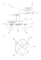
図1ないし図4に本発明の実施の形態を示す。この実施の形態において、測量用標識9は、図1に示すように、標識部1を搭載し、無線により遠隔操作可能な小型の模型自動車21と、この模型自動車21への操作を無線遠隔入力するための遠隔操作装置22とを有する。
1 to 4 show an embodiment of the present invention. In this embodiment, as shown in FIG. 1, the surveying
上記模型自動車21は、走行駆動装置23を備え、該走行駆動装置23の駆動部23aにより車輪24に動力を与えて自走し、また、この駆動部23aを作動させるために図外のバッテリ等の給電手段を搭載する。また、上記走行駆動装置23は、駆動部23aを制御する駆動制御部23bを有し、この駆動制御部23bは、受信部25を介して上記遠隔操作装置22からの操作信号が入力されると、操作信号に従って駆動部23aを制御する。なお、図1において26はアンテナである。
The
上記遠隔操作装置22は、オペレータからの操作が入力される操作入力部27を有し、操作内容に応じた操作信号を送信部29を通じてアンテナ30から出力する。この遠隔操作装置22も上述の模型自動車21同様、図外の給電手段を備える。なお、以上の模型自動車21と遠隔操作装置22は、ラジオコントロール可能な玩具として市販されているものを活用して構成することができる。
The
一方、上記標識部1は、図1(b)に示すように、立方体近似のボックス状に形成され、模型自動車21に取り付けられる下面側を除く外表面5面を標識面3とする多面標識体4を有する。各標識面3は、その中心位置の把握を容易にする照準近似の模様5を施され、また、レーザ光等の測距用光波を再帰反射可能に形成される。上記模様5は、具体的には、正方形からなる各標識面3にその図心位置を中心とし、直径が標識面3の一辺よりもやや長い円形近似の図形を描き、この図形の外側の領域を灰色に着色するとともに、この図形の内側の領域を四分円毎に市松模様のように白黒の色違いに着色して構成される。以上の多面標識体4は、例えば合成樹脂材などの軽量の素材を中空のボックス状にして形成することが可能であり、また、その模様5は、例えば、各標識面3に測距用光波を再帰反射する白、黒、および灰色の粘着シートを張り付けるなどして形成することが可能である。
On the other hand, as shown in FIG. 1 (b), the marking
以上の多面標識体4は、ジンバル機構2より支持され、このジンバル機構2を介して模型自動車21に取り付けられる。上記ジンバル機構2は、多面標識体4の5面の標識面3、3、・・を水平姿勢や鉛直姿勢に保持するもので、具体的には例えば、多面標識体4のピッチ方向およびロール方向の回転をジャイロで検出し、この回転を打ち消すように多面標識体4をモータで回転駆動させることにより、各標識面3が水平姿勢や鉛直姿勢を維持するように多面標識体4の姿勢を制御する。また、上記ジンバル機構2には、その姿勢維持機能を停止可能な図示省略のストッパも組み込まれており、該ストッパを模型自動車21の走行時に作動させることにより、移動時の振動から保護等される。このストッパは、上述した遠隔操作装置22により遠隔で作動あるいは解除することができる。
The
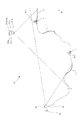
以上の測量用標識9は、この実施の形態においては、斜面崩壊の発生現場(斜面崩壊や地すべりなどの発生現場13)の地形を測量する際に使用される。この測量は、図2に示すように、崩壊斜面を中心とした所定の地理範囲内を対象とし、地上測量と空中測量を併用してなされる。
In the present embodiment, the above-described
上記地上測量は、レーザ測量であり、斜面崩壊の発生現場13からある程度離れていて仮に二次崩壊が発生した場合にも安全性を確保でき、かつ、崩壊斜面を含めて周囲の見通しが良い場所にレーザ測距装置30を設置してなされる。このレーザ測距装置30の設置地点は、図外の地上基準点からの三角測量などにより既知点8にされる。
The above-mentioned ground survey is a laser survey, and it is possible to secure safety even if a secondary collapse occurs if it is some distance away from the slope
一方、空中測量は、写真測量であり、無線により遠隔操作可能な小型の模型ヘリコプター31に撮影装置31dを搭載させてなされる。この模型ヘリコプター31は、回転翼31aを駆動、制御する飛行駆動装置31bに加えて、GNSS(Global Navigation Satellite System)受信機31cや、上記撮影装置31dを支持し、その撮影方向を直下に保持するジンバル機構31eをも有しており、これにより写真測量の外部標定要素が特定される。
On the other hand, the aerial survey is a photogrammetry and is performed by mounting a photographing device 31d on a
測量に際しては、前準備として先ず最初に、図2に示すように、崩壊斜面の頂部近傍や裾野近傍などの測量対象範囲内であって、レーザ測距装置30の設置場所からの視通および上空視通がとれる位置に測量用標識9の適数が設置される。この設置は、オペレータが遠隔操作装置22を操作して測量用標識9の模型自動車21を無線遠隔操作により移動制御してなされ、また、設置状態において標識部1の標識面3は、ジンバル機構2により鉛直姿勢や水平姿勢に保持される。
When preparing for surveying, first of all, as shown in FIG. 2, as shown in FIG. 2, it is within the survey target range such as the vicinity of the top of the collapsed slope and the vicinity of the bottom, and the view from the installation location of the laser
次いで、レーザ測距装置30を作動させて測量対象範囲の地形を地上からレーザ計測し、また、模型ヘリコプター31を遠隔操作装置22により遠隔操作し、例えば対地高度数百メートルの上空から測量対象範囲の地形をステレオ撮影、すなわち異なる方向から重複して撮影すれば、現場での測量作業は終了する。なお、図2において一点鎖線はレーザ測距装置30等bによる測量範囲を示したもの、矢印は重力方向Gを示したものであり、また、上述の空中写真測量における撮影縮尺は1/500以上に確保される。
Next, the
また、以上のようにして現場で得られた地上測量と空中測量のそれぞれの成果は、この後、統合処理装置32により統合される。この統合処理装置32は、具体的にはコンピュータであり、図3に示すように、地上測量と空中測量のそれぞれの測量成果である地上測量データ33と空中測量データ34が入力される入力部35と、これら地上測量データ33と空中測量データ34を統合処理する演算部36と、統合処理結果等を図外のディスプレイなどに出力する出力部37とを有する。 Further, the results of the ground survey and the aerial survey obtained at the site as described above are integrated by the integrated processing device 32 thereafter. The integrated processing device 32 is specifically a computer, and as shown in FIG. 3, an input unit 35 to which ground survey data 33 and aerial survey data 34, which are the survey results of the ground survey and the aerial survey, are input. And a calculation unit 36 that integrates the ground survey data 33 and the aerial survey data 34, and an output unit 37 that outputs a result of the integration process to a display (not shown).
上記入力部35には、地上測量の成果としてレーザ測距データ33aが入力されるとともに、レーザ測距装置30の設置地点(既知点8)の3次元座標値などのようにレーザ測距データ33aを標定するのに必要なデータが地上標定データ33bとして入力される。また、空中測量の成果として空中写真データ34aが入力されるとともに、GNSS受信機31cにより得られた撮影地点の3次元座標値などのように空中写真データ34aを標定するのに必要なデータが空中標定データ34bとして入力される。なお、上述のようにステレオ撮影がされるために、空中写真データ34aはステレオペア画像で構成される。
Laser ranging data 33a is input to the input unit 35 as a result of ground surveying, and laser ranging data 33a such as a three-dimensional coordinate value of an installation point (known point 8) of the
また、上記演算部36は、図3に示すように、上述の地上測量データ33や空中測量データ34の各々に基づいて、相互に比較可能な比較用データの各々を生成する地上正射データ生成部38や空中正射データ生成部39と、測量対象範囲内において地上測量では計測できない領域、言い換えればレーザ測距装置30の設置位置から照射した測距用レーザ光が途中で遮られるなどして届かない、測量データのデータ欠損領域11を抽出する欠損領域抽出部40と、上記比較用データに基づいて地上測量データ33と空中測量データ34のそれぞれの測量要素をマッチングをするマッチング処理部41と、これらの測量要素を統合する統合部43とを有する。
Further, as shown in FIG. 3, the calculation unit 36 generates ground orthographic data that generates comparison data that can be compared with each other based on the above-described ground survey data 33 and aerial survey data 34. The laser beam for distance measurement irradiated from the position where the laser
上記地上正射データ生成部38は、図3に示すように、地上測量データ33、すなわち点群データ(地上測量点群データ)から測量用標識9の位置を抽出する標識抽出部38aと、上記地上測量点群データから3次元形状モデルを生成する3次元形状モデル生成部38bと、上記地上測量点群データを地表面に対する正射影位置に配列した地上測量正射データを生成する正射データ生成部38cとを有する。上記標識抽出部38aは、標識面3で測距用レーザ光が反射するのを利用してその位置を抽出するものであり、例えば3次元座標値をもつ個々の点の集まりである地上測量点群データ内において、既知である標識面3の広さに応じたサイズの垂直面を検索し、当該垂直面を標識面3として抽出する。この標識抽出部38aは、この実施の形態においては上述のようにサイズとその垂直姿勢を条件に地上測量点群データから標識面3を自動抽出するが、マウス等の入力手段を通じたオペレータからの指定に従って抽出しても足りる。
As shown in FIG. 3, the ground orthographic data generation unit 38 includes a
上記3次元形状モデル生成部38bは、地上測量データ33の地上測量点群データが示す3次元座標値に従ってTIN(Triangulated Irregular Network)等により構成されるDSM(Digital Surface Model)を生成する。
The three-dimensional shape
上記正射データ生成部38cは、地上測量点群データを上記DSMに投影し、地上測量点群データを構成する各点を正射影位置に位置変換、位置調整した地上測量正射データを生成する。
The orthographic
一方、空中正射データ生成部39は、図3に示すように、空中測量データ34、すなわちステレオペア画像から測量用標識9の位置を抽出する標識抽出部39aと、上記ステレオペア画像から3次元形状モデルを生成する3次元形状モデル生成部39bと、上記ステレオペア画像から点群データ(空中測量点群データ)を生成する点群データ生成部39cと、上記空中測量点群データを地表面に対する正射影位置に配列した空中測量正射データを生成する正射データ生成部39dとを有する。上記標識抽出部39aは、写真画像に写る標識面3を抽出するものであり、例えば既知である標識面3の広さに応じたサイズや模様5、色を頼りに標識面3を特定し、抽出する。なお、標識抽出部39aは、上述した地上正射データ生成部38の標識抽出部38aと同様に、標識面3を自動抽出する以外に、マウス等の入力手段を通じたオペレータからの指定に従って抽出しても足りる。
On the other hand, as shown in FIG. 3, the aerial orthogonal data generation unit 39 includes the aerial survey data 34, that is, the
上記3次元形状モデル生成部39bは、空中測量データ34を利用して、写真測量の要領に従ってステレオマッチングによりDSMを生成する。また、上記点群データ生成部39cは、市販の点群データ生成ソフト同様、上記DSMを利用してステレオペア画像から点群データ(空中測量点群データ)を生成する。
The three-dimensional shape
さらに、上記正射データ生成部39dは、上述した地上正射データ生成部38における正射データ生成部38cと同様に、上記空中測量点群データを上述のDSMに投影し、空中測量点群データの各点を正射影位置に位置変換、位置調整した空中測量正射データを生成する。
Further, the orthographic
一方、欠損領域抽出部40は、上述した地上測量正射データにおける点群の配置の多寡に基づき、点の存在しない領域をデータ欠損領域11として自動抽出する。具体的には、図2に太線で示すように、崩壊斜面の頂部や、裾野の凹部には、地上測量の測距用レーザ光が届かない領域が発生しており、これに応じて地上測量正射データにも、図4において実線で囲まれたデータ欠損領域11が発生する。なお、図2において崩壊斜面の中腹に位置する太線は、空中測量において計測できない、すなわち写真撮影できない領域を示すものであり、また、図4(a)においてデータ欠損領域11内等に二点鎖線で矩形近似に示された図形は、標識部1の標識面3を参考に示したものである。また、図4(a)および後述する図4(b)において多数の小さな丸印は点群データを構成する各々の点を模式的に示したものである。なお、欠損領域抽出部40は、データ欠損領域11を地上測量正射データから自動抽出する以外に、マウス等の入力手段を通じたオペレータからの指定に従って抽出しても足りる。
On the other hand, the missing
また、上記マッチング処理部41は、地上測量正射データと空中測量正射データがマッチングする相対位置関係を判定する。具体的には、上述した各標識抽出部38a、39aにより抽出された標識面3の位置を材料として相対位置関係を決定する。なお、マッチングに際しては、地上正射データ生成部38の標識抽出部38aにおいて得られた標識部1の鉛直姿勢の標識面3の位置に基づいて、地上測量正射データにおける標識部1の水平姿勢の標識面3の対応位置が計算され、この対応位置の標識面3と、空中正射データ生成部39の標識抽出部39aにおいて得られた水平姿勢の標識面3の空中測量正射データにおける位置とがマッチングされる。また、マッチングに際しては標識面3の中心位置が求められ、この中心位置に基づいて地上測量正射データと空中測量正射データの相対位置関係が判定される。なお、マッチングの際に地上測量正射データと空中測量正射データと間の計測誤差の調整値、変換パラメータを算出しておけば、地上測量において精度の高い標高値と、空中測量において精度の高い平面座標値の双方の精度を有効に活用したマッチング条件を得ることも可能である。
The matching processing unit 41 determines a relative positional relationship in which the ground survey orthographic data and the aerial survey orthographic data match. Specifically, the relative positional relationship is determined using the position of the
さらに、上記統合部43は、以上のマッチング処理部41によるマッチング成果に基づき、上述の欠損領域抽出部40により抽出された地上測量正射データのデータ欠損領域11に、空中測量正射データにおける対応データ領域12のデータを組み込み、地上測量と空中測量の双方の成果を統合した点群データを生成し、また、この点群データに基づいて測量対象範囲の地形の3次元形状データを生成する。図4(b)は、空中測量正射データを示すものであり、二点鎖線で囲まれた領域が対応データ領域12である。また、図4(a)と同図(b)とを比較すると明らかなように、地上測量正射データと空中測量正射データとは、地上分解能が異なるために、上述したマッチング処理や統合処理に際しては分解能が合致するように縮尺等が調整される。
Further, the
以上のようにして統合部43により生成された3次元形状データ、すなわちDSMは、図2に太線で示す全てのデータ欠損領域11が解消されたものになり、これが出力部37を介して図外のディスプレイに出力される。
As described above, the three-dimensional shape data generated by the
また、以上において述べたような測量作業や、この測量作業により得られた測量成果に基づく統合処理装置32による3次元形状データの生成処理は、一定期間毎に繰り返され、得られた3次元形状データ同士を比較することにより、二次崩壊の発生状況を含む斜面崩壊の時系列変化が解析される。なお、上記比較は、ディスプレイに表示された3次元形状データ同士をオペレータがそれぞれ目視してすることが可能であるが、3次元形状データ同士の一致、不一致を比較演算処理により検出する比較部を演算部36に設ければ、より簡単かつ高精度にすることができる。 Further, the three-dimensional shape data generation processing by the integrated processing device 32 based on the surveying work described above and the survey result obtained by the surveying work is repeated at regular intervals, and the obtained three-dimensional shape is obtained. By comparing the data, the time series change of slope failure including the occurrence of secondary failure is analyzed. In the above comparison, the operator can visually check each of the three-dimensional shape data displayed on the display. However, a comparison unit that detects a match or mismatch between the three-dimensional shape data by a comparison calculation process is provided. If it is provided in the calculation unit 36, it can be made simpler and more accurate.
なお、以上においては地上測量のデータ欠損領域11を空中測量の対応データ領域12で穴埋めする場合を示したが、反対に、空中測量のデータ欠損領域11を地上測量の対応データ領域12で穴埋めしても足り、この場合には例えば、地上測量点群データと空中測量点群データの双方を正射影方向に直交する方向に配置調整してからマッチング等すれば足りる。また、ジンバル機構2はピッチ方向とロール方向のみの2軸ではなく、ヨー方向への測量用標識9の回転をも打ち消す3軸対応のものを用いることも可能であり、この場合には、鉛直姿勢の標識面3を地上の計測地点、すなわちレーザ測距装置30の設置位置向かって正対、あるいは正対近似に保持することにより位置精度の向上を図ることができる。
In the above, the case where the
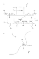
図5に測量用標識9の他の実施の形態を示す。なお、以下に述べるこの実施の形態を含む全ての実施の形態の説明において、上述した実施の形態と同一の要素は同一の符号を付して説明を省略する。この実施の形態において、測量用標識9の標識部1は、図5(a)に示すように、無線により遠隔操作可能な小型の模型ヘリコプター43に搭載される。
FIG. 5 shows another embodiment of the surveying
上記模型ヘリコプター43は、飛行駆動装置44の駆動部44aにより回転翼43aに動力を与え、これにより生じる揚力により自力飛行し、また、図外のバッテリ等の給電手段を搭載する。また、飛行駆動装置44の駆動制御部44bは、受信部45を介して図外の遠隔動作装置22からの操作信号が入力されると、操作信号に従って駆動部44aを制御する。なお、図1において46はアンテナである。以上の模型ヘリコプター31も、ラジオコントロール可能な玩具として市販されているものを活用して構成することができる。なお、図5(a)において43bは、着陸時に地面に接する脚部である。
The
したがってこの実施の形態においては、図5(b)に示すように、崩壊斜面の中腹に生じた岩棚47など、上述の模型自動車21の走行によっては到達が困難な場所にも標識部1を簡単に配置することができる。
Therefore, in this embodiment, as shown in FIG. 5 (b), the
図6にさらに他の測量用標識9を用いてなされる測量の他の実施の形態を示す。この実施の形態において、標識部1は、上述した多面標識体4に代えて、測距用光波を再帰反射するプリズムミラー6により構成され、測量用標識9は、上記プリズムミラー6をジンバル機構2を介して模型自動車21に取り付け、また、水平姿勢に保持して形成される。
FIG. 6 shows another embodiment of surveying performed using another
また、測量には、自動追尾機能を備えたトータルステーション48が用いられる。図6に二点鎖線の矢印で示すように、遠隔操作装置22により測量用標識9を順次適数の求点7上に移動させ、自動追尾機能を利用してトータルステーション48により各求点7上にある測量用標識9の位置を測量させる、すなわち具体的には、各求点7上で測量用標識9を停止させた状態で測量命令をトータルステーション48に入力すれば、図6において一点鎖線の矢印で示すように自動で視準、測距、測角し、また記録処理がなされるために、極めて迅速、かつ簡単に測量作業が終了する。なお、図6において48aは三脚である。
For the surveying, a
1 標識部
2 ジンバル機構
3 標識面
4 多面標識体
5 模様
6 プリズムミラー
7 求点
8 既知点
9 測量用標識
10 測量対象領域
11 データ欠損領域
12 対応データ領域
13 斜面崩壊や地すべりなどの発生現場
G 重力方向
DESCRIPTION OF
Claims (10)
前記計測に先立って、測量用標識を遠隔操作により既知点からの視通がとれる位置に設定した求点上まで自走あるいは自力飛行させるとともに、前記測量用標識の標識部をジンバル機構により鉛直姿勢に保持させる測量方法。 A surveying method for measuring the ground coordinates of a sought point from known points on the ground,
Prior to the measurement, the surveying sign is self-propelled or self-flighted on a point set at a position where it can be seen from a known point by remote control, and the signage part of the surveying sign is vertically positioned by a gimbal mechanism. Surveying method to be held.
前記空中計測に先立って、測量用標識を遠隔操作により上空視通がとれる位置に設定した求点上まで自走あるいは自力飛行させるとともに、前記測量用標識の標識部をジンバル機構により鉛直姿勢に保持させる測量方法。 A surveying method that measures the ground coordinates of a sought point from the sky,
Prior to the aerial measurement, the surveying sign is self-propelled or flies to a point set at a position where the aerial view can be taken remotely, and the sign part of the surveying sign is held in a vertical posture by a gimbal mechanism. Survey method to make.
直交する複数の標識面を備えてボックス状に形成された多面標識体を有する測量用標識を測量対象領域内において地上の既知点からの視通および上空視通がとれる位置に配置するとともに、該測量用標識に形成されたジンバル機構により前記複数の標識面を水平姿勢および鉛直姿勢に保持させ、
次いで、前記既知点からの地上測量により3次元位置を各点において特定可能で、かつ鉛直姿勢の標識面を判別可能な測量対象領域の地上測量点群データを取得するとともに、上空からの空中測量によって3次元位置を各点において特定可能で、かつ水平姿勢の標識面を判別可能な測量対象領域の空中測量点群データを取得し、
この後、いずれか一方の点群データに基づいて測量対象領域の3次元形状モデルを形成する際のデータ欠損領域についての他方の点群データにおける対応データ領域を各点群データにおける標識面の3次元位置を利用して特定し、対応データ領域によりデータ欠損領域を補完して3次元形状モデルを形成する測量方法。 A surveying method that generates map information by integrating the survey results of both ground surveys and aerial surveys,
A surveying marker having a multi-surface marker formed in a box shape with a plurality of orthogonal marker surfaces is arranged in a survey target area at a position where a view from a known point on the ground and an aerial view can be taken, By holding the plurality of marking surfaces in a horizontal posture and a vertical posture by a gimbal mechanism formed on the surveying sign,
Next, the ground survey point area data of the survey target area which can identify the three-dimensional position at each point by the ground survey from the known point and can discriminate the sign surface of the vertical posture is obtained, and the aerial survey from the sky To obtain the aerial survey point cloud data of the survey target area where the three-dimensional position can be identified at each point and the sign surface of the horizontal posture can be identified,
Thereafter, the corresponding data area in the other point cloud data with respect to the data missing area when the three-dimensional shape model of the survey target area is formed based on any one of the point cloud data is set to 3 on the sign plane in each point cloud data. A surveying method in which a three-dimensional shape model is formed by specifying a three-dimensional position and complementing a data missing region with a corresponding data region.
Priority Applications (1)
| Application Number | Priority Date | Filing Date | Title |
|---|---|---|---|
| JP2014142931A JP6290735B2 (en) | 2014-07-11 | 2014-07-11 | Survey method |
Applications Claiming Priority (1)
| Application Number | Priority Date | Filing Date | Title |
|---|---|---|---|
| JP2014142931A JP6290735B2 (en) | 2014-07-11 | 2014-07-11 | Survey method |
Publications (2)
| Publication Number | Publication Date |
|---|---|
| JP2016017931A true JP2016017931A (en) | 2016-02-01 |
| JP6290735B2 JP6290735B2 (en) | 2018-03-07 |
Family
ID=55233232
Family Applications (1)
| Application Number | Title | Priority Date | Filing Date |
|---|---|---|---|
| JP2014142931A Active JP6290735B2 (en) | 2014-07-11 | 2014-07-11 | Survey method |
Country Status (1)
| Country | Link |
|---|---|
| JP (1) | JP6290735B2 (en) |
Cited By (12)
| Publication number | Priority date | Publication date | Assignee | Title |
|---|---|---|---|---|
| WO2017119517A1 (en) * | 2017-01-13 | 2017-07-13 | 株式会社小松製作所 | Working-machine control system, working machine, and working-machine control method |
| JP2018048509A (en) * | 2016-09-23 | 2018-03-29 | 清水建設株式会社 | Management method and management device for tunnel excavation |
| JP2019020371A (en) * | 2017-07-11 | 2019-02-07 | 宏介 津留 | Aircraft indicator for orientation and calibration of aircraft-mounted camera and laser range finder |
| JP2019056562A (en) * | 2017-09-19 | 2019-04-11 | 株式会社トプコン | Control apparatus, unmanned aircraft, control processing method, and control processing program |
| JP2019060641A (en) * | 2017-09-25 | 2019-04-18 | 和樹 ▲柳▼ | Aerial marking, analysis device, and drone airborne survey system |
| JP2019138842A (en) * | 2018-02-14 | 2019-08-22 | 株式会社トプコン | Installation base for unmanned aerial vehicle, surveying method, surveying device, surveying system, and program |
| CN110186432A (en) * | 2019-07-08 | 2019-08-30 | 中国电建集团成都勘测设计研究院有限公司 | Ground control point installation aiding device for earth's surface deformation evolution |
| WO2019188961A1 (en) * | 2018-03-26 | 2019-10-03 | 株式会社トプコン | Target device and surveying system |
| JP2021085770A (en) * | 2019-11-28 | 2021-06-03 | 東亜道路工業株式会社 | Method, system and computer program for acquiring position information of mobile body |
| JP7201863B1 (en) | 2022-06-28 | 2023-01-10 | クモノスコーポレーション株式会社 | Measuring device and measuring method |
| CN115950305A (en) * | 2023-03-14 | 2023-04-11 | 四川省自然资源科学研究院(四川省生产力促进中心) | Unmanned aerial vehicle multifunctional ground phase control target device |
| WO2024004722A1 (en) * | 2022-06-28 | 2024-01-04 | 京セラ株式会社 | Electronic apparatus, control method, and control program |
Citations (9)
| Publication number | Priority date | Publication date | Assignee | Title |
|---|---|---|---|---|
| JP2002328021A (en) * | 2001-04-27 | 2002-11-15 | Hayashi Katsuyoshi | Method for measuring damage of disaster using helicopter photographing |
| JP2006003104A (en) * | 2004-06-15 | 2006-01-05 | Topcon Corp | Survey work guidance device |
| JP2007501945A (en) * | 2003-06-11 | 2007-02-01 | ハネウェル・インターナショナル・インコーポレーテッド | System and method for target location |
| JP2010540796A (en) * | 2007-04-09 | 2010-12-24 | サム・スタシス | System and method capable of navigating and / or mapping multidimensional space |
| JP2012122800A (en) * | 2010-12-07 | 2012-06-28 | Hitachi Plant Technologies Ltd | Measuring target |
| JP2012220333A (en) * | 2011-04-08 | 2012-11-12 | Topcon Corp | Surveying pole |
| JP2013171455A (en) * | 2012-02-21 | 2013-09-02 | Pasuko:Kk | Map information generating device |
| JP2014089211A (en) * | 2014-01-14 | 2014-05-15 | Sooki Co Ltd | Tunnel cross-section measurement method using three-dimensional laser scanner |
| US20140163775A1 (en) * | 2011-04-14 | 2014-06-12 | Hexagon Technology Center Gmbh | Geodetic marking system for marking target points |
-
2014
- 2014-07-11 JP JP2014142931A patent/JP6290735B2/en active Active
Patent Citations (9)
| Publication number | Priority date | Publication date | Assignee | Title |
|---|---|---|---|---|
| JP2002328021A (en) * | 2001-04-27 | 2002-11-15 | Hayashi Katsuyoshi | Method for measuring damage of disaster using helicopter photographing |
| JP2007501945A (en) * | 2003-06-11 | 2007-02-01 | ハネウェル・インターナショナル・インコーポレーテッド | System and method for target location |
| JP2006003104A (en) * | 2004-06-15 | 2006-01-05 | Topcon Corp | Survey work guidance device |
| JP2010540796A (en) * | 2007-04-09 | 2010-12-24 | サム・スタシス | System and method capable of navigating and / or mapping multidimensional space |
| JP2012122800A (en) * | 2010-12-07 | 2012-06-28 | Hitachi Plant Technologies Ltd | Measuring target |
| JP2012220333A (en) * | 2011-04-08 | 2012-11-12 | Topcon Corp | Surveying pole |
| US20140163775A1 (en) * | 2011-04-14 | 2014-06-12 | Hexagon Technology Center Gmbh | Geodetic marking system for marking target points |
| JP2013171455A (en) * | 2012-02-21 | 2013-09-02 | Pasuko:Kk | Map information generating device |
| JP2014089211A (en) * | 2014-01-14 | 2014-05-15 | Sooki Co Ltd | Tunnel cross-section measurement method using three-dimensional laser scanner |
Cited By (23)
| Publication number | Priority date | Publication date | Assignee | Title |
|---|---|---|---|---|
| JP2018048509A (en) * | 2016-09-23 | 2018-03-29 | 清水建設株式会社 | Management method and management device for tunnel excavation |
| US10774505B2 (en) | 2017-01-13 | 2020-09-15 | Komatsu Ltd. | Work machine control system, work machine, and work machine control method |
| JPWO2017119517A1 (en) * | 2017-01-13 | 2018-01-11 | 株式会社小松製作所 | Work machine control system, work machine, work machine control method, and navigation controller |
| WO2017119517A1 (en) * | 2017-01-13 | 2017-07-13 | 株式会社小松製作所 | Working-machine control system, working machine, and working-machine control method |
| JP2019020371A (en) * | 2017-07-11 | 2019-02-07 | 宏介 津留 | Aircraft indicator for orientation and calibration of aircraft-mounted camera and laser range finder |
| JP2019056562A (en) * | 2017-09-19 | 2019-04-11 | 株式会社トプコン | Control apparatus, unmanned aircraft, control processing method, and control processing program |
| JP7025157B2 (en) | 2017-09-19 | 2022-02-24 | 株式会社トプコン | Shooting method and shooting program |
| JP2019060641A (en) * | 2017-09-25 | 2019-04-18 | 和樹 ▲柳▼ | Aerial marking, analysis device, and drone airborne survey system |
| US11221216B2 (en) | 2018-02-14 | 2022-01-11 | Topcon Corporation | Placement table for unmanned aerial vehicle, surveying method, surveying device, surveying system and program |
| WO2019160022A1 (en) * | 2018-02-14 | 2019-08-22 | 株式会社トプコン | Installation stand of unmanned aircraft, measurement method, measurement device, measurement system and program |
| JP7043283B2 (en) | 2018-02-14 | 2022-03-29 | 株式会社トプコン | Unmanned aerial vehicle installation platform, surveying methods, surveying equipment, surveying systems and programs |
| JP2019138842A (en) * | 2018-02-14 | 2019-08-22 | 株式会社トプコン | Installation base for unmanned aerial vehicle, surveying method, surveying device, surveying system, and program |
| CN112005077A (en) * | 2018-02-14 | 2020-11-27 | 株式会社拓普康 | Setting table, measurement method, measurement device, measurement system, and program for unmanned aerial vehicle |
| EP3754298A4 (en) * | 2018-02-14 | 2021-11-17 | Topcon Corporation | Placement table for unmanned aerial vehicle, surveying method, surveying device, surveying system and program |
| WO2019188961A1 (en) * | 2018-03-26 | 2019-10-03 | 株式会社トプコン | Target device and surveying system |
| JP2019168406A (en) * | 2018-03-26 | 2019-10-03 | 株式会社トプコン | Target device and surveying system |
| JP7161298B2 (en) | 2018-03-26 | 2022-10-26 | 株式会社トプコン | target device, surveying system |
| CN110186432A (en) * | 2019-07-08 | 2019-08-30 | 中国电建集团成都勘测设计研究院有限公司 | Ground control point installation aiding device for earth's surface deformation evolution |
| JP2021085770A (en) * | 2019-11-28 | 2021-06-03 | 東亜道路工業株式会社 | Method, system and computer program for acquiring position information of mobile body |
| JP7201863B1 (en) | 2022-06-28 | 2023-01-10 | クモノスコーポレーション株式会社 | Measuring device and measuring method |
| WO2024004722A1 (en) * | 2022-06-28 | 2024-01-04 | 京セラ株式会社 | Electronic apparatus, control method, and control program |
| JP2024004339A (en) * | 2022-06-28 | 2024-01-16 | クモノスコーポレーション株式会社 | Measurement device and measurement method |
| CN115950305A (en) * | 2023-03-14 | 2023-04-11 | 四川省自然资源科学研究院(四川省生产力促进中心) | Unmanned aerial vehicle multifunctional ground phase control target device |
Also Published As
| Publication number | Publication date |
|---|---|
| JP6290735B2 (en) | 2018-03-07 |
Similar Documents
| Publication | Publication Date | Title |
|---|---|---|
| JP6290735B2 (en) | Survey method | |
| Vallet et al. | Photogrammetric performance of an ultra light weight swinglet UAV | |
| EP2902744B1 (en) | Measuring system | |
| JP6390013B2 (en) | Control method for small unmanned aerial vehicles | |
| EP2772725B1 (en) | Aerial Photographing System | |
| KR20200031165A (en) | Navigation chart configuration method, obstacle avoidance method and device, terminal, drone | |
| Kim et al. | Feasibility of employing a smartphone as the payload in a photogrammetric UAV system | |
| CN108090957B (en) | BIM-based terrain mapping method | |
| CN102591353A (en) | Flight control system for flying object | |
| ES2366717B1 (en) | INFORMATION COLLECTION EQUIPMENT IN WORKS AND INFRASTRUCTURES BASED ON AN UNTRIPULATED AIR VEHICLE. | |
| CN109911188A (en) | The bridge machinery UAV system of non-satellite navigator fix environment | |
| EP2224263B1 (en) | Automated landing zone site surveying | |
| JP6138326B1 (en) | MOBILE BODY, MOBILE BODY CONTROL METHOD, PROGRAM FOR CONTROLLING MOBILE BODY, CONTROL SYSTEM, AND INFORMATION PROCESSING DEVICE | |
| CN102023003A (en) | Unmanned helicopter three-dimensional positioning and mapping method based on laser detection and image recognition | |
| WO2021020569A1 (en) | Method for performing forest mensuration, forest mensuration system, method for determining flight path of unmanned aerial vehicle, image capturing method, dispersion method, and computer program | |
| EP3093616A1 (en) | Device and method for designating characteristic points | |
| JP2023041675A (en) | Drone-work support system and drone-work support method | |
| Yastikli et al. | The processing of image data collected by light UAV systems for GIS data capture and updating | |
| Davidson et al. | Airborne to UAS LiDAR: An analysis of UAS LiDAR ground control targets | |
| CN110945510A (en) | Method for spatial measurement by means of a measuring vehicle | |
| Siebert et al. | Mobile 3D mapping for surveying earthwork using an unmanned aerial vehicle (UAV) | |
| CN112146627B (en) | Aircraft imaging system using projection patterns on featureless surfaces | |
| Hlotov et al. | Accuracy investigation of creating orthophotomaps based on images obtained by applying Trimble-UX5 UAV | |
| JP2020071580A (en) | Information processing apparatus, flight control method and flight control system | |
| JP2023093808A (en) | Flight route normalization system, flight route normalization method, and flight route normalization program |
Legal Events
| Date | Code | Title | Description |
|---|---|---|---|
| A621 | Written request for application examination |
Free format text: JAPANESE INTERMEDIATE CODE: A621 Effective date: 20161021 |
|
| A977 | Report on retrieval |
Free format text: JAPANESE INTERMEDIATE CODE: A971007 Effective date: 20170816 |
|
| A131 | Notification of reasons for refusal |
Free format text: JAPANESE INTERMEDIATE CODE: A131 Effective date: 20170829 |
|
| A521 | Request for written amendment filed |
Free format text: JAPANESE INTERMEDIATE CODE: A523 Effective date: 20171030 |
|
| TRDD | Decision of grant or rejection written | ||
| A01 | Written decision to grant a patent or to grant a registration (utility model) |
Free format text: JAPANESE INTERMEDIATE CODE: A01 Effective date: 20180206 |
|
| A61 | First payment of annual fees (during grant procedure) |
Free format text: JAPANESE INTERMEDIATE CODE: A61 Effective date: 20180208 |
|
| R150 | Certificate of patent or registration of utility model |
Ref document number: 6290735 Country of ref document: JP Free format text: JAPANESE INTERMEDIATE CODE: R150 |
|
| S531 | Written request for registration of change of domicile |
Free format text: JAPANESE INTERMEDIATE CODE: R313531 |
|
| R350 | Written notification of registration of transfer |
Free format text: JAPANESE INTERMEDIATE CODE: R350 |
|
| R250 | Receipt of annual fees |
Free format text: JAPANESE INTERMEDIATE CODE: R250 |