JP2016011543A - Photovoltaic power generation roof and frame - Google Patents
Photovoltaic power generation roof and frame Download PDFInfo
- Publication number
- JP2016011543A JP2016011543A JP2014134185A JP2014134185A JP2016011543A JP 2016011543 A JP2016011543 A JP 2016011543A JP 2014134185 A JP2014134185 A JP 2014134185A JP 2014134185 A JP2014134185 A JP 2014134185A JP 2016011543 A JP2016011543 A JP 2016011543A
- Authority
- JP
- Japan
- Prior art keywords
- ridge
- roof
- power generation
- eaves
- vent
- Prior art date
- Legal status (The legal status is an assumption and is not a legal conclusion. Google has not performed a legal analysis and makes no representation as to the accuracy of the status listed.)
- Granted
Links
Images


Classifications
-
- Y—GENERAL TAGGING OF NEW TECHNOLOGICAL DEVELOPMENTS; GENERAL TAGGING OF CROSS-SECTIONAL TECHNOLOGIES SPANNING OVER SEVERAL SECTIONS OF THE IPC; TECHNICAL SUBJECTS COVERED BY FORMER USPC CROSS-REFERENCE ART COLLECTIONS [XRACs] AND DIGESTS
- Y02—TECHNOLOGIES OR APPLICATIONS FOR MITIGATION OR ADAPTATION AGAINST CLIMATE CHANGE
- Y02B—CLIMATE CHANGE MITIGATION TECHNOLOGIES RELATED TO BUILDINGS, e.g. HOUSING, HOUSE APPLIANCES OR RELATED END-USER APPLICATIONS
- Y02B10/00—Integration of renewable energy sources in buildings
- Y02B10/10—Photovoltaic [PV]
-
- Y—GENERAL TAGGING OF NEW TECHNOLOGICAL DEVELOPMENTS; GENERAL TAGGING OF CROSS-SECTIONAL TECHNOLOGIES SPANNING OVER SEVERAL SECTIONS OF THE IPC; TECHNICAL SUBJECTS COVERED BY FORMER USPC CROSS-REFERENCE ART COLLECTIONS [XRACs] AND DIGESTS
- Y02—TECHNOLOGIES OR APPLICATIONS FOR MITIGATION OR ADAPTATION AGAINST CLIMATE CHANGE
- Y02E—REDUCTION OF GREENHOUSE GAS [GHG] EMISSIONS, RELATED TO ENERGY GENERATION, TRANSMISSION OR DISTRIBUTION
- Y02E10/00—Energy generation through renewable energy sources
- Y02E10/50—Photovoltaic [PV] energy
Landscapes
- Roof Covering Using Slabs Or Stiff Sheets (AREA)
Abstract
Description
本発明は、太陽光発電屋根及び架台に関する。より詳しくは、本発明は、片流れ式の太陽光発電屋根及びそれに用いられる架台に関する。 The present invention relates to a photovoltaic roof and a mount. More specifically, the present invention relates to a single-flow solar roof and a gantry used therefor.
従来、建物の屋根と太陽光発電パネルとが一体に形成された、太陽光発電屋根が知られている(例えば、特許文献1参照)。太陽光発電パネルは、温度が上昇することで発電効率が低下してしまう。そこで、太陽光発電屋根においては、一般的に、太陽光発電パネルを建物の下地材から離隔して配置している。これにより、太陽光発電パネルと建物の下地材との間に通気路が形成され、その通気路に空気が流れることで、太陽光発電パネルの温度上昇が抑えられる。 Conventionally, a photovoltaic power generation roof in which a roof of a building and a photovoltaic power generation panel are integrally formed is known (see, for example, Patent Document 1). As for the solar power generation panel, the power generation efficiency decreases as the temperature rises. Therefore, in a photovoltaic roof, generally, a photovoltaic panel is arranged separately from a base material of a building. Thereby, an air passage is formed between the photovoltaic power generation panel and the base material of the building, and the air flows through the air passage, thereby suppressing the temperature rise of the photovoltaic power generation panel.
ところで、太陽光発電屋根ではないが、片流れ屋根の内部の換気のための構造として、軒側通気口とともに、棟側に配置された化粧材の上部に形成され軒側に開口した棟側通気口を有する通気路の形成された屋根が知られている(例えば、特許文献2参照)。
By the way, although it is not a solar power roof, as a structure for ventilation inside the single-flow roof, along with the eaves-side vents, the ridge-side vents that are formed in the upper part of the decorative material arranged on the wing side and open to the eaves side There is known a roof formed with a ventilation passage having, for example,
しかしながら、特許文献2に記載された、屋根の換気のための構造を、太陽光発電屋根に適用した場合、太陽光発電パネルの表面と棟化粧材の表面との間に段差が生じてしまい、外観の意匠性が悪化する。また、通気路の有する軒側通気口及び棟側通気口の両方が、軒側に向かって開口していることから、棟側から吹く風は通気路に吹き込まず、軒側から吹く風によって軒側通気口から通気路に吹き込んだ空気は棟側通気口において同じ軒側から吹く風によって押し返される。従って、このような構造の通気路の通気性は十分に満足できるものではない。
However, when the structure for ventilation of the roof described in
本発明は、通気路の通気性が十分に高い上に意匠性を高くすることが可能な太陽光発電屋根及びそれに用いられる架台を提供することを目的とする。 It is an object of the present invention to provide a photovoltaic power roof capable of sufficiently increasing the air permeability of the air passage and improving the design, and a mount used for the roof.
上記目的を達成するため本発明は、太陽光発電屋根(例えば、後述の太陽光発電屋根1)であって、棟から軒に亘って配置される架台(例えば、後述の太陽光パネル架台4)と、下地材(例えば、後述の下地材3)から離隔して配置されるとともに前記架台上に固定される太陽光発電パネル(例えば、後述の太陽光発電パネル5)と、を備え、前記架台は、前記下地材に固定される架台本体(例えば後述の架台本体40)と、前記架台本体の棟側の端部を覆うように配置される棟化粧材(例えば、後述の棟側枠材62)と、を備え、前記太陽光発電パネルと前記下地材との間には、軒側に開口する軒側通気口(例えば、後述の軒側通気口71)と、棟側に開口する棟側通気口(例えば、後述の棟側通気口72)と、を有する通気路(例えば、後述の通気路7)が形成され、前記棟化粧材は、前記棟側通気口を介して前記通気路に連通するとともに、前記棟を介して前記棟側通気口とは逆側に配置される排気口(例えば、後述の排気口81)を有する排気路(例えば、後述の排気路8)を形成する太陽光発電屋根を提供する。
In order to achieve the above object, the present invention is a solar power roof (for example, a solar power roof 1 described later), and a frame (for example, a
これにより、軒側から吹く風によって軒側通気口から通気路に吹き込んだ空気は、通気路及び排気路を経由して排気口から棟側に抜ける。逆に、棟側から吹く風によって排気口から排気路に吹き込んだ空気は、排気路及び通気路を経由して軒側通気口から軒側に抜ける。このように、太陽光発電屋根は、軒側通気口及び排気路が互いに逆方向に向いて開口していることから通気性が十分に高い。更に、太陽光発電屋根は、棟側の通気口が棟側枠材の上側に形成されていないことから、太陽光発電パネルの表面と棟側枠材の表面との間の段差を大きくする必要がないので、意匠性を高くすることが可能である。 Thereby, the air blown into the ventilation path from the eaves-side vent by the wind blown from the eaves side passes through the ventilation path and the exhaust path to the building side. On the contrary, the air blown into the exhaust passage from the exhaust port by the wind blown from the building side passes through the exhaust passage and the vent passage to the eave side from the eave side vent. Thus, the solar power roof has sufficiently high air permeability because the eaves-side vent and the exhaust passage are opened in opposite directions. Furthermore, since the roof on the photovoltaic power generation roof is not formed on the upper side of the ridge-side frame material, it is necessary to increase the level difference between the surface of the photovoltaic power generation panel and the surface of the ridge-side frame material. Therefore, it is possible to improve the design.
また、前記太陽光発電屋根は、片流れ式であり、前記排気路内における片流れ屋根の棟側の端部に立設され、前記通気路に連通する通気路側排気路(例えば、後述の通気路側排気路82S)と、前記排気口に連通する排気口側排気路(例えば、後述の排気口側排気路83S)と、これらを連通する連通路(例えば、後述の連通路84S)とに前記排気路を仕切る水返し材(例えば、後述の水返し材9S)を更に備えることが好ましい。
In addition, the solar power roof is a single-flow type, and is erected on the ridge-side end of the single-flow roof in the exhaust path, and communicates with the vent path (for example, a vent-path-side exhaust described later).
また、本発明は、下地材(例えば、後述の下地材3)から離隔して配置される太陽光発電パネル(例えば、後述の太陽光パネル架台4)を備える太陽光発電屋根(例えば、後述の太陽光発電パネル5)において、棟から軒に亘って配置されるとともに、前記太陽光発電パネルを固定する架台(例えば、後述の太陽光パネル架台4)であって、前記下地材に固定される架台本体(例えば後述の架台本体40)と、前記架台本体の棟側の端部を覆うように配置される棟化粧材(例えば、後述の棟側枠材62)と、を備え、前記架台本体は、前記太陽光発電パネルと前記下地材との間に、軒側に開口する軒側通気口(例えば、後述の軒側通気口71)と、棟側に開口する棟側通気口(例えば、後述の棟側通気口72)と、を有する通気路(例えば、後述の通気路7)を形成し、前記棟化粧材は、前記棟側通気口を介して前記通気路に連通するとともに、前記棟を介して前記棟側通気口とは逆側に配置される排気口(例えば、後述の排気口81)を有する排気路(例えば、後述の排気路8)を形成する架台を提供する。
In addition, the present invention provides a photovoltaic roof (for example, described later) provided with a photovoltaic panel (for example, a later-described solar panel mount 4) arranged separately from a foundation material (for example, a later-described foundation material 3). In the solar power generation panel 5), the solar
本発明によれば、通気路の通気性が十分に高い上に意匠性を高くすることが可能な太陽光発電屋根及びそれに用いられる架台を提供できる。 According to the present invention, it is possible to provide a photovoltaic power roof capable of sufficiently increasing the air permeability of the air passage and improving the design, and a mount used for the roof.
以下、本発明の実施形態について図面を参照しながら詳細に説明する。 Hereinafter, embodiments of the present invention will be described in detail with reference to the drawings.
まず、本発明の第1実施形態について説明する。
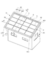
図1は、本発明の第1実施形態に係る太陽光発電屋根を示す斜視図である。図1に示すように、太陽光発電屋根1は、建物2の屋根と太陽光発電パネルとが一体形成されたものであり、統一感のある高い意匠性を有する。太陽光発電屋根1は、棟から片側に傾斜する屋根面を有する片流れ式の屋根であって、屋根面の略全面が太陽光発電パネルと一体形成されている。
First, a first embodiment of the present invention will be described.
FIG. 1 is a perspective view showing a photovoltaic power roof according to the first embodiment of the present invention. As shown in FIG. 1, the solar power roof 1 is formed by integrally forming the roof of the
以下、太陽光発電屋根1の構成について、図1〜4を参照して詳しく説明する。
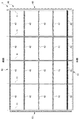
ここで、図2は、太陽光発電屋根1の屋根面1Aの下地材上に配置される太陽光パネル架台の平面図である。また、図3は、図1のA−A線断面図であり、図4は、図1のB−B線断面図である。
Hereinafter, the configuration of the solar power roof 1 will be described in detail with reference to FIGS.
Here, FIG. 2 is a plan view of the solar panel mount arranged on the base material of the
太陽光発電屋根1は、図1〜4に示すように、屋根面1Aに配置される、下地材3と、太陽光パネル架台4と、太陽光発電パネル5と、を備える。
As shown in FIGS. 1 to 4, the solar power generation roof 1 includes a
下地材3は、図3及び4に示すように、野地板31と、防水シート32と、鋼板33と、を備える。下地材3は、太陽光発電屋根1の土台部分を構成し、後述する太陽光パネル架台4を固定支持する。
As shown in FIGS. 3 and 4, the
野地板31は、建物2の屋根の骨組みである垂木30の上に張られて配置される。この野地板31は、太陽光発電屋根1の全面に配置される。野地板31としては、合板等の板材が用いられる。
The
防水シート32は、上述の野地板31上に配置される。この防水シート32により、太陽光発電屋根1の防水性が高められる。防水シート32としては、板紙にアスファルトを含浸させたアスファルトルーフィング等の防水材料が用いられる。
The
鋼板33は、上述の防水シート32上に配置される。この鋼板33により、太陽光発電屋根1の防火性、防水性及び強度が高められる。鋼板33としては、従来公知の防火鋼板等が用いられる。
The
太陽光パネル架台4は、棟から軒に亘って配置される。太陽光パネル架台4は、架台本体40と、化粧材6と、を備える。架台本体40は、図2〜4に示すように、上述の下地材3上にビス止めされて固定される。また、架台本体40は、上述の太陽光発電パネル5を固定支持する。化粧材6については、後段で詳述する。
架台本体40は、格子状に枠組みされた複数の縦桟41と、複数の横桟42と、を備える。
The
The
縦桟41は、屋根面1Aの傾斜方向に延びて、棟から軒先に亘って通しで設けられる。縦桟41は、屋根面1Aの傾斜方向に沿うようにして一定間隔で複数配置されて下地材3にビス止めされる。また、縦桟41は、後述の隣接する太陽光発電パネル5の縦辺部の継ぎ目51の直下に配置される。
The
横桟42は、屋根面1Aの傾斜方向に直交する方向に延びて設けられ、縦桟41上にビス止めされる。横桟42は、後述の隣接する太陽光発電パネル5の横辺部の連結部である横連結部52の直下に配置される。また、横桟42は、隣接する縦桟41同士を、あるいはケラバ側端部では後述のケラバ側枠材63と縦桟41との間を、橋渡しするように複数設けられる。即ち、横桟42は、両ケラバ側端部間に亘って通しで設けられてはいない。
The
なお、架台本体40を構成する縦桟41と横桟42は、それぞれ種々の排水構造を備える。
The
太陽光発電パネル5は、図1及び2に示すように、太陽光発電屋根1の屋根面1Aの傾斜方向に4枚、該傾斜方向と直交する方向に4枚の計16枚が並設され、上述の太陽光パネル架台4(架台本体40)上に固定支持される。太陽光発電パネル5は、下地材3から離隔して配置される。図4に示すように、太陽光発電パネル5と下地材3との間には、架台本体40によって通気路7が形成される。
太陽光発電パネル5の周縁部のうち、屋根面1Aの傾斜方向に沿う縦辺部は、隣接する太陽光発電パネル5の縦辺部との間に、縦方向に延びる継ぎ目51を形成する。
また、太陽光発電パネル5の周縁部のうち、屋根面1Aの傾斜方向に直交する方向に沿う横辺部は、上述の架台本体40を構成する横桟42を間に挟んで、隣接する太陽光発電パネル5の横辺部に連結されることで、横連結部52を形成する。
As shown in FIGS. 1 and 2, the photovoltaic
Of the peripheral edge portion of the photovoltaic
Moreover, the horizontal side part along the direction orthogonal to the inclination direction of 1 A of roof surfaces among the peripheral parts of the photovoltaic
横連結部52は、上述したように、架台本体40を構成する横桟42の直上に配置される。また、横連結部52には、隣接する太陽光発電パネル5の横辺部により挟持される横桟42の上部に、両横辺部に沿って延びるパネル押え部材521が取り付けられる。
As described above, the horizontal connecting
化粧材6は、図1及び2に示すように、軒側枠材61と、棟側枠材62と、一対のケラバ側枠材63,63と、を備える。これら軒側枠材61、棟側枠材62及び一対のケラバ側枠材63,63は、架台本体40(太陽光発電パネル5)の周囲を囲繞する周囲枠を構成する。
As shown in FIGS. 1 and 2, the decorative material 6 includes an eaves
軒側枠材61は、太陽光発電屋根1の軒先に配置される。軒側枠材61は、太陽光発電屋根1の屋根面1Aの傾斜方向に直交する方向に延びてその軒先を覆うことで、軒先を保護する。これにより、軒先の意匠性が高められている。
軒側枠材61は、図4に示すように、軒カバー611と、軒端部カバー612と、を備える。
The eaves
As shown in FIG. 4, the eaves
軒カバー611は、軒先に沿って延設され、上述の架台本体40を構成する横桟42にビス止めされる。また、軒カバー611は、断面視で、屋根面の傾斜方向に沿って延びた後、軒先に向かうに従い下方に傾斜して設けられる。
軒端部カバー612は、軒先の妻側の端部に設けられる。軒端部カバー612は、軒カバー611の外形に沿って軒カバー611を覆うように設けられ、軒カバー611にビス止めされる。
The eaves cover 611 extends along the eaves edge, and is screwed to the
The
棟化粧材としての棟側枠材62は、太陽光発電屋根1の架台本体40(縦桟41)の棟側の端部を覆うように配置される。棟側枠材62は、太陽光発電屋根1の屋根面1Aの傾斜方向に直交する方向に延びてその棟部を覆うことで、棟部を保護する。これにより、棟部の意匠性が高められている。棟側枠材62は、図4に示すように、棟カバー621と、棟アタッチメント622と、棟端部カバー623と、を備える。
The wing-
棟カバー621は、棟に沿って延設され、棟アタッチメント622にビス止めされる。また、棟カバー621は、断面視で、棟側に向かって屋根面の傾斜方向に沿って延びた後、下方に傾斜して設けられる。
棟アタッチメント622は、棟に沿って延設され、上述の架台本体40を構成する縦桟41にビス止めされる。
棟端部カバー623は、棟の妻側の端部に設けられる。棟端部カバー623は、棟カバー621の外形に沿って棟カバー621を覆うように設けられ、棟カバー621にビス止めされる。
The
The
The
一対のケラバ側枠材63,63は、太陽光発電屋根1のケラバ側の端部に配置される。一対のケラバ側枠材63,63は、太陽光発電屋根1の屋根面1Aの傾斜方向に延びて妻側の端部をそれぞれ覆うことで、妻側の端部を保護する。これにより、妻側の端部の意匠性が高められている。
図3に示すように、一対のケラバ側枠材63,63は、それぞれ第1ケラバ側枠材631と、第2ケラバ側枠材632を有する。
The pair of keraba
As shown in FIG. 3, the pair of keraba
第1ケラバ側枠材631は、ケラバに沿って延設され、第2ケラバ側枠材632及び縦桟41にビス止めされる。また、第1ケラバ側枠材631は、断面視で、妻側に向かって延びた後、下方に屈曲して延出する。
第2ケラバ側枠材632は、ケラバに沿って延設され、第1ケラバ側枠材631の下部に配置される。第2ケラバ側枠材632は、上述の架台本体40を構成する縦桟41にビス止めされる。第2ケラバ側枠材632(ケラバ側枠材63)は、太陽光発電パネル5側の下部に形成され且つ屋根面の端部に配置される縦桟41の少なくとも一部を収容可能な凹部632aを有する。
The first keraba
The second keraba
太陽光発電屋根1は、ケラバ側枠材63の上面に取り付けられる隙間カバー633を更に有する。隙間カバー633は、ケラバ側枠材63と太陽光発電パネル5との間に形成される隙間を塞ぐ。
The photovoltaic power generation roof 1 further includes a
また、太陽光発電屋根1は、図3及び4に示すように、ケラバ側破風板64と、軒側破風板65と、軒樋66と、棟側破風板67と、を備える。なお図1では、これらケラバ側破風板64、軒側破風板65及び軒樋66の記載は省略している。
ケラバ側破風板64は、破風下地641を介してケラバ側の端部から垂下して設けられる。軒側破風板65は、破風下地651を介して軒先から垂下して設けられ、棟側破風板67は、破風下地671を介して軒先から垂下して設けられる。軒樋66は、軒側破風板65の外面に取り付けられ、上述の架台本体40の縦桟41等により軒先から排出される雨水を排水する。
Moreover, the solar power generation roof 1 is provided with the keraba
The keraba-
次に、太陽光発電パネル5と下地材3との間の通気路7について詳しく説明する。
図4に示すように、通気路7は、軒側に開口する軒側通気口71と、棟側に開口する棟側通気口72と、を有する。更に、棟側枠材62(棟カバー621)は、棟側通気口72を介して通気路7に連通するとともに、棟を介して棟側通気口72とは逆側に配置される排気口81を有する排気路8を形成する。排気口81は、棟側の下方に開口する。
Next, the
As shown in FIG. 4, the
例えば、軒側通気口71から通気路7に流入した空気は、棟側通気口72を通過する。通気路7を空気が流通することにより、太陽光発電パネル5が裏面側から冷却される。そして、棟側通気口72を通過した空気は、排気路8を通過して排気口81から排出される。排気口81から排気路8に流入した空気は、逆方向に流通する。
For example, air that has flowed into the
第1実施形態に係る太陽光発電屋根1によれば、以下の効果が奏される。
第1実施形態では、軒側に開口する軒側通気口71と、棟側に開口する棟側通気口72と、を有する通気路7が形成された太陽光発電屋根1において、棟側枠材62が、棟側通気口72を介して通気路7に連通するとともに、棟を介して棟側通気口72とは逆側に配置される排気口81を有する排気路8を形成するものとした。
これにより、軒側から吹く風によって軒側通気口71から通気路7に吹き込んだ空気は、通気路7及び排気路8を経由して排気口81から棟側に抜ける。逆に、棟側から吹く風によって排気口81から排気路8に吹き込んだ空気は、排気路8及び通気路7を経由して軒側通気口71から軒側に抜ける。このように、太陽光発電屋根1は、軒側通気口71及び排気路8が互いに逆方向に向いて開口していることから通気性が十分に高い。更に、太陽光発電屋根1は、棟側の通気口が棟側枠材62の上側に形成されていないことから、太陽光発電パネル5の表面と棟側枠材62の表面との間の段差を大きくする必要がないので、意匠性を高くすることが可能である。
According to the solar power roof 1 according to the first embodiment, the following effects are produced.
In 1st Embodiment, in the photovoltaic roof 1 in which the
Thereby, the air blown into the
また、本実施形態における太陽光発電屋根1に用いられる太陽光パネル架台4によれば、太陽光発電屋根1と同様の効果が得られる。
Moreover, according to the
<第2実施形態>
続いて、本発明の第2実施形態に係る太陽光発電屋根1Sついて説明する。
なお、第2実施形態に係る太陽光発電屋根1Sについては、第1実施形態に係る太陽光発電屋根1と異なる構成について説明し、同様の構成については説明を省略する。
Second Embodiment
Subsequently, a photovoltaic roof 1S according to a second embodiment of the present invention will be described.
In addition, about the photovoltaic roof 1S which concerns on 2nd Embodiment, the structure different from the photovoltaic roof 1 which concerns on 1st Embodiment is demonstrated, and description is abbreviate | omitted about the same structure.
図5は、太陽光発電屋根1Sの縦断面図において、棟側を拡大した図である。
図5に示すように、太陽光発電屋根1Sは、排気路8S内における片流れ屋根の棟側の端部に立設される水返し材9Sを更に備える。水返し材9Sは、排気路8Sを通気路7Sに連通する通気路側排気路82Sと、排気口81Sに連通する排気口側排気路83Sと、これらを連通する連通路84Sとに仕切る。棟カバー621Sは、上面部の軒側から屈曲して下方に延出した屈曲部624Sを有する。屈曲部624Sは、先端が棟化粧材の内側に更に屈曲することで形成される溝625Sを有する。溝625Sは、水返し材9Sの上部の軒側の端部よりも棟側に形成される。このような配置によって、仮に雨水が排気口81Sから排気路8S内に吹き込んで水返し材9Sの先端に付着して屈曲部624Sの内面に滴り落ちたとしても、雨水は溝625Sに溜まる。溝625Sに溜まった水は、縦桟41に流れ込んで軒側に排水される。
FIG. 5 is an enlarged view of the ridge side in the longitudinal sectional view of the solar power roof 1S.
As shown in FIG. 5, the photovoltaic power generation roof 1 </ b> S further includes a water return member 9 </ b> S that is erected on the ridge side end of the single-flow roof in the
第2実施形態に係る太陽光発電屋根1Sによれば、上記の第1実施形態に係る太陽光発電屋根1の奏する効果に加えて、以下の効果が奏される。
第2実施形態では、片流れ屋根の棟側の端部に立設され且つ排気路を通気路側排気路と、排気口側排気路と、これらを連通する連通路とに仕切る水返し材を設けた。
これにより、雨水が排気口81Sから排気路8S内に吹き込んだとしても、通気路7Sまで雨水が入ってしまうのを防ぐことができる。
According to the photovoltaic roof 1S according to the second embodiment, in addition to the effects exhibited by the photovoltaic roof 1 according to the first embodiment, the following effects are exhibited.
In the second embodiment, there is provided a water return material that stands on the ridge side end of the single-flow roof and partitions the exhaust passage into a ventilation passage-side exhaust passage, an exhaust outlet-side exhaust passage, and a communication passage that connects these. .
Thereby, even if rainwater blows into the
なお、本発明は上記実施形態に限定されるものではなく、本発明の目的を達成できる範囲での変形、改良等は本発明に含まれる。
上記第1及び第2実施形態においては、棟アタッチメント622に直接棟カバー621がビス止めされるものとしたが、本発明はこれに限定されない。例えば、図6に示すように、棟側枠材62が1つ以上の調整材624を更に有するものとして、棟カバー621が調整材624を介して棟アタッチメント622に接続されるようにしてもよい。一般的に、太陽光発電パネル5の大きさは、商品ごとの規格によって特定の大きさに定められている。一方、屋根の大きさは個々の建物によって変わり、一定ではない。従って、太陽光発電パネル5と周囲枠の間の隙間の距離は一定ではない。しかし、太陽光発電パネル5と棟側枠材62との間に調整材624を配置し、更に調整材624の枚数や大きさを調整すれば、意匠性や通気路7の通気性を損なうことなく、調整材624と周囲枠の間の隙間を埋めることができる。
It should be noted that the present invention is not limited to the above-described embodiment, and modifications, improvements, etc. within a scope that can achieve the object of the present invention are included in the present invention.
In the first and second embodiments, the
また、上記第1及び第2実施形態においては、片流れ式の太陽光発電屋根1,1Sについて説明したが、本発明は片流れ式の屋根に限定されず、切妻式の屋根に適用することも可能である。 Moreover, in the said 1st and 2nd embodiment, although the single flow type photovoltaic power generation roof 1 and 1S were demonstrated, this invention is not limited to a single flow type roof, It is also possible to apply to a gable type roof. It is.
1,1S…太陽光発電屋根
3,3S…下地材
4,4S…太陽光パネル架台(架台)
40,40S…架台本体
5,5S…太陽光発電パネル
62,62S…棟側枠材(棟化粧材)
7,7S…通気路
71,71S…軒側通気口
72,72S…棟側通気口
8,8S…排気路
81,81S…排気口
82S…通気路側排気路
83S…排気口側排気路
84S…連通路
9S…水返し材
1,1S ... Solar
40, 40S ...
7, 7S ...
Claims (3)
棟から軒に亘って配置される架台と、
下地材から離隔して配置されるとともに前記架台上に固定される太陽光発電パネルと、を備え、
前記架台は、前記下地材に固定される架台本体と、
前記架台本体の棟側の端部を覆うように配置される棟化粧材と、を備え、
前記太陽光発電パネルと前記下地材との間には、軒側に開口する軒側通気口と、棟側に開口する棟側通気口と、を有する通気路が形成され、
前記棟化粧材は、前記棟側通気口を介して前記通気路に連通するとともに、前記棟を介して前記棟側通気口とは逆側に配置される排気口を有する排気路を形成する太陽光発電屋根。 A solar roof,
A stand placed from the building to the eaves,
A photovoltaic power generation panel disposed apart from the base material and fixed on the gantry,
The gantry includes a gantry body fixed to the base material;
A ridge decorative material arranged to cover the ridge side end of the gantry body,
Between the photovoltaic power generation panel and the base material, an air passage having an eaves side vent opening to the eave side and a ridge side vent opening to the ridge side is formed,
The wing decorative material communicates with the ventilation path through the ridge-side vent, and forms an exhaust path having an exhaust port disposed on the opposite side of the ridge-side vent through the ridge. Photovoltaic roof.
前記排気路内における片流れ屋根の棟側の端部に立設され、前記通気路に連通する通気路側排気路と、前記排気口に連通する排気口側排気路と、これらを連通する連通路とに前記排気路を仕切る水返し材を更に備える請求項1記載の太陽光発電屋根。 The solar power roof is a single-flow type,
A vent passage side exhaust passage communicating with the vent passage, an exhaust passage side exhaust passage communicating with the exhaust port, and a communication passage communicating these; The solar power roof according to claim 1, further comprising a water return material that partitions the exhaust path.
前記下地材に固定される架台本体と、
前記架台本体の棟側の端部を覆うように配置される棟化粧材と、を備え、
前記架台本体は、前記太陽光発電パネルと前記下地材との間に、軒側に開口する軒側通気口と、棟側に開口する棟側通気口と、を有する通気路を形成し、
前記棟化粧材は、前記棟側通気口を介して前記通気路に連通するとともに、前記棟を介して前記棟側通気口とは逆側に配置される排気口を有する排気路を形成する架台。 In a photovoltaic roof provided with a photovoltaic panel arranged separately from the base material, it is arranged from the ridge to the eaves, and is a mount for fixing the photovoltaic panel,
A gantry body fixed to the base material;
A ridge decorative material arranged to cover the ridge side end of the gantry body,
The gantry body forms an air passage having an eaves-side vent opening to the eave side and a ridge-side vent opening to the ridge side between the photovoltaic power generation panel and the base material,
The wing decorative material communicates with the ventilation path via the ridge-side vent and forms a pedestal that forms an exhaust path having an exhaust port disposed on the opposite side of the ridge-side vent via the ridge. .
Priority Applications (1)
| Application Number | Priority Date | Filing Date | Title |
|---|---|---|---|
| JP2014134185A JP6321469B2 (en) | 2014-06-30 | 2014-06-30 | Solar power roof and mount |
Applications Claiming Priority (1)
| Application Number | Priority Date | Filing Date | Title |
|---|---|---|---|
| JP2014134185A JP6321469B2 (en) | 2014-06-30 | 2014-06-30 | Solar power roof and mount |
Publications (2)
| Publication Number | Publication Date |
|---|---|
| JP2016011543A true JP2016011543A (en) | 2016-01-21 |
| JP6321469B2 JP6321469B2 (en) | 2018-05-09 |
Family
ID=55228438
Family Applications (1)
| Application Number | Title | Priority Date | Filing Date |
|---|---|---|---|
| JP2014134185A Active JP6321469B2 (en) | 2014-06-30 | 2014-06-30 | Solar power roof and mount |
Country Status (1)
| Country | Link |
|---|---|
| JP (1) | JP6321469B2 (en) |
Cited By (2)
| Publication number | Priority date | Publication date | Assignee | Title |
|---|---|---|---|---|
| WO2017154306A1 (en) * | 2016-03-07 | 2017-09-14 | パナソニックIpマネジメント株式会社 | Photovoltaic power generation device |
| JP7413139B2 (en) | 2020-05-01 | 2024-01-15 | 株式会社カネカ | Roof structure and cover members |
Citations (7)
| Publication number | Priority date | Publication date | Assignee | Title |
|---|---|---|---|---|
| JPS6035830U (en) * | 1983-05-17 | 1985-03-12 | 日本軽金属株式会社 | roof with solar cells |
| JPH07194723A (en) * | 1993-12-29 | 1995-08-01 | Daiwa House Ind Co Ltd | Solar battery roof structure |
| JPH11131736A (en) * | 1997-10-30 | 1999-05-18 | Ykk Architectural Products Inc | Solar battery roof |
| JP2013076307A (en) * | 2011-09-30 | 2013-04-25 | Lixil Corp | Photovoltaic power generation device and installation method thereof |
| JP2013174111A (en) * | 2012-02-27 | 2013-09-05 | Panasonic Corp | Roof structure |
| JP3186959U (en) * | 2013-08-21 | 2013-10-31 | 勲 手塚 | Building with solar cells |
| US8707643B1 (en) * | 2007-11-08 | 2014-04-29 | Certainteed Corporation | Roofing element and roof covering comprised thereof |
-
2014
- 2014-06-30 JP JP2014134185A patent/JP6321469B2/en active Active
Patent Citations (7)
| Publication number | Priority date | Publication date | Assignee | Title |
|---|---|---|---|---|
| JPS6035830U (en) * | 1983-05-17 | 1985-03-12 | 日本軽金属株式会社 | roof with solar cells |
| JPH07194723A (en) * | 1993-12-29 | 1995-08-01 | Daiwa House Ind Co Ltd | Solar battery roof structure |
| JPH11131736A (en) * | 1997-10-30 | 1999-05-18 | Ykk Architectural Products Inc | Solar battery roof |
| US8707643B1 (en) * | 2007-11-08 | 2014-04-29 | Certainteed Corporation | Roofing element and roof covering comprised thereof |
| JP2013076307A (en) * | 2011-09-30 | 2013-04-25 | Lixil Corp | Photovoltaic power generation device and installation method thereof |
| JP2013174111A (en) * | 2012-02-27 | 2013-09-05 | Panasonic Corp | Roof structure |
| JP3186959U (en) * | 2013-08-21 | 2013-10-31 | 勲 手塚 | Building with solar cells |
Cited By (2)
| Publication number | Priority date | Publication date | Assignee | Title |
|---|---|---|---|---|
| WO2017154306A1 (en) * | 2016-03-07 | 2017-09-14 | パナソニックIpマネジメント株式会社 | Photovoltaic power generation device |
| JP7413139B2 (en) | 2020-05-01 | 2024-01-15 | 株式会社カネカ | Roof structure and cover members |
Also Published As
| Publication number | Publication date |
|---|---|
| JP6321469B2 (en) | 2018-05-09 |
Similar Documents
| Publication | Publication Date | Title |
|---|---|---|
| JP6321469B2 (en) | Solar power roof and mount | |
| JP2011127359A (en) | Ventilator of shed roof and ventilation structure | |
| JP6333088B2 (en) | Solar panel mount | |
| JP5421642B2 (en) | Single-flow roof ventilation building mounting structure | |
| JP6218683B2 (en) | Solar roof and mount | |
| JP5643054B2 (en) | Roof structure | |
| JP6468627B2 (en) | Eaves ventilation structure | |
| JP6726459B2 (en) | Photovoltaic roof and stand | |
| JP2011144575A (en) | Structure of photovoltaic panel-installed roof, and method for constructing the same | |
| JP2013076307A (en) | Photovoltaic power generation device and installation method thereof | |
| JP4928225B2 (en) | Waterproof structure on the roof | |
| JP7290879B2 (en) | ventilation vertical structure | |
| JP6568470B2 (en) | Corner member for projecting corner and corner member for photovoltaic roof | |
| JP6912195B2 (en) | Roof structure with solar power generation equipment | |
| JP6688067B2 (en) | Keraba cosmetics | |
| JP5493111B2 (en) | Ventilated roof structure | |
| JP6498081B2 (en) | Roof wiring structure and building | |
| JP2011144574A (en) | Structure of photovoltaic panel-installed roof, and method for constructing the same | |
| JP6804194B2 (en) | Solar power roof | |
| JP2010007429A (en) | Ridge ventilation structure of shed roof | |
| JP6564323B2 (en) | Solar power roof | |
| JP2016011507A (en) | Sunlight-using roof | |
| JP2017115353A (en) | Photovoltaic power generation roof and frame | |
| JP6029059B2 (en) | Roof structure | |
| JP2002332751A (en) | House |
Legal Events
| Date | Code | Title | Description |
|---|---|---|---|
| A621 | Written request for application examination |
Free format text: JAPANESE INTERMEDIATE CODE: A621 Effective date: 20161227 |
|
| A977 | Report on retrieval |
Free format text: JAPANESE INTERMEDIATE CODE: A971007 Effective date: 20170908 |
|
| A131 | Notification of reasons for refusal |
Free format text: JAPANESE INTERMEDIATE CODE: A131 Effective date: 20170919 |
|
| A521 | Request for written amendment filed |
Free format text: JAPANESE INTERMEDIATE CODE: A523 Effective date: 20171117 |
|
| TRDD | Decision of grant or rejection written | ||
| A01 | Written decision to grant a patent or to grant a registration (utility model) |
Free format text: JAPANESE INTERMEDIATE CODE: A01 Effective date: 20180403 |
|
| A61 | First payment of annual fees (during grant procedure) |
Free format text: JAPANESE INTERMEDIATE CODE: A61 Effective date: 20180405 |
|
| R150 | Certificate of patent or registration of utility model |
Ref document number: 6321469 Country of ref document: JP Free format text: JAPANESE INTERMEDIATE CODE: R150 |
|
| S111 | Request for change of ownership or part of ownership |
Free format text: JAPANESE INTERMEDIATE CODE: R313111 |
|
| R350 | Written notification of registration of transfer |
Free format text: JAPANESE INTERMEDIATE CODE: R350 |