JP2016010982A - Vehicle body front part structure of automobile - Google Patents

Vehicle body front part structure of automobile Download PDF

Info

Publication number
JP2016010982A
JP2016010982A JP2012201994A JP2012201994A JP2016010982A JP 2016010982 A JP2016010982 A JP 2016010982A JP 2012201994 A JP2012201994 A JP 2012201994A JP 2012201994 A JP2012201994 A JP 2012201994A JP 2016010982 A JP2016010982 A JP 2016010982A
Authority
JP
Japan
Prior art keywords
bumper beam
extension
width direction
vehicle width
absorbing member
Prior art date
Legal status (The legal status is an assumption and is not a legal conclusion. Google has not performed a legal analysis and makes no representation as to the accuracy of the status listed.)
Pending
Application number
JP2012201994A
Other languages
Japanese (ja)
Inventor
朋也 彌武
Tomoya Yatake
朋也 彌武
重人 安原
Shigeto Yasuhara
重人 安原
デイビッド マーラー
Marler David
デイビッド マーラー
Current Assignee (The listed assignees may be inaccurate. Google has not performed a legal analysis and makes no representation or warranty as to the accuracy of the list.)
Honda Motor Co Ltd
Original Assignee
Honda Motor Co Ltd
Priority date (The priority date is an assumption and is not a legal conclusion. Google has not performed a legal analysis and makes no representation as to the accuracy of the date listed.)
Filing date
Publication date
Application filed by Honda Motor Co Ltd filed Critical Honda Motor Co Ltd
Priority to JP2012201994A priority Critical patent/JP2016010982A/en
Priority to PCT/JP2013/074683 priority patent/WO2014042211A1/en
Priority to EP13837779.1A priority patent/EP2896535B1/en
Publication of JP2016010982A publication Critical patent/JP2016010982A/en
Pending legal-status Critical Current

Links

Images

Abstract

PROBLEM TO BE SOLVED: To make compatible both the energy absorption performance of a bumper beam and that of a bumper beam extension.SOLUTION: Both ends in a vehicle width direction of a bumper beam in which a fiber-reinforced resin-made impact absorbing member 28 is connected to a front face of a steel-plate made bumper beam main body 27 are fixed to front ends of a pair of left and right fiber-reinforced resin-made bumper beam extensions 17 which extend in a fore-and-aft direction, a high-fragility impact absorbing member 28 is thereby reinforced by the high-extension bumper beam main body 27, and the bending rigidity of the bumper beam 18 is enhanced. Accordingly, when a collision load of front face collision is inputted to a center part of the bumper beam 18 in a vehicle width direction, the impact absorbing member 28 is firstly collapsed, and absorbs collision energy, and after that, collision loads are transmitted to front ends of the bumper beam extensions 17 as fore-and-aft loads while bending and warping the bumper beam main body 27 rearward, the bumper beam extensions 17 are collapsed to the fore-and-aft direction, and thus, collision energy can be absorbed.

Description

本発明は、バンパービームの車幅方向両端部を前後方向に延びる左右一対のバンパービームエクステンションの前端部に固定した自動車の車体前部構造に関する。   The present invention relates to a vehicle body front structure in which both ends of a bumper beam in the vehicle width direction are fixed to front ends of a pair of left and right bumper beam extensions extending in the front-rear direction.

自動車の前面衝突時に圧壊して衝突エネルギーを吸収する左右一対のクラッシュレール(バンパービームエクステンション)を炭素繊維強化樹脂で中空矩形断面に構成し、その肉厚を後端側から前端側に向けて次第に薄くしたものが、下記特許文献1により公知である。   A pair of left and right crash rails (bumper beam extension) that collapses and absorbs collision energy during a frontal collision of an automobile is made of carbon fiber reinforced resin in a hollow rectangular cross section, and its thickness gradually increases from the rear end to the front end. The thinned one is known from Patent Document 1 below.

また自動車の前面衝突時に圧壊して衝突エネルギーを吸収する左右一対のクラッシュボックス(バンパービームエクステンション)を炭素繊維強化樹脂で波形状断面に構成し、その後端部をアルミニウム製のフロントサイドメンバ(フロントサイドフレーム)の前端部にジョイント部材を介して締結したものが、下記特許文献2により公知である。   In addition, a pair of left and right crash boxes (bumper beam extensions) that collapse and absorb collision energy during a frontal collision of an automobile are configured with a carbon fiber reinforced resin in a wave-shaped cross section, and the rear end is made of an aluminum front side member (front side) The thing fastened via the joint member to the front-end part of a frame) is well-known by the following patent document 2. FIG.

また自動車の前面衝突時に圧壊して衝突エネルギーを吸収する左右一対の荷重エネルギー吸収材(バンパービームエクステンション)を繊維強化樹脂で波形状断面に構成し、その前端部にバンパレインフォース(バンパービーム)の車幅方向両端部をボルトで締結したものが、下記特許文献3により公知である。   In addition, a pair of left and right load energy absorbers (bumper beam extension) that collapses and absorbs collision energy during a frontal collision of an automobile is constructed with a fiber reinforced resin in a wave-shaped cross section, and bumper reinforcement (bumper beam) Patent Document 3 below discloses that both ends in the vehicle width direction are fastened with bolts.

米国特許第6406088号明細書US Pat. No. 6,406,088 特開2008−296823号公報JP 2008-296823 A 特開2007−8283号公報JP 2007-8283 A

ところで、上記特許文献3に記載されているように、左右一対のバンパービームエクステンションの前端部にはバンパービームの車幅方向両端部が結合されており、バンパービームに前面衝突の衝突荷重が入力すると、先ずバンパービームが変形して衝突エネルギーを吸収し、続いてバンパービームから伝達された衝突荷重によりバンパービームエクステンションが圧壊することで衝突エネルギーを吸収するようになっている。   By the way, as described in Patent Document 3, both ends of the bumper beam in the vehicle width direction are coupled to the front ends of the pair of left and right bumper beam extensions, and when a collision load of frontal collision is input to the bumper beam. First, the bumper beam is deformed to absorb the collision energy, and then the bumper beam extension is crushed by the collision load transmitted from the bumper beam to absorb the collision energy.

このとき、バンパービームが繊維強化樹脂製であると、衝突荷重によりバンパービームが圧壊して衝突エネルギーを吸収することができるが、繊維強化樹脂製のバンパービームは延性が低くて脆性が高いため、大きな曲げモーメントが作用した部分で後方に折れ曲がってしまい、衝突荷重をバンパービームエクステンションに効率的に伝達して衝突エネルギーを有効に吸収できない可能性がある。   At this time, if the bumper beam is made of fiber reinforced resin, the bumper beam can be crushed by the collision load and absorb the collision energy, but the fiber reinforced resin bumper beam has low ductility and high brittleness. There is a possibility that it will bend backward at the part where a large bending moment is applied, and the collision load cannot be efficiently absorbed by effectively transmitting the collision load to the bumper beam extension.

またバンパービームエクステンションを延性が高く脆性が低い鋼板製とすると、バンパービームは折れ曲がらずに後方に撓みながら衝突荷重をバンパービームエクステンションに伝達し、バンパービームエクステンションを確実に圧壊して衝突エネルギーを吸収することができるが、バンパービーム自体に衝突エネルギーの吸収効果を充分に発揮させることができなくなる問題がある。   In addition, if the bumper beam extension is made of a steel plate with high ductility and low brittleness, the bumper beam will bend backward without bending, and the collision load will be transmitted to the bumper beam extension and the bumper beam extension will be reliably crushed to absorb the collision energy. However, there is a problem that the bumper beam itself cannot sufficiently exhibit the impact energy absorbing effect.

本発明は前述の事情に鑑みてなされたもので、バンパービームおよびバンパービームエクステンションのエネルギー吸収性能を両立させることを目的とする。   The present invention has been made in view of the above circumstances, and an object thereof is to achieve both the energy absorption performance of the bumper beam and the bumper beam extension.

上記目的を達成するために、請求項1に記載された発明によれば、鋼板製のバンパービーム本体の前面に繊維強化樹脂製の衝撃吸収部材を結合したバンパービームの車幅方向両端部を、前後方向に延びる左右一対の繊維強化樹脂製のバンパービームエクステンションの前端部に固定したことを特徴とする自動車の車体前部構造が提案される。   In order to achieve the above object, according to the invention described in claim 1, both ends in the vehicle width direction of the bumper beam in which the shock absorbing member made of fiber reinforced resin is coupled to the front surface of the bumper beam main body made of steel plate, A vehicle body front structure is proposed, which is fixed to front ends of a pair of left and right fiber reinforced resin bumper beam extensions extending in the front-rear direction.

また請求項2に記載された発明によれば、請求項1の構成に加えて、前記バンパービームエクステンションの前端部に車幅方向内側に延びる延長部を有する前部取付部材を固定し、前記バンパービーム本体の車幅方向外端を前記バンパービームエクステンションの中心線よりも車幅方向外側に位置させた状態で、前記バンパービーム本体を前記延長部の前面に締結したことを特徴とする自動車の車体前部構造が提案される。   According to the invention described in claim 2, in addition to the structure of claim 1, a front mounting member having an extension extending inward in the vehicle width direction is fixed to the front end of the bumper beam extension, and the bumper is fixed. An automobile body characterized in that the bumper beam body is fastened to the front surface of the extension part in a state where the outer end in the vehicle width direction of the beam body is positioned on the outer side in the vehicle width direction with respect to the center line of the bumper beam extension. A front structure is proposed.

また請求項3に記載された発明によれば、請求項1または請求項2の構成に加えて、前記バンパービーム本体は底壁、上壁および下壁を有して後方に向けて開口する略コ字状断面の部材であり、前記衝撃吸収部材は上壁および下壁を有して後方に向けて開口する略V字状断面の部材であり、前記バンパービーム本体の上壁および下壁に前記衝撃吸収部材の上壁および下壁を結合したことを特徴とする自動車の車体前部構造が提案される。   According to the invention described in claim 3, in addition to the configuration of claim 1 or 2, the bumper beam main body has a bottom wall, an upper wall, and a lower wall, and is open to the rear. A member having a U-shaped cross section, and the shock absorbing member is a member having a substantially V-shaped cross section having an upper wall and a lower wall and opening rearward, and is provided on the upper wall and the lower wall of the bumper beam body. There is proposed a vehicle body front structure in which an upper wall and a lower wall of the shock absorbing member are combined.

また請求項4に記載された発明によれば、請求項3の構成に加えて、前記衝撃吸収部材の上壁および下壁は前後方向に延びる複数のビードを備えることを特徴とする自動車の車体前部構造が提案される。   According to a fourth aspect of the present invention, in addition to the configuration of the third aspect, the upper wall and the lower wall of the shock absorbing member include a plurality of beads extending in the front-rear direction. A front structure is proposed.

また請求項5に記載された発明によれば、請求項1〜請求項4の何れか1項の構成に加えて、前記衝撃吸収部材の車幅方向外端を、前記バンパービーム本体および前記延長部の締結部の近傍に位置させたことを特徴とする自動車の車体前部構造が提案される。   According to the invention described in claim 5, in addition to the configuration of any one of claims 1 to 4, the outer end in the vehicle width direction of the shock absorbing member is connected to the bumper beam main body and the extension. An automobile body front structure characterized by being positioned in the vicinity of the fastening portion of the vehicle is proposed.

また請求項6に記載された発明によれば、請求項2の構成に加えて、前記バンパービームエクステンションは中空閉断面の部材であり、前記前部取付部材の後面から後方に突設した閉断面のリブの内側に前記バンパービームエクステンションの前端部を嵌合して固定したことを特徴とする自動車の車体前部構造が提案される。   According to the sixth aspect of the invention, in addition to the configuration of the second aspect, the bumper beam extension is a member having a hollow closed cross section, and is a closed cross section that protrudes rearward from the rear surface of the front mounting member. A front body structure of an automobile is proposed in which the front end portion of the bumper beam extension is fitted and fixed inside the rib.

尚、実施の形態の上部横リブ24b、下部横リブ24c、縦リブ24dおよび縦リブ24eは本発明のリブに対応する。   The upper horizontal rib 24b, the lower horizontal rib 24c, the vertical rib 24d, and the vertical rib 24e in the embodiment correspond to the ribs of the present invention.

請求項1の構成によれば、鋼板製のバンパービーム本体の前面に繊維強化樹脂製の衝撃吸収部材を結合したバンパービームの車幅方向両端部を、前後方向に延びる左右一対の繊維強化樹脂製のバンパービームエクステンションの前端部に固定したので、脆性の高い繊維強化樹脂製の衝撃吸収部材が延性の高い鋼板製のバンパービーム本体で補強されてバンパービームの曲げ剛性が高められる。従って、前面衝突の衝突荷重がバンパービームの車幅方向中央部に入力したとき、先ず衝撃吸収部材が圧壊して衝突エネルギーを吸収した後、バンパービーム本体が後方に撓みつつ衝突荷重をバンパービームエクステンションの前端に前後方向荷重として伝達し、バンパービームエクステンションを前後方向に圧壊して衝突エネルギーを吸収することができる。このように、鋼板製のバンパービーム本体と繊維強化樹脂製の衝撃吸収部材とを結合したことで、バンパービームに延性および脆性を併せ持たせて衝突エネルギーの吸収効果を高めることができる。   According to the configuration of the first aspect, the both ends of the bumper beam in the vehicle width direction, in which the shock absorbing member made of fiber reinforced resin is coupled to the front surface of the bumper beam main body made of steel plate, are made of a pair of left and right fiber reinforced resins extending in the front-rear direction. Since the bumper beam extension is fixed to the front end of the bumper beam extension, the impact absorbing member made of fiber reinforced resin having high brittleness is reinforced by the bumper beam main body made of steel plate having high ductility, and the bending rigidity of the bumper beam is increased. Therefore, when the collision load of the frontal collision is input to the central part in the vehicle width direction of the bumper beam, the impact absorbing member is first crushed and absorbs the collision energy, and then the bumper beam body is bent backward and the collision load is applied to the bumper beam extension. It is transmitted as a longitudinal load to the front end, and the bumper beam extension can be crushed in the longitudinal direction to absorb the collision energy. Thus, by combining the bumper beam body made of steel plate and the impact absorbing member made of fiber reinforced resin, the bumper beam can have both ductility and brittleness, and the impact energy absorption effect can be enhanced.

また請求項2の構成によれば、バンパービームエクステンションの前端部に車幅方向内側に延びる延長部を有する前部取付部材を固定し、バンパービーム本体の車幅方向外端をバンパービームエクステンションの中心線よりも車幅方向外側に位置させた状態で、バンパービーム本体を延長部の前面に締結したので、バンパービームおよびバンパービームエクステンションの結合部が成す角度が変化しないように前部取付部材で強固に補強することで、バンパービームエクステンションに曲げモーメントを作用させることなく前後方向の圧縮荷重を作用させ、バンパービームエクステンションを前後方向に確実に圧壊することができる。   According to the second aspect of the present invention, the front mounting member having an extension extending inward in the vehicle width direction is fixed to the front end portion of the bumper beam extension, and the outer end in the vehicle width direction of the bumper beam body is set at the center of the bumper beam extension. The bumper beam body is fastened to the front of the extension while being positioned outside the line in the vehicle width direction, so the front mounting member is strong so that the angle formed by the joint of the bumper beam and bumper beam extension does not change. By reinforcing the bumper beam extension, the bumper beam extension can be reliably crushed in the front-rear direction by applying a compressive load in the front-rear direction without applying a bending moment to the bumper beam extension.

また請求項3の構成によれば、バンパービーム本体は底壁、上壁および下壁を有して後方に向けて開口する略コ字状断面の部材であり、衝撃吸収部材は上壁および下壁を有して後方に向けて開口する略V字状断面の部材であり、バンパービーム本体の上壁および下壁に衝撃吸収部材の上壁および下壁を結合したので、バンパービームを中空閉断面に構成してエネルギー吸収効果を高めるとともに、バンパービームの曲げ剛性を増加させてバンパービームエクステンションへの衝突荷重の伝達効率を更に高めることができる。   According to the configuration of claim 3, the bumper beam main body is a member having a bottom wall, an upper wall, and a lower wall and having a substantially U-shaped cross section that opens toward the rear, and the shock absorbing member includes the upper wall and the lower wall. It is a member with a substantially V-shaped cross section that has a wall and opens toward the rear, and the upper and lower walls of the shock absorbing member are joined to the upper and lower walls of the bumper beam body, so that the bumper beam is closed hollow. It is possible to enhance the energy absorption effect and increase the bending rigidity of the bumper beam to further improve the efficiency of transmitting the collision load to the bumper beam extension.

また請求項4の構成によれば、衝撃吸収部材の上壁および下壁は前後方向に延びる複数のビードを備えるので、前面衝突時のエネルギー吸収量を増加することができる。   According to the fourth aspect of the present invention, since the upper wall and the lower wall of the shock absorbing member are provided with a plurality of beads extending in the front-rear direction, the amount of energy absorbed at the time of a frontal collision can be increased.

また請求項5の構成によれば、衝撃吸収部材の車幅方向外端を、バンパービーム本体および延長部の締結部の近傍に位置させたので、衝撃吸収部材の圧壊によるエネルギー吸収からバンパービームエクステンションの圧壊によるエネルギー吸収にスムーズに切り換わってエネルギー吸収効果が高められる。   According to the fifth aspect of the present invention, since the outer end in the vehicle width direction of the shock absorbing member is positioned in the vicinity of the fastening portion of the bumper beam main body and the extension portion, the bumper beam extension is absorbed from the energy absorption due to the collapse of the shock absorbing member. The energy absorption effect is enhanced by smoothly switching to energy absorption by crushing.

また請求項6の構成によれば、バンパービームエクステンションは中空閉断面の部材であり、前部取付部材の後面から後方に突設した閉断面のリブの内側にバンパービームエクステンションの前端部を嵌合して固定したので、バンパービームエクステンションと前部取付部材とを結合する際の位置決めを容易に行うことができるだけでなく、バンパービームエクステンションに対して前部取付部材が傾かないように強固に結合することで、バンパービームからバンパービームエクステンションへの衝突荷重の伝達を一層確実に行わせることができる。   According to the sixth aspect of the present invention, the bumper beam extension is a member having a hollow closed cross section, and the front end portion of the bumper beam extension is fitted inside the rib of the closed cross section protruding rearward from the rear surface of the front mounting member. As a result, the bumper beam extension and the front mounting member can be easily positioned together, and the front mounting member is firmly connected to the bumper beam extension so that it does not tilt. Thus, the collision load can be more reliably transmitted from the bumper beam to the bumper beam extension.

自動車の車体前部の分解斜視図。The disassembled perspective view of the vehicle body front part of a motor vehicle. 図1の2方向矢視図。FIG. 2 is a two-direction arrow view of FIG. 1. 図2の3−3線断面図。FIG. 3 is a sectional view taken along line 3-3 in FIG. 2. 図2の4−4線断面図。FIG. 4 is a cross-sectional view taken along line 4-4 of FIG. 図2の5方向矢視図。FIG. 図2の6方向矢視図。FIG. 図3の7A−7A線、7B−7B線および7C−7C線断面図。7A-7A line, 7B-7B line and 7C-7C line sectional view of FIG. 図2の8部拡大図。FIG. バンパービームエクステンション、後部取付部材および前部取付部材の分解斜視図。The disassembled perspective view of a bumper beam extension, a rear attachment member, and a front attachment member.

以下、図1〜図9に基づいて本発明の実施の形態を説明する。尚、本明細書において、前後方向、左右方向(車幅方向)および上下方向とは、運転席に着座した乗員を基準として定義される。また衝突荷重の入力方向は前後方向である。   Hereinafter, embodiments of the present invention will be described with reference to FIGS. In the present specification, the front-rear direction, the left-right direction (vehicle width direction), and the up-down direction are defined with reference to an occupant seated in the driver's seat. The input direction of the collision load is the front-rear direction.

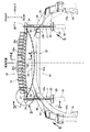
図1および図2に示すように、繊維強化樹脂製のキャビン11は、フロアパネル12、左右一対のサイドシル13,13、センタートンネル14、ダッシュパネル15等を一体に備える。キャビン11の前端から左右一対の金属製のフロントサイドフレーム16,16が前方に延びており、その前端に左右一対の繊維強化樹脂製のバンパービームエクステンション17,17が接続される。左右のバンパービームエクステンション17,17の前端部にバンパービーム18の車幅方向両端部が接続されるとともに、その後部外面に繊維強化樹脂製の左右一対のロアメンバ19,19の前後方向中間部が接続される。左右のバンパービームエクステンション17,17の間には、繊維強化樹脂製の四角枠状のフロントバルクヘッド20が設けられる。   As shown in FIGS. 1 and 2, the cabin 11 made of fiber reinforced resin is integrally provided with a floor panel 12, a pair of left and right side sills 13, 13, a center tunnel 14, a dash panel 15, and the like. A pair of left and right metal front side frames 16, 16 extend forward from the front end of the cabin 11, and a pair of left and right fiber reinforced resin bumper beam extensions 17, 17 are connected to the front end. Both ends of the bumper beam 18 in the vehicle width direction are connected to the front ends of the left and right bumper beam extensions 17 and 17, and intermediate portions in the front-rear direction of the pair of left and right lower members 19 and 19 made of fiber reinforced resin are connected to the rear outer surface. Is done. Between the left and right bumper beam extensions 17, 17, a square frame-shaped front bulkhead 20 made of fiber reinforced resin is provided.

図9に示すように、バンパービームエクステンション17は、車幅方向外側に位置する外側半体21と車幅方向内側に位置する内側半体22とからなり、相互に面対称なハット状断面の部材である外側半体21および内側半体22は、それぞれ側壁21a,22a、上壁21b,22b、下壁21c,22c、上部接合フランジ21d,22dおよび下部接合フランジ21e,22eを備えており、上部接合フランジ21d,22dおよび下部接合フランジ21e,22は接着により接合される。バンパービームエクステンション17は、その断面積が後方から前方に向かって減少するように先細にテーパーするが、肉厚は全体で均一に形成される。   As shown in FIG. 9, the bumper beam extension 17 is composed of an outer half body 21 positioned on the outer side in the vehicle width direction and an inner half body 22 positioned on the inner side in the vehicle width direction, and members having hat-shaped cross sections that are plane-symmetric with each other. The outer half 21 and the inner half 22 are provided with side walls 21a, 22a, upper walls 21b, 22b, lower walls 21c, 22c, upper joining flanges 21d, 22d and lower joining flanges 21e, 22e, respectively. The joining flanges 21d and 22d and the lower joining flanges 21e and 22 are joined by bonding. The bumper beam extension 17 is tapered so that its cross-sectional area decreases from the rear to the front, but the wall thickness is uniformly formed as a whole.

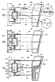
バンパービームエクステンション17の後端に結合される後部取付部材23は矩形板状の本体部23aの上縁および下縁から前方に延びる上部横リブ23bおよび下部横リブ23cと、上部横リブ23bおよび下部横リブ23c間を接続するように上下方向に延びる左右一対の縦リブ23d,23eと、左右一対の縦リブ23d,23eから左右方向に延びる6枚の中間横リブ23f…とを備える。上部横リブ23b、下部横リブ23cおよび左右一対の縦リブ23d,23eは筒状閉断面を構成し、その内周面にバンパービームエクステンション17の後端の外周面が密着するように嵌合して接着により固定される。   The rear mounting member 23 coupled to the rear end of the bumper beam extension 17 includes an upper lateral rib 23b and a lower lateral rib 23c extending forward from an upper edge and a lower edge of the rectangular plate-shaped main body 23a, and an upper lateral rib 23b and a lower part. A pair of left and right vertical ribs 23d and 23e extending in the vertical direction so as to connect the horizontal ribs 23c, and six intermediate horizontal ribs 23f extending in the left and right direction from the pair of left and right vertical ribs 23d and 23e are provided. The upper horizontal rib 23b, the lower horizontal rib 23c and the pair of left and right vertical ribs 23d and 23e form a cylindrical closed cross section, and are fitted so that the outer peripheral surface of the rear end of the bumper beam extension 17 is in close contact with the inner peripheral surface thereof. Fixed by bonding.

前部取付部材24は上述した後部取付部材23と類似した形状を有する部材であって、矩形板状の本体部24aの上縁および下縁から前方に延びる上部横リブ24bおよび下部横リブ24cと、上部横リブ24bおよび下部横リブ24c間を接続するように上下方向に延びる左右一対の縦リブ24d,24e、左右一対の縦リブ24d,24eから左右方向に延びる4枚の中間横リブ24f…とを備える。上部横リブ24b、下部横リブ24cおよび左右一対の縦リブ24d,24eは筒状閉断面を構成し、その内周面にバンパービームエクステンション17の前端の外周面が密着するように嵌合して接着により固定される。   The front mounting member 24 is a member having a shape similar to that of the rear mounting member 23 described above, and includes an upper lateral rib 24b and a lower lateral rib 24c that extend forward from the upper edge and the lower edge of the rectangular plate-shaped main body portion 24a. , A pair of left and right vertical ribs 24d, 24e extending in the vertical direction so as to connect the upper horizontal rib 24b and the lower horizontal rib 24c, four intermediate horizontal ribs 24f extending in the left-right direction from the pair of left and right vertical ribs 24d, 24e,. With. The upper horizontal rib 24b, the lower horizontal rib 24c, and the pair of left and right vertical ribs 24d and 24e constitute a cylindrical closed cross section, and are fitted so that the outer peripheral surface of the front end of the bumper beam extension 17 is in close contact with the inner peripheral surface thereof. It is fixed by bonding.

このとき、バンパービームエクステンション17の上部接合フランジ21d,22dおよび下部接合フランジ21e,22は段部a,bを有しており(図4および図9参照)、段部a,bよりも前側の部分だけが前記筒状閉断面内に嵌合することで、上部横リブ24bおよび下部横リブ24cの後縁が段部a,bの前縁に当接可能に対向する。また前部取付部材24はバンパービーム17の中心線Lに対して左右非対称であり、本体部24aの車幅方向内側部分が延長部24gの分だけ車幅方向外側部分よりも長くなっている(図8および図9参照)。   At this time, the upper joint flanges 21d and 22d and the lower joint flanges 21e and 22 of the bumper beam extension 17 have stepped portions a and b (see FIGS. 4 and 9), which are in front of the stepped portions a and b. Only the portion fits into the cylindrical closed cross section, so that the rear edges of the upper lateral rib 24b and the lower lateral rib 24c are opposed to the front edges of the step portions a and b. Further, the front mounting member 24 is asymmetrical with respect to the center line L of the bumper beam 17, and the inner portion in the vehicle width direction of the main body portion 24a is longer than the outer portion in the vehicle width direction by the extension portion 24g ( FIG. 8 and FIG. 9).

このようにして一体化されたバンパービームエクステンション17、後部取付部材23および前部取付部材24は、フロントサイドフレーム16の前端に溶接した矩形状の取付プレート25の前端に4本のボルト26…で締結される。   The bumper beam extension 17, the rear mounting member 23, and the front mounting member 24 integrated in this way are formed by four bolts 26 at the front end of a rectangular mounting plate 25 welded to the front end of the front side frame 16. It is concluded.

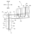
図2、図4および図8に示すように、バンパービーム18は、鋼板製のバンパービーム本体27と繊維強化樹脂製の衝撃吸収部材28とで構成される。バンパービーム本体27は、底壁27a、上壁27b、下壁27c、上部フランジ27dおよび下部フランジ27eを有して後方に開口するハット状断面の部材であり、平面視で車幅方向中央部が前方に突出するように弧状に湾曲する。バンパービーム本体27の車幅方向外端部は、各2本のボルト29,29で前部取付部材24の本体部24aを車幅方向内側に延長した延長部24gに締結される。この状態で、バンパービーム本体27の車幅方向外端はバンパービームエクステンション17の中心線Lよりも車幅方向外側に突出する(図8参照)。   As shown in FIGS. 2, 4 and 8, the bumper beam 18 includes a bumper beam main body 27 made of a steel plate and an impact absorbing member 28 made of fiber reinforced resin. The bumper beam body 27 is a hat-shaped cross-section member that has a bottom wall 27a, an upper wall 27b, a lower wall 27c, an upper flange 27d, and a lower flange 27e, and opens rearward. Curved in an arc so as to protrude forward. The outer end portion in the vehicle width direction of the bumper beam main body 27 is fastened to an extension portion 24g obtained by extending the main body portion 24a of the front mounting member 24 inward in the vehicle width direction with two bolts 29 and 29, respectively. In this state, the outer end in the vehicle width direction of the bumper beam body 27 protrudes outward in the vehicle width direction from the center line L of the bumper beam extension 17 (see FIG. 8).

バンパービーム本体27の前面を覆う衝撃吸収部材28は、上壁28aおよび下壁28bを有するV字状断面の部材であって、上壁28aおよび下壁28bがそれぞれバンパービーム本体27の上壁27bおよび下壁27cに接着により固定される。衝撃吸収部材28の上壁28aおよび下壁28bには前後方向に延びる多数のビード28c…が形成される。バンパービーム本体27に衝撃吸収部材28を結合した状態で、両者は中空閉断面を構成し、衝撃吸収部材28の車幅方向外端は、バンパービーム本体27を前部取付部材24に締結する2本のボルト29,29の近傍に位置している(図8参照)。   The shock absorbing member 28 covering the front surface of the bumper beam main body 27 is a member having a V-shaped cross section having an upper wall 28a and a lower wall 28b, and the upper wall 28a and the lower wall 28b are respectively the upper wall 27b of the bumper beam main body 27. And it fixes to the lower wall 27c by adhesion | attachment. A large number of beads 28c... Extending in the front-rear direction are formed on the upper wall 28a and the lower wall 28b of the shock absorbing member 28. In the state where the shock absorbing member 28 is coupled to the bumper beam main body 27, both form a hollow closed cross section, and the outer end in the vehicle width direction of the shock absorbing member 28 fastens the bumper beam main body 27 to the front mounting member 24. It is located in the vicinity of the bolts 29, 29 (see FIG. 8).

図1、図2および図7(B)に示すように、左右のバンパービームエクステンション17,17の内側半体22,22の側壁22a,22aの車幅方向内面に、繊維強化樹脂製のフロントバルクヘッド支持部材30,30を介して繊維強化樹脂製のフロントバルクヘッド20が支持される。フロントバルクヘッド20は、ロアビーム32aおよび左右一対のサイドビーム32b,32bを有して正面視でU字状に湾曲する下部部材32の左右上端部に、左右一対のアッパーメンバ33a,33aと一体に形成されて平面視でU字状に湾曲する上部部材33のアッパービーム33bを結合することで四角枠状に構成され、下部部材32の左右一対のサイドビーム32b,32bがフロントバルクヘッド支持部材30,30に結合される。   As shown in FIGS. 1, 2, and 7 (B), a front bulk made of fiber reinforced resin is formed on the inner surfaces in the vehicle width direction of the side walls 22 a and 22 a of the inner halves 22 and 22 of the left and right bumper beam extensions 17 and 17. The front bulkhead 20 made of fiber reinforced resin is supported via the head support members 30 and 30. The front bulkhead 20 has a lower beam 32a and a pair of left and right side beams 32b and 32b, and is integrally formed with a pair of left and right upper members 33a and 33a at left and right upper ends of a lower member 32 that curves in a U shape in a front view. The upper beam 33b of the upper member 33 that is formed and curved in a U shape in plan view is coupled to form a rectangular frame shape, and the pair of left and right side beams 32b and 32b of the lower member 32 are formed on the front bulkhead support member 30. , 30.

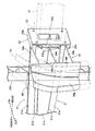
図1〜図3、図5、図6および図7(C)に示すように、左右のバンパービームエクステンション17,17の外側半体21,21の側壁21a,21aの車幅方向外面に、繊維強化樹脂製のロアメンバ支持部材34,34を介して繊維強化樹脂製のロアメンバ19,19の前後方向中間部が支持される。ロアメンバ支持部材34の内側部は、底壁34a、上壁34bおよび下壁34cを備えて後方に開放するコ字状断面に形成され、その内部に補強用の横リブ34dを備えるとともに、その車幅方向内端を覆う内側壁34eが外側半体21,21の側壁21a,21aに接着される。またロアメンバ支持部材34の内側部の車幅方向外側に連なる外側部は、外側壁34fおよび前壁34gを備えてL字状断面に形成され、そこにロアメンバ19の前壁19aおよび側壁19bが接着される(図7(C)参照)。   As shown in FIGS. 1 to 3, 5, 6, and 7C, fibers are formed on the outer surfaces in the vehicle width direction of the side walls 21a and 21a of the outer halves 21 and 21 of the left and right bumper beam extensions 17 and 17. The intermediate portions in the front-rear direction of the lower members 19, 19 made of fiber reinforced resin are supported via the lower member support members 34, 34 made of reinforced resin. An inner portion of the lower member support member 34 is formed in a U-shaped cross section that includes a bottom wall 34a, an upper wall 34b, and a lower wall 34c, and is open rearward. An inner side wall 34e covering the inner end in the width direction is bonded to the side walls 21a and 21a of the outer half bodies 21 and 21. The outer part of the inner part of the lower member support member 34 that extends to the outer side in the vehicle width direction is formed with an L-shaped cross section including an outer wall 34f and a front wall 34g, and the front wall 19a and the side wall 19b of the lower member 19 are bonded thereto. (See FIG. 7C).

ロアメンバ支持部材34の後向きに延びる上壁34bおよび下壁34cの後端は、後部取付部材23の前向きに延びる上部横リブ23bおよび下部横リブ23cの前端に対向しており、その際に、ロアメンバ支持部材34の後向きに延びる上壁34bは後部取付部材23の上部横リブ23bの僅かに上方に位置するとともに、ロアメンバ支持部材34の後向きに延びる下壁34cは後部取付部材23の下部横リブ23cの僅かに下方に位置している。前方側に位置するフロントバルクヘッド支持部材30,30の肉厚t1は、後方側に位置するロアメンバ支持部材34,34の肉厚t2よりも薄くなっている(図7(A)参照)。   The rear ends of the upper wall 34b and the lower wall 34c that extend rearward of the lower member support member 34 are opposed to the front ends of the upper lateral rib 23b and lower lateral rib 23c that extend forward of the rear mounting member 23. The upper wall 34 b extending rearward of the support member 34 is positioned slightly above the upper lateral rib 23 b of the rear mounting member 23, and the lower wall 34 c extending rearward of the lower member support member 34 is the lower lateral rib 23 c of the rear mounting member 23. It is located slightly below. The thickness t1 of the front bulkhead support members 30 and 30 positioned on the front side is thinner than the thickness t2 of the lower member support members 34 and 34 positioned on the rear side (see FIG. 7A).

図1および図5に示すように、前下方に湾曲するロアメンバ19,19の前端と、フロントバルクヘッド20の下部部材32の左右の角部とが繊維強化樹脂製の連結部材35,35で接続される。   As shown in FIGS. 1 and 5, the front ends of the lower members 19, 19 that curve forward and downward and the left and right corners of the lower member 32 of the front bulkhead 20 are connected by connecting members 35, 35 made of fiber reinforced resin. Is done.

次に、上記構成を備えた本発明の実施の形態の作用を説明する。   Next, the operation of the embodiment of the present invention having the above configuration will be described.

車両が前面衝突して衝突荷重がバンパービーム18に入力すると、先ずバンパービーム18の前面側の繊維強化樹脂製の衝撃吸収部材28が圧壊して衝突エネルギーを吸収する。   When the vehicle collides with the front and a collision load is input to the bumper beam 18, first, the impact absorbing member 28 made of fiber reinforced resin on the front side of the bumper beam 18 is crushed and absorbs the collision energy.

続いて、前記衝突荷重はバンパービーム18の後面側のバンパービーム本体27に伝達されるが、底壁27a、上壁27bおよび下壁27cを有してコ字状断面に形成された鋼板製のバンパービーム本体27は延性が高いため、後方に弧状に撓むだけで折れ曲がることはなく、その車幅方向両端部から左右のバンパービームエクステンション17,17に衝突荷重を効果的に伝達することで、バンパービームエクステンション17,17を前後方向に圧壊してエネルギー吸収を行うことができる。このとき、バンパービームエクステンション17の肉厚は前方から後方に向かって均一であり、かつバンパービームエクステンション17の閉断面の断面積は前方から後方に向かって拡大するので(図7参照)、前面衝突の荷重によってバンパービームエクステンション17を強度の低い前端側から強度の高い後端側へと順次圧壊して衝撃吸収性能を高めることができる。   Subsequently, the collision load is transmitted to the bumper beam main body 27 on the rear surface side of the bumper beam 18, and is made of a steel plate having a bottom wall 27a, an upper wall 27b, and a lower wall 27c and having a U-shaped cross section. Since the bumper beam body 27 has high ductility, the bumper beam body 27 does not bend only by bending backward in an arc shape, and effectively transmits a collision load from both ends in the vehicle width direction to the left and right bumper beam extensions 17, 17. The bumper beam extensions 17 and 17 can be crushed in the front-rear direction to absorb energy. At this time, the thickness of the bumper beam extension 17 is uniform from the front to the rear, and the sectional area of the closed cross section of the bumper beam extension 17 increases from the front to the rear (see FIG. 7). The bumper beam extension 17 can be sequentially crushed from the low-strength front end side to the high-strength rear end side by the load, thereby improving the shock absorbing performance.

しかもバンパービーム本体27は底壁27a、上壁27bおよび下壁27cを有して後方に向けて開口するコ字状断面の部材であり、衝撃吸収部材28は上壁28aおよび下壁28bを有して後方に向けて開口するV字状断面の部材であり、バンパービーム本体27の上壁27bおよび下壁27cに衝撃吸収部材28の上壁28aおよび下壁28bを結合したので(図4参照)、バンパービーム18を中空閉断面に構成してエネルギー吸収効果を高めるとともに、バンパービーム18の曲げ剛性を増加させてバンパービームエクステンション17,17への衝突荷重の伝達効率を更に高めることができる。   In addition, the bumper beam main body 27 is a member having a U-shaped cross section having a bottom wall 27a, an upper wall 27b, and a lower wall 27c and opening rearward. The shock absorbing member 28 has an upper wall 28a and a lower wall 28b. Since the upper wall 28b and the lower wall 28b of the shock absorbing member 28 are coupled to the upper wall 27b and the lower wall 27c of the bumper beam main body 27 (see FIG. 4). ), The bumper beam 18 can be formed in a hollow closed cross section to enhance the energy absorption effect, and the bending rigidity of the bumper beam 18 can be increased to further increase the efficiency of transmitting the collision load to the bumper beam extensions 17 and 17.

このとき、衝撃吸収部材28の上壁28aおよび下壁28bに前後方向に延びるビード28c…が形成されているため、衝撃吸収部材28の圧壊によるエネルギー吸収量を増加させることができる。   At this time, since the beads 28c... Extending in the front-rear direction are formed on the upper wall 28a and the lower wall 28b of the impact absorbing member 28, the amount of energy absorbed by the collapse of the impact absorbing member 28 can be increased.

仮に、バンパービーム18が繊維強化樹脂製の衝撃吸収部材28だけで構成されているとすると、衝突荷重で衝撃吸収部材28が容易に折れ曲がってしまい、衝突荷重を左右のバンパービームエクステンション17,17に効率的に伝達することができず、バンパービームエクステンション17,17の圧壊によるエネルギー吸収が充分に行われない可能性がある。また仮に、バンパービーム18の鋼板製のバンパービーム本体27だけで構成されているとすると、衝突荷重をバンパービームエクステンション17,17に伝達することは可能であるが、バンパービーム18自体は衝突エネルギーの吸収効果を発揮しないので、全体として衝突エネルギーの吸収性能が低下してしまう可能性がある。   If the bumper beam 18 is composed only of the fiber reinforced resin impact absorbing member 28, the impact absorbing member 28 is easily bent by the collision load, and the collision load is applied to the left and right bumper beam extensions 17, 17. There is a possibility that the energy cannot be efficiently transmitted and the energy absorption due to the collapse of the bumper beam extensions 17 and 17 is not sufficiently performed. If the bumper beam 18 is composed only of a bumper beam body 27 made of a steel plate, it is possible to transmit a collision load to the bumper beam extensions 17 and 17, but the bumper beam 18 itself has a collision energy. Since the absorption effect is not exhibited, there is a possibility that the collision energy absorption performance as a whole is lowered.

それに対し、本実施の形態によれば、バンパービーム本体27および衝撃吸収部材28を結合してバンパービーム18を構成したことにより、バンパービーム18自体で衝突エネルギーの吸収効果を発揮させながら,バンパービームエクステンション17,17に確実に圧壊して衝突エネルギーの吸収効果を高めることができる。   On the other hand, according to the present embodiment, the bumper beam body 27 and the impact absorbing member 28 are combined to form the bumper beam 18, so that the bumper beam 18 itself exerts an impact energy absorbing effect while the bumper beam 18 is exerted. The extensions 17 and 17 can be reliably crushed to enhance the impact energy absorption effect.

またバンパービームエクステンション17の前端部に車幅方向内側に延びる延長部24gを有する前部取付部材24を固定し、バンパービーム本体27の車幅方向外端をバンパービームエクステンション17の中心線Lよりも車幅方向外側に位置させた状態で、バンパービーム本体27を延長部24gの前面にボルト29,29で締結したので(図8参照)、バンパービーム18およびバンパービームエクステンション17の結合部が成す角度が変化しないように前部取付部材24で強固に補強することで、バンパービームエクステンション17に曲げモーメントを作用させることなく前後方向の圧縮荷重を作用させ、バンパービームエクステンション17を前後方向に確実に圧壊することができる。   A front mounting member 24 having an extension 24g extending inward in the vehicle width direction is fixed to the front end portion of the bumper beam extension 17, and the outer end in the vehicle width direction of the bumper beam main body 27 is positioned more than the center line L of the bumper beam extension 17. Since the bumper beam main body 27 is fastened to the front surface of the extension 24g with bolts 29 and 29 (see FIG. 8) while being positioned outside in the vehicle width direction, the angle formed by the joint of the bumper beam 18 and the bumper beam extension 17 By firmly reinforcing the front mounting member 24 so as not to change, a compressive load in the front-rear direction is applied to the bumper beam extension 17 without applying a bending moment, and the bumper beam extension 17 is reliably crushed in the front-rear direction. can do.

また衝撃吸収部材28の車幅方向外端を、バンパービーム本体27および延長部24gのボルト29,29による締結部の近傍に位置させたので(図8参照)、衝撃吸収部材28の圧壊によるエネルギー吸収からバンパービームエクステンション17,17の圧壊によるエネルギー吸収にスムーズに切り換わってエネルギー吸収効果が高められる。   Further, since the outer end in the vehicle width direction of the impact absorbing member 28 is positioned in the vicinity of the fastening portion of the bumper beam main body 27 and the extension 24g by the bolts 29 and 29 (see FIG. 8), the energy by the collapse of the impact absorbing member 28 is obtained. The energy absorption effect is enhanced by smoothly switching from absorption to energy absorption by crushing the bumper beam extensions 17 and 17.

またバンパービームエクステンション17は中空閉断面の部材であり、前部取付部材24の後面から後方に突設した上部横リブ24b、下部横リブ24cおよび縦リブ24d,24e内側にバンパービームエクステンション17の前端部を嵌合して固定したので(図9参照)、バンパービームエクステンション17と前部取付部材24とを結合する際の位置決めを容易に行うことができるだけでなく、バンパービームエクステンション17に対して前部取付部材24が傾かないように強固に結合することで、バンパービーム18からバンパービームエクステンション17への衝突荷重の伝達を一層確実に行わせることができる。   Further, the bumper beam extension 17 is a member having a hollow closed cross section, and the front end of the bumper beam extension 17 is provided inside the upper lateral rib 24b, the lower lateral rib 24c, and the longitudinal ribs 24d and 24e protruding rearward from the rear surface of the front mounting member 24. Since the portions are fitted and fixed (see FIG. 9), the bumper beam extension 17 and the front mounting member 24 can be easily positioned, and the front of the bumper beam extension 17 can be easily fixed. By firmly coupling so that the part mounting member 24 does not tilt, it is possible to more reliably transmit the collision load from the bumper beam 18 to the bumper beam extension 17.

また繊維強化樹脂製の前部取付部材24の上部横リブ24bおよび下部横リブ24cはバンパービームエクステンション17の上部接合フランジ21d,22dおよび下部接合フランジ21e,22eの前端の段部a,bに当接可能に対峙するので(図4参照)、前面衝突の衝突荷重がバンパービーム18から前部取付部材24に入力したとき、後退する前部取付部材24の上部横リブ24bおよび下部横リブ24cがバンパービームエクステンションの上部接合フランジ21d,22dおよび下部接合フランジ21e,22eの前端の段部a,bに食い込んでエネルギー吸収効果を発揮することができる。   Further, the upper lateral rib 24b and the lower lateral rib 24c of the front mounting member 24 made of fiber reinforced resin are in contact with the step portions a and b at the front ends of the upper joint flanges 21d and 22d and the lower joint flanges 21e and 22e of the bumper beam extension 17. Since they face each other so as to come into contact (see FIG. 4), when the collision load of the frontal collision is input from the bumper beam 18 to the front mounting member 24, the upper horizontal rib 24b and the lower horizontal rib 24c of the front mounting member 24 retreating. The energy absorbing effect can be exerted by biting into the step portions a and b at the front ends of the upper joint flanges 21d and 22d and the lower joint flanges 21e and 22e of the bumper beam extension.

またバンパービームエクステンション17は左右一対のハット状断面を有する外側半体21および内側半体22の上部接合フランジ21d,22dおよび下部接合フランジ21e,22eどうしを結合して中空閉断面に構成され、取付プレート25に締結される後部支持部材23は前向きに突出する上部横リブ23b、下部横リブ23cおよび縦リブ23d,23eを備え、バンパービームエクステンション17の後端部を後部支持部材23の上部横リブ23b、下部横リブ23cおよび縦リブ23d,23eの内周に嵌合して固定したので(図9参照)、バンパービームエクステンション17の後端部を後部取付部材23に軽量で簡単な構造で強固に一体化することができ、前面衝突の衝突荷重でバンパービームエクステンション17がフロントサイドフレーム16の前端部の取付プレート25に対して押し付けられたとき、バンパービームエクステンション17が前後方向から傾むくのを防止することで、バンパービームエクステンション17全体を確実に圧壊してエネルギー吸収量を増加させることができる。   The bumper beam extension 17 has a hollow closed cross section formed by connecting upper joint flanges 21d and 22d and lower joint flanges 21e and 22e of the outer half body 21 and the inner half body 22 having a pair of left and right hat-shaped cross sections. The rear support member 23 fastened to the plate 25 includes an upper horizontal rib 23b, a lower horizontal rib 23c, and vertical ribs 23d and 23e protruding forward, and the rear end portion of the bumper beam extension 17 is used as the upper horizontal rib of the rear support member 23. 23b, lower horizontal rib 23c and vertical ribs 23d and 23e are fitted and fixed to the inner periphery (see FIG. 9), so that the rear end of the bumper beam extension 17 is firmly attached to the rear mounting member 23 with a light and simple structure. The bumper beam extension 17 is supported by the impact load of the frontal collision. When the bumper beam extension 17 is prevented from tilting from the front-rear direction when pressed against the mounting plate 25 at the front end portion of the front side frame 16, the entire bumper beam extension 17 is surely crushed and the amount of energy absorbed Can be increased.

またバンパービームエクステンション17の車幅方向外面に繊維強化樹脂製のロアメンバ支持部材34を固定し、ロアメンバ支持部材34は、底壁34a、上壁34bおよび下壁34cを有して後方に向けて開口するコ字状断面の内側部と、前壁34gおよび外側壁34fを有してロアメンバ19に固定されるL字状断面の外側部とを備えるので(図3および図5〜図7参照)、バンパービームエクステンション17から伝達される前面衝突の衝突荷重でロアメンバ支持部材34およびロアメンバ19を圧壊してエネルギー吸収効果を発揮することができる。   Further, a lower member support member 34 made of fiber reinforced resin is fixed to the outer surface of the bumper beam extension 17 in the vehicle width direction. The lower member support member 34 has a bottom wall 34a, an upper wall 34b, and a lower wall 34c and is opened rearward. And an outer portion of an L-shaped cross section having a front wall 34g and an outer wall 34f and fixed to the lower member 19 (see FIGS. 3 and 5 to 7). The lower member support member 34 and the lower member 19 can be crushed by the collision load of the frontal collision transmitted from the bumper beam extension 17 to exhibit an energy absorption effect.

またバンパービームエクステンション17の後部支持部材23は、本体部23a、上部横リブ23bおよび下部横リブ23cを有して前方に向けて開口するコ字状断面に形成され、後方に向けて開放するロアメンバ支持部材34の開口部は後部支持部材23の開口部の内部に嵌合するので(図3参照)、ロアメンバ支持部材34に前面衝突の衝突荷重が入力したときに、ロアメンバ支持部材34の開口部が後部取付部材23の開口部の内部に嵌合することでエネルギー吸収効果を発揮することができる。   The rear support member 23 of the bumper beam extension 17 has a main body portion 23a, an upper lateral rib 23b, and a lower lateral rib 23c. The lower support member 23 is formed in a U-shaped cross section that opens toward the front and opens toward the rear. Since the opening of the support member 34 fits inside the opening of the rear support member 23 (see FIG. 3), when the collision load of the frontal collision is input to the lower member support member 34, the opening of the lower member support member 34 However, it is possible to exert an energy absorption effect by fitting inside the opening of the rear mounting member 23.

またバンパービームエクステンション17は、前側に位置する薄肉のフロントバルクヘッド支持部材30および後側に位置する厚肉のロアメンバ支持部材34を備えているので、バンパービームエクステンション17の強度は前側から後側に向かって次第に高くなり、これにより前面衝突の衝突荷重でバンパービームエクステンション17を前端側から順次圧壊させてエネルギーの吸収効果を高めることができる。   The bumper beam extension 17 includes a thin front bulkhead support member 30 located on the front side and a thick lower member support member 34 located on the rear side, so that the strength of the bumper beam extension 17 changes from the front side to the rear side. As a result, the bumper beam extension 17 is sequentially crushed from the front end side by the collision load of the frontal collision, thereby enhancing the energy absorption effect.

またフロントバルクヘッド20は、平面視で後方に向けて開放する略U字状の上部部材33の車幅方向中央のアッパービーム33bと、正面視で上方に向けて開放する略U字状の下部部材32とを結合して正面視で矩形枠状に構成され、下部部材32の車幅方向両側の角部とロアメンバ19,19の前端部とを、繊維強化樹脂製の連結部材35,35を介して連結したので(図1参照)、バンパービームエクステンション17,17からフロントバルクヘッド20に伝達された衝突荷重を連結部材35,35を介してロアメンバ19,19に分散して効果的に吸収することができる。   The front bulkhead 20 includes an upper beam 33b at the center in the vehicle width direction of the substantially U-shaped upper member 33 that opens rearward in a plan view, and a substantially U-shaped lower portion that opens upward in a front view. The member 32 is coupled to form a rectangular frame shape when viewed from the front, and the corners on both sides in the vehicle width direction of the lower member 32 and the front end portions of the lower members 19 and 19 are connected to the connecting members 35 and 35 made of fiber reinforced resin. 1 and the collision load transmitted from the bumper beam extensions 17 and 17 to the front bulkhead 20 is distributed to the lower members 19 and 19 through the connecting members 35 and 35 and effectively absorbed. be able to.

以上、本発明の実施の形態を説明したが、本発明はその要旨を逸脱しない範囲で種々の設計変更を行うことが可能である。   The embodiments of the present invention have been described above, but various design changes can be made without departing from the scope of the present invention.

17 バンパービームエクステンション
18 バンパービーム
24 前部取付部材
24b 上部横リブ(リブ)
24c 下部横リブ(リブ)
24d 縦リブ(リブ)
24e 縦リブ(リブ)
24g 延長部
27 バンパービーム本体
27a 底壁
27b 上壁
27c 下壁
28 衝撃吸収部材
28a 上壁
28b 下壁
28c ビード
L バンパービームエクステンションの中心線
17 Bumper beam extension 18 Bumper beam 24 Front mounting member 24b Upper lateral rib (rib)
24c Lower lateral rib (rib)
24d Vertical rib (rib)
24e Vertical rib (rib)
24g Extension 27 Bumper beam main body 27a Bottom wall 27b Upper wall 27c Lower wall 28 Shock absorbing member 28a Upper wall 28b Lower wall 28c Bead L Center line of bumper beam extension

Claims (6)

鋼板製のバンパービーム本体(27)の前面に繊維強化樹脂製の衝撃吸収部材(28)を結合したバンパービーム(18)の車幅方向両端部を、前後方向に延びる左右一対の繊維強化樹脂製のバンパービームエクステンション(17)の前端部に固定したことを特徴とする自動車の車体前部構造。   A pair of left and right fiber reinforced resins extending in the front-rear direction at both ends in the vehicle width direction of the bumper beam (18) in which a shock absorbing member (28) made of fiber reinforced resin is coupled to the front surface of a bumper beam body (27) made of steel plate A vehicle body front structure, which is fixed to the front end of a bumper beam extension (17). 前記バンパービームエクステンション(17)の前端部に車幅方向内側に延びる延長部(24g)を有する前部取付部材(24)を固定し、前記バンパービーム本体(27)の車幅方向外端を前記バンパービームエクステンション(17)の中心線(L)よりも車幅方向外側に位置させた状態で、前記バンパービーム本体(27)を前記延長部(24g)の前面に締結したことを特徴とする、請求項1に記載の自動車の車体前部構造。   A front mounting member (24) having an extension (24g) extending inward in the vehicle width direction is fixed to the front end of the bumper beam extension (17), and the outer end in the vehicle width direction of the bumper beam body (27) is The bumper beam main body (27) is fastened to the front surface of the extension portion (24g) in a state of being positioned on the outer side in the vehicle width direction from the center line (L) of the bumper beam extension (17). The vehicle body front part structure according to claim 1. 前記バンパービーム本体(27)は底壁(27a)、上壁(27b)および下壁(27c)を有して後方に向けて開口する略コ字状断面の部材であり、前記衝撃吸収部材(28)は上壁(28a)および下壁(28b)を有して後方に向けて開口する略V字状断面の部材であり、前記バンパービーム本体(27)の上壁(27b)および下壁(27c)に前記衝撃吸収部材(28)の上壁(28a)および下壁(28b)を結合したことを特徴とする、請求項1または請求項2に記載の自動車の車体前部構造。   The bumper beam body (27) is a member having a bottom wall (27a), an upper wall (27b), and a lower wall (27c) and having a substantially U-shaped cross section that opens rearward, and the shock absorbing member ( 28) is a member having a substantially V-shaped cross section having an upper wall (28a) and a lower wall (28b) and opening rearward, and the upper wall (27b) and the lower wall of the bumper beam body (27). The vehicle body front part structure according to claim 1 or 2, wherein an upper wall (28a) and a lower wall (28b) of the shock absorbing member (28) are coupled to (27c). 前記衝撃吸収部材(28)の上壁(28a)および下壁(28b)は前後方向に延びる複数のビード(28c)を備えることを特徴とする、請求項3に記載の自動車の車体前部構造。   The vehicle body front structure according to claim 3, wherein the upper wall (28a) and the lower wall (28b) of the shock absorbing member (28) include a plurality of beads (28c) extending in the front-rear direction. . 前記衝撃吸収部材(28)の車幅方向外端を、前記バンパービーム本体(27)および前記延長部(24g)の締結部の近傍に位置させたことを特徴とする、請求項1〜請求項4の何れか1項に記載の自動車の車体前部構造。   The outer end in the vehicle width direction of the shock absorbing member (28) is positioned in the vicinity of a fastening portion of the bumper beam main body (27) and the extension portion (24g). 5. The vehicle body front structure according to any one of 4 above. 前記バンパービームエクステンション(17)は中空閉断面の部材であり、前記前部取付部材(24)の後面から後方に突設した閉断面のリブ(24b,24c,24d,24e)の内側に前記バンパービームエクステンション(17)の前端部を嵌合して固定したことを特徴とする、請求項2に記載の自動車の車体前部構造。   The bumper beam extension (17) is a member having a hollow closed cross section, and the bumper beam extension (17) is disposed inside a rib (24b, 24c, 24d, 24e) having a closed cross section projecting rearward from the rear surface of the front mounting member (24). The vehicle body front structure according to claim 2, wherein the front end of the beam extension (17) is fitted and fixed.
JP2012201994A 2012-09-13 2012-09-13 Vehicle body front part structure of automobile Pending JP2016010982A (en)

Priority Applications (3)

Application Number Priority Date Filing Date Title
JP2012201994A JP2016010982A (en) 2012-09-13 2012-09-13 Vehicle body front part structure of automobile
PCT/JP2013/074683 WO2014042211A1 (en) 2012-09-13 2013-09-12 Structure for front part of body of automobile
EP13837779.1A EP2896535B1 (en) 2012-09-13 2013-09-12 Structure for front part of body of automobile

Applications Claiming Priority (1)

Application Number Priority Date Filing Date Title
JP2012201994A JP2016010982A (en) 2012-09-13 2012-09-13 Vehicle body front part structure of automobile

Publications (1)

Publication Number Publication Date
JP2016010982A true JP2016010982A (en) 2016-01-21

Family

ID=55227994

Family Applications (1)

Application Number Title Priority Date Filing Date
JP2012201994A Pending JP2016010982A (en) 2012-09-13 2012-09-13 Vehicle body front part structure of automobile

Country Status (1)

Country Link
JP (1) JP2016010982A (en)

Cited By (6)

* Cited by examiner, † Cited by third party
Publication number Priority date Publication date Assignee Title
WO2019117110A1 (en) * 2017-12-14 2019-06-20 マツダ株式会社 Shock absorbing structure for vehicles
WO2020085385A1 (en) 2018-10-24 2020-04-30 日本製鉄株式会社 Automobile structural member
DE102019133865A1 (en) 2018-12-20 2020-06-25 Suzuki Motor Corporation Vehicle front section construction
JP2021088326A (en) * 2019-12-06 2021-06-10 本田技研工業株式会社 Vehicle body front part structure
JP7294115B2 (en) 2019-12-20 2023-06-20 いすゞ自動車株式会社 bumper
US11827280B2 (en) 2021-11-09 2023-11-28 Hyundai Motor Company Vehicle load distribution system

Cited By (10)

* Cited by examiner, † Cited by third party
Publication number Priority date Publication date Assignee Title
WO2019117110A1 (en) * 2017-12-14 2019-06-20 マツダ株式会社 Shock absorbing structure for vehicles
CN111479725A (en) * 2017-12-14 2020-07-31 马自达汽车株式会社 Impact absorbing structure for vehicle
EP3722160A4 (en) * 2017-12-14 2020-10-28 Mazda Motor Corporation Shock absorbing structure for vehicles
WO2020085385A1 (en) 2018-10-24 2020-04-30 日本製鉄株式会社 Automobile structural member
US11465687B2 (en) 2018-10-24 2022-10-11 Nippon Steel Corporation Automobile structural member
DE102019133865A1 (en) 2018-12-20 2020-06-25 Suzuki Motor Corporation Vehicle front section construction
JP2021088326A (en) * 2019-12-06 2021-06-10 本田技研工業株式会社 Vehicle body front part structure
JP7038095B2 (en) 2019-12-06 2022-03-17 本田技研工業株式会社 Body front structure
JP7294115B2 (en) 2019-12-20 2023-06-20 いすゞ自動車株式会社 bumper
US11827280B2 (en) 2021-11-09 2023-11-28 Hyundai Motor Company Vehicle load distribution system

Similar Documents

Publication Publication Date Title
WO2014042211A1 (en) Structure for front part of body of automobile
JP4254843B2 (en) Vehicle front structure
JP5029135B2 (en) Car side body structure
JP5593813B2 (en) Body reinforcement structure
WO2013121890A1 (en) Vehicle body bottom structure
JP6204437B2 (en) Auto body structure
JP5927695B2 (en) Lower body structure
JP2016010983A (en) Vehicle body front part structure of automobile
JP5825680B2 (en) Vehicle cabin structure
JP2016010982A (en) Vehicle body front part structure of automobile
JPWO2012121142A1 (en) Car body rear structure
JP5846952B2 (en) Lower body structure
JP2008230460A (en) Lower body structure of vehicle
JP6032629B2 (en) Automobile center pillar structure
JP2013103650A (en) Vehicle body floor structure
JP6103085B2 (en) Vehicle front structure
WO2020059248A1 (en) Vehicle lower body structure
JP6062883B2 (en) Body front structure
JP6057294B2 (en) Auto body structure
JP6471768B2 (en) Front body structure of the vehicle
JP5974418B2 (en) Auto body structure
JP5864354B2 (en) Body front structure
JP5928880B2 (en) CFRP cabin of automobile
JP2016112914A (en) Front vehicle body structure
JP2016013788A (en) Vehicle bumper beam structure